Bw500全套说明书
古野BNWAS中文操作说明书BR500

操作手册船桥导航监视警报系统 (BNWAS)BR-500型号Pub. No. OZS-44610-D DATE OF ISSUE: MAY. 2012i重要注意事项概述• 设备操作员必须阅读和遵守本手册的说明。
错误的操作或维护可能导致保修失效,或造成伤害。
• 未经 FURUNO 的书面许可,不得复制本手册的任何部分。
• 如果本手册丢失或破损,请咨询经销商如何更换。
• 本手册内容和设备规格如有更改,恕不另行通知。
• 本手册中屏幕显示(或图示)范例可能与您的屏幕显示有所区别。
您所看到的屏幕取决于您的系统配置和设备设置。
• 请保留手册,以备将来参考。
• 如未经 FURUNO 授权擅自对设备(包括软件)进行任何改装/修改,保修将失效。
• 所有品牌和产品名称均为各自持有者的商标、注册商标或服务标记。
如何丢弃本产品须根据当地工业废品处理规范丢弃本产品。
如在美国处理,请参阅电子工业联盟的主页 (/),了解正确的处理方法。
如何丢弃废旧电池有些 FURUNO 产品使用电池。
如要了解您的产品是否使用电池,请参阅维护章节。
如果使用电池,请遵守以下说明。
请用胶带封住电池正负接头后再弃置,防止因短路造成燃烧或发热。
在欧盟打叉的垃圾桶标志表示禁止将所有类型的电池丢弃到标准垃圾桶或垃圾站。
请根据所在国家的法规和《电池指令 2006/66/EU 》,将废旧电池带到电池回收站点。
在美国莫比斯环符号(三箭追逐环)表示必须回收的镍镉和铅酸充电电池。
请根据当地法律将废旧电池带到电池回收站点。
在其他国家不存在电池回收标志国际标准。
其他国家如在将来制作自己的回收标志,该标志的数量将增加。
PbNi-Cd安全说明parts inside. ii安全说明iii目录前言 (vi)系统配置 (viii)1.主警报面板...............................................................................................................1-1 1.1控制钮..............................................................................................................................................1-1 1.2如何开启/关闭系统.........................................................................................................................1-1 1.3BNWAS 显示屏................................................................................................................................1-2 1.4如何调整 LCD/LED 亮度、按键背光................................................................................................1-3 1.5如何选择支援船员............................................................................................................................1-4 1.6模式..................................................................................................................................................1-4 1.7休眠期..............................................................................................................................................1-4 1.8监视警报顺序...................................................................................................................................1-5 1.9帮助区域...........................................................................................................................................1-81.9.1 系统故障指示........................................................................................................................1-81.9.2 操作性事件指示.....................................................................................................................1-9 1.10如何进行紧急呼叫............................................................................................................................1-91.11如何呼叫导航员..............................................................................................................................1-102.另选购设备...............................................................................................................2-1 2.1计时器重置面板 BR-530,BR-550..................................................................................................2-1 2.2船舱面板 BR-540.............................................................................................................................2-2 2.3运动检测器 BR-560..........................................................................................................................2-32.4闪光灯 BR-570.................................................................................................................................2-43.维护与故障排除........................................................................................................3-1 3.1维护..................................................................................................................................................3-1 3.2更换保险丝.......................................................................................................................................3-1 3.3故障排除...........................................................................................................................................3-2 3.4如何检查处理器单元/船舱面板/计时器重置面板之间的连接........................................................3-33.5主要部件的预期寿命.........................................................................................................................3-44.安装..........................................................................................................................4-1 4.1设备列表...........................................................................................................................................4-1 4.2安装注意事项...................................................................................................................................4-2 4.3主警报面板 BR-510.........................................................................................................................4-34.3.1 桌面安装................................................................................................................................4-34.3.2 嵌入式安装............................................................................................................................4-34.3.3 屏蔽膜(选件).....................................................................................................................4-4 4.4处理器单元 BR-520.........................................................................................................................4-4 4.5计时器重置面板 BR-530、机舱面板 BR-540、运动检测器 BR-560、闪光灯 BR-570(另选购单元).........................................................................................................................................................4-44.5.1 嵌入式安装............................................................................................................................4-44.5.2 舱壁安装................................................................................................................................4-5 4.6防水计时器重置面板 BR-550(选件)............................................................................................4-9 4.7布线................................................................................................................................................4-114.7.1 处理器单元..........................................................................................................................4-114.7.2 布线信息..............................................................................................................................4-134.7.3 主警报面板..........................................................................................................................4-144.7.4 计时器重置面板、机舱面板、运动检测器、闪光灯.............................................................4-144.7.5 闪光灯.................................................................................................................................4-15 ivSUMARIO4.7.6 如何装配船舱面板、计时器重置面板、闪光灯和运动检测器的电缆...................................4-15 4.8DIP 开关,旋转开关设置...............................................................................................................4-16 4.9如何调整 LED 亮度.......................................................................................................................4-17 4.10菜单设置........................................................................................................................................4-174.10.1 管理员菜单........................................................................................................................4-174.10.2 检修菜单...........................................................................................................................4-21 4.11I/O 语句信息..................................................................................................................................4-22附录1 菜单树、缩略语、JIS 电缆选用指南..............................................................AP-1规格............................................................................................................................SP-1装箱单..........................................................................................................................A-1外形图..........................................................................................................................D-1接线图..........................................................................................................................S-1索引.............................................................................................................................IN-1vvi前言尊敬的 BR-500 用户承蒙惠购 FURUNO BR-500 船桥导航监视警报系统 (BNWAS )。
Bw500全套说明书

不对称重传 感器配平, 将影响皮带 称量系统
双传感器皮 带称
称重传感器 A
进入P295
标定砝码
按
称重传感器 B
如果在P003 里称重传感 器的数量设 置 为4只,本 项选2
按
如果有四只 称重传感 器,则继续 按
按
按
配平后需要对称重传感器进行零点 和
按
按
称重传感器 的配平现在 完成,下面 进行零点和 量程的标定 。
按速度传感 器上的铭牌 输入传感器 数据,仪表 自动计算并 输入P015
例:恒速, 每米100.3 个脉冲
出厂设定的 皮带长度
例:皮带长 度为25m 出厂设定的
如果选择 Ecal-模拟:
按
参考P693- P699
按
这个值为原 设计数据
标定负载应 小于设计负 载(P952) 。
例:标定负 载25kg/m
程
0/4-20mA的模拟输入,和一个24VDC电源
可以单独定
货。
如果你准备
安装I/O模
板,请按下
面步骤进
行:
安装:
1、切断
BW500电
源及信号电
2、打开盖
板
3、插入模
板,并用螺
丝固定
4、盖上盖
板
5、接通电
源及信号电
压
元器件部置 图:
电池
可选件 SmartLinx ®通讯模板
校验开关
模拟I/O 模板
系统启动: 注意:在启 动前请确认 皮带称的称 重传感器及 速度传感器 都已正确安 装及正确接 线
编辑模式: 数字和运算键
RUN键
浏览模式: 参数选择键
进行标称 浏览模式与编辑模式 切换,参数值确认键
西门子 MSI MMI Milltronics 说明书

Continuous weighing –No light matterMilltronics MSI and MMI Answers for industry./continuous-weighingMSI/MMIIf high accuracy matters to you, and your application is rough and rugged, then the Milltronics MSI heavy-duty, single idler scale is your solution for process and load-out control. For even greater accuracy choose Milltronics MMI, a two or three idler scale for custody transfer, and use on applications with fast-moving belts, short idler spacing, and light or uneven belt loading. Milltronics MSI and MMI outperform many four or six-idler scales on accuracy and durability. On your behalf, we don't consider continuous weighing a light matter. • Outstanding accuracy and repeatability• Unique parallelogram stylestrain gauge load cell with 300% overload protection for instant response to vertical loading. This allows the handling of higher belt speeds. The stainless steel triple beam design makes it suited for the harshest condi-tions, with high moisture and corrosion resistance • Patented electronic load cell balancing maintains accuracy even with severe off-centre belt loading• Drop-in installation makes alignment easy, saving time at installation• Milltronics BW1002 or BW500 integrators or SIWAREX FTC com-plete your belt scale system • Milltronics MSI/BW500 and/or MMI-2/BW500 systems are NTEP, Measurement Canada, OIML, MID and SABS approved for custody transfer7ML1996 5KT01 - March 2009Available as pdf only1Review by Siemens application engineer required. 2Milltronics BW100 not applicable to Milltronics MMI models.Allen-Bradley is a registered trademark of Rockwell Automation. DeviceNet is a trademark of Open DeviceNetVendor Association. Modbus is a registered trademark of Schneider Electric. SmartLinx is a registered trademark of Siemens Milltronics Process Instruments Inc. Specifi cations are subject to change without notice. © Siemens Milltronics Process Instruments Inc. 2009.。
Oil Bath BO500 说明书
Oil BathBO500Instruction ManualFirst Edition●Thank you for purchasing “Oil Bath” of YamatoScientific Co., Ltd.●Carefully read this Instruction Manual and theWarranty Card and be fully acquainted with theirinformation to assure proper use of this product.Manual and Warranty Card thoroughly before use.Keep them in safe place close to this Equipment sothat you can refer to them any time.Warning: Please read the important warning notes in thisManual carefully and thoroughly, and get thegood understanding of their contents beforeusing this Equipment.Yamato Scientific America,Inc.Printed on recycled paperTable of ContentsExplanation ofsymbols(Never operate in an atmosphere where flammable or explosive gas is present.ever operate this Equipment in an atmosphere where flammable or explosive Must connect grounding wire properly.Turn the power off when an abnormality occurs.When it begins to thunderHandle Power Cord/Power Cable carefully.ever operate this Equipment at bundled Power Cord/Power Cable. May heatOils to be usedProhibition of no-oil heatinglways use the product with the bath filled to 70% with oil. Do not touch any portions other than the operating parts.Do not lift the product with the burn protective sheet.Handling of oilHandling of the power cordbring the powerWhen the product is not to be used for a long time Select a place with less humidity and dust.After installationOverheat preventionMixing with the mug mixerf the stirring bar is in direct contact with the bath bottom during use whileExternal view and name of parts*An example with the burn protective sheet attached Heater signalTemperature controller DOWN key (-) Power lamp Power switch Set temperature Fuse Reset VR (do not operate)Temperature controller UP key (+)Bath insideφ240 x H1300mmHeater insidediameterφ190Thermometer clampOperating procedure (see the figure in the previous page)1. I nstall the burn preventive sheet included in the accessories.2. F ill the bath with silicon oil. Fill to keep minimum 70% (equivalent to about 4.1 liter) of the bathvolume.3. W hen using the product placed on the mug mixer, be sure to place it in the middle of stirringtable.Note) This product does not incorporate the stirring system. The use of this product while mixing with the mug mixer ensures the uniform and stable temperaturesinside the bath.4. I f necessary, insert your bar thermometer into the thermometer clamp.Note) If the thermometer is to be used, it must be able to measure the temperatures up to 200 C,5. C onfirm that the power switch is OFF and insert the power cord.6. S et the temperature controller to the temperature to be used.Press the UP key (+) of temperature controller to increase the value and the DOWN key (-) to decrease the value. The controller can set the temperatures from 0 C (the switch indication “000”) to 199 C (the switch indication “199”),Note) T he hundred’s place can be set to 0 to 9. Note that setting the even numbers (2, 4, 6, and 8) is equivalent to setting of “0” while setting the odd numbers (1, 3, 5, 7,and 9) is equivalent to setting of “1.”Example: Numerical figure 690 – Setting 90 CNumerical figure 950 – Setting 150 C7. W hen the mug mixer is used, put in the stirring bar to ensure uniform oil temperatures.8. T urn ON the power switch. The power lamp and the heater signal go ON and the heatersignal starts flashing when the set temperature is reached.9. A fter use, turn OFF the power switch, and disconnect and store the power cord.After sales service and warrantyRequest to repair partsStop operation immediately, turn Earth Leakage Breaker (ELB) off, disconnect Power Cord or turn facilities breaker off for Power Cable, if any trouble occurs.Contact with local dealer, Yamato sales office, or Yamato Customer Service Center.(Require the following information for repair.)●Model name of Yamato products●Serial Number●Date (year/month/date) of purchase(seeto the warranty card or the nameplate ofthe unit)●Description of trouble in detail aspossibleBe sure to present the warranty card to Yamato service representative.Warranty Card (attached separately)●Keep Warranty Card with care.Warranty Card would be given by local dealer or one of Yamato sales offices.Date of purchase of this Equipment and other information should be filled in Warranty Card. Then, keep warranty Card with good care.●Repair this Equipment for free of chargeaccording to the contents on Warranty Card. Warranty period is 1(one) year from date of purchase.●Consult with local dealer, one of Yamatosales office or Yamato CSC for any repair after warranty ended. Charged repair service of this Equipment will be available on customer’s request when it can be maintained functional by its repair. Guarantee for maximum storage period of repair parts.Guarantee that maximum storage period of repair parts will be 7(seven) years after end of their production, Oil bath BO500.Repair parts will be defined the parts to maintain this Equipment performance.Symptom CheckThe display of operation panel does not go ON even when the power switch is turned ON. ●Check if the power cord is firmly connected to the socketoutlet or the distribution panel.●Check for power failure.Temperature changes during operation ●Check if the environment temperature variessubstantially.。
萨蒙尼克 Blink500 2.4GHz 双通道无线麦克风系统用户手册说明书

Ultracompact 2.4GHz Dual-Channel Wireless Microphone System Blink500User ManualGeneral IntroductionThe Saramonic Blink500 is an incredibly lightweight, ultracompact and easy-to-use 2-person wireless microphone system for DSLR, Mirrorless and Video cameras, or mobile devices that delivers detailed, broadcast-quality sound.The system series is comprised of three different receivers. The RX receiver has a 3.5mm output and includes TRS and TRRS output cables, allowing it to work with any device with a 3.5mm audio input. The RXDi receiver has a MFi Certified Lightning output and is designed for Apple iOS devices. And the RXUC receiver has a USB-C output and is designed for devices with a USB-C port, including Android smartphones and tablets. The clip-on transmitter has a great sounding built-in mic and it is small and light enough to clip to shirts and clothing, or you can use it as a traditional beltpack transmitter with the included SR-M1 professional lavalier microphone.No technical knowledge of audio is required to operate. The Blink500 system operates on the interference-free 2.4GHz spectrum and automatically hops to free channels to avoid static noise and audio dropouts.There are six kits available in the Blink500 series:Blink500 B1(TX+RX)Blink500 B3(TX+RXDi)Blink500 B5(TX+RXUC)1×Blink500 RXUC① Power KeyLong press to turn on or off the receiver.② Power and Pairing Indicator Power Functions:Solid Red Light = Low BatteryPairing Functions:Flashing Blue Light (every one second) = UnpairedQuick Flashing Blue Light (every 0.5 second) = Waiting for PairingSolid Blue Light = Paired SuccessfullyOnce the receiver and transmitter are paired, they will be connected with each other automatically, even when powered off and on.③ USB Type-C Charging PortProduct Structure1. Blink500 RX: Clip-On and Shoe-Mountable Receiver④ Charge IndicatorSolid Green Light = Charging Battery Light turns off when fully charged.⑤ Line OutConnect the receiver to a DSLR or Mirrorless camera, camcorder, smartphone, tablet, mixer or amplifier with the supplied output cables.⑥ Pairing Pin-Hole⑦ Belt Clip and Standard Cold Shoe Mount 2. Blink500 RXDi: Lightning Receiver① Lightning Connector② Pairing IndicatorFlashing Blue Light (every one second) = UnpairedQuick Flashing Blue Light (every 0.5 second) = Waiting for PairingSolid Blue Light = Paired Successfully12① USB Type-C Connector② Pairing IndicatorFlashing Blue Light (every one second) = UnpairedQuick Flashing Blue Light (every 0.5 second) = Waiting for PairingSolid Blue Light = Paired SuccessfullyOnce the receiver and transmitter are paired, they will be connected with each other automatically, even when powered off and on.③ Pairing Pin-Hole ④ Antenna① Power KeyLong press to turn on or off the transmitter.② Power Indicator, Volume Indicator and Pairing Indicator Power Functions:Solid Red Light = Low Battery When charging:Solid Green Light = Charging Battery Light turns off when fully charged.Once the receiver and transmitter are paired, they will be connected with each other automatically, even when powered off and on.③ Pairing Pin-Hole ④ Antenna3. Blink500 RXUC: USB-C Receiver4. Blink500 TX: Body-pack Transmitter with Microphone④ USB Typc-C Charging Port⑤ Belt Clip and Standard Cold Shoe Mount⑥ Volume Control Buttons & Pair Buttons Operation GuideFor the Blink500 B1/B2 kit1. Turn on the transmitter TX by long pressing the power key.2. Turn on the receiver RX by long pressing the powerkey.3. Insert the pairing pin into the pairing pin-hole of RX,press hard and the pair indicator should be quickflashing at every 0.5s. Press both the “+” and “-” button of transmitter TX simultaneously within 10 seconds.4. The kit will be paired when the RX pair indicator is solidblue and the TX pair indicator is flashing slowly.Note:To pair the second transmitter TX, just repeat the step 3 and 4.5. Connect the receiver RX to the mic jack of a camera,camcorder, recorder or mixer with the supplied 3.5mm TRS audio cable. Or connect the RX to a smartphone or tablet with the supplied 3.5mm TRS to TRRS audio cable.6. You are ready to record.N ote: The output of receiver RX is line out. You can connect it to speaker system. To avoid noise during connection, before connecting the receiver to a speaker system, please mute the speaker system and do not use the headphones.For the Blink500 B3/B4/B5/B6 kit1. Turn on the transmitter by long pressing the power key.2. Plug the RXDi into an iOS device or the RXUC into an USBType-C device. Please make sure the antenna (yellowside) is oriented on the top of the device, when inlandscape mode, to get the best signal.Volume Functions:Indicates the volume setting in three stages.Adjust the audio level by the “+”and “-” buttons.Default is in the third stage.The transmitter mic will be mutedif you turn down the volume till allthe lights are turned off.Flashing Blue Light (every onesecond) = UnpairedSlow Flashing Blue Light (everythree seconds) = PairedSuccessfullyTransmission Type 2.4GHz Digital Frequency Modulation GFSKOperating Range Up to 164' (50m)Audio Output Connector MFi Certified Lightning Connector Power Requirement Supplied by iOS Device Built-in Battery Life Approx. 6 hours Antenna PIFA Antenna WeightApprox. 11g (0.38oz)Dimensions76×16.5×11mm Operating Temperature 0°C to 50°C Storage Temperature–20°C to +55°CTransmission Type 2.4GHz Digital Frequency Modulation GFSKOperating Range Up to 164' (50m)Audio Output Connector USB-C ConnectorPower Requirements Supplied by USB-C Devices Built-in Battery Life Approx. 6 hours Antenna PIFA AntennaWeight Approx. 10.5g (0.37oz)Dimensions76×16.5×11mm Operating Temperature 0°C to 50°C Storage Temperature–20°C to +55°C3. Insert the pairing pin into the pairing pin-hole of RXDi or RXUC, press hard and the pair indicator should be quick flashing at every 0.5s. Press both the “+”and “-” button of transmitter TX simultaneously within 10 seconds.4. The kit will be paired when the RX pair indicator is solid blue and the TX pair indicator is flash slowly.Note: To pair the second transmitter TX, just repeat the step 3 and 4.5. You are ready to record.SpecificationTransmission Type 2.4GHz Digital Frequency Modulation GFSKOperating Range Up to 164' (50m)Audio Output Connector 3.5 mm JackAudio Output level –60 dBVPower Requirements Built-in Li-ion Battery or USB-C DC 5V Built-In Battery Life Approx. 6 hoursAntenna PIFA AntennaWeight Approx. 26.5g (0.93oz) Dimensions62×33×15.5mmOperating Temperature 0°C to 50°CStorage Temperature–20°C to +55°C Transmission Type 2.4GHz Digital Frequency Modulation GFSKOperating Range Up to 164' (50m)RF Output Power10mWPolar Pattern OmnidirectionalFrequency Response50Hz-18KHzMaximum SPLBuilt-in Microphone:120dB SPLLavalier Microphone: 110dB SPLSensitivity Built-in Microphone: -42dBLavalier Microphone: -30dBSNR> 78dBPower Requirements Built-in Li-ion Battery or USB-C DC 5V Built-in Battery Life Approx. 6 hoursAntenna PIFA AntennaAudio InputsWeight Approx. 34g (1.2oz)Dimensions63×43×16.5mmOperating Temperature 0°C to 50°CStorage Temperature –20°C to +55°C3.5mm TRS Lavalier Microphone Inputor Built-in MicrophoneBlink500 RXUC1× Blink 500 RXUC Receiver with USB-C Connector 1× Pairing Pin 1× Warranty Card 1× User ManualBlink500 B1(TX+RX)1× Blink500 RX Receiver with Built-In Clip and Camera Shoe-Mount1× Blink500 TX Transmitter with Built-In Microphone and Clip 1× 1’ (30.5 cm) Gold-Plated 3.5mm TRS to TRS Output Cable for Cameras1× 1’ (30.5 cm) Gold-Plated 3.5mm TRS to TRRS Output Cable for Smartphones and Tablets2× 1’ (30.5 cm) Gold-Plated USB-C to USB-A Charging Cables 1× SR-M1 Omnidirectional Lavalier Microphone 1× Alligator-Style Lavalier Microphone Clip 1× Foam Lavalier Windscreen 1× Pairing Pin 1× Warranty Card 1× User ManualBlink500 B2(TX+TX+RX)1× Blink500 RX Receiver with Built-In Clip and Camera Shoe-Mount2 × Blink500 TX Transmitters with Built-In Microphone and Clip 1× 1’ (30.5 cm) Gold-Plated 3.5mm TRS to TRS Output Cable for Cameras1× 1’ (30.5 cm) Gold-Plated 3.5mm TRS to TRRS Output Cable for Smartphones and Tablets3× 1’ (30.5 cm) Gold-Plated USB-C to USB-A Charging CablesPacking ListBlink500 RX1× Blink500 RX Receiver with Built-In Clip and Camera Shoe-Mount1× 1’ (30.5 cm) Gold-Plated 3.5mm TRS to TRS Output Cable for Cameras1× 1’ (30.5 cm) Gold-Plated 3.5mm TRS to TRRS Output Cable for Smartphones and Tablets1× 1’ (30.5 cm) Gold-Plated USB-C to USB-A Charging Cables 1× Pairing Pin 1× Warranty Card 1× User ManualBlink500 TX1× Blink500 TX Transmitter with Built-In Microphone and Clip 1× SR-M1 Omnidirectional Lavalier Microphone 1× Alligator-Style Lavalier Microphone Clip 1× Foam Lavalier Windscreen1× 1’ (30.5 cm) Gold-Plated USB-C to USB-A Charging Cable 1× Pairing Pin 1× Warranty Card 1× User ManualBlink500 RXDi1× Blink 500 RXDi Receiver with MFi Certified Apple Lightning Connector 1× Pairing Pin 1× Warranty Card 1× User ManualBlink500 B5(TX+RXUC)1× Blink500 RXUC Receiver with USB-C Connector1× Blink500 TX Transmitter with Built-In Microphone and Clip 1× SR-M1 Omnidirectional Lavalier Microphones 1× Alligator-Style Lavalier Microphone Clip 1× Foam Lavalier Windscreen1× 1’ (30.5 cm) Gold-Plated USB-C to USB-A Charging Cable 1× Pairing Pin 1× Warranty Card 1× User ManualBlink500 B6(TX+TX+RXUC)1× Blink500 RXUC Receiver with USB-C Connector2× Blink500 TX Transmitters with Built-In Microphone and Clip 2× SR-M1 Omnidirectional Lavalier Microphones 2× Alligator-Style Lavalier Microphone Clips 2× Foam Lavalier Windscreens2× 1’ (30.5 cm) Gold-Plated USB-C to USB-A Charging Cables 1× Pairing Pin 1× Warranty Card 1× User Manual2× SR-M1 Omnidirectional Lavalier Microphones 2× Alligator-Style Lavalier Microphone Clips 2× Foam Lavalier Windscreens 1× Pairing Pin 1× Warranty Card 1× User ManualBlink500 B3(TX+RXDi)1× Blink500 RXDi Receiver with MFi Certified Apple Lightning Connector1× Blink500 TX Transmitter with Built-In Microphone and Clip 1× SR-M1 Omnidirectional Lavalier Microphone 1× Alligator-Style Lavalier Microphone Clip 1× Foam Lavalier Windscreen1× 1’ (30.5 cm) Gold-Plated USB-C to USB-A Charging Cable 1× Pairing Pin 1× Warranty Card 1× User ManualBlink500 B4(TX+TX+RXDi)1× Blink500 RXDi Receiver with MFi Certified Apple Lightning Connector2× Blink500 TX Transmitters with Built-In Microphone and Clip 2× SR-M1 Omnidirectional Lavalier Microphones 2× Alligator-Style Lavalier Microphone Clips 2× Foam Lavalier Windscreens2× 1’ (30.5 cm) Gold-Plated USB-C to USB-A Charging Cables 1× Pairing Pin 1× Warranty Card 1× User ManualThe RX/TX cannot be turned on The battery is very low.The transmitter TX is muted.Adjust the sound by the “+” and “-” buttons. The transmitter and receiver is not paired.The audio cable is not fully plugged in.Pair the system. Refer to the “Operation Guide.”Re-plug the audio cable.Charge the RX/TX with the supplied charging cable.The battery become drained quicklyThere is no soundThe device is being used under cold or hot conditions.Recharge or move to less cold or hot enviornment.The transmitter volume setting is too low.Adjust the volume, the goal is to transmit thehighest level in the entire signal path without distortion to get the highest signal to noise ratio.The sound is weakThe Blink500 TX built-in microphone is omnidirectional.The microphone may pick up more ambient sounds.Please make sure the microphone is as close as possible to the subject being shot.There is too much ambient noise is picked upSignal is interfered.The RF signal is weak.The input level of the camera, recorder or mixer is too high.The volume of the transmitter is too high.1. Make sure that the line of sight between the transmitter and receiver antennas is unobstructed.2. Your body, clothes, and stage set may be a hindrance.3. If there are obstacles, you need to shorten the distance between the transmitter and the receiver.There is soundinterruption or noiseTransmitter/receiver volume setting is not suitable.Adjust the volume, the goal is to transmit the highest level in the entire signal path without distortion to get the highest signal to noise ratio.Using a mono plug headphone.Please use the headphone with stereo plugThe sound is distortedCommon Technical Issues and SolutionsIf you encounter problems when using the Blink500 system, please refer to the follow checklist beforecontacting technical support. If the problem cannot be solved, please contact the dealer's after-sales service department.Turn down the audio input level of the camera orrecording device. Turn down the gain of mixer.Lower the volume to the second stage.1. Adjust the angel of transmitter/receiver.2. There is more radio frequency interference outdoors. Try to move the recording indoors.3. Be away from conductive objects such as metal and water.4. Overhead telephonelines, fluorescent lights, and metal fences may interfere with wireless microphones.5. Turn off all nearby computers and phones.Saramonic is a trademark registered and owned by Shenzhen DSQN Investment CO., LTD. COPYRIGHT 2011-2021 SARAMONIC INTERNATIONAL ( A brand of DSQN )Room 2009, Shenzhou Bairuida Bldg, Banxuegang Road, Bantian Street, Longgang District, Shenzhen,China518129Email:******************Made in China。
北方工业工具500磅容量垃圾车所有者手册说明书

• Store idle dump cart. When dump cart is not in use, store it in a secure place out of the reach of children. Inspect it for good working condition prior to storage and before re-use.
BW无线系统操作说明书

BW 无线系统操作说明书产品特点:覆盖距离可达150米(500英尺)和定向碟形天线一起使用,则覆盖距离可达500米(1500英尺)传送多格式信号,最高达1080 /60P(3G,HD-SDI)低延时(20ms)通过音频输入端口将音频独立传输双向数据链路11Kbps时间代码传送Tally 传输,Tally LED,通过GPI接口返回Tally 传输低功耗(10W0)无需FCC许可证要求的(U-NII-1和U-NII-3)部件说明1)V板适配器用于V型电池安装的内置V板,安顿保尔适配器可连接2)V-Mount适配器V-Mount适配器用于连接V-Mount电池,替代了DV Mount,双DV Mount,或安顿保尔适配器。
3)内置电源接口DV Mount连接此接口供电4)更新接口通过迷你USB gender.接口更新固件发射器侧面板左测面板1)环路输出SDI环通输入端口2)SDI输入支持SMPTE标准音频信号的HD/ SD SDI输入端口。
3)HDMI输入端口HDMI输入端口(有音频信号),请注意,某些数码单反相机不能通过外部端口发送音频信号。
4)电源开关5)Mini USB端口用于固件更新,更新前,用户可通过我们的服务代表获取帮助。
6)直流电源输入端口12V直流电源输入接口,7~30V也可用。
右侧面板1)配对按钮当发射机和接收机配对不成功,或使用不同型号的发射机和接收机时需按下此按钮,通常用户不需要按下此按钮。
2)Link LED指示灯发射器和接收器连接上成功,此灯亮起。
3)电源指示灯4)电池指示灯电池容量低,此灯闪烁5)Tally LED指示灯当Tally 控制被使用时,此灯亮起6)SDI/HDMI选择切换选择SDI或HDMI输入7)音频输入接口此端口接收立体声音频(例如来自麦克风)、从视频端口分离出来的输入音频。
8)远程端口此端口接收tally控制信号9)红外线遥控端口遥控接收端口接收器侧面板左侧面板1) SDI 输出接口12) SDI 输出接口23) HDMI 输出接口4) 电源开关5) Mini USB 端口特殊固件更新端口6)直流电源端口12V交流电源输入接口,7~30V也可用。
Bw 全套说明书

如果安装了 速度传感 器,则必须 断开17/18 端子。
注意:如果 将17/18端 子短接,当 皮带停止 时,积BW500的 16端子接速 度传感器端 ·子: 端子“2”用 于顺时针旋 转 端子“3”用 于逆时针旋 转 从速度传感 器的前盖板 看旋转方向
输入:
输出:
MD- 36/36A/256/ 2001A 基于 windows界 面的接口软 件
2个可编程 的用于PID 控制的0/420mA模拟 量 光 分电 辨隔 率离 0.1% 输入阻抗 200Ω 2个可编程 的用于PID 控制的0/420mA模拟 量,流量、 载荷与速度 输出。 光 分电 辨隔 率离 0.1% 最大负载 750Ω
如果皮带称 * 与BW500
断开 ·BW500
·增加接线: BW500的 ·12端子接称 BW500的 13端子接称 ·“黑”
双传感器配 置:
传感器A
传感器B
红黑绿 白绿白
如果皮带称 * 与BW500
断开 ·BW500
·增加接线: BW500的 ·12端子接称 BW500的 13端子接称 ·“黑”
按
向下移动
直接存取: 按
按
或按
修改参数 值:
按
例如:从 P001 到 P002
例如:从 P002 到 P001
例如:进入 P011,设计 流量
可以直接索 引参数 例如:进入 P940-2,传 感器B的 mV信号
从浏览状态
如果按 ENTER后 编辑状态没 有使能, 需要进入@ P001解除安 全锁定
16/17端子 也可以接干 接点或晶体 ·管开关
也可以接其 它形式的速 ·度传感器 辅助输入: 用户可以自 定义的输入 点: 可以是干接 点或晶体管 开关
电气部分使用说明(BW500)

BW-500型电子称重式锅炉给煤机微机控制设备使用说明书北京电力自动化设备厂北京电力设备总厂2005年12月目录1. 概述2. 接线说明3. 上电开机4. 给煤机首次运行步骤4.1 用变频器调节皮带驱动马达的转速4.2 以“西门子”积算器的手动设定方式调节皮带马达转速4.3 以集控室远方给定方式调节皮带马达转速5. “西门子”积算器的标定6.变频调速器的操作要点7.给煤机皮带调速方式8.给煤机逻辑控制部分的使用说明8.1 报警8.2 原煤阀的操作8.3 清扫机的操作8.4 油系统的操作8.5 给煤机的启/停及紧急停止8.6 给煤机保护8.7 其它9. 常见故障及措施BW-500型电子称重式锅炉给煤机微机控制设备使用说明书1. 概述BW-500型控制设备是火电厂制粉系统中给煤机的配套控制设备。
在整个给煤机的运行、维护过程中,除需详见本说明书外,还需和给煤机本体的使用说明配合使用。
BW-500型电子称重式给煤机微机控制柜(以下简称控制柜)的面板布置参见面板布置图,在阅读本说明书前请按此图熟悉各仪器、按钮、指示灯等部件的位置。
本控制设备以控制柜中的“西门子”(BW500)积算器、“西门子”(MM440/2.2)变频器和“西门子”(S7-200)可编程控制器为核心。
在阅读本说明书和操作中,如遇不详之处,请参见随机资料中这些仪器的使用说明。
在阅读本说明书、以及具体操作前,最好对这些仪器的使用有所了解。
2. 接线说明本控制设备中,所有的接入接出线都在控制柜的接线端子上。
每个端子名称及接线方法见端子排出线图。
整个接线回路如下图1所示。
←────→←────→图1接线回路接线说明:(1) 三相四线动力电和控制柜的连接必须在其它线接好后,最后来接,且在接通前,必须将控制柜中总电源开关断开。
(2) 在控制柜下部,贴有接地标记的端子必须良好接地。
(3) 各端子用线规格参见端子排出线图中的标注。
(4) 集控室所需连接信号可按各使用单位情况而定,但控制柜中30、31端子的给煤率给定值必须接上4~20mA信号。
(整理)电气部分使用说明BW500

BW-500型电子称重式锅炉给煤机微机控制设备使用说明书北京电力自动化设备厂北京电力设备总厂2005年12月目录1. 概述2. 接线说明3. 上电开机4. 给煤机首次运行步骤4.1 用变频器调节皮带驱动马达的转速4.2 以“西门子”积算器的手动设定方式调节皮带马达转速4.3 以集控室远方给定方式调节皮带马达转速5. “西门子”积算器的标定6.变频调速器的操作要点7.给煤机皮带调速方式8.给煤机逻辑控制部分的使用说明8.1 报警8.2 原煤阀的操作8.3 清扫机的操作8.4 油系统的操作8.5 给煤机的启/停及紧急停止8.6 给煤机保护8.7 其它9. 常见故障及措施BW-500型电子称重式锅炉给煤机微机控制设备使用说明书1. 概述BW-500型控制设备是火电厂制粉系统中给煤机的配套控制设备。
在整个给煤机的运行、维护过程中,除需详见本说明书外,还需和给煤机本体的使用说明配合使用。
BW-500型电子称重式给煤机微机控制柜(以下简称控制柜)的面板布置参见面板布置图,在阅读本说明书前请按此图熟悉各仪器、按钮、指示灯等部件的位置。
本控制设备以控制柜中的“西门子”(BW500)积算器、“西门子”(MM440/2.2)变频器和“西门子”(S7-200)可编程控制器为核心。
在阅读本说明书和操作中,如遇不详之处,请参见随机资料中这些仪器的使用说明。
在阅读本说明书、以及具体操作前,最好对这些仪器的使用有所了解。
2. 接线说明本控制设备中,所有的接入接出线都在控制柜的接线端子上。
每个端子名称及接线方法见端子排出线图。
整个接线回路如下图1所示。
←────→←────→图1接线回路接线说明:(1) 三相四线动力电和控制柜的连接必须在其它线接好后,最后来接,且在接通前,必须将控制柜中总电源开关断开。
(2) 在控制柜下部,贴有接地标记的端子必须良好接地。
(3) 各端子用线规格参见端子排出线图中的标注。
(4) 集控室所需连接信号可按各使用单位情况而定,但控制柜中30、31端子的给煤率给定值必须接上4~20mA信号。
蔚来气象站BWS500用户指南说明书
M212451EN-DVaisala Beacon Station BWS500Vaisala Beacon Station BWS500 is a compact weather station for environmental monitoring. This product is intended for outdoor use and can be used in wet locations.For the most reliable measurements, choose a site that represents the conditions that you wish to measure. Nearby buildings, trees, and heat sources can distort the measurements.Clean the device with a soft cloth and water when needed.Follow the recommended installation order, as well as local and state legislation and regulations on occupational safety.Check that the installation site is within the cellular network coverage area of your network operator.For powering BWS500, the site must have one of the following:• Power supply lines for AC (mains) power• Su cient amount of sunshine for solarpanel and DC poweringMore information:/bws500-support• Vaisala Beacon Edge Gateway EGW501• 2 x pole mast brackets or wall mounting plate with screws and washers• Allen key 5 mmVaisala Beacon Edge Gateway EGW501EGW501 handles data transfer between sensors and Vaisala cloud.• Weather Transmitter WXT536• M12 cable to connect WXT and EGW• Mounting kit for Ø 30 mm (1.18 in) pole mast• Mounting adapter and mounting kit for Ø 60 mm (2.36 in) pole mast (optional item)• Compass for aligning WXT to North (available as accessory)• Allen key 2.5 mm (included withmounting kit)Vaisala Weather Transmitter WXT536WXT536 measures pressure, temperature, humidity, precipitation, wind speed, and wind direction.• Air quality transmitter AQT530 • M12 cable to connect AQT and EGW • Mounting bracket with 2 steel bands• 7 mm socket wrench or slot head screwdriver (not included)• 10 mm wrench (not included)Vaisala Air QualityTransmitter AQT530AQT530 measures gaseous pollutantsand particles in the ambient air.• Power Supply Unit PSU501 or PSU502• M12 cable to connect PSU and gateway • AC connector (only for PSU501)• 2 x pole mast brackets or wall mounting plate with screws and washers• Allen key 5 mmPower Supply Unit PSU501 for AC (mains) or AC/DC powerPSU501 is for sites where AC (mains) power is available. Alternatively, PSU501 can function as AC/DC power supply unit. PSU501 contains a backup battery to ensure operation during power failure or outage.Power Supply Unit PSU502 for DC power PSU502 is for use with the solar panel or for external DC. When combined with solar panel, PSU502 converts solarenergy into DC power and stores it in a battery.• Solar panel and solar panel holder • Screws and washersNote! To ensure su cient power supply, solar power can be used only with non-heated version of WXT536 (not AQT530 or heated WXT536).• Wall mounting plates and mounting instructions.• Screws and wall plugs. Use wall plugs and screws that are suitable for the wall material.Solar Panel SOL502Solar panel can be combined withPSU501/PSU502 to provide solar energy to the system.Wall mounting kit for EGW501 and PSU501/PSU502EGW501 and PSU501/PSU502 can be mounted on the wall with wall mountingkit.Vaisala Wx Beacon is cloud-basedsoftware for viewing measurement data from Vaisala sensors.Wx Beacon collects the dataautomatically. Check the observations from your account in Wx Beacon.To use Wx Beacon, you need a computer or mobile device with Internet connection.Tip: Scan the QR code on the back of the gateway to access read-only view of the measurement data in Wx Beacon.Viewing the observations in Vaisala Wx BeaconP o l e m a s t Ø > 63 m m (2.48 i n )2.3 Tighten all screws evenly to keep power supply unit or gateway firmly in place.2.2 Attach gateway to pole mast.2.1 Attach 2 pole mount brackets to gateway with 4 screws.Install sensorsWeather transmitter WXT536 (optional)1Install WXT536 on the top of the pole mast.Use additional mounting adapter if WXT536 is installed on Ø 60 mm (2.36 in) pole mast.Ø 60 mm (2.36 in)Ø 30 mm (1.18 in)Ø 60 mm (2.36 in)Ø 30 mm (1.18 in)1.1 Lead the sensor cable through the mounting kit, and for 60-mm (2.36 in) masts, also through the mounting adapter.1.2 Keep the upper part of the protective cushion on and connect and tighten the cable.1.3 Insert the mounting kit adapter and turn it firmly until you feel the adapter snap into the locked position.1.4 Run the sensor cable through the mountingadapter. Attach the sensor to the mounting adapter or mast. Tighten mounting adapter with wrench.1.5 Align the sensor so that the arrow points to North.1.6 Tighten the fixing screw to keep the sensor firmly in place.Remove the protective cushion.SNAP!N O R T HFirst connection to cloud may take up to 15 minutes.You can also check the observations from your account in 5Verify connection to cloudConnecting power cable to gateway turns station automatically on if power is available from battery or otherpower source.4Connect cables and power up the stationFor AC (mains)powered PSU501, AC connector must be prepared before connecting cables.Tie cables to the mast with cable ties.1.1 Attach steel bands to the bracket. Attachbracket to the pole mast and tighten the screws in steel bands.1.2 Connect the sensor cable to AQT530.1.3 Attach AQT530 to themounting bracket. Tighten the screw and nut to keep AQT530 firmly in place.Install sensorsAir quality transmitter AQT530 (optional)Install AQT530 on the pole mast.Recommended installation height is2 ... 4 m (6 ft 7 in ... 13 ft).Note! Minimum distance to gateway is 1 m (3 ft).Avoid installing the device next to trees or other vegetation.Avoid mounting the device to direct sunlight or near other heat sources.Make sure that power lines or generators cannot a ect the performance.3.1 Place PSU502 to solar panel frame and secure with 4 screws. Attach 2 pole mount brackets to the frame with 4 screws.3.1 Attach 2 pole mount brackets to PSU501 with 4 screws.3.2 Attach PSU502 with solar panel frame to the pole mast.3.3 Tighten all bracketscrews. Slide the solar panel to the holder and tighten the screws inside the holder.3.2 Attach PSU501 to the pole mast.3.3 Tighten all screws evenly to keep the power supply unit frmly in place.3Install power unit Option 1: PSU501AC (mains) powerInstall power unitOption 2: PSU502/PSU501with solar panelInstall PSU501 on pole mast with 2 brackets. Use steel band if mast diameter is bigger than 63 mm (2.48 in).Min. installation height 100 cm (40 in).Wipe solar panel clean before installation. Orient PSU502 andsolar panel towards the midday sun. Install with 2 pole mount brackets.Use steel band if mast diameter is bigger than 63 mm (2.48 in).PSU501P o l e m a s t Ø < 63 m m (12.48 i n )PSU502 with solar panel2Install gateway EGW501Install EGW501 to pole mast with 2 brackets. Use steel band if mast diameter is bigger than 63 mm (2.48 in).Leave max. 60 cm (23 in) betweenPSU501/PSU502 and EGW500.5.2 Scan the QR code on the back of the gateway toaccess read-only view of the measurement data in Wx Beacon.5.1 Check powering and connection from the front panel LED indicators.Powering status LEDPowering up...Power OKBattery voltage low ErrorGreen blinking fast Green steady,after 60 minutes blinking slowlyRed blinking fast Red steadyConnection status LEDConnecting...Connection OKConnection failedGreen blinking fast Green steady,after 60 minutes blinking slowly Red steadyAQT530EGW501Option 1:PSU501 AC (mains) and optional DCOption 2:PSU502 DCWXT536AC (mains)powerRead AC connectorpreparation instructions from Preparing AC (mains) power connector.CAUTION! Sensor cables are not interchangeable. Incorrect cable can cause damage and prevent or limit operation.DC power source is optional for PSU501. System uses DC ifAC (mains) is not available.2Solar panel112234.1 Connect WXT and AQT to gateway.4.2 Connect power source to power unit as shown depending on your power unit.- Option 1: PSU501- Option 2: PSU5024.3 Connect PSU to gatewayPowering specifications EGW501:Operating voltage:9 - 32 VDC 2 APSU501:Input power:100 - 240 VAC 50 - 60 Hz 800 mA PSU502:Input power:15 - 32 VDC Max. 2 ACheck that the sensor isaligned to North.Safety noteWARNING! Changes or modifications to this equipment not expressly approved by the party responsible for compliance could void the user’s authority to operate the equipment.WARNING! If the equipment is used in a manner not specified by Vaisala, the protection provided by the equipment may be impaired.WARNING! Assess the risks from the installation work. Take into account also the e ects of local weather conditions. Do not perform installation procedures when there is a risk of thunderstorm or lightning activity in the area.WARNING! The AC (mains) supply line must be equipped with an overcurrent protection device (a fuse or a circuit breaker). The current rating of the overcurrent protection device must be aligned with the cable size used to connect the PSU501. Unless local regulations state otherwise, use a maximum of 6 A device for 0.75 mm (AWG 18) cables, a maximum of 10 A device for 1 mm (AWG 17) cables and amaximum of 16 A device for 1.5 mm (AWG 15) cables. Do not replace the mains supply cord with a cord that has a lower rating than specified.WARNING! Only licensed experts may install electrical components. They must adhere to local and state legislation and regulations.WARNING! Keep away from live circuits. Operating personnel must observe safety regulations at all times.WARNING! Do not replace the battery with a battery of an incorrect type. If you do, there is a risk of explosion. Dispose of used batteries according to statutory regulations.WARNING! Check that the instrument has not been damaged during transportation. Do not install or operate a damaged instrument.WARNING! Do not disassemble the instrument unless instructed to do so in AQT530 maintenance instructions to avoid exposure to laser radiation.CAUTION! Improper modification can damage the product or lead to malfunction. Any modification voids your warranty.CAUTION! EGW501 requires a separation distance of at least 20 cm (7.87 in). This distance must be maintained between the user and the device when the device is operating.Electrostatic Discharge (ESD) can damage electronic circuits. Vaisala products are adequately protected against ESD for their intended use. However, it is possible to damage the product by delivering electrostatic discharges when touching, removing, or inserting any objects in the equipment housing.To avoid delivering high static voltages to the product, touch a conductive part of the equipment chassis with your other hand before touching ESD-sensitive components.CAUTION!Warns you of a potential hazard. If you do not read and follow instructions carefully at this point, the product could be damaged or important data could be lost.WARNING!Alerts you to a serious hazard. If you do not read and follow instructions carefully at this point, there is a risk of injury or even death.NOTEHighlights important information on using the product.To prevent electrostatic discharge, avoid touching component contacts or connectors.Vaisala Air Quality Transmitter AQT530P incorporates a laser particle counter.AQT530 is classified as a Class 1 laser device in accordance with International StandardIEC/EN 60825-1. The laser is contained in an enclosure, preventing direct physical access to laser radiation. A Class 1 laser is safe under all conditions of normal use.Wear personal protective equipment (PPE).All rights reserved. Any logos and/or product names are trademarks of Vaisala or its individual partners. Any reproduction, transfer,distribution or storage of information contained in this document is strictly prohibited. All specifications — technical included — are subject to change without notice.PUBLISHED BY Vaisala OyjVanha Nurmijärventie 21FI-01670 Vantaa, Finland © Vaisala 2021。
宝钢热轧热处理产品手册说明书

w w w .b a o s t e e l .c o m 热轧热处理产品手册Hot-rolled heat treated steelCONTENTS宝钢股份公司概况热处理产线设备能力包装和标识产品使用技术订货所需信息宝山基地青山基地工程机械高强结构钢耐磨钢汽车大梁超高强钢防护钢容器、耐热结构用钢磁轭钢热处理产品介绍0103030405051115192227293236Baosteel Iron & Steel Co., Ltd.Wuhan Iron and Steel Co., Ltd.Steel for Construction Machinery Wear Resistant SteelSteel for Automotive beamProtection SteelSteel for pressure vessel and heat resistant structureRim Lamination Steel Packing & Marking Guide for the Using of Steels Information before booking Introduction of Baosteel Introduction of heat treating Lines Product IntroductionINTRODUCTION OF BAOSTEEL 宝钢股份公司概况宝山钢铁股份有限公司(简称“宝钢股份”)是全球领先的现代化钢铁联合企业,是《财富》世界500强中国宝武钢铁集团有限公司的核心企业。
宝钢股份以“成为全球最具竞争力的钢铁企业和最具投资价值的上市公司”为愿景,致力于为客户提供超值的产品和服务,为股东和社会创造最大价值,实现与相关利益主体的共同发展。
2000年2月,宝钢股份由上海宝钢集团公司独家创立;同年12月,在上海证券交易所上市(证券代码:600019)。
BackBeat FIT 500系列耳机使用指南说明书

BackBeat FIT 500 SERIES User GuideContentsPair3Get Paired3Pair second device3Pair to Mac3Charge and fit4Charge4The basics5Headset overview5Power on/off5Play/pause music5Track selection5Activate voice assistant5Make/Take/End Calls5Mute 6Find your headset6Support712••312Select “PLT BBFIT500 Series” in your device's Bluetooth Settings.If your Mac is Bluetooth enabled, you can pair your headset to it.1Place your headset in pair mode (slide and hold the power button towards the Bluetooth icon). You will hear "pairing" and the LEDs will flash red and blue.2On your Mac, choose Apple menu > System Preferences > Bluetooth .3Click Set Up New Device or "+", select "PLT BBFIT500 series stereo" and follow the onscreeninstructions.PairGet PairedPair second devicePair to MacIt takes up to 2.5 hours to fully charge your headphones. The LEDs turn off once charging iscomplete.TIP To check the headphones battery status, tap the Call button while wearing your headphones.Headphones must be in idle state.Your headphones have up to 18 hours of listening time.Charge and fitChargeMute/unmute Volume up Volume down Play/pause music Track forward Track backward Bluetooth pair button Power on/off Call button Be safe Please read the safety guide for important safety, charging, battery and regulatory information before using your new headset.Slide the switch to power on or off.Tap the Play/pause button.Tap the Forward button or Back button to control the track selection.If your smartphone has a voice-enabled assistant, press and hold the Call button for 2 seconds and wait for the phone prompt.Answer or end a call Tap the Call button.Decline a call Press and hold the Call button for 2 seconds.The basicsHeadset overviewPower on/offPlay/pause musicTrack selectionActivate voice assistantMake/Take/End CallsCall back last call (smartphone)To dial your last number you dialed, double-tap the Call button.During a call, press the volume up and down buttons. You hear "mute on/off."Most headsets are found under car seats, in pockets or on a messy desk. For less obvious locations, locate your headset by sending a tone to find it.1Download the Plantronics Hub app for iOS and Android by visiting /software .2Locate your lost headset by using Find MyHeadset within the Plantronics Hub app.MuteFind your headsetEN0800 410014FI0800 117095NO80011336AR+44 (0)1793 842443*FR0800 945770PL+44 (0)1793 842443*CS+44 (0)1793 842443*GA1800 551 896PT800 84 45 17DA80 88 46 10HE+44 (0)1793 842443*RO+44 (0)1793 842443*DEDeutschland 0800 9323 400Österreich 0800 242 500 Schweiz 0800 932 340HU+44 (0)1793 842443*RU8-800-100-64-14+44 (0)1793 842443*EL+44 (0)1793 842443*IT800 950934SV0200 21 46 81ES900 803 666NLNL 0800 7526876BE 0800 39202LUX 800 24870TR+44 (0)1793 842443**Support in EnglishFor warranty details, go to /warranty. SupportNEED MORE HELP?/supportPlantronics, Inc.Plantronics B.V.345 Encinal Street Santa Cruz, CA 95060 United States Scorpius 171 2132 LR Hoofddorp Netherlands© 2017 Plantronics, Inc. BackBeat and Plantronics are trademarks of Plantronics, Inc. registered in the US and other countries, and Plantronics Hub is a trademark of Plantronics, Inc. Bluetooth is a registered trademark of Bluetooth SIG, Inc. and any use by Plantronics, Inc. is under license. All other trademarks are the property of their respective owners.Patents pending.211262-06 (09.17)。
电气部分使用说明BW500

BW-500型电子称重式锅炉给煤机微机控制设备使用说明书北京电力自动化设备厂北京电力设备总厂2005年12月目录1. 概述2. 接线说明3. 上电开机4. 给煤机首次运行步骤4.1 用变频器调节皮带驱动马达的转速4.2 以“西门子”积算器的手动设定方式调节皮带马达转速4.3 以集控室远方给定方式调节皮带马达转速5. “西门子”积算器的标定6.变频调速器的操作要点7.给煤机皮带调速方式8.给煤机逻辑控制部分的使用说明8.1 报警8.2 原煤阀的操作8.3 清扫机的操作8.4 油系统的操作8.5 给煤机的启/停及紧急停止8.6 给煤机保护8.7 其它9. 常见故障及措施BW-500型电子称重式锅炉给煤机微机控制设备使用说明书1. 概述BW-500型控制设备是火电厂制粉系统中给煤机的配套控制设备。
在整个给煤机的运行、维护过程中,除需详见本说明书外,还需和给煤机本体的使用说明配合使用。
BW-500型电子称重式给煤机微机控制柜(以下简称控制柜)的面板布置参见面板布置图,在阅读本说明书前请按此图熟悉各仪器、按钮、指示灯等部件的位置。
本控制设备以控制柜中的“西门子”(BW500)积算器、“西门子”(MM440/2.2)变频器和“西门子”(S7-200)可编程控制器为核心。
在阅读本说明书和操作中,如遇不详之处,请参见随机资料中这些仪器的使用说明。
在阅读本说明书、以及具体操作前,最好对这些仪器的使用有所了解。
2. 接线说明本控制设备中,所有的接入接出线都在控制柜的接线端子上。
每个端子名称及接线方法见端子排出线图。
整个接线回路如下图1所示。
←────→←────→图1接线回路接线说明:(1) 三相四线动力电和控制柜的连接必须在其它线接好后,最后来接,且在接通前,必须将控制柜中总电源开关断开。
(2) 在控制柜下部,贴有接地标记的端子必须良好接地。
(3) 各端子用线规格参见端子排出线图中的标注。
(4) 集控室所需连接信号可按各使用单位情况而定,但控制柜中30、31端子的给煤率给定值必须接上4~20mA信号。
西门子BW500

• 把砝码放在B传感器上,按Enter,提示:
Load Cell Balancing A&B
Place weight at cell A and Enter
• 把砝码放在A传感器上,按Enter键,传感器配 平结束
零点标定
• 在仪表面板按ZERO零点标定提示:
Zero Calibration Current Zero
• 按Enter 确认,出现新的量程系数,可重复以上步骤标定量程。
一般故障检查
• 电流输出的测试:在安装电流板的前提下, • 选择参数P911,会看到三路电流输出。 • 秤重传感器电压值的测试:依据P003中 选择的传感器的数量而定,在参数P940 • 就会看到传感器未配平时的mv。
•
谢谢!!!
P014 Design Speed Enter Speed 最大速度 E m/s
• 按键盘ENTER后会提示:
P015 Speed Constant Pulses/m E 0.0000
恒速和调速
• 在这种情况下,如果没有速度传感器, 首先请把BW500接线段子的17、18两端 短接。输入你想要的速度确认就可以。 • 调速:如果接上速度传感器的会提示:
Clear belt Press ENTER to Start
•
按Enter,提示 :
Calibration Complete Deriation Press Enter to accept valet 0.00
数值
• 按Enter,提示新的零点:
Zero Calibration Current Zero Clear belt Press Enter to Start 数值
标定的主要参数
BW探测器简易说明书

更改报警设置点设置点模式允许用户更改校准气体浓度等级、低报警设置点与高报警设置点。
有关出厂缺省设定,请参考出厂设定。
为更改数值:1. 旋开外壳顶部。
(允许进入编辑按钮)。
2. 按下OK按钮两秒钟,以进入设置点模式,更改出厂缺省设定。
变送器装配有两个设置点:低与高。
如果仅需要一个设置点,将一个等级设定为零,将其停用。
根据需要设定另一个设置点。
要停用两个警报等级,将这两个设置点都设为零。
在将低、高两个设置点都设为同一数值时,如果达到或超过该设置点,变送器将触发一个高报警条件。
表10. 警报校准指引校准变送器时,请遵守以下指引:•校准精度取决于校准气体的精度。
BW Technologies建议使用优质的校准气体。
具有美国标准和技术学会(NIST)可追溯精度的气体有助于提高校准的有效性。
请勿使用已超过有效期的气瓶。
•使用新传感器前进行校准。
开始校准前,使传感器稳定下来(大约5分钟)。
•定期校准变送器。
(BW建议根据使用及传感器对有毒物与污染物的暴露情况,每90天(3个月)进行校准一次。
)•如果环境气体显示值在启动时产生变化,则应校准变送器。
•最好在更改报警设置点前,对传感器进行校准。
•只能在没有目标气体的纯净空气中进行校准。
•对于所有电化传感器使用特氟纶或不锈钢软管。
•聚乙烯会逐渐毒化催化型可燃气体传感器。
a警告打开传感器将使校准无效表12. 校准诊断保护校准程序变送器对目标气体进行持续监控。
如果出现断电,变送器自动进行自复位,在恢复电力后返回原系统回路。
变送器拥有稳定记忆,不会受断电影响。
所有编程信息受到完全记忆保留保护。
有关校准气体浓度与各气体的流量,请参见表16。
bw500参数设定
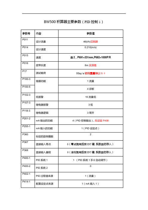
BW500积算器主要参数(PID控制1)
PID控制1用的是mA输入1及mA输出2,这是固定的。
mA输出1,在主板的端子21/22,其余在IO板上mA输出2端子1/2,mA输出3端子3/4,mA输入1端子5/6 ,mA输入2端子7/8。
2010-5-14:5个继电器的报警设定100(1-流量;2-载荷;3-速度;4-诊断),118设为2 RLY1端子47/48,RLY2端子49/50,RLY3端子51/52,RLY3端子53/54,RLY5端子55/56 [注]:P400-1必须先设为1(即手动),跑完零点和量程,转换开关切到远方时才设为2
BW500积算器主要参数(PID系统2)
*的表示参数与PID控制1有差别。
PID控制2用的是mA输入2及mA输出3,这是固定的。
mA输出1,在主板的端子21/22,其余在IO板上mA输出2端子1/2,mA输出3端子3/4,mA输入1端子5/6 ,mA输入2端子7/8。
2010-5-14:5个继电器的报警设定100(1-流量;2-载荷;3-速度;4-诊断),118设为2
RLY1端子47/48,RLY2端子49/50,RLY3端子51/52,RLY3端子53/54,RLY5端子55/56 [注]:P400-2必须先设为1(即手动),跑完零点和量程,转换开关切到远方时才设为2。
- 1、下载文档前请自行甄别文档内容的完整性,平台不提供额外的编辑、内容补充、找答案等附加服务。
- 2、"仅部分预览"的文档,不可在线预览部分如存在完整性等问题,可反馈申请退款(可完整预览的文档不适用该条件!)。
- 3、如文档侵犯您的权益,请联系客服反馈,我们会尽快为您处理(人工客服工作时间:9:00-18:30)。
不对称重传 感器配平, 将影响皮带 称量系统
双传感器皮 带称
称重传感器 A
进入P295
标定砝码
按
称重传感器 B
如果在P003 里称重传感 器的数量设 置 为4只,本 项选2
按
如果有四只 称重传感 器,则继续 按
按
按
配平后需要对称重传感器进行零点 和
按
按
称重传感器 的配平现在 完成,下面 进行零点和 量程的标定 。
按
向下移动
直接存取: 按
按
或按
修改参数 值:
按
例如:从 P001 到 P002
例如:从 P002 到 P001
例如:进入 P011,设计 流量
可以直接索 引参数 例如:进入 P940-2,传 感器B的 mV信号
从浏览状态
如果按 ENTER后 编辑状态没 有使能, 需要进入@ P001解除安 全锁定
防护:
4X / NEMA 4X / IP 65
285mm宽 x 209mm高 x 92mm厚 (11.2”宽 x 8.2”高 x 3.6”厚)
编程: 显示: 内存: 输入:
输出:
聚碳酸酯
通过局部键 盘或 Dolphin Plus接口
5x7点矩阵 液晶显示, 2行,每行 40个字符
程序存储在 ROM闪存 中 也可存在有 电池的 RAM中, 电池: P/N 20200035, 3V锂电,5 年寿命
如果皮带称 * 与BW500
断开 ·BW500
·增加接线: BW500的 ·12端子接称 BW500的 13端子接称 ·“黑”
双传感器配 置:
传感器A
传感器B
红黑绿 白绿白
如果皮带称 * 与BW500
断开 ·BW500
·增加接线: BW500的 ·12端子接称 BW500的 13端子接称 ·“黑”
四只传感器 配置:
传感器A
传感器B
传感器C 传感器D
红黑 绿白绿白
红黑绿白绿 白
如果皮带称 * 与BW500
断开 ·BW500
·增加接线: BW500的 ·12端子接称 BW500的 13端子接称 ·“黑”
速度传感 器:
恒速(无传 感器)
如果速度传 感器没有安 装,则必须 将BW500 的17/18端 子短接。
独立 24VDC, 50mA,带 供电输出: 短路保护
LVDT接口 卡:
用于LVDT 形式的称量 设备的接口
重量:
2.6Kg
外开尺寸:
安装时注意 保护接地
可选插件: SmartLinx ®模板: BW500可 以插入可选 件 SmartLinx® 通讯模板, 以提供通讯 可以单独定 货。 如果你准备 安装或更换 SmartLinx® 模板,请按 下面步骤: 安装:
辅助输出 点:24V 50mA 带 短路保护 模拟量输 入:200Ω 模拟量输 入:200Ω 模拟量输 出:750Ω 模拟量输 出:750Ω
安装、更换 电池:
注意:安装或更换电池时必须断开电源, BW500在工作时禁止更换电池。
内存电池的 使用寿命为 5年,5年后 请更换电池 。 在电池取出 后,主板电 容将提供20 分钟时间以 保存内存里 的内容
1个对流量
、载荷、和
速度可行进
编程的0/4-
mA:
20mA,
光电隔离
分辨率达到
20mA的
0.1%
最大750欧
姆输入负载
详见可选
mA I/O板
电缆:
称重传感 器:
10VDC带 补偿供电电 源,最多4 只传感器, 最大150mA 。
速度传感 器:
12VDC, 最大150mA 供电
远程累积 1:
远程累积 2:
4芯屏蔽电 缆,最长 150m 6芯屏蔽电 缆,最长 300m
6芯屏蔽电 缆,最长 150m 8芯屏蔽电 缆,最长 300m
速度传感 3芯屏蔽电
器:
缆,300m
1对双绞线/ 屏蔽电缆, 自动清零: 最长300m 1对双绞线/ 屏蔽电缆, 远程累积: 最长301m
可选件: 速度传感 器: Dolphin Plus: SmartLinx 倾斜补偿: mA I/O 板:
程序化
初次显示提 示,用户选 择首选语言
按 例:选择“ 砝码”(随 称提供)
按
例:传感器 器数量,选 择“2”
按 例:制式, 选“2”, 公制
按 例:流量单 位,选“1 ”
按
默认日期
按
例:输入当
按
前日期
设定24小时 制时间
按
按
按
按
按
按
如果速度是 恒定的,将 显示 'Jumpered' ,按 继续 按
16/17端子 也可以接干 接点或晶体 ·管开关
也可以接其 它形式的速 ·度传感器 辅助输入: 用户可以自 定义的输入 点: 可以是干接 点或晶体管 开关
自动清零:
RS-232接 口1:
接一个干接 点
计算机和调 制解调器接 口:
9针 计算机
Modem
25针
远程累积显 示:
模拟量输 出:
最大30V 最大240V
接点闭合周 期10- 3集0电0m极s 开路 开关额定电 压 30VDC, 最大100mA 接点闭合周 期10- 3集0电1m极s 开路 开关额定电 压 30VDC, 最大100mA
继电器输 出:
5个报警/控 制继电器, 额定5A
250VAC
1个传感 器:
无补偿:
2/4传感 器:
带补偿:
无补偿:
带补偿: 对于4只传 感器的称, 可用两个单 独的双传感 器专用电 缆,
按速度传感 器上的铭牌 输入传感器 数据,仪表 自动计算并 输入P015
例:恒速, 每米100.3 个脉冲
出厂设定的 皮带长度
例:皮带长 度为25m 出厂设定的
如果选择 Ecal-模拟:
按
参考P693- P699
按
这个值为原 设计数据
标定负载应 小于设计负 载(P952) 。
例:标定负 载25kg/m
按
按
与先前零点 的偏移 因为这是首 次操作,所 以偏移为0 新的零点 数,按 ENTER确
零点数为 例: 551205
当前量程数
量程数正在 计算
量程标定依 靠皮带称的 速度P014、 长度P016、 和旋转P360 如果
动态皮带称 或有1,2, 4只传感器 应用范围: 的称量设备 装有LVDT 的设备称, 需要可选接 口板。
精度:
0.10%
分辨率:
0.02%
安装环境: 安装地点: 户内/户外
海拔: 最-2大0 -25000°mC
(-5 - 122 °
环境温度: F)
相对湿度: 与户外相同
安装种类: II
污染指数:
4
功能简 介:
BW500性 能特点:
ACCUMASS BW500 操作说明书
BW500是以微处理器为核心而设计的积分仪,可以配合西门子及同种类型的皮带称或配料称使用。 积分仪处理来自皮带称的速度与重量信号,经过处理后在LCD上显示,或输出模拟量mA信号、继电 器报警输出及远程显示。 BM500支持Dolphin Plus软件及Modbus协议,带二个RS232各RS485接口 BW500支持SmartLinx®通讯系统
端口 3
显示屏
电压选择 开关
保险
所有的配线 必须适应 250V AC绝 缘标准 两个相邻继 电器的工作 电压不应超 过250V AC
系统接口:
皮带称 速度传感器 模拟量输出 模拟量输出 模拟量输入
单传感器配 置:
继电器输出 辅助输入
远程累积显 示
总线通讯
通讯端口
西门子皮带 称
称重传感器
红黑 绿白
输入当前时 间 14:41 工厂设定流 量值
例:流量设 为100t/h 工厂设定速 度
例:速度设 为0.8m/s 例:速度设 为0
输入适当数 值后,返回 P015
按 这个值可以 按原设计, 也可以通过 计算得出。 关于手动或 自动计算, 参考P690
按
按
如果在P002 选择了2- 链码,将显 示:
输入一个新
按
值
复位参数 值:
对于P001到P017,修改一个参数后 会进入到下一个必需的参数
按
从编辑状态
输入清除功
按
能
被复位到工 厂设定值 例如: 0.00kg/h
运行模式: 为了BW500在运行状态下能运行,必须要对它进行初始化程序以建立一个基本 的运行参数。
初次启动 上电
上电 程序化 称重传感器 配平 零点和量程 的标定
继电器输 出:
继电器输出 为常开结 点,额定电 压: 250V,5A
RS-485接 口:
最大负载: 750Ω
RS-232接 口3:
带RJ-11插 头的标准电 缆
RJ-11适配 器/9针插头 (公)
电源选择开 关:
注意:必须 接15A的断 路器或保险
9针插头 (母)
模拟量I/O 模板:
100 / 115 / 200 / 230V 50 / 60 Hz 通过选择开 关选择电压
累积清零
程序模式:
概要:
BW500有两种运行模式:“run”和“program”即“运行”和“编程”。 上电时其处于“编程”模式下 进行入编程 状态时,用 户可以根据 实际需求修 改参数值
编程状态:
浏览
进入编程状 态:
按
编辑
显示参数的 缺省值 例如:P001 是初次启动 的默认参数
选择参数:
按