传感器文档
精品文档-传感器原理及应用(郭爱芳)-第12章

第12章 智能传感器 图12.2 DTP型智能式压力传感器的结构
第12章 智能传感器
12.2.1 基本传感器 1. 传感器的主要技术要求 (1) 具有将被测量转换为后续电路可用信号的功能; (2) 转换范围与被测量实际变化范围一致,转换精度符
合在整个系统的总精度要求下而分配给传感器的精度指标(一 般应优于系统精度的十倍左右),转换速度应符合整机要求;
分析与处理功能,可完成非线性、温度、噪声、响应时间以及 零点漂移等误差的自动修正或补偿,提高测量准确度;
(2) 自校准、自诊断功能:实时进行系统的自检和故障 诊断,在接通电源时进行开机自检,在工作中进行运行自检, 自动校准工作状态,自行诊断故障部位,提高工作可靠性;
(3) 自适应、自调整功能:根据待测量的数值大小和工 作条件的变化情况,自动调整检测量程、测量方式、供电情况、 与上位机的数据传送速率等,提高检测适应性;
(4) 电源引起的失调:电源电压变化1%所引起放大器的 漂移电压值。一般数据采集系统的前置放大器常用稳压电源供 电,该指标是设计稳压电源的主要依据。
第12章 智能传感器
1. 仪用放大器 仪用放大器常采用三运放对称结构且具有较高的输入阻抗 和共模抑制比的单片集成放大器,只需外接一个电阻即可设定 增益,如美国BB(Burr Brown)公司生产的INA114, 美国 AD(Analog Devies)公司生产的AD521、AD524、AD8221等。 INA114是一种通用的仪用放大器,尺寸小、精度高、价格低 廉,可用于电桥、热电偶、数据采集以及医疗仪器等,其内部 电路如图12.3所示。
(3) 满足被测介质和使用环境的特殊要求,如耐高温、 耐高压、防腐、抗振、防爆、抗电磁干扰、体积小、质量轻和 不耗电(或耗电少)等;
高温测温传感器

高温测温传感器高温测温传感器文档一、引言高温测温传感器是一种能够测量高温环境中温度的传感器。
高温环境中的温度测量对于许多工业领域来说非常关键,例如钢铁冶炼、玻璃生产和石油化工等行业。
本文档将介绍高温测温传感器的工作原理、应用领域和未来发展趋势。
二、工作原理高温测温传感器利用电阻、热电效应或红外辐射等原理来测量高温环境中的温度。
其中最常用的是热电阻温度传感器和红外温度传感器。
1. 热电阻温度传感器热电阻温度传感器是利用材料的电阻随温度的变化来测量温度的。
常见的热电阻材料有铂、镍和铜镍合金等。
当热电阻传感器暴露在高温环境中时,传感器的电阻会随着温度的升高而增加。
通过测量电阻的变化,可以计算出环境的温度。
2. 红外温度传感器红外温度传感器是利用物体发射、吸收和传输红外辐射的原理来测量温度的。
它可以测量目标表面的红外辐射功率,并将其转换为相应的温度值。
红外温度传感器通常包括一个红外探测器和一个信号处理单元。
探测器接收红外辐射,并将其转换为电信号,信号处理单元则将电信号转换为温度值。
三、应用领域高温测温传感器在许多行业中广泛应用,以下是其中一些典型的应用领域:1. 钢铁冶炼钢铁冶炼是一个高温环境下的过程,需要精确测量炉温以确保生产质量和工艺控制。
高温测温传感器可以安全、准确地测量炉内温度,帮助提高生产效率和生产质量。
2. 玻璃生产玻璃生产过程需要在高温下进行,需要对炉温进行实时监控。
高温测温传感器可以快速响应温度变化,并提供准确的温度数据,帮助调整生产参数以获得所需的玻璃质量。
3. 石油化工石油化工行业也是一个高温环境下的行业,需要对储罐、反应器和管道等设备的温度进行监测。
高温测温传感器可以在极端条件下提供可靠的温度测量,确保设备的安全运行。
其他行业中也广泛使用高温测温传感器,例如航空航天、电力、汽车和船舶等。
四、未来发展趋势随着科技的进步和工业需求的增加,高温测温传感器也在不断发展,有以下几个趋势:1. 高温测温传感器的测量范围将进一步提高。
传感器产品说明书

传感器产品说明书
一、产品简介
传感器是一种检测装置,能感受到被测量的信息,并能将感受到的信息,按一定规律变换成为电信号或其他所需形式的信息输出,以满足信息的传输、处理、存储、显示、记录和控制等要求。
二、产品特点
1 .高精度:传感器采用先进的传感技术,能够准确检测被测物体的位置和状态变化,具有高精度的测量结果。
2 .快速响应:传感器具有快速的响应速度,能够在短时间内对被测物体的变化做出反应,适合用于需要快速响应的场合。
3 .稳定性好:传感器经过严格的质量控制和性能测试,能够在长时间内保持稳定的性能表现,减少误差和故障率。
4 .易于安装:传感器设计简洁,安装方便,能够快速集成到各种设备和系统中。
5 .可靠性高:传感器采用耐用的材料和结构设计,能够在恶劣的环境条件下稳定工作,保证测量结果的可靠性和准确性。
三、使用说明
1 .安装:请根据产品手册中的安装指南正确安装传感器,确保传感器与被测物体接触良好,无松动现象。
2 .电源:请使用与传感器配套的电源,并确保电源电压稳定。
3 .信号输出:根据需要选择合适的信号输出方式,如模拟信号、数字
信号等。
4 .维护:定期对传感器进行清洁和维护,以保证其性能和使用寿命。
四、注意事项
1.请勿在超过规定的温度、湿度、压力等环境下使用传感器。
5 .请勿在有磁场干扰、电气噪声等环境下使用传感器。
6 .请勿在有机械振动、冲击的环境下使用传感器。
耐高温测距传感器

耐高温测距传感器耐高温测距传感器文档一、引言耐高温测距传感器是一种能够在高温环境下可靠测量距离的传感器设备。
它能够广泛应用于各种高温环境下的测距应用,如钢铁冶金、化工、航天航空等行业。
本文档将对耐高温测距传感器的工作原理、性能特点、应用领域以及未来发展进行详细介绍。
二、工作原理耐高温测距传感器利用红外激光或超声波等技术原理进行测量。
它通过向目标物体发射红外激光或超声波信号,并接收反射信号计算出距离。
传感器内部包含一个高温耐受的光学组件和电子电路,可在高温环境下稳定工作。
三、性能特点1. 高温耐受能力:耐高温测距传感器能够在高温环境下长时间稳定工作,通常能够耐受高达500°C的温度。
2. 高精度测量:传感器具备高度精确的测量能力,能够实时测量距离,并提供稳定的数据。
3. 耐腐蚀性能:传感器表面涂有特殊材料,能够在腐蚀性气体环境下长时间使用,并保持精确的测量结果。
4. 快速响应:传感器能够在纳秒级别快速响应,实时获取目标物体距离的变化。
5. 兼容性:耐高温测距传感器与各种控制系统兼容,可与PLC、SCADA系统等无缝集成。
四、应用领域1. 钢铁冶金:在高温炉炼钢和铁的过程中,耐高温测距传感器可用于测量炉内物料的高度,以控制炉料的投入和排出。
2. 化工:在化工生产过程中,传感器可用于测量反应釜内液位、槽内物料的液面高度等,以控制反应过程的稳定性。
3. 航天航空:在航天器发射和着陆过程中,传感器可用于测量离地面或着陆平台的距离,以确保航天器的安全着陆。
4. 汽车制造:传感器可用于汽车烤漆过程中对车体的距离测量,确保喷漆的均匀性,提高产品质量。
五、未来发展随着科技的发展和应用需求的不断增加,耐高温测距传感器在未来将迎来更广阔的应用前景。
未来的耐高温测距传感器将更加精确、灵敏,并能够在更高的温度范围内工作。
同时,传感器的体积将进一步缩小,使其可以应用于更多高温环境下的实际场景。
六、结论耐高温测距传感器是一种能够在高温环境下可靠测量距离的传感器设备。
智能温湿度传感器文档说明书

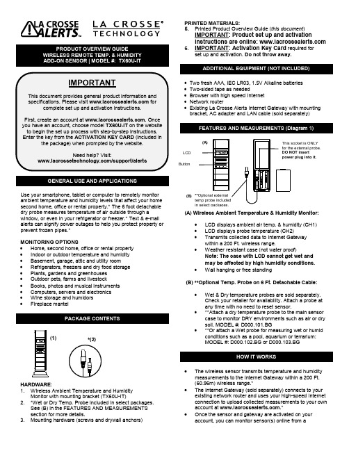
GENERAL USE AND APPLICATIONSUse your smartphone, tablet or computer to remotely monitor ambient temperature and humidity levels that affect your home second home, office or rental property.* The 6 foot detachable dry probe measures temperature of air outside through a window, or even in your refrigerator or freezer.* Text & e-mail alerts can signify power outages to help you protect property or prevent frozen pipes.*MONITORING OPTIONS•Home, second home, office or rental property•Indoor or outdoor temperature and humidity •Basement, garage, attic and utility room •Refrigerators, freezers and dry food storage•Plants, gardens and greenhouses•Outdoor pets, farms and livestock•Books, photos and musical instruments•Computers, servers and electronics•Wine storage and humidors•Fireplace mantelPACKAGE CONTENTSHARDWARE:1. Wireless Ambient Temperature and HumidityMonitor with mounting bracket (TX60U-IT)2. *Wet or Dry Temp. Probe included in select packages.See (B) in the FEATURES AND MEASUREMENTSsection for more details.3. Mounting hardware (screws and drywall anchors) PRINTED MATERIALS:5. Printed Product Overview Guide (this document)IMPORTANT: Product set up and activationinstructions are online: 6. IMPORTANT: Activation Key Card required forset up and activation. Do not throw away.•Two fresh AAA, IEC LR03, 1.5V Alkaline batteries•Two-sided tape as needed•Browser with high speed Internet•Network router•Existing La Crosse Alerts Internet Gateway with mounting bracket, AC adapter and LAN cable (sold separately)FEATURES AND MEASUREMENTS (Diagram 1)(A) Wireless Ambient Temperature & Humidity Monitor:•LCD displays ambient air temp. & humidity (CH1)•LCD displays probe temperature (CH2)•Transmits collected data to Internet Gatewaywithin a 200 Ft. wireless range.•Weather resistant case (not water proof)Note: The case with LCD cannot get wet andmay be affected by high humidity conditions.•Wall hanging or free standing(B) **Optional Temp. Probe on 6 Ft. Detachable Cable:•Wet & Dry temperature probes are sold separately.Check your retailer for availability. Attach a probe atany time with no need to reset sensor.•**Attach a dry temperature probe to the main sensorcase to monitor DRY environments such as air or drysoil. MODEL #: D000.101.BG•**Or attach a Wet probe for measuring wet or humidconditions such as a pool, aquarium or terrarium:MODEL #: D000.102.BG or D000.103.BGHOW IT WORKS•The wireless sensor transmits temperature and humiditymeasurements to the Internet Gateway within a 200 Ft.(60.96m) wireless range.*•The Internet Gateway (sold separately) connects to yourexisting network router and uses your high-speed Internetconnection to upload collected measurements to your ownaccount at .*•Once the sensor and gateway are activated on youraccount, you can monitor sensor(s) online from a(1) *(2)(B)**Optional externalin select packages.smartphone, tablet or computer, and set up custom e-mail/text alerts*.•Add up to 5 sensors (sold separately) per Internet gateway (sold separately) to monitor additional areas.1. Begin set up near your existing network router and a computer with high-speed Internet access.2. Unpack package contents and insert temp. probe (if it’s included) into the TX60U-IT case (see diagram 1).1. Locate the Activation Key Card in the package for setupinstructions and the Activation Key . The Activation Key is necessary to activate your sensor with Internet Gateway (sold separately). Keep your Activation Card for reference. 2. Visit with your Activation KeyCard to create your account and activate the product.ACTIVATION INFORMATION:THE INCLUDED ACTIVATION KEY is good for1 year of ENHANCED SERVICE with early warning text & e-mail alerts, plus 4 more years of BASIC SERVICE for standard remote monitoring.Lost your Activation Key Card?Contact Customer Support:/support/alerts Phone: (608) 785-7920Once the sensor is activated and building a measurement log, you can download the data as a comma separated values (CSV) file. You must use an application such as Microsoft Excel® or Google Docs® that supports comma separated values (CSV) formatted files to view the table data.• Select a location protected from water and otherprecipitation. The case is water resistant, not water proof. • Place the sensor in a dry, shaded area. Avoid locations with direct sun, to prevent inaccurate readings.• Fog and mist will not harm the sensor but direct precipitation must be avoided.• Note: Exposing the sensor case to extreme humidity may temporarily disrupt data. The sensor case reads humidity, but should not be submerged in water.• Select a location within range of the Internet gateway (see “IMPORTANT SETUP & OPERATION NOTES”).• IMPORTANT: Before permanently mounting…Test sensor in the desired mounting location for at least 1 hour to confirm good reception. Confirm consistent readings on your account at before permanentlymounting. Move the sensor closer to the Internet Gateway if the signal is lost or not received. • Mount the sensor after the activation process (see “SETUP AND ACTIVATION”). MOUNT TO WALL WITH SCREWS1. Remove the mounting bracket2. Place bracket over the desired location.3. Mark mounting surface with a pencil through the 2 holes of the bracket.4. Screw bracket onto surface and tighten screws to bracket.5. Insert the sensor back into the bracket.FREE STANDINGAttach the mounting bracket to the bottom or top of the sensor and place it on any flat surface.PLACEMENT OF TEMPERATURE PROBE (Optional)• Confirm that the end of the probe cable is secured in the socket inside the sensor (See Diagram 1).• Insert the dry temp. probe on 6 Ft. cable into a refrigerator or freezer, or dry soil, etc. for a separate reading of air or soil temperature. The dry temp. probe is not for use in water. • **An optional wet probe should be used to measure wet environments (sold separately). Check your retailer for availability: MODEL #: D000.102.BG• Loosely coil and secure extra cord with a twist tie or secure with tape (not included).• The sensor has a wireless range of 200 feet (60.96 m). The 200 ft. range equates to open air with no obstructions, and that radio waves DO NOT curve around objects. Actualtransmission range will vary depending on what is in the path of the signal. Each obstruction (roof, walls, floors, ceilings, etc.) will effectively cut signal range in half.• Metal, stucco, and some types of glass can reduce signal range by as much as ¾ or more, compared to the ½ reduction typical of most obstructions. It is possible toreceive a signal through these materials, however maximum range will be reduced due to their tendency to absorb or reflect a much larger portion of the sensor’s signal.• The sensor measures and updates the temperature and humidity on the LCD every 6 seconds.Note : The new measurement is reported to your account at intervals that you select using your online account.1. Remove the battery cover by sliding the cover down.2. Observing the correct polarity install 2-AAA batteries. The batteries will fit tightly (to avoid start-up problems make sure they do not spring free).3. Do not mix old and new batteries.4. Do not mix alkaline, lithium, standard or rechargeable batteries.5. Replace the battery cover by sliding upwards and check that it is securely fitted.• Low battery icon appears on LCD when batteries are low. • You will receive an e-mail or mobile text message alert when the battery power of the sensor is low. Change the batteries immediately.Note: The LED light turns ON briefly after changing batteries. The LED light turns OFF when not needed to save battery power. The previously stored information in the temperature and humidity sensor will not be affected or cancelled while you change the batteries.• Avoid extreme temperatures, vibration and shock. • Clean the sensor with a soft, damp cloth. Do not use solvents or scouring agents.• Do not submerge the sensor case in water. • Do not kink the 6 ft. sensor cable.• Secure the 6 ft. cable to avoid tripping hazards.• Immediately remove all low powered batteries to avoid leakage and damage.• Opening the casings invalidates the warranty. Do not try to repair the unit. Contact La Crosse Technology® for repairs.Temperature range:-40°F to 140°F with 0.2°F resolution“OFL” displayed if outside this range. Humidity measuring range: 3% to 99% Transmission range:200 feet (60.96 m) in open spaceTemp. Probe 6 Ft. Cable: Channel 2:-40°F to 140°F with 0.2°F OPTIONAL resolution “OFL” displayed if outside this range, and displayed “nC” if probe is not connected.Sensor battery power 2 x AAA Alkaline, IEC LR03, 1.5V Internet gateway power: AC adapter (included) Battery life cycle:Approximately 24 monthsTX60U-IT size: 5.23" H x 0.76" W x 1.44" DLa Crosse Technology, Ltd provides a 1-year limited warrantyon this product against manufacturing defects in materials and workmanship.This limited warranty begins on the original date of purchase, is valid only on products purchased and used in North America and only to the original purchaser of this product. To receive warranty service, the purchaser must contact La Crosse Technology, Ltd for problem determination and serviceprocedures. Warranty service can only be performed by a La Crosse Technology, Ltd authorized service center. Theoriginal dated bill of sale must be presented upon request as proof of purchase to La Crosse Technology, Ltd or La Crosse Technology, Ltd’s authorized service center.La Crosse Technology, Ltd will repair or replace this product, at our option and at no charge as stipulated herein, with new or reconditioned parts or products if found to be defective during the limited warranty period specified above. All replaced parts and products become the property of La Crosse Technology, Ltd and must be returned to La Crosse Technology, Ltd. Replacement parts and products assume the remainingoriginal warranty, or ninety (90) days, whichever is longer. La Crosse Technology, Ltd will pay all expenses for labor and materials for all repairs covered by this warranty. If necessary repairs are not covered by this warranty, or if a product isexamined which is not in need or repair, you will be charged for the repairs or examination. The owner must pay any shipping charges incurred in getting your La Crosse Technology, Ltd product to a La Crosse Technology, Ltd authorized service center. La Crosse Technology, Ltd will pay ground returnshipping charges to the owner of the product to a USA address only.Your La Crosse Technology, Ltd warranty covers all defects in material and workmanship with the following specifiedexceptions: (1) damage caused by accident, unreasonable use or neglect (including the lack of reasonable and necessary maintenance); (2) damage occurring during shipment (claims must be presented to the carrier); (3) damage to, ordeterioration of, any accessory or decorative surface; (4)damage resulting from failure to follow instructions contained in your owner’s manual; (5) damage resulting from theperformance of repairs or alterations by someone other than an authorized La Crosse Technology, Ltd authorized service center; (6) units used for other than home use (7) applications and uses that this product was not intended or (8) the products inability to receive a signal due to any source of interference.. This warranty covers only actual defects within the product itself, and does not cover the cost of installation or removal from a fixed installation, normal set-up or adjustments, claims based on misrepresentation by the seller or performance variations resulting from installation-related circumstances.LA CROSSE TECHNOLOGY, LTD WILL NOT ASSUMELIABILITY FOR INCIDENTAL, CONSEQUENTIAL, PUNITIVE, OR OTHER SIMILAR DAMAGES ASSOCIATED WITH THE OPERATION OR MALFUNCTION OF THIS PRODUCT. THIS PRODUCT IS NOT TO BE USED FOR MEDICAL PURPOSES OR FOR PUBLIC INFORMATION. THIS PRODUCT IS NOT A TOY. KEEP OUT OF CHILDREN’S REACH.This warranty gives you specific legal rights. You may also have other rights specific to your State. Some States do not allow the exclusion of consequential or incidental damages therefore the above exclusion of limitation may not apply to you. For warranty work, technical support, or information, please contact:La Crosse Technology, Ltd2817 Losey Blvd. S. La Crosse, WI 54601/support/alertsLost your Activation Key Card?Contact Customer Support:/support/alerts Phone: (608) 785-7920* Disclaimers: La Crosse Technology, LTD. (“La Crosse”) provides various alert and monitoring services to aid users. (1) Service providers may charge users for alert services. Standard messaging and data rates apply and will be billed to the customer’s wireless account. Customers may be unable to receive text messaging or data service in some areas due to unavailability of service. (2) La Crosse shall not be liable for accuracy, usefulness or availability of data transmitted via the service. Users are solely responsible for damages to persons or property by service use.All rights reserved. This handbook must not be reproduced in any form, even in excerpts, or duplicated or processed using electronic, mechanical or chemical procedures without written permission of the publisher.This handbook may contain mistakes and printing errors. The information in this handbook is regularly checked and corrections made in the next issue.We accept no liability for technical mistakes or printing errors, or their consequences. All trademarks and patents are acknowledged.5,978,738 6,076,044 6,597,990This device complies with part 15 of the FCC rules. Operation is subject to the following two conditions:1) This device may not cause harmful interference.2) This device must accept any interference received,including interference that may cause undesired operation.。
温湿度传感器DHT22说明文档

数字温湿度传感器AM2302小体积AM2302大体积AM2302►相对湿度和温度测量►全部校准,数字输出►卓越的长期稳定性►无需额外部件►超长的信号传输距离►超低能耗►4引脚安装►完全互换AM2302产品概述AM2302数字温湿度传感器是一款含有已校准数字信号输出的温湿度复合传感器。
它应用专用的数字模块采集技术和温湿度传感技术,确保产品具有极高的可靠性与卓越的长期稳定性。
传感器包括一个电容式感湿元件和一个NTC 测温元件,并与一个高性能8位单片机相连接。
因此该产品具有品质卓越、超快响应、抗干扰能力强、性价比极高等优点。
每个AM2302传感器都在极为精确的湿度校验室中进行校准。
校准系数以程序的形式储存在OTP内存中,传感器内部在检测信号的处理过程中要调用这些校准系数。
单线制串行接口,使系统集成变得简易快捷。
超小的体积、极低的功耗,信号传输距离可达20米以上,使其成为各类应用甚至最为苛刻的应用场合的最佳选则。
产品为4针单排引脚封装。
连接方便,特殊封装形式可根据用户需求而提供。
应用领域►暖通空调►测试及检测设备►汽车►数据记录器►消费品►自动控制►气象站►家电►湿度调节器►医疗1、传感器性能说明2、采样周期不得低于最小值,否则会引起错误3、接口说明建议连接线长度短于20米时用5K 上拉电阻,大于20米时根据实际情况使用合适的上拉电阻AM2302的接线图如下图所示。
参数条件Min Typ Max 单位湿度分辨率0.1%RH 16Bit 重复性±0.3%RH 精度25℃±2%RH -2-200-80℃±2%RH 互换性可完全互换采样周期2S 响应时间1/e(63%)25℃,1m/s 空气<5S 迟滞<±0.3%RH 长期稳定性典型值<±0.5%RH/yr温度分辨率0.1℃16Bit重复性±0.0.22℃精度<±0.5℃量程范围-4080℃响应时间1/e(63%)620S3、电源引脚AM2302的供电电压为3.3-6V。
精品文档-传感器原理及应用(郭爱芳)-第3章

第3章 电阻式传感器 图3.3 金属电阻应变片的种类
第3章 电阻式传感器
4) 薄膜式应变片 薄膜式应变片是利用真空蒸镀、沉积或溅射等方法在绝缘 基底上制成各种形状的薄膜敏感栅,膜厚小于1 μm。这种应 变片的优点是应变灵敏系数大,允许电流密度大,可以在- 197~317℃温度下工作。
第3章 电阻式传感器
在应变极限范围内,金属材料电阻的相对变化量与应变成 正比,即
ΔR R
S0
(3.5)
第3章 电阻式传感器
3.1.2 金属电阻应变片 1. 应变片的结构及测量原理 金属电阻应变片简称应变片,其结构大体相同,如图3.2
所示。金属电阻应变片由基底、敏感栅、覆盖层和引线等部分 组成。
第3章 电阻式传感器 图3.2 金属电阻应变片的结构
第3章 电阻式传感器
图3.1所示为金属电阻丝的电阻应变效应原理图。长度为 L、截面积为A、电阻率为ρ的金属电阻丝,在未受外力作用时 的原始电阻值为
R L
A
(3.1)
图3.1 金属电阻丝的电阻应变效应
第3章 电阻式传感器
当受到轴向拉力F作用时,其长度伸长ΔL,截面积相应减 小ΔA,电阻率ρ则因晶格变形等因素的影响而改变Δρ,故 引起电阻变化ΔR。对式(3.1)全微分可得
第3章 电阻式传感器 图3.4 应变片轴向受力及横向效应
第3章 电阻式传感器
2) 横向效应 由于应变片的敏感栅是由多条直线段和圆弧段组成,若该 应变片受轴向应力而产生纵向拉应变εx时,则各直线段的电 阻将增加。但在圆弧段,如图3.4(b)所示,除产生纵向 拉应变εx外,还有垂直方向的横向压应变εy=-εx,沿各微 段轴向(即微段圆弧的切向)的应变在εx和εy之间变化。在圆 弧段两端的起、终微段,即θ=0°和θ=180°处,承受+εx应 变;而在θ=90°的微段处,则承受εy=-εx应变。因此,将 金属电阻丝绕成敏感栅后,虽然长度不变,应变状态相同,但 应变片敏感栅的灵敏系数S比电阻丝的灵敏系数S0低,这种现 象称为应变片的横向效应。
- 1、下载文档前请自行甄别文档内容的完整性,平台不提供额外的编辑、内容补充、找答案等附加服务。
- 2、"仅部分预览"的文档,不可在线预览部分如存在完整性等问题,可反馈申请退款(可完整预览的文档不适用该条件!)。
- 3、如文档侵犯您的权益,请联系客服反馈,我们会尽快为您处理(人工客服工作时间:9:00-18:30)。
解:由题意知
则其动态误差
=7.76%
解:
所以,当ξ=0.14时
当ξ=0.7时
1—12 用一只时间常数t=0.318s的一阶传感器去测量周期分别为1s、2s和3s的正弦信号,问幅值相对误差为多少?
解:由一阶传感器的动态误差公式
(2) τ=1.4/4.2=1/3(s),
K=9.6/4.2=2.29(mV/Pa)。
1—7 已知一热电偶的时间常数t=10s,如果用它来测量一台炉子的温度,炉内温度在540℃至500℃之间接近正弦曲线波动,周期为80s,静态灵敏度K=1。试求该热电偶输出的最大值和最小值。以及输入与输出之间的相位差和滞后时间。
校准数据表
压 力
(MPa) 输 出 值 (mV)
第一次循环 第二次循环 第三次循环
正行程 反行程 正行程 反行程 正行程 反行程
0 -2.73 -2.71 -2.71 -2.68 -2.ቤተ መጻሕፍቲ ባይዱ8 -2.69
0.02 0.56 0.66 0.61 0.68 0.64 0.69
0.04 3.96 4.06 3.99 4.09 4.03 4.11
Ui =2U=2×2.19=4.38V≈4V
2—8 如果将120Ω的应变片贴在柱形弹性试件上,该试件的截面积S=0.5×10⁻⁴m2,材料弹性模量E=2×101lN/m2。若由5×104N的拉力引起应变片电阻变化为1.2Ω,求该应变片的灵敏系数K。
0.08 10.93 10.95 -0.02
0.10 14.45 14.38 0.07
所以,压力传感器的非线性误差为
可见,最小二乘法拟合直线比端点法拟合直线的非线性误差小,所以最小二乘法拟合更合理。
重复性误差dR和迟滞误差dH是一致的。
1—10 用一个一阶传感器系统测量100Hz的正弦信号时,如幅值误差限制在5%以内,则其时间常数应取多少?若用该系统测试50Hz的正弦信号,问此时的幅值误差和相位差为多?
0.06 7.40 7.49 7.43 7.53 7.45 7.52 7.47
0.08 10.88 10.95 10.89 10.93 10.94 10.99 10.93
0.10 14.42 14.42 14.47 14.47 14.46 14.46 14.45
(1)端点连线法
设直线方程为
解:依题意,炉内温度变化规律可表示为
x(t) =520+20sin(wt)℃
由周期T=80s,则温度变化频率f=1/T,其相应的圆频率 w=2pf=2p/80=p/40;
温度传感器(热电偶)对炉内温度的响应y(t)为
y(t)=520+Bsin(wt+j)℃
热电偶为一阶传感器,其响应的幅频特性为
0 -2.73 -2.71 0.02 -2.71 -2.68 0.03 -2.68 -2.69 0.01
0.02 0.56 0.66 0.10 0.61 0.68 0.07 0.64 0.69 0.05
0.04 3.96 4.06 0.10 3.99 4.09 0.10 4.03 4.11 0.08
0.10 14.45 14.45 0
所以,压力传感器的非线性误差为
¨求重复性误差:
压 力
(MPa) 输 出 值 (mV)
正行程 反行程
1 2 3 不重复误差 1 2 3 不重复误差
0 -2.73 -2.71 -2.68 0.05 -2.71 -2.68 -2.69 0.03
第一次循环 第二次循环 第三次循环 校验平均值
(设为y)
正行程 反行程 正行程 反行程 正行程 反行程
0 -2.73 -2.71 -2.71 -2.68 -2.68 -2.69 -2.70
0.02 0.56 0.66 0.61 0.68 0.64 0.69 0.64
0.04 3.96 4.06 3.99 4.09 4.03 4.11 4.04
解:满量程(F?S)为50﹣10=40(mV)
可能出现的最大误差为:
Dm=40′2%=0.8(mV)
当使用在 1/2和1/8满量程时,其测量相对误差分别为:
1—6 有两个传感器测量系统,其动态特性可以分别用下面两个微分方程描述,试求这两个系统的时间常数t和静态灵敏度K。
(1)
式中, y——输出电压,V;T——输入温度,℃。
(2)
式中,y——输出电压,mV;x——输入压力,Pa。
解:根据题给传感器微分方程,得
(1) τ=30/3=10(s),
K=1.5′10-5/3=0.5′10-5(V/℃);
相位差
= -0.29(rad)= -16.6°
第2章 电阻应变式传感器
2—5 一应变片的电阻R0=120Ω,K=2.05,用作应变为800μm/m的传感元件。(1)求△R与△R/R;(2)若电源电压Ui=3V,求其惠斯通测量电桥的非平衡输出电压U0。
解: 根据题意
(取等号计算)
解出
ωτ =0.3287
所以
=0.523ms
当用该系统测试50Hz的正弦信号时,其幅值误差为
相位差为
j=﹣arctan(wt)=﹣arctan(2π×50×0.523×10-3)=﹣9.3°
1—11一只二阶力传感器系统,已知其固有频率f0=800Hz,阻尼比z=0.14,现用它作工作频率f=400Hz的正弦变化的外力测试时,其幅值比A(w)和相位角j(w)各为多少;若该传感器的阻尼比z=0.7时,其A(w)和j(w)又将如何变化?
0.10 14.42 14.47 14.46 0.05 14.42 14.47 14.46 0.05
最大不重复误差为0.08 mV,则重复性误差为
¨求迟滞误差:
压 力
(MPa) 输 出 值 (mV)
第一次循环 第二次循环 第三次循环
正行程 反行程 迟滞 正行程 反行程 迟滞 正行程 反行程 迟滞
相应的时间滞后为
Dt =
1—8 一压电式加速度传感器的动态特性可以用如下的微分方程来描述,即
式中,y——输出电荷量,pC;x——输入加速度,m/s2。试求其固有振荡频率wn和阻尼比z。
解: 由题给微分方程可得
1—9 某压力传感器的校准数据如下表所示,试分别用端点连线法和最小二乘法求非线性误差,并计算迟滞和重复性误差;写出端点连线法和最小二乘法拟合直线方程。
t=0.318s
1—13 已知某二阶传感器系统的固有频率f0=10kHz,阻尼比z=0.1,若要求传感器的输出幅值误差小于3%,试确定该传感器的工作频率范围。
解:由f0=10kHz,根据二阶传感器误差公式,有
将z=0.1代入,整理得
因此,热电偶输出信号波动幅值为
B=20 A(w)=20 0.786=15.7℃
由此可得输出温度的最大值和最小值分别为
y(t)| =520+B=520+15.7=535.7℃
y(t)| =520﹣B=520-15.7=504.3℃
输出信号的相位差j为
j(ω)= -arctan(ω )= -arctan(2p/80′10)= -38.2°
0.06 7.40 7.49 0.09 7.43 7.53 0.10 7.45 7.52 0.07
0.08 10.88 10.95 0.07 10.89 10.93 0.04 10.94 10.99 0.05
0.10 14.42 14.42 0 14.47 14.47 0.0 14.46 14.46 0.0
0.02 0.56 0.61 0.64 0.08 0.66 0.68 0.69 0.03
0.04 3.96 3.99 4.03 0.07 4.06 4.09 4.11 0.05
0.06 7.40 7.43 7.45 0.05 7.49 7.53 7.52 0.04
0.08 10.88 10.89 10.94 0.06 10.95 10.93 10.99 0.04
《传感器与传感器技术》计算题
解题指导(仅供参考)
第1章 传感器的一般特性
1—5 某传感器给定精度为2%F?S,满度值为50mV,零位值为10mV,求可能出现的最大误差d(以mV计)。当传感器使用在满量程的1/2和1/8时,计算可能产生的测量百分误差。由你的计算结果能得出什么结论?
压 力
(MPa) 校验平均值
(mV) 直线拟合值
(mV) 非线性误差
(mV) 最大非线性误差
(mV)
0 -2.70 -2.77 0.07 -0.07
0.02 0.64 0.66 -0.02
0.04 4.04 4.09 -0.05
0.06 7.47 7.52 -0.05
最大迟滞为0.10mV,所以迟滞误差为
(2)最小二乘法
设直线方程为
y=a0+kx
数据处理如下表所示。
序号 1 2 3 4 5 6 ∑
x 0 0.02 0.04 0.06 0.08 0.10 0.3
y -2.70 0.64 4.04 7.47 10.93 14.45 34.83
0.06 7.40 7.49 7.43 7.53 7.45 7.52
0.08 10.88 10.95 10.89 10.93 10.94 10.99
