摩托罗拉 SPI 总线 协议规范
spi通信规范
竭诚为您提供优质文档/双击可除spi通信规范篇一:spi通讯协议介绍spi通讯协议介绍spiinterfacespi接口介绍spi是由美国摩托罗拉公司推出的一种同步串行传输规范,常作为单片机外设芯片串行扩展接口。
spi有4个引脚:ss(从器件选择线)、sdo(串行数据输出线)、sdi(串行数据输入线)和sck(同步串行时钟线)。
spi可以用全双工通信方式同时发送和接收8(16)位数据,过程如下:主机启动发送过程,送出时钟脉冲信号,主移位寄存器的数据通过sdo移入到从移位寄存器,同时从移位寄存器中的数据通过sdi移人到主移位寄存器中。
8(16)个时钟脉冲过后,时钟停顿,主移位寄存器中的8(16)位数据全部移人到从移位寄存器中,随即又被自动装入从接收缓冲器中,从机接收缓冲器满标志位(bF)和中断标志位(sspiF)置“1”。
同理,从移位寄存器中的8位数据全部移入到主寄存器中,随即又被自动装入到主接收缓冲器中.主接收缓冲器满标志位(bF)和中断标志位(sspiF)置“1”。
主cpu检测到主接收缓冲器的满标志位或者中断标志位置1后,就可以读取接收缓冲器中的数据。
同样,从cpu检测到从接收缓冲器满标志位或中断标志位置1后,就可以读取接收缓冲器中的数据,这样就完成了一次相互通信过程。
这里设置dspic30F6014为主控制器,isd4002为从器件,通过spi口完成通信控制的过程。
spi总线协议spi是一个环形总线结构,由ss(cs)、sck、sdi、sdo 构成,其时序其实很简单,主要是在sck的控制下,两个双向移位寄存器进行数据交换。
假设下面的8位寄存器装的是待发送的数据10101010,上升沿发送、下降沿接收、高位先发送。
那么第一个上升沿来的时候数据将会是sdo=1;寄存器=0101010x。
下降沿到来的时候,sdi上的电平将所存到寄存器中去,那么这时寄存器=0101010sdi,这样在8个时钟脉冲以后,两个寄存器的内容互相交换一次。
SPI通信协议(SPI总线)学习

SPI通信协议(SPI总线)学习各位读友大家好!你有你的木棉,我有我的文章,为了你的木棉,应读我的文章!若为比翼双飞鸟,定是人间有情人!若读此篇优秀文,必成天上比翼鸟!SPI通信协议(SPI总线)学习1、什么是SPI?SPI是串行外设接口(Serial Peripheral Interface)的缩写。
是Motorola 公司推出的一种同步串行接口技术,是一种高速的,全双工,同步的通信总线。
2、SPI优点支持全双工通信通信简单数据传输速率块3、缺点没有指定的流控制,没有应答机制确认是否接收到数据,所以跟IIC总线协议比较在数据可靠性上有一定的缺陷。
4、特点1):高速、同步、全双工、非差分、总线式2):主从机通信模式5、协议通信时序详解1):SPI的通信原理很简单,它以主从方式工作,这种模式通常有一个主设备和一个或多个从设备,需要至少4根线,事实上3根也可以(单向传输时)。
也是所有基于SPI的设备共有的,它们是SDI(数据输入)、SDO(数据输出)、SCLK(时钟)、CS(片选)。
(1)SDO/MOSI –主设备数据输出,从设备数据输入;(2)SDI/MISO –主设备数据输入,从设备数据输出;(3)SCLK –时钟信号,由主设备产生;(4)CS/SS –从设备使能信号,由主设备控制。
当有多个从设备的时候,因为每个从设备上都有一个片选引脚接入到主设备机中,当我们的主设备和某个从设备通信时将需要将从设备对应的片选引脚电平拉低或者是拉高。
2):需要说明的是,我们SPI通信有4种不同的模式,不同的从设备可能在出厂是就是配置为某种模式,这是不能改变的;但我们的通信双方必须是工作在同一模式下,所以我们可以对我们的主设备的SPI模式进行配置,通过CPOL(时钟极性)和CPHA(时钟相位)来控制我们主设备的通信模式,具体如下:Mode0:CPOL=0,CPHA=0Mode1:CPOL=0,CPHA=1Mode2:CPOL=1,CPHA=0Mode3:CPOL=1,CPHA=1时钟极性CPOL 是用来配置SCLK的电平出于哪种状态时是空闲态或者有效态,时钟相位CPHA是用来配置数据采样是在第几个边沿:CPOL=0,表示当SCLK=0时处于空闲态,所以有效状态就是SCLK处于高电平时CPOL=1,表示当SCLK=1时处于空闲态,所以有效状态就是SCLK处于低电平时CPHA=0,表示数据采样是在第1个边沿,数据发送在第2个边沿CPHA=1,表示数据采样是在第2个边沿,数据发送在第1个边沿例如:CPOL=0,CPHA=0:此时空闲态时,SCLK处于低电平,数据采样是在第1个边沿,也就是SCLK由低电平到高电平的跳变,所以数据采样是在上升沿,数据发送是在下降沿。
SPI总线协议介绍
SPI总线协议介绍 ⼀、概述 SPI = Serial Peripheral Interface,是串⾏外围接⼝设备,是⼀种⾼速,全双⼯,同步的通信总线。
常规只占⽤四根线,节约了芯⽚管脚,PCB的布局省空间。
优点: ⽀持全双⼯,push-pull的驱动性能相⽐open-drain信号完整性更好。
⽀持⾼速(100MHz以上)。
协议⽀持字节长不限于8bits,可根据应⽤特点灵活选择消息字长 硬件连接简单。
缺点: 相⽐I2C多两根线。
没有寻址机制,只能靠⽚选选择不同设备。
没有从设备接收ACK,主设备对于发送成功与否不得⽽知。
典型应⽤只⽀持单主控 相⽐RS232 RS485和CAN总线,SPI传输距离短 ⼆、硬件结构 SPI总线定义两个及以上设备间的数据通信,提供时钟的设备为主设备Master,接收时钟的设备为从设备Slave; 信号定义如下: SCK :Serial Clock 串⾏时钟 MOSI:Master Ouput,Slave Input 主发从收信号 MISO:Master Input,Slave Input主收从发信号 SS/CS:Slave Select⽚选信号 电路连接如下: 单个主设备和单个从设备: 单个主设备和多个从设备: 三、寄存器类型 摩托罗拉定义的SPI寄存器包括: SPI Control Register 1 控制寄存器1 SPI Control Register 2 控制寄存器2 SPI Baud Rate Register 波特率寄存器 SPI Status Register(SPISR) 状态寄存器(只读其余均可读可写) SPI Data Register(SPIDR)数据寄存器 通过往寄存器中写⼊不同的值,设置SPI模块的不同属性 四、SPI传输模式 SPI通信有四种模式,简单地讲就是设置SCLK时钟信号线的那种信号为有效信号 通过设置控制寄存器SPICR1中的CPOL和CPHA位,将SPI可以分成四种传输模式 时钟极性CPOL,即Clock Polarity,决定时钟空闲时状态电平。
SPI总线规范
SPI总线规范SPI是英文Serial Peripheral Interface的缩写,中文意思是串行外围设备接口,SPI是Motorola公司推出的一种同步串行通讯方式,是一种三线同步总线,因其硬件功能很强,与SPI有关的软件就相当简单,使CPU有更多的时间处理其他事务。
SPI概述SPI:高速同步串行口。
3~4线接口,收发独立、可同步进行.SPI,是英语Serial Peripheral interface的缩写,顾名思义就是串行外围设备接口。
是Motorola首先在其MC68HCX X系列处理器上定义的。
SPI接口主要应用在EEPROM,FLASH,实时时钟,AD转换器,还有数字信号处理器和数字信号解码器之间。
SPI,是一种高速的,全双工,同步的通信总线,并且在芯片的管脚上只占用四根线,节约了芯片的管脚,同时为PCB的布局上节省空间,提供方便,正是出于这种简单易用的特性,现在越来越多的芯片集成了这种通信协议,比如AT91RM9200.SPI总线系统是一种同步串行外设接口,它可以使MCU与各种外围设备以串行方式进行通信以交换信息。
外围设置FLASH RAM、网络控制器、LCD显示驱动器、A/D转换器和MCU等。
SPI总线系统可直接与各个厂家生产的多种标准外围器件直接接口,该接口一般使用4条线:串行时钟线(SCK)、主机输入/从机输出数据线MISO、主机输出/从机输入数据线MOSI和低电平有效的从机选择线SS(有的SPI接口芯片带有中断信号线INT或INT、有的SPI接口芯片没有主机输出/从机输入数据线MOSI)。
SPI的通信原理很简单,它以主从方式工作,这种模式通常有一个主设备和一个或多个从设备,需要至少4根线,事实上3根也可以(单向传输时)。
也是所有基于SPI的设备共有的,它们是SDI(数据输入),SDO(数据输出),SCK(时钟),CS(片选)。
(1)SDO –主设备数据输出,从设备数据输入(2)SDI –主设备数据输入,从设备数据输出(3)SCLK –时钟信号,由主设备产生(4)CS –从设备使能信号,由主设备控制其中CS是控制芯片是否被选中的,也就是说只有片选信号为预先规定的使能信号时(高电位或低电位),对此芯片的操作才有效。
(完整)spi总线协议详细说明
SPI总线原理与应用篇《电子制作》2008年9月站长原创,如需引用请注明出处大家好,通过以前的学习,我们已经对51单片机综合学习系统的使用方法及学习方式有所了解与熟悉,学会了使用IIC总线的基本知识,体会到了综合学习系统的易用性与易学性,这一期我们将一起学习SPI总线的基本原理与应用实例。
先看一下我们将要使用的51单片机综合学习系统能完成哪些实验与产品开发工作:分别有流水灯,数码管显示,液晶显示,按键开关,蜂鸣器奏乐,继电器控制,IIC总线,SPI 总线,PS/2实验,AD模数转换,光耦实验,串口通信,红外线遥控,无线遥控,温度传感,步进电机控制等等。
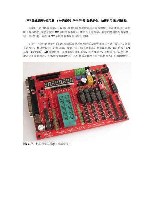
主体系统如图1所示,其配套书本教程《单片机快速入门》如图2所示。
图1 51单片机综合学习系统主机部分图片图2 51单片机综合学习系统配套书本教程——《单片机快速入门》上图是我们将要使用的51单片机综合学习系统硬件平台,如图1所示,本期实验我们用到了综合系统主机、板载的AT93C46芯片,综合系统其它功能模块原理与使用详见前几期《电子制作》杂志及后期连载教程介绍。
SPI总线简介SPI总线基本概念SPI ( Serial Peripheral Interface ———串行外设接口) 总线是Motorola公司推出的一种同步串行接口技术。
SPI总线系统是一种同步串行外设接口,允许MCU 与各种外围设备以串行方式进行通信、数据交换。
外围设备包括FLASHRAM、A/ D 转换器、网络控制器、MCU 等。
SPI,是一种高速的,全双工,同步的通信总线,并且在芯片的管脚上只占用四根线,节约了芯片的管脚,同时为PCB的布局上节省空间,提供方便,正是出于这种简单易用的特性,现在越来越多的芯片集成了这种通信协议。
其工作模式有两种:主模式和从模式。
SPI是一种允许一个主设备启动一个从设备的同步通讯的协议,从而完成数据的交换。
也就是SPI是一种规定好的通讯方式。
这种通信方式的优点是占用端口较少,一般4根就够基本通讯了(不算电源线)。
SPI协议详解
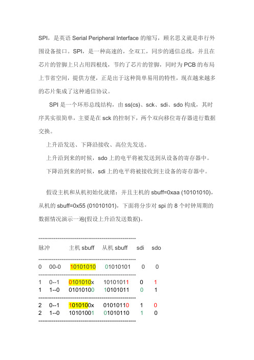
SPI,是英语Serial Peripheral Interface的缩写,顾名思义就是串行外围设备接口。
SPI,是一种高速的,全双工,同步的通信总线,并且在芯片的管脚上只占用四根线,节约了芯片的管脚,同时为PCB的布局上节省空间,提供方便,正是出于这种简单易用的特性,现在越来越多的芯片集成了这种通信协议。
SPI是一个环形总线结构,由ss(cs)、sck、sdi、sdo构成,其时序其实很简单,主要是在sck的控制下,两个双向移位寄存器进行数据交换。
上升沿发送、下降沿接收、高位先发送。
上升沿到来的时候,sdo上的电平将被发送到从设备的寄存器中。
下降沿到来的时候,sdi上的电平将被接收到主设备的寄存器中。
假设主机和从机初始化就绪:并且主机的sbuff=0xaa (10101010),从机的sbuff=0x55 (01010101),下面将分步对spi的8个时钟周期的数据情况演示一遍(假设上升沿发送数据)。
---------------------------------------------------脉冲主机sbuff 从机sbuff sdi sdo---------------------------------------------------0 00-0 10101010 01010101 0 0---------------------------------------------------1 0--1 0101010x 101010110 11 1--0 0101010010101011 0 1---------------------------------------------------2 0--1 1010100x 01010110 1 02 1--0 1010100101010110 10---------------------------------------------------3 0--1 0101001x 101011010 13 1--0 0101001010101101 0 1---------------------------------------------------4 0--1 1010010x 01011010 1 04 1--0 1010010101011010 10---------------------------------------------------5 0--1 0100101x 101101010 15 1--0 0100101010110101 0 1---------------------------------------------------6 0--1 1001010x 01101010 1 06 1--0 1001010101101010 10---------------------------------------------------7 0--1 0010101x 110101010 17 1--0 0010101011010101 0 1---------------------------------------------------8 0--1 0101010x 10101010 1 08 1--0 0101010110101010 10---------------------------------------------------这样就完成了两个寄存器8位的交换,上面的0--1表示上升沿、1--0表示下降沿,sdi、sdo相对于主机而言的。
SPI通信协议详解
串行外设接口SPI通信协议详解什么是SPI?SPI的英文全称为Serial Peripheral Interface,顾名思义为串行外设接口。
SPI是一种同步串行通信接口规范,主要应用于嵌入式系统中的短距离通信。
该接口由摩托罗拉在20世纪80年代中期开发,后发展成了行业规范。
SPI通信的4种工作模式SPI通信中有4种不同的操作模式,不同的从机设备可能在出厂时就被设置好了某种模式,并且无法更改。
但是SPI通信必须处于同一种模式下才能进行。
因此我们应该对自己手里的SPI主机设备进行模式的配置,也就是通过CPOL(时钟极性)和CPHA(时钟相位)来控制SPI主设备的通信模式,具体如下:时钟极性(CPOL)定义了SCLK时钟线空闲状态时的电平:1.CPOL=0,即SCLK=0,表示SCLK时钟信号线在空闲状态时的电平为低电平,因此有效状态为高电平。
2.CPOL=1,即SCLK=1,表示SCLK时钟信号线在空闲状态时的电平为高电平,因此有效状态为低电平。
时钟相位(CPHA)定义了数据位相对于时钟线的时序(即相位):1.CPHA=0,即表示输出(out)端在上一个时钟周期的后沿改变数据,而输入(in)端在时钟周期的前沿(或不久之后)捕获数据。
输出端保持数据有效直到当前时钟周期的尾部边缘。
对于第一个时钟周期来说,第一位的数据必须在时钟前沿之前出现在MOSI线上。
也就是一个CPHA=0的周期包括半个时钟空闲和半个时钟置位的周期。
2.CPHA=1,即表示输出(out)端在当前时钟周期的前沿改变数据,而输入(in)端在时钟周期的后沿(或不久之后)捕获数据。
输出端保持数据有效直到下一个时钟周期的前沿。
对于最后一个时钟周期来说,从机设备在片选信号消失之前保持MISO信号线有效。
也就是一个CHPA=1的周期包括半个时钟置位和半个时钟空闲的周期。
Note:此处的前沿和后沿的意思表示在每个周期中第一个出现的边沿和最后一个出现的边沿。
spi接口协议
spi接口协议SPI接口协议。
SPI(Serial Peripheral Interface)是一种同步串行数据接口标准,用于在数字集成电路之间进行通信。
SPI接口协议最初由Motorola公司开发,后来得到了广泛的应用和推广,成为了一种常见的通信协议。
SPI接口协议主要用于在嵌入式系统中连接微控制器和外围设备,如存储器芯片、传感器、显示器等。
SPI接口协议的特点之一是它是一种全双工通信协议,意味着数据可以同时在两个方向上传输。
它还采用了主从式的通信方式,一个主设备可以控制多个从设备,这使得SPI接口协议在多设备通信时表现出色。
此外,SPI接口协议的通信速度较快,可以达到几十MHz甚至上百MHz,适用于高速数据传输的场景。
SPI接口协议的硬件连接通常由四条线构成,时钟线(SCLK)、主设备输出从设备输入线(MOSI)、主设备输入从设备输出线(MISO)和片选线(SS)。
时钟线用于同步数据传输,主设备通过时钟线向从设备发送时钟信号,从而控制数据传输的速度。
MOSI和MISO分别用于主设备向从设备发送数据和从设备向主设备发送数据。
片选线用于选择需要进行通信的从设备,每个从设备都有一个对应的片选线。
在SPI接口协议中,数据的传输是以字节为单位进行的。
主设备通过向从设备发送数据来触发从设备的响应,从而进行数据交换。
SPI接口协议的通信过程可以分为四个阶段,片选、传输、接收和解选。
首先,主设备通过片选线选择需要进行通信的从设备;然后,在时钟的控制下,主设备向从设备发送数据,并同时接收从设备发送的数据;最后,主设备通过解选线将从设备解选,结束本次通信。
SPI接口协议的应用非常广泛,特别是在嵌入式系统中。
由于其高速、全双工和多设备通信的特点,SPI接口协议被广泛应用于存储器、传感器、显示器、通信模块等外围设备的连接。
在一些对通信速度要求较高的场景,SPI接口协议的优势尤为明显。
总的来说,SPI接口协议是一种简单而高效的通信协议,适用于在数字集成电路之间进行数据交换。
SPI时序图详解及SPI总线协议
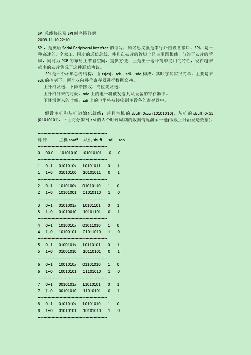
SPI总线协议及SPI时序图详解2009-11-1022:10SPI,是英语Serial Peripheral Interface的缩写,顾名思义就是串行外围设备接口。
SPI,是一种高速的,全双工,同步的通信总线,并且在芯片的管脚上只占用四根线,节约了芯片的管脚,同时为PCB的布局上节省空间,提供方便,正是出于这种简单易用的特性,现在越来越多的芯片集成了这种通信协议。
SPI是一个环形总线结构,由ss(cs)、sck、sdi、sdo构成,其时序其实很简单,主要是在sck的控制下,两个双向移位寄存器进行数据交换。
上升沿发送、下降沿接收、高位先发送。
上升沿到来的时候,sdo上的电平将被发送到从设备的寄存器中。
下降沿到来的时候,sdi上的电平将被接收到主设备的寄存器中。
假设主机和从机初始化就绪:并且主机的sbuff=0xaa(10101010),从机的sbuff=0x55 (01010101),下面将分步对spi的8个时钟周期的数据情况演示一遍(假设上升沿发送数据)。
---------------------------------------------------脉冲主机sbuff从机sbuff sdi sdo---------------------------------------------------000-0101010100101010100---------------------------------------------------10--10101010x101010110111--0010101001010101101---------------------------------------------------20--11010100x010*******21--0101010010101011010---------------------------------------------------30--10101001x101011010131--0010100101010110101---------------------------------------------------40--11010010x010*******41--0101001010101101010---------------------------------------------------50--10100101x101101010151--0010010101011010101---------------------------------------------------60--11001010x011010101061--0100101010110101010---------------------------------------------------70--10010101x110101010171--0001010101101010101---------------------------------------------------80--10101010x101010101081--0010101011010101010---------------------------------------------------这样就完成了两个寄存器8位的交换,上面的0--1表示上升沿、1--0表示下降沿,sdi、sdo 相对于主机而言的。
SPI通信协议详解(四)
SPI通信协议详解(四)1.SPI协议简介板卡内不同芯⽚间通讯最常⽤的三种串⾏协议:UART、I2C、SPI,之前写过串⼝协议及其FPGA实现,今天我们来介绍SPI协议,SPI是Serial Perripheral Interface的简称,是由Motorola公司推出的⼀种⾼速、全双⼯的总线协议。
与IIC类似,SPI也是采⽤主从⽅式⼯作,主机通常为FPGA、MCU或DSP等可编程控制器,从机通常为EPROM、Flash,AD/DA,⾳视频处理芯⽚等设备。
⼀般由SCLK、CS、MOSI,MISO四根线组成,有的地⽅可能是:SCK、SS、SDI、SDO等名称,都是⼀样的含义,当有多个从机存在时,通过CS来选择要控制的从机设备。
和标准SPI类似的协议,还有TI的SSP协议,区别主要在⽚选信号的时序上。
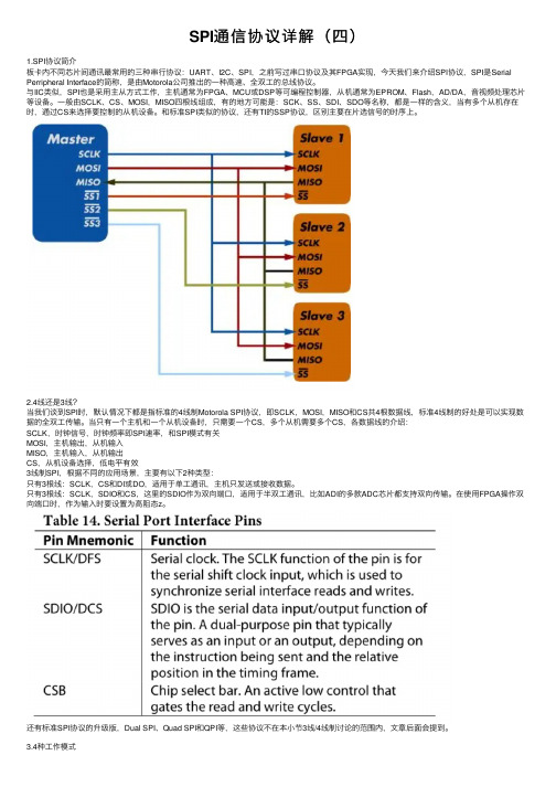
2.4线还是3线?当我们谈到SPI时,默认情况下都是指标准的4线制Motorola SPI协议,即SCLK,MOSI,MISO和CS共4根数据线,标准4线制的好处是可以实现数据的全双⼯传输。
当只有⼀个主机和⼀个从机设备时,只需要⼀个CS,多个从机需要多个CS,各数据线的介绍:SCLK,时钟信号,时钟频率即SPI速率,和SPI模式有关MOSI,主机输出,从机输⼊MISO,主机输⼊,从机输出CS,从机设备选择,低电平有效3线制SPI,根据不同的应⽤场景,主要有以下2种类型:只有3根线:SCLK,CS和DI或DO,适⽤于单⼯通讯,主机只发送或接收数据。
只有3根线:SCLK,SDIO和CS,这⾥的SDIO作为双向端⼝,适⽤于半双⼯通讯,⽐如ADI的多款ADC芯⽚都⽀持双向传输。
在使⽤FPGA操作双向端⼝时,作为输⼊时要设置为⾼阻态z。
还有标准SPI协议的升级版,Dual SPI、Quad SPI和QPI等,这些协议不在本⼩节3线/4线制讨论的范围内,⽂章后⾯会提到。
3.4种⼯作模式既然是进⾏数据传输,双⽅就要明确从机在什么时刻去采样主机发出的数据,主机在什么时刻去读取从机发来的数据。
SPI协议介绍
SPI协议介绍1、 SPI简介SPI,是英语Serial Peripheral interface的缩写,顾名思义就是串⾏外围设备接⼝。
是Motorola⾸先在其MC68HCXX系列处理器上定义的。
SPI接⼝主要应⽤在 EEPROM,FLASH,实时时钟,AD转换器,还有数字信号处理器和数字信号解码器之间。
SPI,是⼀种⾼速的,全双⼯,同步的通信总线,并且在芯⽚的管脚上只占⽤四根线,节约了芯⽚的管脚,同时为PCB的布局上节省空间,提供⽅便,正是出于这种简单易⽤的特性,现在越来越多的芯⽚集成了这种通信协议。
2、 SPI特点2.1采⽤主-从模式(Master-Slave) 的控制⽅式SPI 规定了两个 SPI 设备之间通信必须由主设备 (Master) 来控制次设备 (Slave). ⼀个 Master 设备可以通过提供 Clock 以及对 Slave 设备进⾏⽚选 (Slave Select) 来控制多个 Slave 设备, SPI 协议还规定 Slave 设备的 Clock 由 Master 设备通过 SCK 管脚提供给 Slave 设备, Slave 设备本⾝不能产⽣或控制 Clock, 没有 Clock 则 Slave 设备不能正常⼯作2.2采⽤同步⽅式(Synchronous)传输数据Master 设备会根据将要交换的数据来产⽣相应的时钟脉冲(Clock Pulse), 时钟脉冲组成了时钟信号(Clock Signal) , 时钟信号通过时钟极性(CPOL) 和时钟相位 (CPHA) 控制着两个 SPI 设备间何时数据交换以及何时对接收到的数据进⾏采样, 来保证数据在两个设备之间是同步传输的.2.3数据交换(Data Exchanges)SPI 设备间的数据传输之所以⼜被称为数据交换, 是因为 SPI 协议规定⼀个 SPI 设备不能在数据通信过程中仅仅只充当⼀个 "发送者(Transmitter)" 或者 "接收者(Receiver)". 在每个 Clock 周期内, SPI 设备都会发送并接收⼀个 bit ⼤⼩的数据, 相当于该设备有⼀个 bit ⼤⼩的数据被交换了. ⼀个 Slave 设备要想能够接收到 Master 发过来的控制信号, 必须在此之前能够被 Master 设备进⾏访问 (Access). 所以, Master 设备必须⾸先通过 SS/CS pin 对 Slave 设备进⾏⽚选, 把想要访问的 Slave 设备选上. 在数据传输的过程中, 每次接收到的数据必须在下⼀次数据传输之前被采样. 如果之前接收到的数据没有被读取, 那么这些已经接收完成的数据将有可能会被丢弃, 导致 SPI 物理模块最终失效. 因此, 在程序中⼀般都会在 SPI 传输完数据后, 去读取 SPI 设备⾥的数据, 即使这些数据(Dummy Data)在我们的程序⾥是⽆⽤的。
SPI总线规范

SPI总线规范SPI是英文Serial Peripheral Interface的缩写,中文意思是串行外围设备接口,SPI是Motorola公司推出的一种同步串行通讯方式,是一种三线同步总线,因其硬件功能很强,与SPI有关的软件就相当简单,使CPU有更多的时间处理其他事务。
SPI概述SPI:高速同步串行口。
3~4线接口,收发独立、可同步进行.SPI,是英语Serial Peripheral interface的缩写,顾名思义就是串行外围设备接口。
是Motorola首先在其MC68HCX X系列处理器上定义的。
SPI接口主要应用在EEPROM,FLASH,实时时钟,AD转换器,还有数字信号处理器和数字信号解码器之间。
SPI,是一种高速的,全双工,同步的通信总线,并且在芯片的管脚上只占用四根线,节约了芯片的管脚,同时为PCB的布局上节省空间,提供方便,正是出于这种简单易用的特性,现在越来越多的芯片集成了这种通信协议,比如AT91RM9200.SPI总线系统是一种同步串行外设接口,它可以使MCU与各种外围设备以串行方式进行通信以交换信息。
外围设置FLASH RAM、网络控制器、LCD显示驱动器、A/D转换器和MCU等。
SPI总线系统可直接与各个厂家生产的多种标准外围器件直接接口,该接口一般使用4条线:串行时钟线(SCK)、主机输入/从机输出数据线MISO、主机输出/从机输入数据线MOSI和低电平有效的从机选择线SS(有的SPI接口芯片带有中断信号线INT或INT、有的SPI接口芯片没有主机输出/从机输入数据线MOSI)。
SPI的通信原理很简单,它以主从方式工作,这种模式通常有一个主设备和一个或多个从设备,需要至少4根线,事实上3根也可以(单向传输时)。
也是所有基于SPI的设备共有的,它们是SDI(数据输入),SDO(数据输出),SCK(时钟),CS(片选)。
(1)SDO –主设备数据输出,从设备数据输入(2)SDI –主设备数据输入,从设备数据输出(3)SCLK –时钟信号,由主设备产生(4)CS –从设备使能信号,由主设备控制其中CS是控制芯片是否被选中的,也就是说只有片选信号为预先规定的使能信号时(高电位或低电位),对此芯片的操作才有效。
SPI总线协议

SPI总线协议同步外设接口(SPI)是由摩托罗拉公司开发的全双工同步串行总线,该总线大量用在与EEPROM、ADC、FRAM和显示驱动器之类的慢速外设器件通信。
SPI(Serial Peripheral Interface)是一种串行同步通讯协议,由一个主设备和一个或多个从设备组成,主设备启动一个与从设备的同步通讯,从而完成数据的交换。
SPI 接口由SDI(串行数据输入),SDO(串行数据输出),SCK(串行移位时钟),CS(从使能信号)四种信号构成,CS 决定了唯一的与主设备通信的从设备,如没有CS 信号,则只能存在一个从设备,主设备通过产生移位时钟来发起通讯。
通讯时,数据由SDO 输出,SDI 输入,数据在时钟的上升或下降沿由SDO 输出,在紧接着的下降或上升沿由SDI 读入,这样经过8/16 次时钟的改变,完成8/16 位数据的传输。
SPI通信该总线通信基于主-从配置。
它有以下4个信号:MOSI:主出/从入MISO:主入/从出SCK:串行时钟SS:从属选择芯片上“从属选择”(slave-select)的引脚数决定了可连到总线上的器件数量。
在SPI传输中,数据是同步进行发送和接收的。
数据传输的时钟基于来自主处理器的时钟脉冲,摩托罗拉没有定义任何通用SPI的时钟规范。
然而,最常用的时钟设置基于时钟极性(CPOL)和时钟相位(CPHA)两个参数,CPOL定义SPI串行时钟的活动状态,而CPHA定义相对于SO-数据位的时钟相位。
CPOL和CPHA的设置决定了数据取样的时钟沿。
数据方向和通信速度SPI传输串行数据时首先传输最高位。
波特率可以高达5Mbps,具体速度大小取决于SPI 硬件。
例如,Xicor公司的SPI串行器件传输速度能达到5MHz。
SPI总线接口及时序SPI总线包括1根串行同步时钟信号线以及2根数据线。
SPI模块为了和外设进行数据交换,根据外设工作要求,其输出串行同步时钟极性和相位可以进行配置,时钟极性(CPOL)对传输协议没有重大的影响。
SPI总线协议介绍(易懂)

SPI总线协议介绍(易懂)目录CONTENTS•SPI总线协议产生背景•SPI总线协议内容介绍•SPI总线协议总结一、SPI总线协议背景12 SPI是由摩托罗拉(Motorola)公司于1979年开发的全双工同步串行总线,是微处理控制单元(MCU)和外围设备之间进行通信的同步串行端口。
主要应用在EEPROM、Flash、实时时钟(RTC)、数模转换器(ADC)、网络控制器、MCU、数字信号处理器(DSP)以及数字信号解码器之间。
SPI,全称Serial Peripheral Interface,中文意思是串行外部设备接口,是一种全双工、高速、同步的通信总线。
SPI 总线器件可直接与各个厂家生产的多种标准外围器件直接接口,一般使用4 条线:串行时钟线SCLK、主机输入/从机输出数据线MISO、主机输出/从机输入数据线MOSI 和低电平有效的从机选择线CS3SPI总线术语及定义,如表(1)所示:表(1) SPI总线术语及定义二、SPI总线协议内容1<1>.SPI总线采用主从模式架构,支持多从设备应用,一般只支持单主设备;<2>.当主设备想要和某从设备进行通信时候,主设备需要先向对应从设备的片选线(CS)山发送使能信号(高电平或者低电平,按从设备而定),表示选中该从设备;<3>.时钟由主设备控制,数据在时钟脉冲下按位传输,高位在前;<4>.目前应用中的数据速率可达几Mbps。
2SPI设备之间采用全双工模式通信,是一个主机和一个或者多个从机的主从模式。
主机负责初始化帧,这个数据传输帧可以用于读与写两种操作,片选线可以从多个从机选择一个来响应主机的请求。
如图(1)、图(2)、图(3)和图(4)所示图(1)SPI连接类型首先Master产生时钟,时钟频率小于或等于Slave支持的最大频率;随后Master通过产生时钟信号(SCLK)来控制数据传输,并通过将特定Slave的芯片选择(CS)线拉低来进行通信。
SPI总线协议及SPI时序图详解
SPI总线协议及SPI时序图详解SPI,是英语Serial Peripheral Interface的缩写,顾名思义就是串行外围设备接口。
SPI,是一种高速的,全双工,同步的通信总线,并且在芯片的管脚上只占用四根线,节约了芯片的管脚,同时为PCB的布局上节省空间,提供方便,正是出于这种简单易用的特性,现在越来越多的芯片集成了这种通信协议。
SPI是一个环形总线结构,由ss(cs)、sck、sdi、sdo构成,其时序其实很简单,主要是在sck的控制下,两个双向移位寄存器进行数据交换。
上升沿发送、下降沿接收、高位先发送。
上升沿到来的时候,sdo上的电平将被发送到从设备的寄存器中。
下降沿到来的时候,sdi上的电平将被接收到主设备的寄存器中。
假设主机和从机初始化就绪:并且主机的sbuff=0xaa (10101010),从机的sbuff=0x55 (01010101),下面将分步对spi的8个时钟周期的数据情况演示一遍(假设上升沿发送数据)。
---------------------------------------------------脉冲主机sbuff 从机sbuff sdi sdo---------------------------------------------------0 00-0 10101010 01010101 0 0---------------------------------------------------1 0--1 0101010x 10101011 0 11 1--0 01010100 10101011 0 1---------------------------------------------------2 0--1 1010100x 01010110 1 02 1--0 10101001 01010110 1 0---------------------------------------------------3 0--1 0101001x 10101101 0 13 1--0 01010010 10101101 0 1---------------------------------------------------4 0--1 1010010x 01011010 1 04 1--0 10100101 01011010 1 0---------------------------------------------------5 0--1 0100101x 10110101 0 15 1--0 01001010 10110101 0 1---------------------------------------------------6 0--1 1001010x 01101010 1 06 1--0 10010101 01101010 1 0---------------------------------------------------7 0--1 0010101x 11010101 0 17 1--0 00101010 11010101 0 1---------------------------------------------------8 0--1 0101010x 10101010 1 08 1--0 01010101 10101010 1 0---------------------------------------------------这样就完成了两个寄存器8位的交换,上面的0--1表示上升沿、1--0表示下降沿,sdi、sdo相对于主机而言的。
SPI文档(Moto)
8SECTION 8 SYNCHRONOUS SERIAL PERIPHERAL INTERFACE The serial peripheral interface (SPI) is one of two independent serial communications subsystems included on the MC68HC11A8. As the name implies, the SPI is primarily used to allow the microcontroller unit (MCU) to communicate with peripheral devices.The SPI is also capable of interprocessor communications in a multiple-master sys-tem. Peripheral devices are as simple as an ordinary transistor-transistor logic (TTL)shift register or as complex as a complete subsystem, such as a liquid crystal diode (LCD) display driver or an analog-to-digital (A/D) converter subsystem. The SPI sys-tem is flexible enough to interface directly with numerous standard product peripherals from several manufacturers. The system can be configured as a master or a slave de-vice. Data rates as high as 1 Mbit per second are accommodated when the system is configured as a master; rates as high as 2 Mbits per second are accommodated when the system is operated as a slave.Clock control logic allows a selection of clock polarity and a choice of two fundamen-tally different clocking protocols to accommodate most available synchronous serial peripheral devices. When the SPI is configured as a master, software selects one of four different bit rates for the serial clock.Error-detection logic is included to support interprocessor communications. A write-collision detector indicates when an attempt is made to write data to the serial shift reg-ister while a transfer is in progress. A multiple-master mode-fault detector automatical-ly disables SPI output drivers if more than one MCU simultaneously attempts to become bus master.The I/O pin control logic on the MC68HC11A8 is more flexible than that of other Mo-torola MCUs. This added I/O pin control allows the MC68HC11A8 to implement sys-tems with a single, bidirectional data line or other unusual synchronous serial configurations.8.1 SPI Transfer FormatsDuring an SPI transfer, data is simultaneously transmitted (shifted out serially) and re-ceived (shifted in serially). A serial clock line synchronizes shifting and sampling of the information on the two serial data lines. A slave select line allows individual selection of a slave SPI device; slave devices that are not selected do not interfere with SPI bus activities. On a master SPI device, the slave select line can optionally be used to indi-cate a multiple-master bus contention.8.1.1 SPI Clock Phase and Polarity ControlsSoftware can select any of four combinations of serial clock (SCK) phase and polarity using two bits in the SPI control register (SPCR). The clock polarity is specified by the CPOL control bit, which selects an active high or active low clock and has no signifi-cant effect on the transfer format. The clock phase (CPHA) control bit selects one of8two fundamentally different transfer formats. The clock phase and polarity should be identical for the master SPI device and the communicating slave device. In some cas-es, the phase and polarity are changed between transfers to allow a master device to communicate with peripheral slaves having different requirements. The flexibility of the SPI system on the MC68HC11A8 allows direct interface to almost any existing syn-chronous serial peripheral.8.1.2 CPHA Equals Zero Transfer FormatFigure 8-1 is a timing diagram of an SPI transfer where CPHA is zero. Two waveforms are shown for SCK: one for CPOL equals zero and another for CPOL equals one. The diagram may be interpreted as a master or slave timing diagram since the SCK, mas-ter in/slave out (MISO), and master out/slave in (MOSI) pins are directly connected be-tween the master and the slave. The MISO signal is the output from the slave, and the MOSI signal is the output from the master. The SS line is the slave select input to the slave; the SS pin of the master is not shown but is assumed to be inactive. The SS pin of the master must be high or must be reconfigured as a general-purpose output not affecting the SPI. This timing diagram functionally depicts how a transfer takes place;it should not be used as a replacement for data-sheet parametric information.Figure 8-1 CPHA Equals Zero SPI Transfer Format8.1.3 CPHA Equals One Transfer FormatFigure 8-2 is a timing diagram of an SPI transfer where CPHA is one. Two waveforms are shown for SCK: one for CPOL equals zero and another for CPOL equals one. The diagram may be interpreted as a master or slave timing diagram since the SCK, MISO, and MOSI pins are directly connected between the master and the slave. The MISO signal is the output from the slave, and the MOSI signal is the output from the master.The SS line is the slave select input to the slave; the SS pin of the master is not shown but is assumed to be inactive. The SS pin of the master must be high or must be re-configured as a general-purpose output not affecting the SPI. This timing diagram functionally illustrates how a transfer takes place; it should not be used as a replace-ment for data-sheet parametric information.MSB654321LSB*654321Not defined but normally MSB of character just received.23456781MSBMISO(FROM SLAVE)MOSI(FROM MASTER)SCK (CPOL=1)SCK (CPOL=0)SCK CYCLE #(FOR REFERENCE)SS (TO SLAVE)LSB*8Figure 8-2 CPHA Equals One SPI Transfer FormatWhen CPHA equals zero, the SS line must be negated and reasserted between each successive serial byte. Also, if the slave writes data to the SPI data register (SPDR)while SS is active low, a write-collision error results. When CPHA equals one, the SS line may remain active low between successive transfers (can be tied low at all times). This format is sometimes preferred in systems having a single fixed master and a single slave driving the MISO data line.8.2 SPI Block DiagramFigure 8-3is a block diagram of the SPI subsystem. When an SPI transfer occurs, an 8-bit character is shifted out one data pin while a different 8-bit character is simulta-neously shifted in a second data pin. Another way to view this transfer is that an 8-bit shift register in the master and another 8-bit shift register in the slave are connected as a circular 16-bit shift register. When a transfer occurs, this distributed shift register is shifted eight bit positions; thus, the characters in the master and slave are effectively exchanged.The central element in the SPI system is the block containing the shift register and the read data buffer. The system is single buffered in the transmit direction and double buffered in the receive direction. This fact means new data for transmission cannot be written to the shifter until the previous transaction is complete; however, received data is transferred into a parallel read data buffer so the shifter is free to accept a second serial character. As long as the first character is read out of the read data buffer before the next serial character is ready to be transferred, no overrun condition will occur. A single MCU register address is used for reading data from the read data buffer and for writing data to the shifter.Not defined but normally LSB of previously transmitted character.654321LSB654321LSB23456781MSB MISO (FROM SLAVE)MOSI (FROM MASTER)SCK (CPOL=1)SCK (CPOL=0)SCK CYCLE #(FOR REFERENCE)SS (TO SLAVE)MSB ∗∗8Figure 8-3 SPI System Block Diagram8.3 SPI Pin SignalsThere are four I/O pin signals associated with SPI transfers: the SCK, the MISO data line, the MOSI data line, and the active low SS pin. When the SPI system is disabled,the four pins are configured for general-purpose I/O, and the primary direction of data is controlled by a data direction control bit corresponding to each I/O pin. When the SPI system is enabled, the data direction control bits still influence the direction of data at the pins. Detailed logic for these pins is included in SECTION 7 PARALLEL INPUT/OUTPUT. The following rules will answer the most common questions. When the SPI system is on and expects a pin to be an input, the pin will be configured as an input regardless of the state of its data direction control bit. When the SPI system is on and expects a pin to be an output, the pin will be configured as an output only if its data direction control bit is set to one. When the SPI is configured as a master, the PD5/SS pin is a special case.INTERNAL DATA BUSSPI INTERRUPTREQUEST8 NOTESPI transfers will not occur unless the outputs are enabled by settingthe corresponding DDRD bits. SPI outputs are disabled (high imped-ance) unless their corresponding DDRD bits are set to one. SPIinputs are configured as high-impedance inputs even if their corre-sponding DDRD bits are set to one.The SCK pin is an output when the SPI is configured as a master and an input when the SPI is configured as a slave. When the SPI is configured as a master, the SCK signal is derived from the internal MCU bus clock. When the master initiates a transfer,eight clock cycles are automatically generated on the SCK pin. When the SPI is con-figured as a slave, the SCK pin is an input, and the clock signal from the master syn-chronizes the data transfer between the master and slave devices. Slave devices ignore the SCK signal unless the slave select pin is active low. In both the master and slave SPI devices, data is shifted on one edge of the SCK signal and is sampled on the opposite edge where data is stable. Edge polarity is determined by the SPI transfer protocol.The MISO and MOSI data pins are used for transmitting and receiving serial data.When the SPI is configured as a master, MISO is the master data input line, and MOSI is the master data output line. When the SPI is configured as a slave, these pins re-verse roles. In a multiple-master system, all SCK pins are tied together, all MOSI pins are tied together, and all MISO pins are tied together. A single SPI device is configured as a master; all other SPI devices on the SPI bus are configured as slaves. The single master drives data out its SCK and MOSI pins to the SCK and MOSI pins of the slaves.One selected slave device optionally drives data out its MISO pin to the MISO master pin. The automatic control of the direction of these pins makes reconfiguration through external logic unnecessary when a new device becomes the master. The SS pin behaves differently on master and slave devices. On a slave device, this pin is used to enable the SPI slave for a transfer. If the SS pin of a slave is inactive (high), the device ignores SCK clocks and keeps the MISO output pin in the high-im-pedance state. On a master device, the SS pin can optionally serve as an error-detec-tion input for the SPI or as a general-purpose output not affecting the SPI. The choice is based on the corresponding data direction control bit (DDRD5). When DDRD5 is logic one and the SPI is configured as a master, the PD5/SS pin acts as a general-purpose output that is independent of SPI activities. When the DDRD5 bit is logic zero and the SPI system is configured as a master, the SS pin acts as an error-detection input, which should remain high. If the SS pin goes low while the SPI is a master and is using the SS pin as an error-detection input, it indicates that some other device on the SPI bus is attempting to be a master. This attempt causes the master device sens-ing the error to immediately exit the SPI bus to avoid potentially damaging driver con-tentions. This detection is called a mode fault and is discussed in 8.5.1 SPI Mode-Fault Error.The port D I/O pins, including the four SPI pins, can be configured to behave as open-drain drivers. The port D wired-OR mode (DWOM) control bit is used to enable this option. An external pull-up resistor is required on each port D output pin while this op-tion is selected. In multiple-master systems, this option provides extra protection8against CMOS latchup because, even if more than one SPI device tries to simulta-neously drive the same bus line, there will be no destructive contention. Other unusual SPI system configurations also benefit from this option (e.g., when MISO and MOSI are tied together to form a single, bidirectional data line).8.4 SPI RegistersThe SPI control register (SPCR), SPI status register (SPSR), and SPDR are software-accessible registers used to configure and operate the SPI system. Because the portD data direction control register (DDRD) influences SPI activities, it will be discussedbriefly. Detailed logic diagrams of the port D pins can be found in SECTION 7 PAR-ALLEL INPUT/OUTPUT.8.4.1 Port D Data Direction Control Register (DDRD)This register, which may be read or written at any time, is used to control the primary direction of port D pins. Bits 5, 4, 3, and 2 of port D are used by the SPI system when the SPI enable (SPE) control bit is one. The serial communications interface (SCI) sys-tem uses the other two bits of port D when the SCI receiver and transmitter are en-abled. This description of DDRD is only intended to cover material related to the SPI system.DDRD5 — Data Direction Control for Port D Bit 5 (SS)When the SPI system is enabled as a slave (SPE = 1; MSTR = 0), the PD5/SS pin is the slave select input, regardless of the value of DDRD5. When the SPI system is en-abled as a master (SPE = 1; MSTR = 1), the function of the PD5/SS pin depends on the value in DDRD5.0 = The SS pin is used as an input to detect mode-fault errors. A low on this pinindicates that some other device in a multiple-master system has become amaster and is trying to select this MCU as a slave. To prevent harmful conten-tions between output drivers, a mode fault is generated, which causes the de-vice sensing the fault to immediately change all of its SPI pins to highimpedance. Additional information on mode faults is given in 8.5.1 SPI Mode-Fault Error.1 = The PD5/SS pin acts as a general-purpose output not affected by the SPI sys-tem. Because the mode-fault detection logic in the SPI is disabled, changingthis PD5 output pin to zero does not affect the SPI system.DDRD4 — Data Direction Control for Port D Bit 4 (SCK)When the SPI system is enabled as a slave, the PD4/SCK pin acts as the SPI serial clock input, regardless of the state of DDRD4. When the SPI system is enabled as a master, the DDRD4 bit must be set to one to enable the SCK output.DDRD — Port D Data Direction Register$1009 BIT 7654321BIT 0——DDRD5DDRD4DDRD3DDRD2DDRD1DDRD0RESET:00000000REFER-ENCE:——TS SCK MOSI MISO TxD RxD8DDRD3 — Data Direction Control for Port D Bit 3 (MOSI)When the SPI system is enabled as a slave, the PD3/MOSI pin acts as the slave serial data input, regardless of the state of DDRD3.When the SPI system is enabled as a master, the DDRD3 bit must be set to one to enable the master serial data output. If a master device wants to initiate an SPI transfer to receive a byte of data from a slave without transmitting a byte, it might purposely leave the MOSI output disabled. SPI systems that tie MOSI and MISO together to form a single bidirectional data line also need to selectively disable the MOSI output. DDRD2 — Data Direction Control for Port D Bit 2 (MISO)When the SPI system is enabled as a slave, the DDRD2 bit must be set to one to en-able the slave serial data output. A master SPI device can simultaneously broadcast a message to several slaves as long as no more than one of the slaves tries to drive the MISO line. SPI systems that tie MOSI and MISO together to form a single bidirec-tional data line also need to selectively disable the MISO output.When the SPI system is enabled as a master, the PD2/MISO pin acts as the master serial data input, regardless of the state of DDRD2.8.4.2 SPI Control Register (SPCR)This register, which may be read or written at any time, is used to configure the SPI system. The DDRD register must also be properly configured before SPI transfers can occur.SPIE — SPI Interrupt Enable0 = SPI interrupts are disabled. Polling is used to sense the SPIF and MODF flags. 1 = SPI interrupt is requested if SPIF or MODF set (provided I bit in condition coderegister (CCR) is zero).SPE — SPI System Enable0 = SPI system is off.1 = SPI system is on.DWOM — Port D Wired-OR Mode Select0 = Port D outputs are push-pull.1 = P-channel pull-ups on all six port D output drivers are disabled so port D outputsact as open-drain drivers.MSTR — Master/Slave Mode Select0 = SPI is configured as a slave.1 = SPI is configured as a master.SPCR — SPI Control Register $1028BIT 7654321BIT 0SPIE SPE DWOM MSTR CPOL CPHA SPR1SPR0RESET:000001U U8CPOL — Clock Polarity Select0 = Active high clocks selected; SCK idles low.1 = Active low clocks selected; SCK idles high.CPHA — Clock Phase SelectThis control bit selects one of two fundamentally different transfer formats (see 8.1 SPI Transfer Formats).SPR1, SPR0 — SPI Bit Rate SelectThe following table shows the relationship between the SPR1 and SPR0 control bits and the bit rate for transfers when the SPI is operating as a master. When the SPI is operating as a slave, the serial clock is input from the master; therefore, the SPR1 and SPR0 control bits have no meaning.8.4.3 SPI Status Register (SPSR)This read-only register contains status flags indicating the completion of an SPI trans-fer and the occurrence of certain SPI system errors. The flags are automatically set by the occurrence of the corresponding SPI events; the flags are cleared by automatic software sequences.SPIF — SPI Transfer Complete FlagThis flag is automatically set to one at the end of an SPI transfer. SPIF is automatically cleared by reading the SPSR with SPIF set, followed by an access of the SPDR. The definition of end of a transfer varies with master versus slave and the transfer format specified by CPHA. This subject is discussed in 8.6 Beginning and Ending SPI Transfers.WCOL — Write Collision Error FlagThis flag is automatically set if the SPDR is written while a transfer is in progress.WCOL is automatically cleared by reading the SPSR with WCOL set, followed by an access of the SPDR. The details of when a transfer technically begins and ends de-pend on the configuration of the SPI system, which is discussed in 8.6 Beginning and Ending SPI Transfers.Bit 5 — Not implemented; always reads zero.SPR1SPR0 E ClockDivided By00201410161132SPSR — SPI Status Register$1029 BIT 7654321BIT 0SPIF WCOL—MODF————RESET:8MODF — Mode-Fault Error Flag This flag is set if the SS signal goes to active low while the SPI is configured as a mas-ter (MSTR = 1). MODF is automatically cleared by reading the SPSR with MODF set,followed by a write to the SPCR. Because the mode-fault mechanism is intended to prevent damage due to conflicts between output drivers, it takes effect immediately,regardless of the SPI system configuration at the time of the fault. The MSTR control bit in the SPCR and all four DDRD control bits associated with the SPI are cleared,and an interrupt is generated subject to masking by the SPIE control bit and the I bit in the CCR. Mode-fault errors are discussed in greater detail in the following para-graphs.Bits [3:0] — Not implemented; always read zero.8.5 SPI System ErrorsTwo system errors can be detected by the SPI system in the MC68HC11A8. The first type error arises in a multiple-master system when more than one SPI device simulta-neously tries to be a master. This error is called a mode fault. The second type error,a write collision, indicates that an attempt has been made to write data to the SPDR while a transfer was in progress.8.5.1 SPI Mode-Fault ErrorWhen the SPI system is configured as a master and the SS input line goes to active low, a mode-fault error has occurred. Only an SPI master can experience a mode-fault error, caused when a second SPI device becomes a master and selects this device as if it were a slave. In cases where more than one device is concurrently configured as a master, there is a chance of contention between two pin drivers. For push-pull CMOS drivers, this contention can cause catastrophic latchup. When this type error is detect-ed, the following actions are taken immediately:1.The DDRD bits corresponding to the four SPI-related I/O pins are forced to zeroto disable all SPI output drivers.2.The MSTR control bit is forced to zero to reconfigure the SPI as a slave.3.The SPE control bit is forced to zero to disable the SPI system.4.The MODF status flag is set, and an SPI interrupt is generated subject to mask-ing by the SPIE bit and the I bit in the CCR.After software has corrected the problems that led to the mode fault, MODF is cleared and the system is returned to normal operation. The MODF flag is automatically cleared by reading SPSR while MODF is set, followed by a write to the SPDR. The DDRD must also be restored before SPI transfers can resume.In some cases, the mode-fault mechanism does not fully protect multiple-master sys-tems from driver contention. For example, suppose a second device becomes a mas-ter but does not immediately drive the SS pin of this master low. Perhaps a system fault selects two slave devices, and these slave devices try to simultaneously drive the MISO line. Both these cases result in output driver contentions, but neither causes a mode-fault error. Too many system configurations are possible to discuss all the pos-sibilities, but some suggestions will help the system designer find practical ways to prevent problems.8Under normal conditions, a moderate resistance, (i.e., 1 to 10K ohms) in series with an SPI pin does not adversely affect SPI transfer operations. If a driver contention oc-curs, this series resistance will protect the drivers against latchup. Another way to pro-tect against latchup would be to employ the DWOM option, which transforms the SPI output drivers into open-drain-type drivers. When the DWOM option is selected, it af-fects all six port D pins; therefore, pull-up resistors are needed on the PD0 and PD1 pins if they are being used as outputs. Both of these suggestions affect the maximum usable data rate, depending on the loading capacitance on the SPI lines.8.5.2 SPI Write-Collision ErrorsA write collision occurs if the SPDR is written while a transfer is in progress. Since theSPDR is not double buffered in the transmit direction, writes to SPDR cause data to be written directly into the SPI shift register. Because this write corrupts any transfer in progress, a write-collision error is generated. The transfer continues undisturbed, and the write data that caused the error is not written to the shifter.A write collision is normally a slave error because a slave has no control over when amaster will initiate a transfer. A master knows when a transfer is in progress; thus, there is no excuse for a master to generate a write-collision error, although the SPI log-ic can detect write collisions in a master as well as in a slave.The details of what constitutes a transfer in progress depend on the SPI configuration.For a master, a transfer starts when data is written to SPDR and ends when SPIF is set. For a slave with CPHA equals zero, a transfer starts when SS goes low and ends when SS returns high. In this instance, SPIF is set at the middle of the eighth SCK cy-cle when data is transferred from the shifter to the parallel data register, but the trans-fer is still in progress until SS goes high. For a slave with CPHA equals one, a transfer starts when the SCK line goes to its active level, which is the edge at the beginning of the first SCK cycle. The transfer ends in a slave in which CPHA equals one when SPIF is set.8.6 Beginning and Ending SPI TransfersThe two basic SPI transfer formats are described in 8.1 SPI Transfer Formats. A transfer includes the eight SCK cycles plus an initiation period at the beginning and ending period of the transfer. The details of the beginning and ending periods depend on the CPHA format selected and whether the SPI is configured as a master or a slave. The initiation delay period is also affected by the SPI clock rate selection when the SPI is configured as a master.It may be useful to refer to the transfer format illustrated in Figure 8-1 and Figure 8-2 to understand how the beginning and ending details fit into a complete transfer oper-ation.8.6.1 Transfer Beginning Period (Initiation Delay)All SPI transfers are started and controlled by a master SPI device. As a slave, the MC68HC11A8 considers a transfer to begin with the first SCK edge or the falling edge of SS, depending on the CPHA format selected. When CPHA equals zero, the fallingedge of SS indicates the beginning of a transfer. When CPHA equals one, the firstedge on the SCK indicates the start of the transfer. In either CPHA format, a transfercan be aborted by taking the SS line high, which causes the SPI slave logic and bit counters to be reset. The SCK rate selected has no effect on slave operations sincethe clock from the master is controlling transfers.When the SPI is configured as a master, transfers are started by a software write tothe SPDR. CPHA has no effect on the delay to the start of the transfer, but it does af-fect the initial state of the SCK signal. When CPHA equals zero, the SCK signal re-mains inactive for the first half of the first SCK cycle. When CPHA equals one, the firstSCK cycle begins with an edge on the SCK line from its inactive to its active level. TheSPI clock rate (selected by SPR[1:0]) affects the delay from the write to SPDR and thestart of the SPI transfer (see Figure 8-4). The internal SPI clock in the master is a free-running derivative of the internal MCU clock (PH2). SCK edges occur a small propa-gation delay after the rising edge of PH2. The rising edge of PH2 occurs at the middleof the E-clock low period. Since the SPI clock is free-running, there is an uncertaintyabout where the write to SPDR will occur relative to the slower SCK. This uncertainty8causes the variation in the initiation delay shown in Figure 8-4.8 Figure 8-4 Delay from Write SPDR to Transfer Start (Master)8.6.2 Transfer Ending PeriodAn SPI transfer is technically complete when the SPIF flag is set, but, depending on the configuration of the SPI system, there may be additional tasks. Because the SPI bit rate does not affect timing of the ending period, only the fastest rate will be consid-ered in discussions of the ending period.When the SPI is configured as a master, SPIF is set at the end of the eighth SCK cycle.When CPHA equals one, SCK is inactive for the last half of the eighth SCK cycle. Fig-ure 8-5shows the transfer ending period for a master. The SCK waveforms in this fig-ure show only the CPOL equals zero case, since clock polarity does not affect timingof the ending period. MAXMAX MAXMAXS C K =E ÷32S C K =E ÷16S C K =E ÷4S C K =E ÷28Figure 8-5 Transfer Ending for an SPI MasterWhen the SPI is operating as a slave, the ending period is different because the SCK line can be asynchronous to the MCU clocks of the slave and because the slave does not have access to as much information about SCK cycles as the master. For exam-ple, when CPHA equals one, where the last SCK edge occurs in the middle of the eighth SCK cycle, the slave has no way of knowing when the end of the last SCK cycle is. For these reasons, the slave considers the transfer complete after the last bit of se-rial data has been sampled, which corresponds to the middle of the eighth SCK cycle.A synchronization delay is required so the setting of the SPIF flag is properly posi-tioned relative to the internal PH2 clock of the slave. Figure 8-6 shows the ending pe-riod for a slave. The SCK waveforms in this figure show only the CPOL equals zerocase, since clock polarity does not affect timing of the ending period.SCK CYCLE #SCK (CPHA=0)SCK (CPHA=1)EARLIEST POSSIBLE STACKING DUE TO SPIF INTERRUPT (NO OTHER INTERRUPT PENDING)ER/W。
SPI通信协议(SPI总线)学习.doc
SPI通信协议(SPI总线)学习1、什么是SPI?SPI是串行外设接口(Serial Peripheral Interface)的缩写。
是Motorola 公司推出的一种同步串行接口技术,是一种高速的,全双工,同步的通信总线。
2、SPI优点支持全双工通信通信简单数据传输速率块3、缺点没有指定的流控制,没有应答机制确认是否接收到数据,所以跟IIC 总线协议比较在数据可靠性上有一定的缺陷。
4、特点1):高速、同步、全双工、非差分、总线式2):主从机通信模式5、协议通信时序详解1):SPI的通信原理很简单,它以主从方式工作,这种模式通常有一个主设备和一个或多个从设备,需要至少4根线,事实上3根也可以(单向传输时)。
也是所有基于SPI的设备共有的,它们是SDI(数据输入)、SDO(数据输出)、SCLK(时钟)、CS(片选)。
(1)SDO/MOSI –主设备数据输出,从设备数据输入;(2)SDI/MISO –主设备数据输入,从设备数据输出;(3)SCLK –时钟信号,由主设备产生;(4)CS/SS –从设备使能信号,由主设备控制。
当有多个从设备的时候,因为每个从设备上都有一个片选引脚接入到主设备机中,当我们的主设备和某个从设备通信时将需要将从设备对应的片选引脚电平拉低或者是拉高。
2):需要说明的是,我们SPI通信有4种不同的模式,不同的从设备可能在出厂是就是配置为某种模式,这是不能改变的;但我们的通信双方必须是工作在同一模式下,所以我们可以对我们的主设备的SPI模式进行配置,通过CPOL(时钟极性)和CPHA(时钟相位)来控制我们主设备的通信模式,具体如下:Mode0:CPOL=0,CPHA=0Mode1:CPOL=0,CPHA=1Mode2:CPOL=1,CPHA=0Mode3:CPOL=1,CPHA=1时钟极性CPOL是用来配置SCLK的电平出于哪种状态时是空闲态或者有效态,时钟相位CPHA是用来配置数据采样是在第几个边沿:CPOL=0,表示当SCLK=0时处于空闲态,所以有效状态就是SCLK 处于高电平时CPOL=1,表示当SCLK=1时处于空闲态,所以有效状态就是SCLK 处于低电平时CPHA=0,表示数据采样是在第1个边沿,数据发送在第2个边沿CPHA=1,表示数据采样是在第2个边沿,数据发送在第1个边沿例如:CPOL=0,CPHA=0:此时空闲态时,SCLK处于低电平,数据采样是在第1个边沿,也就是SCLK由低电平到高电平的跳变,所以数据采样是在上升沿,数据发送是在下降沿。
SPI总线通俗易懂讲解
SPI总线通俗易懂讲解SPI总线MOTOROLA公司的SPI总线的基本信号线为3根传输线,即SI、SO、SCK。
传输的速率由时钟信号SCK决定,SI为数据输入、SO为数据输出。
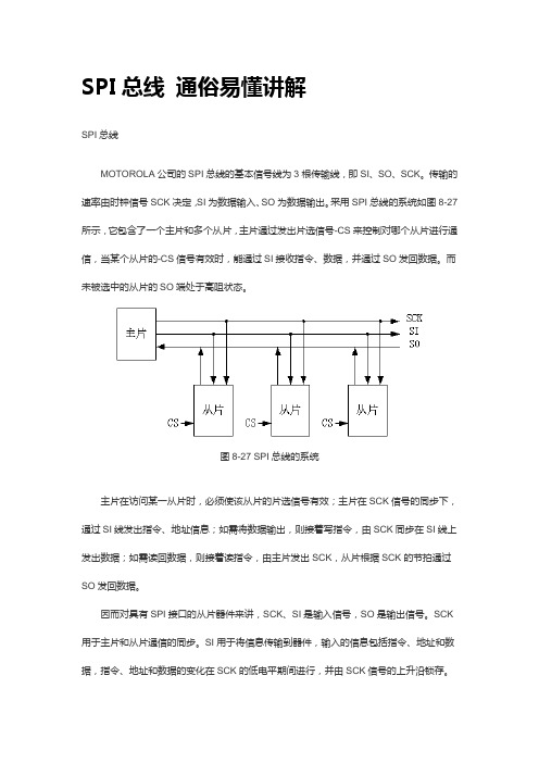
采用SPI总线的系统如图8-27所示,它包含了一个主片和多个从片,主片通过发出片选信号-CS来控制对哪个从片进行通信,当某个从片的-CS信号有效时,能通过SI接收指令、数据,并通过SO发回数据。
而未被选中的从片的SO端处于高阻状态。
图8-27 SPI总线的系统主片在访问某一从片时,必须使该从片的片选信号有效;主片在SCK信号的同步下,通过SI线发出指令、地址信息;如需将数据输出,则接着写指令,由SCK同步在SI线上发出数据;如需读回数据,则接着读指令,由主片发出SCK,从片根据SCK的节拍通过SO发回数据。
因而对具有SPI接口的从片器件来讲,SCK、SI是输入信号,SO是输出信号。
SCK 用于主片和从片通信的同步。
SI用于将信息传输到器件,输入的信息包括指令、地址和数据,指令、地址和数据的变化在SCK的低电平期间进行,并由SCK信号的上升沿锁存。
SO用于将信息从器件传出,传出的信息包括状态和数据,信息在SCK信号的下降沿移出。
Microchip公司的25XX系列的串行E2PROM采用了SPI总线,该系列器件的性能如表8-2所示。
表8-2 Microchip公司的25XX系列的串行E2PROM型号25XX04025XX08025XX16025XX320容量4K(512 X 8bit)8K(1024 X 8bit)16K(4096 X 8bit)32K(4096 X 8bit)地址信号A0~A8A0~A9A0~A10A0~A11以25XX320为例,该器件是4K字节的E2PROM,结构如图8-28所示,接口信号为SCK、SI和SO,此外还具有-CS、-WP、-HOLD信号线。
其中-CS为器件选中信号,当此信号为低电平时器件被选中,高电平时器件处于等待状态。
SPI协议——精选推荐
SPI协议SPI介绍由于SPI(serial peripheral interface)总线占⽤的接⼝线少,通信效率⾼,并且⽀持⼤部分处理器芯⽚,因⽽是⼀种理想的选择。
SPI是利⽤4根信号线进⾏通信的串⾏接⼝协议,包括主/从两种模式。
4个接⼝信号为:串⾏数据输⼊(MISO,主设备输⼊、从设备输出)、串⾏数据输出(MOSI,主设备输出、从设备输⼊)、移位时钟(SCK)、低电平有效的从设备使能信号(cs)。
SPI 最⼤的特点是由主设备时钟信号的出现与否来确定主/从设备间的通信。
⼀旦检测到主设备的时钟信号,数据开始传输。
⽬录· SPI⼯作⽅式简介· SPI的数据传输· SPI⽤户逻辑· SPI基本原理与结构SPI⼯作⽅式简介· SPI是由美国摩托罗拉公司最先推出的⼀种同步串⾏传输规范,也是⼀种单⽚机外设芯⽚串⾏扩展接⼝。
SPI模式可以允许同时同步发送和接收8位数据,并⽀持4种⼯作⽅式: 1. 串⾏数据输出,对应RC5/SDO引脚; 2. 串⾏数据输⼊,对应RC4/SDI/SDA引脚; 3. 串⾏时钟,对应RC3/SCK/SCL引脚; 4. 从动⽅式选择,对应RA5/SS/AN4引脚。
SPI模式下与之相关的寄存器有10个,其中4个是与I2C模式共⽤的。
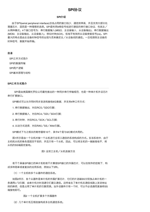
图1所⽰是由⼀个主机对接⼀个从机进⾏全双⼯通信的系统构成的⽅式。
在该系统中,由于主机和从机的⾓⾊是固定不变的,并且只有⼀个从机,因此,可以将主机的⼀端接⾼电平,将从机的SS端固定接地。
图1 全双⼯主机/从机连接⽅法 若⼲个具备SPI接⼝的单⽚机和若⼲⽚兼容SPI接⼝的外围芯⽚,可以在软件的控制下,构成多种简单或者复杂的应⽤系统,例如以下3种。
(1)⼀个主机和多个从器件的通信系统。
如图2所⽰,各个从器件是单⽚机的外围扩展芯⽚,它们的⽚选端SS分别独占单⽚机的⼀条通⽤I/O引脚,由单⽚机分时选通它们建⽴通信。
