收购天津港货运公司 90%股权的公告
夏普850,950,1100维修手册
(;(&87(
2.
默认值 495 495 495 150
监视器连接器
连接器
Pin No.
CN2
7
CN2
7
CN2
7
CN2
7
实际输出电压
–500±1V –500±1V –500±1V –150±1V
b) 在高压主电路板上的 CN2 pin (7) 连接器和 GND 之间连接一 个数字万用表。
CN2
MX-M850/M950/M1100 调 整 6 – 4
c) 用数字键数字键输入调整值, 然后按 [ 执行 ] 键。 机器输出显影偏压30 秒钟。
d) 用数字万用表检查输出电压。 如果输出电压超出上表规定范围, 则重复执行步骤2)-4), 直到 结果满足要求为止。 注意 : 如果更改调整值后仍无法使电压达到规定值范围以内 , 则以 下部件可能有故障: n 高压主电路板 n PCU 电路板 n 显影组件 n 高压电极
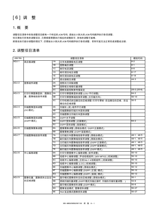
MX-M850/M950/M1100 调 整 6 – 1
Job No.
调整项目清单
模拟代码
ADJ 10 CCD校正
10A CCD 伽马调整 (CCD校正 ) ( 原稿台模式 )
63-3 (63-5)
10B CCD 伽马调整 (CCD校正 ) (DSPF模式 )
63-3
10C 彩色图像黑白转换调整
46-37
项目 / 显示 A COPY B PRINTER C FAX D PLUS
内容
显影偏压调整值 ( 复印模式 ) 显影偏压调整值 ( 打印机模式) 显影偏压调整值 (FAX 模式 ) 反向显影偏压调整值
指南]广州数控G90、G71指令格式及用法
![指南]广州数控G90、G71指令格式及用法](https://img.taocdn.com/s3/m/c394022b52d380eb63946d32.png)
如图所示。
外圆切削循环 ——G90
例2:应用圆锥面切削循环功能加工图c所示零件。 R=(40-50)/2
外圆切削循环 ——G90
例2:应用圆锥面切削循环功能加工图c所示零件。 R=(40-50)/2
例:应用端面切削循环功能加工如图f所示零件 ,每次切深4mm。 …… G00 X53 Z10;
G94 X20 Z6 R-11 F40; ?; ?; ?;
……
内、外圆端(锥)面切削循环 ——G94
例:应用端面切削循环功能加工如图f所示零件 ,每次切深4mm。 …… G00 X53 Z10;
G94 X20 Z6 R-11 F40; Z2; Z-2; Z-6; ……
值。
在增量编程中,地址U和W 后面数值的符号取决于轨迹1和 轨迹2的方向。在图中,U和W
后的数值取负号。
外圆切削循环 ——G90
例:应用圆柱面切削循环功能加工图所示零件 ,每次切削5mm
N10 G00 X100 Z100 T01; N20 M03 S600; N30 G00 X55 Z4; N40 G01 Z2 F40;
图d 端面切削循环
内、外圆端(锥)面切削循环 ——G94
书写格式 G94 X(U)… Z(W)… R… F… 式中:X、Z- 端面切削的终点坐标值
; U、W-端面切削的终点相对于循环起
点的坐标; R- 端面切削的起点相对于终点在Z轴
方向的坐标分量。 当起点Z向坐标小于终点Z向坐标时K
为负,反之为正。如图所示。
N10 T01; N20 M03 S600; N30 G00 X65 Z2; N50 G90 X60 Z-25 R-5 F60;
SCPQ-90中文资料
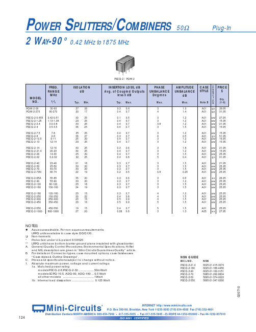
JYPQ
LRPQ-J
INSERTION LOSS, dB Avg. of Coupled Outputs less 3 dB
PHASE UNBALANCE
Degrees
Typ. Max.
0.2
0.7
0.2 0.7 0.2 0.7
0.45 1.4 0.5 1.0 0.2 0.5 0.2 0.6 0.5 1.1
21 18 30 20 30 20 22 19
35 20 30 20 25 18 24 19
23 15 30 22 23 16 23 16
19 15 27 20
PSCQ-2 / PQW-2
INSERTION LOSS, dB Avg. of Coupled Outputs
less 3 dB
Typ. Max.
1a. Matched power rating models PSCQ-2-8,PSCQ-2-32 ................... 50mWatt models SCPQ-10.5, ADQ-90, ADQ-180 ... 0.5 Watt all other models ...................................... 1Watt
6
7
3
6
NOT USED
—
—
—
—
—
gx 1 2 5 3,4,7,8 — — —
gy 1 2(0°) 6(90°) 3,4,7,8
5 —
hm
ja
9
1
2(0°)
8
6(-90°)
14
1,3,4,5,7,8 2,3,4,5,6,9
10,11,12,14 10,11,12,13
数控铣手工编程

工件
刀具
刀具半径补偿(G41、G42、G40)
左刀补:沿着刀具前进方向刀具在工 件轮廓左侧的补偿
右刀补:沿着刀具前进方向刀具在工 件轮廓右侧的补偿
刀具半径补偿(G41、G42、G40)
指令格式:
刀具半径补偿的建立:
XY
XZ
D
YZ
刀具补偿号
刀具补偿起刀时必须为G00或G01 左、右刀补的设置
刀具半径补偿(G41、G42、G40)
螺旋线进给G02/G03
说明 1.X, Y, Z 中由G17/G18/G19 平面选定的两个坐标为螺旋线投影圆弧的终点 意义同圆弧进给第3 坐标是与选定平面相垂直的轴终点其余参数的意义同圆弧进 给。 2.该指令对另一个不在圆弧平面上的坐标轴施加运动指令对于任何小于360 的 圆弧可附加任一数值的单轴指令。
G90 时为中间点在工件坐标系中的坐标。 G91 时为中间点相对于起点的位移量。
G28 指令首先使所有的编程轴都快速定位到中间点,然后再从中间 点返回到参考点。
一般G28 指令用于刀具自动更换或者消除机械误差,在执行该指 令之前应取消刀具半径补偿和刀具长度补偿。
自动返回参考点G28
利用G28从当前点直接回参考点:
该指令使刀具以F指定的进给速度插补加
工出任意斜率的直线, 指令格式如下: G01 X__ Y __ Z __ F __ ;
其中, X、 Y、 Z为直线的终点坐标, 可以是绝对坐标, 也可以是增量坐标, 不移动的坐标轴可以省略; F为刀具移 动的速度, 单位为mm/min。
直线插补(G01)
直线插补编程实例:
圆弧半径 圆弧终点的坐标值
圆弧插补G02/G03
圆弧的终点位置与圆心
Linux系统内存占用90%以上——解决方法

Linux系统内存占⽤90%以上——解决⽅法Linux系统内存占⽤90%以上,是否属于正常范围?Linux/Unix系统管理内存的⽅式和windows是不⼀样的,即便是⼀个负载很⼩的linux,跑⼏天后,内存占⽤量也将达到90%以上,即便⽆⼈访问,这个数字是完全正常的。
但是,这个内存占⽤量不会达到100%的,每天夜⾥系统都会执⾏/etc/cron.dail Linux/Unix系统是⾮常稳健的,虽然内存占⽤显⽰90%以上,但依然可保证365天以上⽆须重启。
对于Linux系统,评估其压⼒的主要指标是最近5分钟的负载指数:⽐如⽤w命令或者top去看,可以看到“0.70 0.35 0.01”这样的数字,分别表⽰5分钟内的1)有程序占⽤⼤量CPU,使⽤top命令来检查(看看是否有java程序锁死之类的故障)2)有程序占⽤⼤量内存,使得内存真正不够⽤了(这个才是真正需要加内存的时候),⽐如由于MySQL在较⼤负载下运⾏容量为GB级别的数据库导致内存不够⽤,需要给服务器插⼊更多物理内存3)磁盘系统读写故障,IO吞吐错误造成CPU负载上升,需要光盘引导进⼊单⽤户模式扫描修复磁盘,修不好就只能更换新硬盘了因此,对于Linux/Unix系统内存占⽤的百分⽐,⽆须过于关⼼,⼀般检查系统负载参数即可但也可以⼿动进⾏内存释放,具体操作如下:cat /proc/sys/vm/drop_caches⾸先,/proc/sys/vm/drop_caches的值,默认为0free⼀下查看当前内存可使⽤的较少,执⾏⼀下以下的命令,可以解决当前的问题echo 3 > /proc/sys/vm/drop_caches 结果cat /proc/sys/vm/drop_caches3再来运⾏free命令,发现现在的used为66MB,free为182MB,buffers为0MB,cached为11MB.那么有效的释放了buffer和cache. 。
2017一年级语文下册生字组词表(鄂教版6-10课)

2017一年级语文下册生字组词表(鄂教版6-10课)2017?-10璇撅級绗?璇?涓夊彧灏忔澘鍑?鍥?鍥犱负璧峰洜鍘熷洜鍥犲惊瀹堟棫浜嬪嚭鏈夊洜鍥犱汉鎴愪簨浜?浜ら泦浜ら檯浜ゅ線浜ら€?浜や唬浜ょ晫浜ゆ祦楗ュ瘨浜よ揩浣?浣滅敤鍙戜綔鍔充綔鎿嶄綔涓€榧撲綔姘?浠ヨ韩浣滃垯鑻︿腑浣滀箰甯?鍙戝竷鍒嗗竷鐢诲竷甯冪疆瀹e竷甯冨眬寮€璇氬竷鍏?鏄熺綏妫嬪竷涓?涓€涓?鏂や袱涓ゅ崐涓変笁涓や袱鍗婃枻涓夐暱涓ょ煭宸?宸﹀彸宸﹁竟宸︽墜宸﹀彸寮€寮?鏃侀棬宸﹂亾宸﹀彸涓洪毦宸﹀彸閫㈡簮鍙?鍙宠竟鍙虫墜鍙虫淳鏃犲嚭鍏跺彸宸﹂偦鍙宠垗宸﹂【鍙崇浖瀹?鍏跺畠瀹冧滑鏃犲畠瀹冩棩瀹冨北涔嬬煶瀹冩晠瀹冨勾绗?璇?鏄庡ぉ鍐嶇粌鍚?缁?宸茬粡鏇撅紙c茅ng锛夌粡缁忚繃缁忓吀缁忔祹缁忛獙澶╃粡鍦颁箟杩?杩愬姩杩愯緭锛坰h奴锛?绌鸿繍杩愭皵濂借繍鍛借繍鏃舵潵杩愯浆鍔?娲诲姩鍔ㄩ潤鍔ㄧ墿鍔冲姩鍔ㄤ綔鎯婂ぉ鍔ㄥ湴琛屽姩ch菙n锛夎牏娆插姩鍛?杩愬姩鍛?瀛﹀憳婕斿憳鍔ㄥ憳浜哄憳鍏氬憳骞咃紙f煤锛夊憳杈介様濮?寮€濮?鍒涳紙chu脿ng濮嬬粓濡備竴鍛ㄨ?闃?闃存殫闃存.闃磋皨锛坢贸u锛?闃撮櫓锛坸i菐n锛?鏍戦槾闃村巻闃村樊闃抽敊浣?璁颁綇鎶撲綇鐣欎綇浣忔埧浣忔墜鍋滀綇鎷涙灦涓嶄綇寰?锛坉臎i锛?寰楄蛋浜?寰楁敞鎰忎簡鎸猴紙t 菒ng锛夊緱鏄?鏄庡勾鍏夋槑閫忥紙t貌u锛夋槑绮撅紙j墨ng锛夋槑鑻辨槑鏄庣煡鏁呴棶鍐?鍐嶇増锛坆菐n锛?鍐嶄笁鍐嶆帴锛坖i膿锛夊啀鍘夛紙l矛锛?鏈轰細闅惧啀宸?宸茬粡鏃╁凡宸茬劧鏈ㄥ凡鎴愯垷褰?褰撻€?鎷咃紙d膩n锛夊綋褰撴椂褰撳績褰撳垵鐞嗘墍褰撶劧鏃?鏃╂櫒娓呮棭鏃╂櫄杩熸棭瓒佹棭鏃╃潯鏃╄捣鏃╁嚭鏅氬綊瑷€鍙戣█鍚嶈█鏂囪█瑷€璁?鏈夎█鍦ㄥ厛涓€瑷€涓哄畾搴?搴婂墠搴婇摵璧峰簥璧栧簥娌冲簥鐗欏簥杞﹀簥鍗у簥鏈?鑺辨湹浜戞湹鑰虫湹?涓€鏈典袱鏈?澶у揩?绗?璇?灏忕敾鐪?鐪?鐪夌洰鐪夋瘺鐢荤湁楦?鐨辩湁鐪夊ご鐪夋ⅱ鐪夊畤娴撶湁澶х溂鎵鍒囷紙qi猫锛?鎬ュ垏鍏冲垏瀵嗗垏鐪熷垏璐达紙ti膿锛夊垏?璞?澶ц薄姘旇薄涓囧崈鍗拌薄涓囪薄鏇达紙g膿ng锛夋柊璞″緛寮?寮哄.椤絯谩n寮?鍧氬己鍕夛紙mi菐n锛夊己寮鸿揩寮澹?ぇ鑼侊紙zu贸锛夊.鐞嗙洿姘斿.骞诧紙g膩n锛?骞插噣骞茬嚗骞叉澂骞叉棻骞叉秹骞茬埞涓€骞蹭簩鍑€澶у姩骞叉垐锛坓膿锛?鍚?鍛煎惛鍚稿紩鍚告敹鍚哥儫鍚稿彇鍚哥儹鍚告瘨锛坉煤锛?寮?鎸囧紩鍕惧紩寮曞姏寮曠敤寮曞彿绌块拡寮曠嚎寮曚汉鍏ヨ儨濡?涓猴紙w猫i锛?涓轰簡鍥犱负涓轰粈涔?涓轰綍涓哄浗鎹愶紙ju膩n锛夎函锛坬奴锛?涓烘皯璇峰懡鍔?鍔涢噺鑳藉姏瑙嗗姏鏅哄姏缁欏姏鍏ㄥ姏浠ヨ荡己鍔涘.璁?璁板綍璁板繂璁版€?浠?浠ヤ负鎵€浠?浠ュ悗浠ュ強浠ヤ竴褰擄紙d脿ng锛夊崄浠ュ皬瑙佸ぇ浠ュ嵉锛坙u菐n锛夊嚮鐭?浠?鍛戒护娉曚护鍙d护浠ゅ皧鍘夸护缁曞彛浠?浠や汉绁炲線鍐涗护濡傚北濂?濂圭殑濂逛滑鑰?鎮﹁€?鑰虫湹鑰崇幆鑰冲瀭鑰宠儗鑰虫満榛戞湪鑰?鍏呰€充笉闂?绗?璇?鎵炬ⅵ姊?姊︽兂缇庢ⅵ锛岀潯姊?姊﹀够绾㈡ゼ姊?榛勭脖锛坙i谩ng锛変竴姊?濡傛ⅵ鍒濋啋瑙夛紙ji脿o锛?涓€瑙夐啋锛坸菒ng锛夋潵鍝???鏋?鏋曞ご钀斤紙l脿o锛夋灂鏋曞腑鏋曟湪楂樻灂鏃犲咖鏋曟垐锛坓膿锛夊緟锛坉脿i锛夋棪琚?w霉锛?绐?鐕曠獫閰掔獫绐濈獫澶?铚傜獫鐪肩獫鍏斿瓙涓嶅悆绐濊竟鑽?绐?绐楁埛瑙嗙獥寮€绐?绐楀笜鍚岀獥绐楁槑鍑狅紙j墨锛夊噣鎵撳紑澶╃獥璇翠寒璇?鎵?瀵绘壘鎵惧埌鎵鹃綈鎵鹃挶鏌ユ壘鎵捐ˉ?鑷鍒?鍒拌揪鍛ㄥ埌鍒板簳杩熷埌閬囧埌鐧藉ご鍒拌€?姛鐭?鐭ラ亾鐭ヨ瘑鐭ユ檽鐭ュ繁閫氱煡涓嶇煡鎵€cu貌锛?鐪?鐪嬩功鐪嬬梾鐓х湅鐪嬫湜瑙傜湅闅剧湅gu膩锛夌洰鐩哥湅娌?娌℃湁娌′簨娌¤瘽娌$┖娌¢挶娌″叧绯?娌″畬娌′簡娌″ぇ娌″皬鍏?鍏抽敭锛坖i脿n锛?鍏宠妭鍏冲績鐩稿叧鍏抽棴寮€鍏?杩囧叧鏂╁皢锛坖i脿ng锛?濂?濂藉潖缇庡ソ鍙嬪ソ濂藉喎姝eソ鑺卞ソ鏈堝渾鍚?鍚堜綔缁勫悎鍚堝敱闆嗗悎鍚堜簩涓轰竴鍚堢悊涓嶈皨锛坢贸u锛夎€屽悎銆婃偗鍐溿€?鍐?鍐滀笟鍐滄潙鍐滄皯鍐滅敯鍐滃簞鍔″啘鍔犲啘鐐?閲嶅啘杞诲晢锛坰h膩ng锛?鍗?涓婂崍鍗堥キ姝e崍鏅岋紙sh菐ng锛夊崍w猫i锛夌緤鍗堟椂涓夊埢姹?姹楁按娴佹睏鍑烘睏姹楁祦娴冿紙ji谩锛夎儗绮?璞嗙矑绫崇矑璋风矑棰楃矑涓€绮?绮掑瓙绮掑緞绮掔矑鐨嗚緵鑻?杈?杈涜嫤杈涘嫟鑹拌緵杈涜荆锛坙脿锛?杈涢吀涓嶈緸锛坈铆锛夎緵鍔?鍗冭緵涓囪嫤?绗?绗涘瓙绔圭瑳鐗э紙m霉锛夌瑳绗涘0椋庣瑳闀跨瑳绗涙洸鏌崇瑳鍚圭瑳濂?濂囨€?濂囧紓濂囩壒濂囬椈濂囨墠鎯?妞?搴фzhu脿n妞呭瓙妞呰儗澶存璇嗗瓧锛堜簩锛?鐚?鐚滆皽鐚滄兂鐚滄祴c猫鐚滅枒鐚滀腑锛坺h貌ng锛?涓ゅ皬鏃犵寽鑳$寽涔辨兂褰?鐢靛奖褰卞瓙骞诲奖鎽剆h猫褰?褰卞搷濡傚奖闅忥紙su铆锛夊舰涓?涓㈠け涓㈠純涓㈡帀涓㈠垎笁钀藉洓涓㈢洈寮冪敳鍔?浣垮姴鐢ㄥ姴鏉ュ姴骞插姴鍔查亾璐癸紙f猫i锛夊姴?鍚庡姴鍗佽冻寮癸紙d脿n锛夊瓙寮?寮瑰紦瀵煎脊鍘熷瓙寮?鏍稿脊澶?洦寮逛父涔嬪湴璺?璺抽珮璺宠穬璺崇怀璺虫按璺虫Ы锛坈谩o锛?璺充紴璺虫澘韫︼紙b猫ng锛?韫﹁烦璺?鎶?鎶撲綇 鎶撴崟锛坆菙锛?鎶撶揣 鎶撳績鎸狅紙n 谩o 锛夎倽 澶村彂鑳″瓙涓€鎶婃姄 妫?妫嬪瓙 妫嬭壓 妫嬬洏 妫嬪眬?娌?娌欐哗 娌欐紶 娌欐紡锛坙貌u 锛?娌欏湡 娌欏彂 娌欏搼锛坹菐锛?鎹?鎹曪紙b 菙锛夋崏 鎹変綇 鎹夋嬁锛坣谩锛?娲绘崏 鎹夌瑪 鎹夊垁 鎹夊紕杩? 鐚滆皽 杩疯矾 杩峰け 杩蜂汉 鐫€杩?鐞冭糠 鎵э紙zh 铆锛夎糠涓嶆偀锛坵霉锛?鐝?寮癸紙d 脿n 锛夌彔 鐝嶇彔 鏄庣彔 闇茬彔 鐝犵畻 楸肩洰娣穐霉n 鐝?鐝犲厜瀹濇皵 鐨?鐗涚毊椤絯谩n 鐨?姗$毊 ?楦℃瘺钂滐紙su 脿n 锛夌毊 閾?閽㈤搧 閾佸尃锛坖i 脿ng 锛?鎵撻搧 閾佽矾 鍦伴搧 鎵嬫棤瀵搁搧 鐜?鑰崇幆 鍏夌幆 x 煤n 锛夌幆鎴?涔︽埧ch 煤锛夋埧 鎴垮眿 蹇冩埧 鏂囨埧鍥涘疂绗?0璇?椋?浣?浣嗘槸 浣嗗嚒 浣嗘効 涓嶄絾 闈炰絾銆?鍊?鍊欓笩 姘斿€???灏忔椂鍊?鏈夋椂鍊?楦¢福鍊欐棪鍊欒壊 鍒?鍒氱儓 闃冲垰 鍒氬ソ 鐧剧偧鎴愬垰 浠ユ煍鍒跺垰澶栨煍鍐呭垰 娓?娓告垙 鐣呮父 浜戞父 瀵兼父娓稿垉鏈変綑 娓稿北鐜╂按 鎴?鎴忔洸 婕旀垙 鎴忔按 鎴忓紕 鎴忔硶 闈炲悓鍎挎垙 瑙嗕负鍎挎垙 閫㈠満浣滄垙 鏍?鏍戞湪 鏍戣嫍鍔?鍔ㄦ満 鍔ㄤ綔 鍔ㄥ惉 鍔ㄧ墿 鍔ㄦ€?涓€涓句竴鍔?鎯婂ぉ鍔ㄥ湴鏃?鏃堕棿 鏃惰妭 鏃朵唬 鏃朵护 鏃舵満 鏃舵晥 鏃舵潵杩愯浆 鏃舵椂鍒诲埢 閭?閭d箞 閭i噷 閭d簺 閭h竟 閭f椂鍊?鐐?鐐圭牬 鍦扮偣 瑕佺偣 鐐瑰皢 璧风偣 鐢婚緳鐐圭潧 鐐圭煶鎴愰噾 鎸囩偣姹熷北 娌?娌虫祦 娌虫按 娌冲窛 娌抽槻 娌冲北 榛勬渤 闀挎渤 娌虫竻娴锋檹 姘斿.灞辨渤 璧?璧疯壊 璧峰眳璧蜂紡 璧疯崏 椋庣敓姘磋捣娉?娉㈡氮 娉㈡姌 娉㈤暱 娉㈠姩 娉㈠強 ? 杞╃劧澶?娉?绔圭儫娉㈡湀。
数控加工中心常用G-M代码指令详解
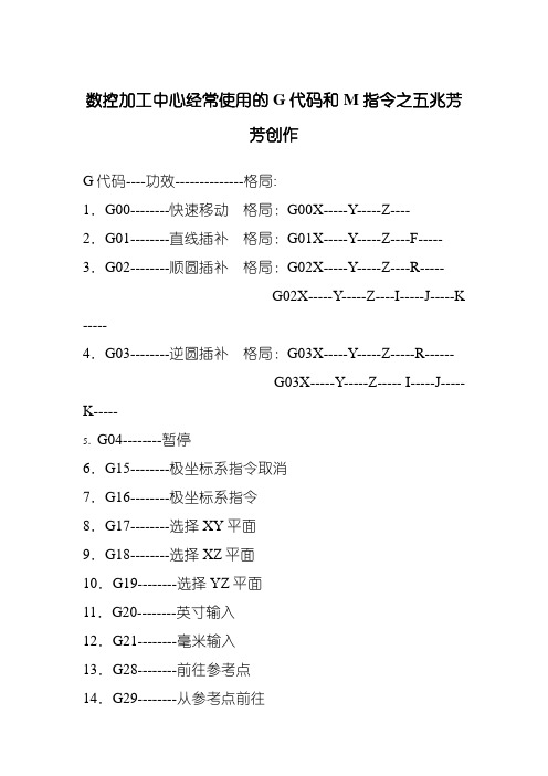
数控加工中心经常使用的G代码和M指令之五兆芳芳创作G代码----功效--------------格局:1.G00--------快速移动格局:G00X-----Y-----Z----2.G01--------直线插补格局:G01X-----Y-----Z----F----- 3.G02--------顺圆插补格局:G02X-----Y-----Z----R-----G02X-----Y-----Z----I-----J-----K -----4.G03--------逆圆插补格局:G03X-----Y-----Z-----R------G03X-----Y-----Z----- I-----J-----K-----5.G04--------暂停6.G15--------极坐标系指令取消7.G16--------极坐标系指令8.G17--------选择XY平面9.G18--------选择XZ平面10.G19--------选择YZ平面11.G20--------英寸输入12.G21--------毫米输入13.G28--------前往参考点14.G29--------从参考点前往15.G40--------刀具半径抵偿取消16.G41--------刀具半径左抵偿17.G42--------刀具半径右抵偿18.G43--------正向刀具长度抵偿19.G44--------负向刀具长度抵偿20.G49--------刀具长度抵偿取消21.G50--------比例缩放取消22.G51--------比例缩放有效23.G54~G59选择工件坐标系1~~~624.G68--------坐标旋转25.G69--------坐标旋转取消26.G73--------高速深孔钻循环格局:G73X---Y---Z---R---Q---F---K---27.G74--------左旋攻丝循环格局:G74X---Y---Z---R---Q---F---K---28.G76--------精镗循环格局:G76X---Y---Z---R---Q---P---F---K---29.G80--------取消固定循环30.G81--------钻孔循环格局:G81X---Y---Z---R---F--- 31.G83--------排屑钻孔循环格局:G83X---Y---Z---R---Q---F---K---32.G84--------刚性攻丝循环格局:G84X---Y---Z---R---P---F---K---33.G90--------绝对值编程34.G91--------增量值编程35.G94--------每分钟进给36.G95--------每转进给37.G98--------固定循环前往到参考点38.G99--------固定循环前往到R点经常使用的帮助功效M代码M代码----功效1. M00--------程序停止2. M01--------选择停止3. M02--------程序结束4. M03--------主轴正转5. M04--------主轴反转6. M05--------主轴停止转动7. M06--------换刀指令8. M08--------切削液开9. M09--------切削液关10.M19-------主轴定位11.M30-------程序结束,并前往程序起始12.M98-------子程序调用13.M99-------子程序结束,并前往主程序地址码中英文字母的寄义地址------功效---------寄义1.D------------抵偿号--------刀具半径抵偿指令2.F------------进给速度------给速度的指令3.G------------准备功效-----指令动作方法4.H------------抵偿号--------抵偿号的指定5.I-------------坐标字--------圆弧中心X轴向坐标6.J-------------坐标字--------圆弧中心Y轴向坐标7.K------------坐标字--------圆弧中心Z轴向坐标8.L------------重复次数-----固定循环及子程序的重复次数 9.M-----------帮助功效-----机床开/关指令10.N----------顺序号--------程序段顺序号11.O----------程序号--------程序号,子程序号的指定12.P----------------------------暂停或程序中某功效开始使用的顺序号13.Q----------------------------固定循环终止段号或固定循环中定距14.R----------坐标字---------固定循环中定距离或圆弧半径的指令15.S----------主轴功效------主轴转速的指令16.T----------刀具功效------刀具编号的指令17.X---------坐标字----------X轴的绝对坐标值或暂停时间18.Y---------坐标字----------Y轴的绝对坐标19.Z---------坐标字----------Z轴的绝对坐标功效详解:G00—快速定位格局:G00 X(U)__Y(W)__说明:(1)该指令使刀具依照点位控制方法快速移动到指定位置.移动进程中不得对工件进行加工.(2)所有编程轴同时以参数所定义的速度移动,当某轴走完编程值便停止,而其他轴持续运动,(3)不运动的坐标无须编程.(4)G00可以写成G0G01—直线插补格局:G01 X(U)__Y(W)__F__(mm/min)说明:(1)该指令使刀具依照直线插补方法移动到指定位置.移动速度是由F指令进给速度.所有的坐标都可以联动运行.(2)G01也可以写成G1两轴联动从A点到B点G02—顺圆插补格局1:G02 X(u)____Y(w)____I____J____F_____说明:(1)X、y在G90时,圆弧终点坐标是相对编程零点的绝对坐标值.在G91时,圆弧终点是相对圆弧起点的增量值.无论G90,G91时,I和J 均是圆弧终点的坐标值.I是X标的目的值、J是y标的目的值.圆心坐标在圆弧插补时不得省略,除非用其他格局编程.(2)G02指令编程时,可以直接编过象限圆,整圆等.注:过象限时,会自动进行间隙抵偿,如果参数区末输入间隙抵偿与机床实际反向间隙悬殊,都会在工件上产生明显的切痕.(3)G02也可以写成G2.例:G02 X60 Y50 I40 J0 F120格局2:G02 X(u)____Y(w)____R__F__说明:(1)不克不及用于整圆的编程(2)R为工件单边R弧的半径.例:G02 X60 Y50 R20 F120G03—顺圆插补说明:除了圆弧旋转标的目的相反外,格局与G02指令相同. G04—定时暂停格局:G04__X__ 或G04 _P_说明:加工运动暂停,时间到后,持续加工.暂停时间由X 前面的数据指定.单位是秒.规模是0.01秒到300秒.G54—设定工件坐标一格局:G54说明:在系统中可以有几个坐标系,G54对应于第一个坐标系,其原点位置数值在机床参数中设定.G55—设定工件坐标二同上G56—设定工件坐标三同上G57—设定工件坐标四同上G58—设定工件坐标五同上G59—设定工件坐标六同上G90—绝对值方法编程格局:G90说明:(1)G90编入程序时,以后所有编入的坐标值全部是以编程零点为基准的.(2)系统上电后,机床处在G状态.N0010 G90 X20Y90N0020 G01 X40 Y80 F100N0030 M02G91—增量方法编程格局:G91说明:G91编入程序时,之后所有坐标值均以前一个坐标位置作为起点来计较运动的编程值.在下一段坐标系中,始终以前一点作为起始点来编程.例:N0010 G91 X20Y85N0020 G01 X20 Y-10 F100N0030 Y-20N0040 X20Y-15N0050 M02注意事项:弥补一下:1、G00与G01G00运动轨迹有直线和折线两种,该指令只是用于点定位,不克不及用于切削加工G01按指定进给速度以直线运动方法运动到指令指定的目标点,一般用于切削加工2、G02与G03G02:顺时针圆弧插补G03:逆时针圆弧插补3、G04(延时或暂停指令)一般用于正反转切换、加工盲孔、阶梯孔、车削切槽4、G17、G18、G19 平面选择指令,指定平面加工,一般用于铣床和加工中心G17:X-Y平面,可省略,也可以是与X-Y平面相平行的平面G18:X-Z平面或与之平行的平面,数控车床中只有X-Z平面,不必专门指定G19:Y-Z平面或与之平行的平面5、G27、G28、G29 参考点指令G27:前往参考点,查抄、确认参考点位置G28:自动前往参考点(经过中间点)G29:从参考点前往,与G28配合使用6、G40、G41、G42 半径抵偿G40:取消刀具半径抵偿7、G43、G44、G49 长度抵偿G43:长度正抵偿G44:长度负抵偿G49:取消刀具长度抵偿8、铣床、加工中心:G73:高速深孔啄钻G83:深孔啄钻G81:钻孔循环G82:深孔钻削循环G74:左旋螺纹加工G84:右旋螺纹加工G76:精镗孔循环G86:镗孔加工循环G85:铰孔G80:取消循环指令9、编程方法G90、G91G90:绝对坐标编程G91:增量坐标编程10、主轴设定指令G99:前往到R点(中间孔)G98:前往到参考点(最后孔)11、主轴正反转停止指令M03、M04、M05M03:主轴正传M04:主轴反转M05:主轴停止12、切削液开关M07、M08、M09M07:雾状切削液开M08:液状切削液开M09:切削液关13、运动停止M00、M01、M02、M30M00:程序暂停M01:筹划停止M02:机床复位M30:程序结束,指针前往到开头14、M98:调用子程序15、M99:前往主程序。
FANUC_刻字宏程序+旋转90度__FANUC宏程序_加工中心刻字宏程序

刀具号刀具类型刀具材料刃长伸出长度夹头规格刀具分布/刀具状态11BNS21500I 1911J 2022K2133L 2244M 2355N 2466O 2577P 2688Q 2799R 28-10S 29A 11T 30B 12U 31C 13V 32D 14W 33E15X 34F 16Y 35G 17Z 36H18空格 37字高#3的数值#1初始位数1.5#3=0.6#2刻字位数2#3=0.8#3缩放倍数2.5#3=1.0#4刻字间距3#3=1.23.5#3=1.4#6字间变量4#3=1.6#7刻字深度#8字间变量#2=刻字位数,多于位数的字就不刻了。
(下图第22-24位的字就不刻了)只要修改刻字内容和刻字位数其它不用变。
对应的刻字内容刻字内容刻字代号根据需要不用变不用变默认=2.5可适当调整刀 具 单客户名称:图纸号: 刻字宏程序旋转90度加工步骤工件大于42.29刻一行,工件在25.65-42.29之间刻二行,工件小于25.65就不要用此程序刻。
加工材料:需要用到缩放功能时请去除G50和G51X0Y0I#3J#3的括号只有Hartford 支持此功能缩放倍数表变量刻字内容刻字代号不用变跟据刻字位数根据比例刻字宏程序REV11.刻字范围0-9 A-Z2.刻字位数243.支持字高1.5-4MM4. 刻字宏程序文件大小8KB5.把O0001到M30之间内容复制到记事本,保存成NC文件。
6.M98P9002是一此初始指令和取消指令,下载后可以另存为其它名字.O0001(AUTOMANTION KEZI ROTATION 90 ANGLE)G90G10L2P0X0Y0.0Z0.05G90G10L2P1X0.Y0.Z0M98P9002#10=29(1)#11=17(2)#12=1(3)#13=2(4)#14=3(5)#15=4(6)#16=5(7)#17=6(8)#18=7(9)#19=8(10)#20=9(11)#21=10(12)#22=11(13)#23=10(14)#24=23(15)#25=0(16)#26=4(17)#27=9(18)#28=15(19)#29=0(20)#30=2(21)#31=2(22)#32=2(23)#33=2(24)#2=21( KE ZI WEI SHU)#3=1.0(SUO FANG BEI SHU)#1=0(CHU SHI BIAN LIANG)#4=2.5(ZI JIAN JU)#6=[#3*#4](KE ZI JIAN JU BIAN LIANG)#7=-.05(KE ZI SHEN DU)G90G52X0Y0( 1BNS )N100T1M6G90G10L12P60R0.00G90G54G0X0Y0S3000M3 G43H#4120Z5./M8(G50)G90G52X0Y0(G51X0Y0I#3J#3)N1#1=[#1+1](BIAN LIANG) IF[#1LE#2]GOTO[#1+99](G50)G90G52X0Y0GOTO99N100GOTO[#10+10]N101GOTO[#11+10]N102GOTO[#12+10]N103GOTO[#13+10]N104GOTO[#14+10]N105GOTO[#15+10]N106GOTO[#16+10]N107GOTO[#17+10]N109GOTO[#19+10]N110GOTO[#20+10]N111GOTO[#21+10]N112GOTO[#22+10]N113GOTO[#23+10]N114GOTO[#24+10]N115GOTO[#25+10]N116GOTO[#26+10]N117GOTO[#27+10]N118GOTO[#28+10]N119GOTO[#29+10]N120GOTO[#30+10]N121GOTO[#31+10]N122GOTO[#32+10]N123GOTO[#33+10]G1Z#7F100.G3 X-.408 I.842 J2.316 F300.Y1.316 I-.208 J.584X-2.092 I-.842 J-2.316Y.148 I.208 J-.584G0 Z5.G52G90X0Y#6#6=[#6+#8]GOTO1N11 (1)X0. Y.714Z5.Z1.G1Z#7F100.Y.357 F300.X-2.5X-2.143 Y0.G0 Z5.X0.Z1.G1Z#7F100.Y.357 F300.G0 Z5.G52G90X0Y[#6-[#8*0.4]]#6=[#6+[#8*0.6]]GOTO1N12 (2)X-2.143 Y.054Z5.Z1.G1Z#7F100.G2 X-2.5 Y.672 I.357 J.619 F300. G1 Y.728G2 X-1.818 Y1.441 I.714 J0.X-1.37 Y1.257 I-.032 J-.714X-.891 Y.615 I-4.503 J-3.861G3 X0. Y0. I1.057 J.58G1 Y1.495G0 Z5.N13(3)X-2.143 Y.036Z5.Z1.G1Z#7F100.G2 X-2.5 Y.658 I.364 J.622 F300. G1 Y.75G2 X-2.305 Y1.269 I.788 J0.X-1.875 Y1.464 I.43 J-.376X-1.252 Y.933 I0. J-.631G1 Y.755G0 Z5.Y.933Z1.G1Z#7F100.G2 X-.625 Y1.5 I.627 J-.064 F300. X-.195 Y1.305 I0. J-.571X0. Y.786 I-.593 J-.519G1 Y.622G2 X-.357 Y0. I-.721 J0.G0 Z5.G52G90X0Y#6#6=[#6+#8]GOTO1N14(4)X-.589 Y1.661Z5.Z1.G1Z#7F100.Y0. F300.X-2.5 Y1.295X0.G0 Z5.G52G90X0Y#6#6=[#6+#8]GOTO1N15(5)X-.355 Y0.Z5.Z1.X-1.25 Y1.429 I-.405 J-.708X-1.507 Y1.137 I.42 J-.63X-1.607 Y.714 I.846 J-.423X-1.393 Y0. I1.153 J-.043G1 X-2.5Y1.511G0 Z5.G52G90X0Y#6#6=[#6+#8]GOTO1N16(6)X-.565 Y.093Z5.Z1.G1Z#7F100.G3 X-.515 Y1.522 I-.179 J.722 F300. X-.967 Y.107 I-.226 J-.708X-.565 Y.093 I.226 J.708G2 X-1.992 Y.143 I-.64 J2.133X-2.128 Y1.498 I.228 J.708G0 Z5.G52G90X0Y#6#6=[#6+#8]GOTO1N17(7)X-2.5 Y0.Z5.Z1.G1Z#7F100.Y1.5 F300.G3 X0. Y.75 I2.5 J3.793G0 Z5.G52G90X0Y#6#6=[#6+#8]GOTO1N18(8)X-1.339 Y.67X-2.5 Y.83 I0. J-.58G1 Y.67G3 X-2.434 Y.401 I.58 J0.X-1.339 Y.67 I.515 J.268X-.289 Y.119 I.67 J0.X0. Y.67 I-.381 J.551G1 Y.83G3 X-.67 Y1.5 I-.67 J0.X-1.339 Y.83 I0. J-.67G0 Z5.G52G90X0Y#6#6=[#6+#8]GOTO1N19(9)X-1.985 Y.034Z5.Z1.G1Z#7F100.G3 X-1.532 Y1.449 I.226 J.708 F300. X-1.935 Y1.463 I-.226 J-.708X-1.985 Y.034 I.179 J-.722G0 Z5.X-1.935 Y1.463Z1.G1Z#7F100.G2 X-.507 Y1.413 I.64 J-2.133 F300. X-.372 Y.057 I-.229 J-.707G0 Z5.G52G90X0Y#6#6=[#6+#8]GOTO1N20(-)X-1.25 Y0.Z5.Z1.G1Z#7F100.Y1.429 F300.G0 Z5.Y1.25G0 Z5.G52G90X0Y#6#6=[#6+#8]GOTO1N21(A)X-.536 Y.201Z5.Z1.G1Z#7F100.Y1.674 F300.X0. Y1.875G0 Z5.X-.536 Y1.674Z1.G1Z#7F100.X-2.5 Y.938 F300.X-.536 Y.201X0. Y0.G0 Z5.G52G90X0Y#6#6=[#6+#8]GOTO1N22(B)X-1.25 Y0.Z5.Z1.G1Z#7F100.X-.005 F300.Y.971G3 X-1.255 I-.625 J0.X-1.253 Y.928 I.625 J0.G1 X-1.25 Y0.X-2.5Y.866G2 X-1.253 Y.928 I.625 J0. G0 Z5.G52G90X0Y#6#6=[#6+#8]GOTO1Z1.G1Z#7F100.G3 X-1.964 Y.118 I.536 J-.747 F300. X-.536 I.714 J2.11X-.379 Y1.702 I-.38 J.837G0 Z5.G52G90X0Y#6#6=[#6+#8]GOTO1N24(D)X-2.5 Y0.Z5.Z1.G1Z#7F100.X0. F300.Y.697G3 X-.536 Y1.448 I-.915 J-.086X-1.964 I-.714 J-2.109X-2.5 Y.697 I.38 J-.837G1 Y0.G0 Z5.G52G90X0Y#6#6=[#6+#8]GOTO1N25(E)X-1.25 Y0.Z5.Z1.G1Z#7F100.X0. F300.Y1.466G0 Z5.X-1.25 Y1.145Z1.G1Z#7F100.Y0. F300.X-2.5Y1.466G0 Z5.G52G90X0Y#6X-1.25 Y0.Z5.Z1.G1Z#7F100.X0. F300.G0 Z5.X-1.25Z1.G1Z#7F100.X-2.5 F300.Y1.466G0 Z5.X-1.25 Y1.145Z1.G1Z#7F100.Y0. F300.G0 Z5.G52G90X0Y#6#6=[#6+#8]GOTO1N27(G)X-1.109 Y.634Z5.Z1.G1Z#7F100.Y1.764 F300.X-.845G2 X.016 Y.91 I-.011 J-.872 X-.536 Y.118 I-.872 J.019 X-1.964 I-.714 J2.11X-2.121 Y1.702 I.38 J.837 G0 Z5.G52G90X0Y#6#6=[#6+#8]GOTO1N28(H)X-2.5 Y0.Z5.Z1.G1Z#7F100.Z1.G1Z#7F100.Y1.518 F300.X0.G0 Z5.X-1.25Z1.G1Z#7F100.X-2.5 F300.G0 Z5.G52G90X0Y#6#6=[#6+#8]GOTO1N29(I)X-2.5 Y0.Z5.Z1.G1Z#7F100.Y.357 F300.Y.714G0 Z5.Y.357Z1.G1Z#7F100.X0. F300.Y.714G0 Z5.Y.357Z1.G1Z#7F100.Y0. F300.G0 Z5.G52G90X0Y[#6-[#8*0.3]] #6=[#6+#8]GOTO1N30(J)X-.714 Y0.Z5.Z1.G1Z#7F100.G52G90X0Y#6#6=[#6+#8] GOTO1N31(K)X-2.5 Y0.Z5.Z1.G1Z#7F100.X-.869 F300.X0.G0 Z5.X-.869Z1.G1Z#7F100.X-1.604 Y.63 F300. X-2.5 Y1.398G0 Z5.X-1.604 Y.63Z1.G1Z#7F100.X0. Y1.398 F300. G0 Z5.G52G90X0Y#6#6=[#6+#8] GOTO1N32(L)X-2.5 Y0.Z5.Z1.G1Z#7F100.X0. F300.Y1.466G0 Z5.G52G90X0Y#6#6=[#6+#8] GOTO1N33(M)X0. Y0.Z5.X-.732 Y1.054X-2.5 Y2.107X0.G0 Z5.G52G90X0Y[#6+[#8*0.3]] #6=[#6+[#8*1.2]] GOTO1N34(N)X-2.5 Y1.532Z5.Z1.G1Z#7F100.X0. F300.X-2.5 Y0.X0.G0 Z5.G52G90X0Y#6#6=[#6+#8]GOTO1N35(O)X-1.964 Y1.548Z5.Z1.G1Z#7F100.G3 Y.118 I.204 J-.715 F300. X-.536 I.714 J2.11Y1.548 I-.204 J.715X-1.964 I-.714 J-2.11G0 Z5.G52G90X0Y#6#6=[#6+#8]GOTO1N36(P)X-1.25 Y.907Z5.Z1.G1Z#7F100.G3 X-2.5 I-.625 J0. F300. G1 Y0.Y0.Z1.G1Z#7F100.X0. F300.G0 Z5.G52G90X0Y#6#6=[#6+#8]GOTO1N37(Q)X.004 Y1.784Z5.Z1.G1Z#7F100.X-.645 Y.935 F300.G0 Z5.X-.536 Y1.548Z1.G1Z#7F100.G3 X-1.964 I-.714 J-2.11 F300. Y.118 I.204 J-.715X-.536 I.714 J2.11Y1.548 I-.204 J.715G0 Z5.G52G90X0Y#6#6=[#6+#8]GOTO1N38(R)X0. Y1.532Z5.Z1.G1Z#7F100.X-1.25 Y.907 F300.Y0.X-2.5Y.907G2 X-1.25 I.625 J0.G0 Z5.Y0.Z1.G1Z#7F100.X0. F300.#6=[#6+#8]GOTO1N39(S)X-2.145 Y1.506Z5.Z1.G1Z#7F100.G3 X-2.5 Y.894 I.366 J-.621 F300. G1 X-2.502 Y.691G3 X-1.875 Y.026 I.658 J-.008X-1.461 Y.287 I-.048 J.535G1 X-1.039 Y1.271G2 X-.625 Y1.532 I.462 J-.274 X.002 Y.869 I-.03 J-.657G1 X0. Y.614G2 X-.355 Y0. I-.721 J.007G0 Z5.G52G90X0Y#6#6=[#6+#8]GOTO1N40(T)X0. Y.799Z5.Z1.G1Z#7F100.X-2.5 F300.Y1.598G0 Z5.Y.799Z1.G1Z#7F100.Y0. F300.G0 Z5.G52G90X0Y#6#6=[#6+#8]GOTO1N41(U)X-2.5 Y0.Z5.Z1.G1 X-2.5G0 Z5.G52G90X0Y#6#6=[#6+#8]GOTO1N42(V)X-2.5 Y1.821Z5.Z1.G1Z#7F100.X0. Y.911 F300.X-2.5 Y0.G0 Z5.G52G90X0Y[#6+[#8*0.2]] #6=[#6+#8]GOTO1N43(W)X-2.5 Y2.589Z5.Z1.G1Z#7F100.X0. Y1.942 F300.X-2.084 Y1.295X0. Y.647X-2.5 Y0.G0 Z5.G52G90X0Y[#6+[#8*0.6]] #6=[#6+[#8*1.4]] GOTO1N44(X)X0. Y1.661Z5.Z1.G1Z#7F100.X-2.5 Y.107 F300.G0 Z5.Y1.554Z1.G1Z#7F100.G52G90X0Y#6 #6=[#6+#8] GOTO1N45(Y)X0. Y.83Z5.Z1.G1Z#7F100.X-1.25 F300. X-2.5 Y1.661 G0 Z5.X-1.25 Y.83Z1.G1Z#7F100.X-2.5 Y0. F300. G0 Z5.G52G90X0Y#6 #6=[#6+#8] GOTO1N46(Z)X0. Y1.464Z5.Z1.G1Z#7F100.Y0. F300.X-2.5 Y1.464 Y0.G0 Z5.G52G90X0Y#6 #6=[#6+#8] GOTO1N47(SPACE)G52G90X0Y#6 #6=[#6+#8] GOTO1N99M98P9002G91G28Y0.G90。
数控车床编程G90指令
精品ppt
16
(五)操作练习
1.操作练习综合训练图集中(3) 的图样。
2.看清图样要求,计算好各点 坐标尺寸。
3.根据毛坯件和图样要求的尺 寸,确定加工步骤。
4.粗加工后,再精加工,检查 尺寸合格后再切断。
5.上机操作要做好安全文明生
产。
精品ppt
17
四、小 结: 重 点:
1、G90指令用于车削外圆柱(锥)的格式。
精品ppt
8
(2)车削外圆走刀路线
A. X向进刀 B. Z向切削 C. X向返回循环起点
(3)坐标尺寸
G00X1—Z1—; G90 X __ Z __ F__;
D. Z向快速返回循环起点
X—Z—;
B
C D
A
(5)加工完毕刀具停留位置
(4)刀具起点位置 G00定位点
(6)刀精具品选ppt 择
9
课堂提问?
M03 S400;
G01 X32;
M05;
G00 X32 Z2;
G00 Z2精;品ppt
M30;
3
二、导入新课:
利用G00与G01加工一个轮廓需要四个动作:
①快速进刀(G00指令) ②切削进给(G01指令) ③退刀(G01指令) ④快速返回(G00指令)
那么我们能否将这四个指令并成一个指令 从而简化我们的程序呢?
R-8; R-11.67; G00 X100 Z100;
精品ppt
13
思考:R、Z尺寸不变,每个程序段只改变X尺 寸的程序编写?
G00 X66 Z5; G90 X65 Z-30 R-11.67 F50;
X60; X55; X50; G00 X100 Z100;
SoftSound VS90 产品说明书
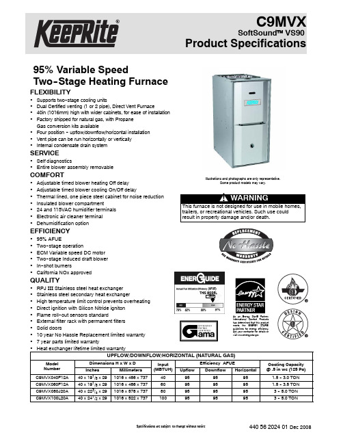
C9MVXSoftSound™VS90 Product Specifications95%Variable SpeedTwo--Stage Heating Furnace FLEXIBILITY•Supports two--stage cooling units•Dual Certified venting(1or2pipe),Direct Vent Furnace•40in(1016mm)high with wider cabinets,for ease of installation •Factory shipped for natural gas,with PropaneGas conversion kits available•Four position--upflow/downflow/horizontal installation •Vent pipe can be run horizontally or vertically•Internal condensate drain systemSERVICE•Self diagnostics•Entire blower assembly removableCOMFORT•Adjustable timed blower heating Off delay•Adjustable timed blower cooling On/Off delay•Thermal lined,one piece steel cabinet for noise reduction •Insulated blower compartment•24and115VAC humidifier terminals•Electronic air cleaner terminal•Dehumidification optionEFFICIENCY•95%AFUE•Two--stage operation•ECM Variable speed DC motor•Two--stage Induced draft blower•In--shot burners•California NOx approvedQUALITY•RPJ III Stainless steel heat exchanger•Stainless steel secondary heat exchanger•High temperature limit control prevents overheating •Direct ignition with Silicon Nitride igniton•Flame roll--out sensors standard•External filter rack with permanent filters•Solid doors•10year No Hassle Replacement limited warranty•7year parts limited warranty•Heat exchanger lifetime limited warrantyIllustrations and photographs are only representative.Some product models may vary.THIS MODEL95.0As an Energy Star®Partner,International Comfort Productshas determined that this productmeets the ENERGY STAR®guidelines for energy efficiency.Ask your contractor for details orvisit UPFLOW/DOWNFLOW/HORIZONTAL(NATURAL GAS)Model NumberDimensions H x W x D Input(MBTUH)Efficiency AFUE Cooling Capacity@.5in wc(125Pa) Inches Millimeters Upflow Downflow HorizontalC9MVX040F12A40x191/8x291016x486x73740959595 1.5--3.0TON C9MVX060F12A40x191/8x291016x486x73760959595 1.5--3.5TON C9MVX080J20A40x223/4x291016x578x737809595953--5.0TON C9MVX100L20A40x241/2x291016x522x7371009595953--5.0TONModel Number(*Denotes Brand(C,H,T)*9MVX040F12*9MVX060F12*9MVX080J20*9MVX100L20INPUT HIGH HEAT(BTUH)LOW HEAT(BTUH)40,00028,00060,00042,00080,00056,000100,00070,000HTG.CAPACITY HIGH HEAT(BTUH)LOW HEAT(BTUH)38,00027,00058,00041,00077,00054,00096,00067,000AFUE%(ICS)95959595TEMP.RISE RANGE High Heat(o F/o C)Low Heat(o F/o C)25--55/14--3125--55/14--3130--60/17--3330--60/17--3330--60/17--3330--60/17--3330--60/17--3330--60/17--33VENT SIZE^in(mm)2″(51)OD2″--3″(51--76)OD3″(76)OD3″(76)OD VOLTS/HZ/PH115/60/1115/60/1115/60/1115/60/1 RATING PLATE AMPS.9.511.414.614.6MIN./MAX.VOLTAGE104/127104/127104/127104/127 TRANSFORMER(V.A.)40404040GAS PIPE SIZE--inches(mm)1/2(12.7)1/2(12.7)1/2(12.7)1/2(12.7) COOLING CAP.(TONS) 3.0 3.5 5.0 5.0HIGH ALTITUDE PRESSURE SWITCH1177766117776711777681177769 FILTER SIZE--inches(mm)(qty)16X25X1(406x635x25)(1)16X25X1(406x635x25)(1)16X25X1(406x635x25)(2)16X25X1(406x635x25)(2) DIMENSIONS--WxDxH inches(mm)191/8x29x40(486x737x1016)191/8x29x40(486x737x1016)223/4x29x40(486x737x1016)241/2x29x40(622x737x1016) WEIGHT--Lbs(kg)150(68)168(76)187(85)203(92)^Vent size may vary depending on length,number of elbows,standard vent or direct vent.See Installation Instructions.*9M V X040F12A#Brand Identifier Engineering Rev. *=Brand Denotes minor changes Model Efficiency Marketing Digit 8=Non--Condensing,80+%Gas Furnace Denotes major change 9=Condensing,90+%Gas Furnace Cooling Airflow Installation Configuration08=800CFM UP=Upflow DN=Downflow12=1200CFM UH=Upflow/Horizontal DH=Downflow/Horizontal14=1400CFM16=1600CFM MP=Multiposition,Up/Down/Horizontal20=2000CFM MV=Multiposition,Variable Speed,Up/Down/Horizontal Cabinet Width Major Design Feature B=15.5″Wide 1=One(Single)Pipe N=Single Stage F=19.1″Wide 2=Two Pipe P=PVC Vent J=22.8″Wide D=1or2Pipe T=Two Stage L=24.5″Wide L=Low NOx V=Variable SpeedX=High EfficiencyInput(Nominal MBTUH) *Denotes Brand(C,H,T)Model Number Description Used With ModelsNAHA00601NG 1177457**Gas Conversion Kits(Two--Stage)--Propane to natural gas conversionkit.Allows field conversion to natural gas.*9MVXNAHA00601LP 1177456**Gas Conversion Kits(Two--Stage)--Natural gas to Propane conversionKit(includes low pressure switch).Allows field conversion to Propanegas.*9MVXNAHA001FF Filter Kits--External filter frame.16″x25″(406mm x635mm)Side Return(All Furnaces)Bottom Return(All“F”191/8″Furnaces under1600CFM)NAHA001FP External filter frame.16″x25″(406mm x635mm)Bulk Pack Kit--Qty10NAHA002FF Filter Kits--Bottom return filter frame kit20″x25″(All“J”223/4″Furnaces)NAHA002FP Bottom return filter frame kit20″x25″(508mm x635mm)Bulk Pack Kit--Qty10NAHA001TK Duct Standoff Filter Kit--To adapt20″x25″(508mm x635mm)filterfor single side return.Side Return(All single return applications with1600CFM or greater)Bottom Return(All“F”191/8″Furnaces under1600CFM)NAHA001NK612833**Condensate Neutralizer Kit--for condensing gas furnaces All*9MVX Furnaces if RequiredNAHH002SB Combustible Floor Subbase--Subbase Furnace ONLY:All191/4″widefurnace models*9MVX040/060NAHH003SB Combustible Floor Subbase--Subbase Furnace ONLY:All223/4″widefurnace models*9MVX080NAHH010SB Combustible Floor Subbase--Subbase Furnace ONLY:All241/2″widefurnace models*9MVX100NAHH005SB Subbase--Furnace w/191/4″cased coil*9MVX040/060Counterflow furnace w/191/4″cased coil NAHH006SB Subbase--Furnace w/223/4″cased coil*9MVX080Counterflow furnace w/223/4″cased coil NAHH009SB Subbase Furnace w/241/2″cased coil*9MVX100Counterflow furnace w/241/2″cased coil 1177766**High Altitude Pressure Switch Kit*9MVX0401177767**High Altitude Pressure Switch Kit*9MVX0601177768**High Altitude Pressure Switch Kit*9MVX0801177769**High Altitude Pressure Switch Kit*9MVX100NAHA001CV 1011129**3″(76.2mm)Concentric Vent Kit--allows single wall penetration for2pipe direct vent applications(90+)*9MVX080/100NAHA002CV2″(50.8mm)Concentric Vent Kit--allows single wall penetration for2pipe direct vent applications(90+)*9MVX040/060NAHA002WL To replace Warning Labels,Operating Instructions&Wiring Labels onBlower Door when needed*9MVX*Denotes Brand(C,H,T)**Fast part numberCooling Adjustment Heating Rise AdjustmentDIP Switch (OFF=0ON=1)High Cool@.50in wc(125Pa)Low Cool(80%of High Cool)**AdjustJumperSettingDIP Switch(OFF=0andON=1)High HeatRiseChange@0.20in wc(50Pa)Low HeatRiseChange atResultantStatic5&6CFM L/s CFM L/s3&4001244587995470+00--3--3 *001206569965455*NOM*0000 001126531901425--0044 011109523887419+0122 011032487826390NOM0166 01941444753355--011310 10901425721340+100--1 10828391662313NOM1033 10757357606286--1087 11705333564266+11--12--13 11633299506239NOM11--10--10 11556262445210--11--8--8 Airflow performance includes1”washable filter media.*Factory Setting**Adjust Jumper Setting(+,NOM,--)is applied to both Cooling and HeatingNote1:HP Mode Jumper provides a10%reduction in airflow when in Comfort position and a call for low or high cooling is present with the”O”line off.This feature is to provide lower airflow for running in HP Heating Mode if desirable.Note2:DEHUM mode(24VAC on DEHUM terminal)provides a20%airflow reduction during cooling calls.Note3:Low Heat ESP is a result of High Heat ESP(--is decrease in rise).Note4:High and low heat rise values are approximate air temperature change from return air temperature when at factory default settings.Table2AirflowDIP Switch (OFF=0/ON=1)Continuous Fan@ 0.10in wc(25Pa)ESP1&2CFM L/s*00592279011021482101346635111346635 *Factory SettingTable3SW2DIP Assignments DIP Switch Blower Parameter 1&2Cont Fan Adj3&4Heat Speed Adj5&6Cool Speed Adj7&8Cool On/Off DelayTable4Cooling Delay Options(SW2--7,8)ON DELAY OFF DELAYDIP SW2--7/8 (OFF=0/ON=1)Timed ON(sec)Airflow during ondelay Timer OFF(sec)Airflow during offdelay*005OFF90100% 015OFF0OFF103050%30100% 113050%18050% Airflow%is of High Cool airflow demand determined from SW2--5/6Table1Airflow resumes to100%after on delay time is completedAirflow stops(or switches to continuous fan speed)after off delay time is completed*Factory SettingMAX CFM’s for Factory Washable FiltersFilter Size(in/mm)CFM L/s14″X25″/356x635140066116″X25″/406x635160075520″X25″/508x635200094424″X25″/610x63525001180Max CFM based on600FPM(3.0M/s)NOTE:Disposable filters are typically rated at300FPM(1.5m/s). These filters only allow half the airflow when compared to600FPM (3.0M/s)filters.EXAMPLE(approx.):20in X25in@600FPM=2000CFM,@300FPM=1000CFM 508mm x635mm@3.0M/s=944L/s,@1.5M/s=472L/sCooling Airflow SettingsNOTE:Cooling Adjustment Heating Rise AdjustmentDIP Switch (OFF=0ON=1)High Cool@.50in wc(125Pa)Low Cool(80%of High Cool)**AdjustJumperSettingDIP Switch(OFF=0andON=1)High HeatRiseChange@0.20in wc(50Pa)Low HeatRiseChange atResultantStatic5&6CFM L/s CFM L/s3&40013776501102650+00--3--3 *001239585991585*NOM*0000 001097518878518--0033 011165550932550+0112 011044493835493NOM0144 01889420711420--0188 10966456773456+10--10 10848400678400NOM1022 10715337572337--1077 1174353599353+11--5--4 11650307520307NOM11--2--2 11523247418247--1111 Airflow performance includes1”washable filter media.*Factory Setting**Adjust Jumper Setting(+,NOM,--)is applied to both Cooling and HeatingNote1:HP Mode Jumper provides a10%reduction in airflow when in Comfort position and a call for low or high cooling is present with the”O”line off.This feature is to provide lower airflow for running in HP Heating Mode if desirable.Note2:DEHUM mode(24VAC on DEHUM terminal)provides a20%airflow reduction during cooling calls.Note3:Low Heat ESP is a result of High Heat ESP(--is decrease in rise).Note4:High and low heat rise values are approximate air temperature change from return air temperature when at factory default settings.Table2AirflowDIP Switch (OFF=0/ON=1)Continuous Fan@ 0.10in wc(25Pa)ESP1&2CFM L/s*0061247501109682210140310401114031040 *Factory SettingTable3SW2DIP Assignments DIP Switch Blower Parameter 1&2Cont Fan Adj3&4Heat Speed Adj5&6Cool Speed Adj7&8Cool On/Off DelayTable4Cooling Delay Options(SW2--7,8)ON DELAY OFF DELAYDIP SW2--7/8 (OFF=0/ON=1)Timed ON(sec)Airflow during ondelay Timer OFF(sec)Airflow during offdelay*005OFF90100% 015OFF0OFF103050%30100% 113050%18050% Airflow%is of High Cool airflow demand determined from SW2--5/6Table1Airflow resumes to100%after on delay time is completedAirflow stops(or switches to continuous fan speed)after off delay time is completed*Factory SettingMAX CFM’s for Factory Washable FiltersFilter Size(in/mm)CFM L/s14″X25″/356x635140066116″X25″/406x635160075520″X25″/508x635200094424″X25″/610x63525001180Max CFM based on600FPM(3.0M/s)NOTE:Disposable filters are typically rated at300FPM(1.5m/s). These filters only allow half the airflow when compared to600FPM (3.0M/s)filters.EXAMPLE(approx.):20in X25in@600FPM=2000CFM,@300FPM=1000CFM 508mm x635mm@3.0M/s=944L/s,@1.5M/s=472L/sCooling Airflow SettingsNOTE:Cooling Adjustment Heating Rise AdjustmentDIP Switch (OFF=0ON=1)High Cool@.50in wc(125Pa)Low Cool(80%of High Cool)**AdjustJumperSettingDIP Switch(OFF=0andON=1)High HeatRiseChange@0.20in wc(50Pa)Low HeatRiseChange atResultantStatic5&6CFM L/s CFM L/s3&4002146101317171013+00--3--3 *0020099481607948*NOM*0000 0018438701474870--0055 0117798401423840+0133 0116457761316776NOM0168 0114987071198707--011111 1014096651127665+1000 1012946111035611NOM1064 101147541918541--10109 111005474804474+11--5--6 11887419710419NOM11--2--2 11757357606357--1132 Airflow performance includes1”washable filter media.*Factory Setting**Adjust Jumper Setting(+,NOM,--)is applied to both Cooling and HeatingNote1:HP Mode Jumper provides a10%reduction in airflow when in Comfort position and a call for low or high cooling is present with the”O”line off.This feature is to provide lower airflow for running in HP Heating Mode if desirable.Note2:DEHUM mode(24VAC on DEHUM terminal)provides a20%airflow reduction during cooling calls.Note3:Low Heat ESP is a result of High Heat ESP(--is decrease in rise).Note4:High and low heat rise values are approximate air temperature change from return air temperature when at factory default settings.Table2AirflowDIP Switch (OFF=0/ON=1)Continuous Fan@ 0.10in wc(25Pa)ESP1&2CFM L/s*00100747501174282210220410401122041040 *Factory SettingTable3SW2DIP Assignments DIP Switch Blower Parameter 1&2Cont Fan Adj3&4Heat Speed Adj5&6Cool Speed Adj7&8Cool On/Off DelayTable4Cooling Delay Options(SW2--7,8)ON DELAY OFF DELAYDIP SW2--7/8 (OFF=0/ON=1)Timed ON(sec)Airflow during ondelay Timer OFF(sec)Airflow during offdelay*005OFF90100% 015OFF0OFF103050%30100% 113050%18050% Airflow%is of High Cool airflow demand determined from SW2--5/6Table1Airflow resumes to100%after on delay time is completedAirflow stops(or switches to continuous fan speed)after off delay time is completed*Factory SettingMAX CFM’s for Factory Washable FiltersFilter Size(in/mm)CFM L/s14″X25″/356x635140066116″X25″/406x635160075520″X25″/508x635200094424″X25″/610x63525001180Max CFM based on600FPM(3.0M/s)NOTE:Disposable filters are typically rated at300FPM(1.5m/s). These filters only allow half the airflow when compared to600FPM (3.0M/s)filters.EXAMPLE(approx.):20in X25in@600FPM=2000CFM,@300FPM=1000CFM 508mm x635mm@3.0M/s=944L/s,@1.5M/s=472L/sCooling Airflow SettingsNOTE:Cooling Adjustment Heating Rise AdjustmentDIP Switch (OFF=0ON=1)High Cool@.50in wc(125Pa)Low Cool(80%of High Cool)**AdjustJumperSettingDIP Switch(OFF=0andON=1)High HeatRiseChange@0.20in wc(50Pa)Low HeatRiseChange atResultantStatic5&6CFM L/s CFM L/s3&40021089951686995+00--3--3 *0019749321579932*NOM*0000 0018128551450855--0045 0117128081370808+0111 0115877491270749NOM0145 0114226711138671--01910 1013126191050619+10--2--1 101197565958565NOM1012 101056498845498--1057 11919434735434+11--5--6 11797376638376NOM11--3--3 11641303513303--1122 Airflow performance includes1”washable filter media.*Factory Setting**Adjust Jumper Setting(+,NOM,--)is applied to both Cooling and HeatingNote1:HP Mode Jumper provides a10%reduction in airflow when in Comfort position and a call for low or high cooling is present with the”O”line off.This feature is to provide lower airflow for running in HP Heating Mode if desirable.Note2:DEHUM mode(24VAC on DEHUM terminal)provides a20%airflow reduction during cooling calls.Note3:Low Heat ESP is a result of High Heat ESP(--is decrease in rise).Note4:High and low heat rise values are approximate air temperature change from return air temperature when at factory default settings.Table2AirflowDIP Switch (OFF=0/ON=1)Continuous Fan@ 0.10in wc(25Pa)ESP1&2CFM L/s*00103248701177883910217810281121781028 *Factory SettingTable3SW2DIP Assignments DIP Switch Blower Parameter 1&2Cont Fan Adj3&4Heat Speed Adj5&6Cool Speed Adj7&8Cool On/Off DelayTable4Cooling Delay Options(SW2--7,8)ON DELAY OFF DELAYDIP SW2--7/8 (OFF=0/ON=1)Timed ON(sec)Airflow during ondelay Timer OFF(sec)Airflow during offdelay*005OFF90100% 015OFF0OFF103050%30100% 113050%18050% Airflow%is of High Cool airflow demand determined from SW2--5/6Table1Airflow resumes to100%after on delay time is completedAirflow stops(or switches to continuous fan speed)after off delay time is completed*Factory SettingMAX CFM’s for Factory Washable FiltersFilter Size(in/mm)CFM L/s14″X25″/356x635140066116″X25″/406x635160075520″X25″/508x635200094424″X25″/610x63525001180Max CFM based on600FPM(3.0M/s)NOTE:Disposable filters are typically rated at300FPM(1.5m/s). These filters only allow half the airflow when compared to600FPM (3.0M/s)filters.EXAMPLE(approx.):20in X25in@600FPM=2000CFM,@300FPM=1000CFM 508mm x635mm@3.0M/s=944L/s,@1.5M/s=472L/sCirculation Air Blower Data-*9MVX100Cooling Airflow Settings18I nternational Comfort Products,LLCLewisburg,TN37091U.S.A.。
G90指令的讲解

运动轨迹:A-B-C-D,即切入-切
+X
2、圆锥面: G90 X(U)___ Z(W)___ R___ F___ ;
z
w
退刀点
循环起点
D 4R
A
3R
1R
u/2
其中:X、Z为切削终点绝对坐标; U、W为切削终点相对坐标; R为锥面切削时的半径差; R=(X切削起点- X切削终点)/2
Z-40.0 ; G00 X32.0 ;
Z5.0 ; G01 X17.0 F0.5;
Z-40.0 ; G00 X32.0 ;
Z5.0 ; G01 X14.0 F0.2 ;
Z0.0 ; X16.0 Z-1.0 ; Z-40.0 ; X27.0 ; X29.0 Z-41.0 ; Z-90.0 ; G00 X100.0 ; Z100.0 ; M30 ;
复习提问
G00、G01指令的编程格式是什么? 利用G00/G01指令编制红色轨迹的程序。
某中型零件制造企业,接到500 件刀杆的生产任务订单,要求三天内完 成生产。订单提供刀杆的零件图纸。作 为数控车床操作工,要根据刀杆的零件 图和工艺卡的要求进行首件试生产,并 检测加工精度,以便实现批量生产。
归纳总结
当编程起点不在圆锥面小端外圆轮廓上时,注意锥度起点和终点 半径差的计算
在对锥度进行粗、精加工时,虽然每次加工时R值都一样,但每 条语句中R值都不能省略,否则系统会按照圆柱面轮廓处理。
思考:
如图所示为棒料毛坯 (直径为Φ55)的加工 示意图,钻孔后的内孔 直径是Φ26,编写其加 工程序。
友情提醒
循环起点Z值设置在毛坯右端面前面处, 注意R值的计算问题
C
切削终点
2F
i
BROTHER MFC-8460N MFC-8860DN 打印机 说明书
i
目录
第一部分
1 概述信息
使用文档 ............................................................................................................... 文档中使用的符号和惯例 ................................................................................ 使用完整的使用说明书 .......................................................................................... 浏览文档 ......................................................................................................... 操作面板概述 ........................................................................................................ 状态指示灯显示 .............................................................................................. 2 2 2 2 5 8
ii
第二部分
5 发送传真
传真
28 28 28 28 29 29 29 30 30 31 31 31 33 33 34 34 35 35 35 36 36 36
greenlee 7904sb 7906sb 快速拔出 90
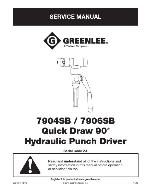
Register this product at 99947315 REV 3© 2016 Greenlee Textron Inc.11/167904SB / 7906SB Quick Draw 90®Hydraulic Punch DriverQuick Draw 90® Hydraulic Punch DriverGreenlee / A Textron Company4455 Boeing Dr. • Rockford, IL 61109-2988 USA • 815-397-70702SafetySafety is essential in the use and maintenance of Greenlee tools and equipment. This manual and any markings on the tool provide information for avoiding hazards and unsafe practices related to the use of this tool. Observe all of the safety information p rovided.Purpose of this ManualThis manual is intended to familiarize all personnel with the safe service procedures for the following Greenlee tool: 7904SB / 7906SB Serial Code ZA Keep this manual available to all personnel.Replacement manuals are available upon request at no charge at .Other PublicationsInstruction Manual: 99947307All specifications are nominal and may change as designimprovements occur. Greenlee Textron Inc. shall not be liable for damages resulting from misapplication or misuse of its products.Quick Draw 90 is a registered trademark of Greenlee Textron Inc.Loctite and 242 are registered trademarks of Loctite Corporation.KEEP THIS MANUALTable of ContentsSafety ............................................................................2Purpose of this Manual .................................................2Other Publications .........................................................2Important Safety Information .....................................3–4Maintenance ..................................................................5Troubleshooting .............................................................6Disassembly ..................................................................7Ball Seat Repair .............................................................7Reassembly ...................................................................8Inspection and Adjustments ..........................................9Illustration ....................................................................10Parts Lists ....................................................................11Draw Studs and Accessories .. (12)Quick Draw 90® Hydraulic Punch DriverGreenlee / A Textron Company4455 Boeing Dr. • Rockford, IL 61109-2988 USA • 815-397-70703IMPORTANT SAFETY INFORMATIONQuick Draw 90® Hydraulic Punch DriverGreenlee / A Textron Company4455 Boeing Dr. • Rockford, IL 61109-2988 USA • 815-397-70704IMPORTANT SAFETY INFORMATIONNote: Keep all decals clean and legible, and replace when necessary.Quick Draw 90® Hydraulic Punch DriverGreenlee / A Textron Company4455 Boeing Dr. • Rockford, IL 61109-2988 USA • 815-397-70705MaintenanceMaintenance and repairs should be performed in a dust-free area by qualified technicians.This unit requires minimum maintenance because it has a closed hydraulic system and all internal parts are lubricated by the hydraulic fluid. Lubricate lever pins lightly. Keep contaminants away from the ram and cyl-inder. Store with the lever down and hydraulic p ressure released.Adding Hydraulic Oil1. Place the driver in a vise in a vertical position withthe handles up. Unscrew the reservoir handle and remove the bladder plug. Open the release valve knob to assure the ram is fully extended.2. Fill the rubber bladder to the point of overflow withGreenlee hydraulic oil.3. Purge air from the system: Pump the lever handle several times to remove airfrom the pumping chamber. Close the release valve knob and pump the lever handle until the ram com-pletes its full travel. Repeat as necessary.Note: Open the release valve knob slowly so the ram extends slowly. Rapid return of oil and air may cause the oil to overflow the rubber bladder. If this procedure fails to remove air, remove thebladder plug and open the release valve knob. Place thumb over the plug hole in the bladder and squeeze the bladder while pumping the lever handle several times. Close the release valve knob and pump the lever handle until the ram completes its full travel. Repeat as necessary. If this procedure does not remove air, remove theplunger (24) and fill the plunger cavity with clean oil as described in the “Reassembly” section of this manual.4. Fill the rubber bladder to the point of overflow andreplace the bladder plug. Wipe the bladder clean of excess oil and reassemble the reservoir handle.Oil Leaks• Check for external oil leaks.• Check that the release valve knob and stem are closed tightly and seating properly.• Remove the reservoir handle and check for oil leaks around the rubber bladder and bladder plug.Ram Section Will Not Rotate1. Loosen and readjust the set screw (13).2. Hold the punch driver with the ram section down.3. Apply a small amount of penetrating oil to the cyl-inder (1) at the attachment point, and then work the ram section back and forth.4. Apply a small amount of SAE 30 oil to the cylindercollar next to the pump block.Quick Draw 90® Hydraulic Punch DriverGreenlee / A Textron Company4455 Boeing Dr. • Rockford, IL 61109-2988 USA • 815-397-70706TroubleshootingProblemProbable CauseProbable RemedyDoes not punch hole.Improper assembly or use of punch, die, or accessories.Refer to “Operation” and “Capacity and Draw Stud Selection Guide” inthe Instruction Manual.Low oil level.Refer to “Adding Hydraulic Oil” in the “Maintenance” section.Requires excessive lever force.Improper assembly or use of punch, die, or accessories.Refer to “Operation” and “Capacity and Draw Stud Selection Guide” inthe Instruction Manual.Material being punched is too thick or too hard.Refer to “Capacity and Draw Stud Selection Guide” in the Instruction Manual.Pump does not build p ressure.Air in system.Refer to step 3 of “Adding Hydraulic Oil” in the “Maintenance” section.Excessive number of strokes are required to punch hole.Inoperative intake check valve.Refer to “Intake Check Valve” inspection in the “Inspection and Adjustments” section.Inoperative discharge check valve.Refer to “Discharge Check Valve” inspection in the “Inspection and Adjustments” section.Leaking release valve.Refer to “Release Valve” inspection in the “Inspection and Adjustments” section.Damaged piston, piston extension, pump plunger seals, or mating surfaces.Refer to “Maintenance,” cylinder and pump block sections.Clogged filter.Clean or replace filter (40).Does not return piston.Weak or damaged return spring; excess oil in unit.Refer to “Ram Travel Inspection” in the “Inspection and Adjustments” section.External oil leaks.Damaged piston, piston extension, pump plunger seals, or mating surfaces.Refer to “Maintenance,” cylinder and pump block sections.Damaged release valve stem seal.Refer to “Release Valve” inspection in the “Inspection and Adjustments” section.Quick Draw 90® Hydraulic Punch DriverGreenlee / A Textron Company4455 Boeing Dr. • Rockford, IL 61109-2988 USA • 815-397-70707DisassemblyPump SectionNote: Separate ram section from pump section. Remove set screw (13). Unscrew ram section from pump section.1. Remove reservoir handle (21) and bladder plug (20);drain oil from the bladder (29).2. Remove O-ring (35) and the bladder (29). Removeretaining rings (37) from one end of both handle pins (30) and remove handle pins and handle (22).3. Grasp plunger (24) with pliers; pull and twist toremove. Loosen set screw (12) from release valve knob (27); remove knob. Unscrew release stem (28) to remove from pump block (2). Remove oil filter (40). Unscrew inlet check seat (23) and remove ball (32) and spring (31). Unscrew jam screw (26). Remove spring (39) and ball (6). Ram SectionNote: Refer to illustration on the next page.1. Thread an installation rod into the tapped holein ram (3). Place a flat washer and threadedhex nut on the installation rod. Tighten the nut until the spring retaining plate (4) is no longer applying force against the retaining rings (5).2. Remove the retaining rings (5) from the installationrod and remove the spring retaining plate (4) and compression spring (7).3. Screw a draw stud into end of ram (3); push the ramout of the cylinder (1).You have now disassembled the punch driver.T horoughly clean all parts and inspect the three ball seats (intake, discharge, and release stem) for nicks, scratches, or other damage.Ball Seat RepairRe-seatingMinor seat imperfections may be corrected byre-seating. Use a soft brass rod and hammer to tapthe ball against its seat.Re-drillingBadly worn or damaged seats may be reworked by re-drilling and then re-seating.The pump block is manufactured with seats of 118°, the standard drill point angle; use standard drills for re-drilling.• To re-drill the 7/32" ball seat for release stem (28): Use an “I” drill and a 9/64" diameter reamer.• To re-drill the 7/32" ball seat for the discharge check: Use an “I” drill and a 5/32" diameter reamer.• To re-drill the 3/16" ball seat for the intake check: Use a 1/4" drill and a 1/8" diameter reamer.When drilling, remove a minimum of material to obtainmaximum seat life. Re-seat the balls before reassembly.Discharge CheckIntake CheckStemQuick Draw 90® Hydraulic Punch DriverGreenlee / A Textron Company4455 Boeing Dr. • Rockford, IL 61109-2988 USA • 815-397-70708ReassemblyReassembly is done in reverse sequence of disassembly.Use repair kit 50383159 to replace all O-ring seals, balls, and springs.Ram Section1. Lightly coat ram (3) and cylinder (1) seals and bothbores of the cylinder with clean oil.2. Push ram completely into cylinder.3. Thread installation rod into tapped hole in theram and install compression spring (7). Placespring retaining plate (4) on top of spring (7) so thei nstallation rod passes through the 1/4" hole in the retaining plate.4. Place a flat washer and thread a hex nut on theinstallation rod. Tighten the nut until spring retaining plate slides past the retaining ring groove. Install the two retaining rings (5) 180° apart. Remove installation rod.Pump SectionFill plunger (24) bore with clean hydraulic oil. Coat O-ring seals on plunger with clean oil and reinsertthe pump block (2) with release valve knob (27) closed.Ram Section to Pump Section1. Install drive pin (25) to the pump block (2).Note: The drive pin must be installed to less than 0.100" high.2. Lightly coat the O-ring groove on the pump blockand O-ring (14) with clean oil. Assemble O-ring (14) and backup ring (15) to pump block (2).3. Apply a light coat of grease (Molycote G) to theexternal threads of pump block (2). Make sure the O-ring (14) and backup ring (15) are lightly coated with oil. Carefully slide the cylinder (1) onto the pump block.4. Thread the cylinder onto the pump block untilit bottoms. Back off the cylinder until set screw (13) can be installed and still allow nearly 360° of r otation.Note: Repeat step 4 if cylinder is backed off more than one revolution.5. Apply Loctite ® 242® or equivalent to set screw (13)and install until set screw bottoms. Then back out 1/8 to 1/4 turn.6. Fill unit with clean oil and purge air. Refer to “AddingHydraulic Oil” in the “Maintenance” section.Flat Washer and Nut Spring Retaining Plate (4)Retaining RingsCompression Spring (7)Cylinder (1)Ram (3)Installation Rod (steel)Quick Draw 90® Hydraulic Punch DriverGreenlee / A Textron Company4455 Boeing Dr. • Rockford, IL 61109-2988 USA • 815-397-70709Inspection and AdjustmentsAfter reassembly, check the following:Ram Travel Inspection Ram ExtendedWith the draw stud removed and release valve knob open, observe whether end of ram (3) is flush to 1/64" (0.396 mm) below the end of cylinder (1). If it is not, the bladder (29) contains too much oil.To remove excess oil:1. Remove reservoir handle (21) and bladder plug (20).2. Slowly open release valve knob (27); excess oilshould come out of the bladder and the ram should move to become flush to 1/64" (0.396 mm) below the end of the cylinder (1).3. If excess oil does not come out, replace thecompression spring (7).Ram RetractedMeasure ram travel distance (difference between ram completely extended and completely retracted). Distance is 0.830" (21.1 mm) to 0.930" (23.6 mm).Pump Section Inspection Intake Check ValveClose the release valve knob and operate handle (22) until ram (3) bottoms and handle resistance increases.• If the ram bottoms in 30 strokes or less, the inlet check valve (32 and 23) is operating properly.• More than 30 strokes indicates an inlet check leak. Re-seat, re-drill, or replace the inlet check seat (23).Discharge Check ValveIf the handle (22) returns to the raised position by itself, the discharge check valve is leaking. Re-seat or re-drill the discharge check seat and replace the compression spring (39).Install socket screw (26) to depth shown. If screw isbottomed out, ball cannot move and Quick Draw handle will not pump.Release ValvePump the handle until the ram bottoms. Gently apply and maintain additional force on handle (22). If thehandle remains solid, the ball (32) is operating properly. If the handle (22) goes down slowly, the release valve is leaking. Re-seat or re-drill the release stem seat and replace O-ring (33).Cylinder RotationInstall a 3/4" draw stud and a 2" conduit size punch and die to the punch driver. Hold the driver by the reservoir handle (21) so the draw stud is horizontal; the cylinder should not rotate from the combined weight of the draw stud, the punch, and the die. If rotation occurs, O-ring (14) may be worn.If binding or roughness occurs during cylinder rotation, check for lubrication or damage at threads closest to set screw (13); also check adjustment of set screw (13).10Greenlee / A Textron Company4455 Boeing Dr. • Rockford, IL 61109-2988 USA • 815-397-7070Quick Draw 90® Hydraulic Punch DriverGreenlee / A Textron Company 4455 Boeing Dr. • Rockford, IL 61109-2988 USA • 815-397-707011Parts ListKey Part No. Description Qty1 50369148 Cylinder, angle driver (1)2 50369172 Block, pump (1)3 50369040 Ram, right angle driver (1)4 50369156 Plate, spring retaining (1)5 90518098 Retaining ring, 1.75 Truarc internal (2)6 90504526 Ball, steel, .218 diameter (1)7 50339079 Spring, compression, 1.34 x 1.65 x 1.76 (1)8 90538471 Backup ring, spiral, 1.00 x 1.24 x .027 Teflon (1)9 90513169 O-ring, 1.50 x 1.75 x .125 nitrile (1)10 90538498 Backup ring, spiral, 1.50 x 1.74 x .027 Teflon (1)11 90513304 O-ring, 1.00 x 1.25 x .125 nitrile (1)12 90510321 Screw, set, #8–32 x .187 socket cup point (1)13 90508815 Screw, set, 1/4–28 x .250 socket (1)14 90508971 O-ring, 1.37 x 1.62 x .125 nitrile (1)15 90508963 Backup ring, spiral, 1.37 x 1.62 x .121 (1)16 50318780 Decal (1)17 52081520 Decal, identification (1)18 90511301 O-ring, 1.50 x 1.62 x .062 nitrile (1)19 50232584 Grip, .600 x 1.00 x 4.50 (1)20 50324888 Plug, bladder (1)21 50368893 Handle, reservoir (1)22 50368877 Handle, pump (1)23 50368907 Seat, inlet check (1)24 50377159 Plunger (1)25 90538633 Pin, drive, .218 x .312 (1)26 90513371 Screw, jam, 5/16–24 x .156 socket (1)27 50368869 Knob, release valve (1)28 50368931 Stem, release (1)29 50342690 Bladder, rubber (1)30 52065581 Pin, handle (see note 1) (2)31 50342878 Spring (1)32 90506782 Ball, steel, .187 diameter (2)33 90538544 O-ring, .250 x .375 x .062 (2)34 90504585 Pin, roll, .125 x .375 (1)35 90517415 O-ring, 1.31 x 1.56 x .125 nitrile (1)36 90542304 Backup ring, spiral, .265 x .052 Teflon (1)37 50428270 Retaining ring (see note 1) (2)39 90538455 Spring, compression, .152 x .180 x .380 (1)40 52059251 Filter, oil (1)44 50368940 Cap, reservoir handle ................................................................................1Note 1: 52065581 handle pin (30) and 50428270 retaining ring (37) should be purchased together, replacing all previous pin designs.Quick Draw 90® Hydraulic Punch Driver4455 Boeing Drive • Rockford, IL 61109-2988 • USA • 815-397-7070An ISO 9001 Company • Greenlee Textron Inc. is a subsidiary of Textron Inc.USA Tel: 800-435-0786 Fax: 800-451-2632Canada Tel: 800-435-0786 Fax: 800-524-2853International Tel: +1-815-397-7070 Fax: + Draw Studs and AccessoriesCat. No. Part No. Description Qty29451 50294512 Draw stud, 7/16" stainless steel (optional) (1)31872 50318721 Draw stud, 3/4–16 x 4.12 (1)1924AA 50332488 Spacer, .767 x 1.37 x .875 (1)1614SS 50300431 Screw, 3/8" short adapter ...............................................................1 33967 50339672 Adapter, stud, 3/8–24 x 3/4–16 . (1)。
- 1、下载文档前请自行甄别文档内容的完整性,平台不提供额外的编辑、内容补充、找答案等附加服务。
- 2、"仅部分预览"的文档,不可在线预览部分如存在完整性等问题,可反馈申请退款(可完整预览的文档不适用该条件!)。
- 3、如文档侵犯您的权益,请联系客服反馈,我们会尽快为您处理(人工客服工作时间:9:00-18:30)。
天津港储运股份有限公司董事会关于
收购天津港货运公司90%股权的公告
根据1996年8月12日召开的1995年度股东大会授权,1996年12月19日本公司第十三次董事会作出了《关于收购天津港储运公司90%股权的决议》并按有关法律、法规实施此项收购工作。
1997年3月31日,本公司第十五次董事会研究决定正式收购天津港务局所属的天津港货运公司90%股权,本公司与港务局签署了《天津港储运股份有限公司收购天津港务局所属天津港货运公司90%股权协议》,现将有关事项公告如下:
一、天津港货运公司概况
天津港货运公司是天津港务局所属的全资子公司,成立于1990年,现有职工110人,主要从事全国沿海船舶代理业务,其所属的全资附属企业:天津港货运中心,主要从事沿海进出口货物代理业务。
天津港货运公司,目前已开辟天津—赤湾、天津—厦门、天津—海口、天津—汕头等多条定线班轮,此外主与70多家船公及货物通达国内沿海各港口,1996年1至9月份,实现税后利润927万元。
天津港货运公司执行33%所得税税率。
根据天津中环会计师事务所中环评字(96)第40号《资产评估报告》和天津市国有资产管理局津国资工评(1997)56号文《关于对天津港务局所属天津港货运公司国有资产评估结果予以确认的批复》,以1996年9月30日为评估基准日的天津港货运公司资产帐面总值为
人民币2913.38万元、负债帐面总值为人民币2034.54万元、净资产帐面值为人民币878.85万元,资产评估总值为人民币4125.56万元、负债评估值为人民币2034.54万元、净资产评估值为2091.02万元。
二、收购标的及价格
1.本公司向天津港务局本次收购天津港货运公司90%股权,天津港货运公司将被改组为有限责任公司(本公司占90%股权、天津港务局占10%股权),成为本公司控股子公司。
2.本次收购以净资产值法为作价依据,根据资产评估基准日至《天津港储运股份有限公司收购天津港货运公司90%股权协议》签署之日止天津港货运公司的资产、经营情况的变化等因素,本公司以人民币2250万元作为本次收购天津港货运公司90%股权的成交价格。
三、本次收购的目的、意义
1、本次收购是实施本公司1995年度股东大会确定的“将公司业务重心由港口物资集疏运逐步转向集港口装卸、储运及配套服务的全方位多功能港口经营”战略目标的第一步。
通过本次收购,本公司的经营范围能迅速搏斗、业务重心有所调整,综合实力和市场竞争力进一步增强。
2、本次收购为本公司的资本经营、最大限度地发挥天津港的优势和参与天津港的建设积累了经验,同时本次收购实施后,通过将天津港货运公司组建为有限责任公司,建立现代饲料厂制度,促进企业的发展,为天津港务局盘活存量资产,确保国有资产的保值、增值作了积极的探索。
四、备查文件
1、天津中环会计师事务所中环评字(96)第40号《资产评估报告书》
2、天津市国有资产管理局津国资工作(1997)56号《关于对天津港务局所属天津港货运公司国有资产评估结果予以确认的批复》
3、《天津港储运股份有限公司收购天津港务局所属天津港货运公司的协议》
4、本公司1995年度股东大会决议
5、本公司第十三次董事会决议
6、本公司第十五次董事会决议
7、天津市国有资产管理局津国资(1997)43号《关于对天津港务局有偿转让天津港货运公司90%股权申请的批复》
天津港储运股份有限公司董事会
一九九七年四月二日。
