GprMax中文说明书
EMAX 压缩器杆头压缩机产品说明书

EMAX Compressor Piston reciprocating Warranty StatementIMPORTANT!! You must register your compressor:To register your warranty and find theextended warranty options go to . Details and options for ourextended warranty will be provided online once you enter the required information.EMAX Compressor makes the following Warranty guarantee:•Standard Warranty: That each compressor unit is free from defects in material, workmanship, and parts for 1 year from the date of delivery. This Standard Warranty includes 1 year ofwarranty labor from an authorized technician. EMAX compressor is not responsible fordowntime during warranty service. If downtime is necessary, it is at the owner’s discretion,obligation, and expense, to have a redundant compressor. Parts shipped for warranty repairsshall only include ground freight charges for the first 90 days of the warranty period, thereafter owner is responsible for all freight charges of parts shipped for warranty. Any and all expresssh ipping charges of warranty parts would be at the owner’s expense. Standard technicalassistance is provided at no charge during and after the standard warranty period.•Honda Engine carry’s a 3 year Limited warranty under all warranty Tiers*Standard warranty has no obligation to maintain warranty status, warranty will expire one year from date of delivery. Please see available options below to extend your warranty.•Extended Warranty: EMAX compressor will extend your standard 1-year warranty to full 5 years when you opt to register for the extended warranty plan that includes using our SMART OIL™ and follow ing all routine maintenance set forth. Parts shipped for warranty repairs shall only include ground freight charges for the first 90 days of the warranty period, thereafterowner is responsible for all freight charges of parts shipped for warranty. Any and all expressshipping charges of warranty parts would be at the owner’s expense. Standard technicalassistance is provided at no charge during and after the standard warranty period.Required maintenance Schedule to maintain warranty status➢All units are shipped with break-in oil and must be changed no less than 70 hours to insure gasket seating.➢After the 70 hours of break-in you must change the oil➢Thereafter Oil Should be changed every 6 months or 1000 hours whichever occurs first.➢Always maintain proper oil level in unit. If the unit runs out of oil due to neglect the warranty will be void.➢Use only EMAX approved oils in your compressor, or your warranty is void.**Extended Limited Lifetime Pump Warranty With participation in our SMART OIL™ extended auto ship program EMAX compressor will extend your warranty plan to **Limited LifetimeWarranty on the pressure lubricated pump. All other non-wear and tear components to 10years. SMART OIL™ not only extends the life of your compressor pump, it also can reduceoperating noise levels and can create further energy savings. Warranty repair parts under theLimited Lifetime warranty will not include any shipping charges beyond the Standard Warranty, therefore owner is responsible for all freight charges for warranty parts. This plan includes our advanced technical air support. Smart Tech Support provides you with the highest level oftechnical support. Smart Tech support is an interactive support team available to you at yourfingertips by just downloading a free app. The app provides free remote meetings, interactivetouch display, real live personal to assist.Limited Lifetime Warranty is not prorated and has no hour limits.**Limited Lifetime Warranty, non-prorated, no hour limits. In the case the product has been discontinued atany point the Limited lifetime Pump warranty will last five years past the discontinued date. Warrantor hasdiscretion to substitute parts with current model for the five-year duration*In order to maintain Limited Lifetime Warranty status, the owner must adhere to and purchase from EMAX Compressor the required maintenance items as scheduled below utilizing our Smart Whisper Blue Auto Ship program:Required maintenance Schedule to maintain warranty status➢All units are shipped with break-in oil and must be changed no less than 70 hours to insure gasket seating.➢After the 70 hours of break-in you must change the oil➢Thereafter Oil Should be changed every 6 months or 1000 hours whichever occurs first using only our Smart Whisper Blue Oil➢Always maintain proper oil level in unit. If the unit runs out of oil due to neglect the warranty will be void.➢Use only Smart Whisper Blue Oil and filters purchased from Emax Compressor in yourcompressor, or your warranty will be voided.➢Must be an active member of EMAX Compressor auto ship program•Warranty Shall not apply and Emax Compressor shall not be responsible nor liable for: ➢Routine service such as oil changes, filter replacements, gasket tightening to correct oil seepage or drive belt tightening and valve cleaning and are not covered under warranty.➢Consequential damages such as but not limited to cost of loss of business, product damage, or down time➢Acts of nature, over abuse, malicious destruction, improper maintenance, undersized equipment➢In the case the product has been discontinued at any point the *Limited lifetime warranty will last five years past the discontinue date. EMAX Compressor has discretion to substitute partswith current model for the five-year duration.➢Deviation from operating instructions or specifications➢Labor charges for repairs or maintenance made by person(s) other than an authorized, approved service technician or any labor after the 1-year Standard Warranty expires.➢Normal wear and tear parts included but not limited to valves (intake/suction, check, blowdown, thermo, pop off, unloader), and ball valves. Belts, shaft seals, load/unloader solenoids, sensors(temperature or pressure), Electrical contractors and relays, and any parts with a routinemaintenance scheduleWarranty shall be voided under the following conditions: Exposing electrical components to rain or water, or installing the unit in a hostile environment such as acid vapors or any caustic or abrasive matter that may be ingested into the pump, or installing the unit in an enclosed area where lack of cooling ventilation is present, such as in boiler or equipment rooms where the ambient air exceeds 100F.Further exclusions include failure to fully and completely follow the guidelines set forth in the manual. Of specific note is environments where fine dust is common, such as granite, marble or concrete plants, the compressor MUST be installed in a separate area with its own dedicated ventilation. FAILURE TO PROVIDE THIS DUST FREE OPERATING AREA VOIDS THE WARRANTY.Parts used for warranty purposes must be supplied by EMAX Compressor. Warranty work should be performed by an EMAX Compressor approved Technician. If any maintenance (other than routine maintenance) is performed by a non-approved Technician, written pre-approval must be obtained from EMAX Compressor, to prevent voiding this warranty. Failure to fully comply with this warranty and fully comply with the manual instructions will void this warranty.Warranties are non-transferableThe oil purchase and maintenance program are effective as of Nov. 2019。
Massimo GP7056E 雪扁平器操作手册说明书

OPERATOR’S MANUAL MASSIMOGP7056E Snow BlowerIMPORTANTREAD INSTRUCTIONS CAREFULLY BEFORE OPERATIONImportant Safety Operation Practices1WARNING: This symbol points out important safety instructions which, if not followed, could endanger the personal safety and/or property of yourself and others. Read and followinstructions in this manual before attempting to operate this machine. Failure to comply withthese instructions may result in personal injury.When you see this symbol, HEED ITS WARNING!DANGER: This machine was built to be operated according to the safety operation practices in this manual. As with any type of power equipment, carelessness or any error on the part of the operator can result in serious injury. This machine is capable of amputating hands and feet and throwing objects. Failure to observe the following safety instructions could result in seriousinjury or death.General Operation1.Carefully read the vehicle’s operator’s manuals and thisequipment’s operator’s manuals before a ttempting toassemble or operate the equipment.Keep both manuals in a safe place for future and regularreference, also for ordering replacement pa rt s.2.The vehicle is designed for off-road usage and should notbe operated on public highways. Understand and complywith all laws and regulations governing the use of off-highway vehicles in your area.3.The vehicle handles and maneuvers are differentfrom a normal passenger car. Sharp high-speed turnsand abrupt maneuvers can cause vehicle to roll overor go out of control. Slow down when turning andavoid abrupt maneuvers.4.Be familiar with all instructions and proper operationsbefore starting the vehicle.5.Do not let children operate the vehicle. Do not let adultsoperate the vehicle without proper instruction. Onlypersons who are well acquainted with these safetyoperation practices should be allowed to use theequipment.6.Watch for traffic when the vehicle is near roadways. Thisvehicle is not intended for use on any public r oad.7.No one should operate this equipment while intoxicatedor while taking medication which impairs the senses orreactions.8.Never carry more than one passenger. This vehicle isdesigned to carry the driver and one passenger only.No riders are allowed in cargo box or anywhere else onthis vehicle.9.Keep all body parts (i.e. head, arms, hands, legs, feet) insidethe vehicle when it is in motion.10.Always remain seated and keep both hands on the steeringwheel when driving the vehicle.11.12.13.14.15.16.17.18.19.20.21.Sit on the center of the seat and keep both feet withinthe foot platform perimeter. The foot platform maybecome slippery from snow or ice. Pay more attentionwhen mounting or dismounting the vehicle.Inspect the whole area around the vehicle beforemoving, especially the back side. Back up slowly. Alwayslook behind before and while backing to avoid a back-over accident. Keep bystanders out of area.Do not mount or leave the vehicle while it is in motionor in a ctual operation.Never leave the vehicle unattended with the key in theignition. After using, always turn the vehicle to the“Stop” position, set the parking brake and remove thekey.Check overhead clearances carefully before operatingunder h anging tree branches, wires, etc. or in any othersituation where the operator or passenger may be struckor pulled from the unit. Such negligence could result inserious injury.Engine must be stopped when cleaning, servicing,adjusting, repairing, or installing attachments on utilityvehicle.The vehicle and attachment should be stopped andinspected for damage after striking a foreign object.The damage should be repaired before restarting andoperating the equipment.Do not start and run vehicle in an inside area, unless it isadequately ventilated. Engine exhaust contains carbonmonoxide fumes, which is very poisonous and can causedeath.Always inspect the vehicle before using to make sure itis in safe operating condition.Operate blade only in daylight or in good artificial light.Always turn on the vehicle lights while operating in lowlight situations.Avoid overturns—Do not clear snow across the face ofslopes. Pay extreme attention when changing direction o n slopes. Do not attempt to clear steep slopes.222.No one should be allowed near the working area when theblade is being operated.23.Do not overload the vehicle capacity by attempting toclear snow too fast. Take the time to finish the job in asafe manner.24.Be careful to avoid catching the blade on stumps orother immovable objects.25.Never use the blade to tow another object.26.Pay extreme attention when operating theequipment close to ditches, fences or on hillsides.27.Be sure that the blade is fully raised and is instraight f orward position when it is in transport.28.When being close to buildings or passing throughnarrow areas, be sure there is enough clearance forthe blade.29.If situations occur which are not covered in thismanual, please contact your local Massimo dealer, orcall toll free 1-877- 881-6376 for further assistance.Slope OperationSlopes are a major factor related to loss of control and rollover accidents, which can result in severe injury or death. If a slope i s steeper than a 15° incline, do not operate this unit on the area. Exercise extreme caution while operating on slopes.Do:1.Travel straight up and down slopes, not across.2.Exercise extreme caution when changing direction onslopes.3.Travel slowly while on a slope. Always keep the forwardspeed limited when going down slopes.4.Keep all movement on the slopes slow and gradual. Avoidstarting or stopping on a s lope.Do Not:1.Do not travel near drop-offs, ditches or embankments. Thevehicle could suddenly turn over if a wheel is over the edgeof a cliff, ditch or if an edge caves in with the weight of theunit.2.Do not stop or start suddenly when going uphill or downhill.Be especially cautious when changing direction on slopes.3.Do not turn sideways to the hill. The vehicle may roll over. Ifyou must turn, go slow and do so carefully and gradually. ChildrenTragic accidents can occur if the operator is not alert tothe presence of children. Children are often attracted tothe vehicle. They do not understand the danger. Never assume that children will stay where you last saw them. Avoid accidents.a.Keep children out of the immediate area of thevehicle and in watchful care of a responsibleadult o ther than the operator.b.Be alert and turn the vehicle off if a child entersthe area.c.Before and while reversing, look behind and downfor small children.d.Never carry small children. They may fall off andbe seriously injured or interfere with safevehicle o peration.e.Pay extreme attention while approaching blindcorners, doorways, shrubs, trees or other objectsthat may block your vision of a child who may runinto the path of the vehicle.f.Remove the key when vehicle is unattended toprevent u nauthorized operation. Never allowchildren under 16 years old to operate this vehicle.g.16 - year old children and over should read andunderstand the operation instructions and safetyrules for the vehicle and equipment. They shouldbe trained and supervised by an adult, too.h.Do not let children ride in the cargo box, in thedriver’s or passenger’s lap or anywhere other thanthe passenger seat. Never give small children aride; not even in the passenger seat. They may falloff.3e e e e e a e e ea e a a e a a a a a e a eon the left and right sides of the housing respectively.: install the left pulling line (1) to the hole (4) of the handle as indicated in3. Install the left pulling line: install the left pulling line (1) to the hole (4) of the handle as indicated inthe diagramUTV experiencedfurther enhance y our6.Mount the engine cover:Unscrew the bolt above Air Filter, put engine cover on it.7. Mount the main chute: Use three M6x18 bolt (1) and three Nut M6 (2) to install the Main chute (4) to chute washer (3) on the snow bucket.8. Mount Side feet for Snow bucket : Use two M8x18 bolt (1) and two Nut M8(2) to install side feet (1) to left and right side of snow bucket.9. The Chute Rocker Assembly: Fit rotary pole to the pole seat beside the chute. Fit pole fixing bracket on the back of the handle.3. The auger control is located on the left handle. Squeeze the control grip against the handle to engage the augers and start snow throwing action. Release to stop.Notes:For parts, accessories or to find a dealer near you, visit:。
海南曼姆全系产品介绍说明书

Heinemann®GJ1P Series Circuit BreakersDESCRIPTIONOptional Low-Voltage Shunt for Current MeteringEaton Corporation’s Cutler-Hammer series of Heinemann GJ1P breakers offer high quality circuit protection for DC applications from 100 to 1200 Amperes.Their precisely tailored time delays and ability to interrupt high currents makes them ideally suited for critical applications. On overloads exceeding 1000 – 1400% of rating, there is no intentional time delay and the breaker interrupts currents of as much as 25,000 A at 65V DC.An optional shunt (25 or 50millivolt full scale) permits metering of current. Since the shunt output is low voltage,light-gauge wiring can be used from shunt to meter.Indication may be displayed inpercent, watts, safe/danger or other dial calibrations. In addition, the busbar is available in two versions:Standard Size and Reduced Size. Contact your Eaton Sales Representative for more information.Precision Current Equalization (PCE) Circuit BreakersGJ1P breakers rated 250 to1200 A are built in parallel construction. Conventional parallel pole breakers can experience uneven current distribution because of variations in internalresistances. This condition can result in nuisance tripping since the higher current in one parallel branch has the same effect as an overload on the sensing element in that branch. Proprietary Precision Current Equalization (PCE)circuit breakers, on the other hand, allow for differences in internal resistances byautomatically distributing the current equally through the parallel current sensing elements, minimizing the danger of nuisance tripping.The UL listed series GJ1P (UL489) models are available in a choice of fast, medium or slow response times to accurately match load conditions. They can be ordered in “series trip ”, “mid-trip ” and “switch only ”constructions and are available front- or back-mounted, front- or back-connected, with optional auxiliary switches for signaling.HYDRAULIC-MAGNETIC BENEFITSThe magnetic/hydraulic load-sensing and time delaymechanisms used in GJ1P breakers are insensitive to changes in ambient or enclosure temperature.Therefore, GJ1P circuitbreakers are suited for service conditions encountered in telecommunications,transportation, air conditioning and other outdoor or “heat-loaded ” equipment.SPECIFICATIONSStandard Current Ratings:100, 125, 150, 175, 200, 225,250, 300, 350, 400, 450, 500,600, 700, 800, 900, 1000,1100, 1200 A.Standard Maximum Voltages:160V DC up to 700A65V DC from 701 to 1200A Breakers will be labeled with standard maximum (UL) voltage unless otherwise specified.Special Current Ratings:Any integral rating between 100and 1200 A DC. Consult factory for ordering information and metering shunt restrictions.Interrupting Capacities:UL Listed:10,000 A @ 160V DC 25,000 A @ 65V DC Non-UL:14,000 A @ 160V DC.Operating Temperature Range:-40°C to +85°C.Approximate Weight:1-pole (100-225A) 1.13kg (2.5lbs)2-pole (250-400A) 2.27kg (5lbs)3-pole (450-700A) 3.40kg (7.5lbs)4-pole (701-800A) 4.54kg (10lbs)5-pole (801-1000A) 5.67kg (12.5lbs)6-pole (1001-1200A) 6.80kg (15lbs)Weight may vary based on shunt and busbar.APPROVALSUL Listing:GJ1P breakers are UL listed per UL489. For CSA certification,consult application engineering.Description . . . . . . . . . . . . . .2Specifications . . . . . . . . . . . .2Approvals . . . . . . . . . . . . . . .2Time Delay Characteristics . . .3Dimensions . . . . . . . . . . . .4-5How to Order . . . . . . . . . . .6-7Additional Products. . . . . . . . .8TABLE OF CONTENTS PageHEINEMANN ®CIRCUIT BREAKERSGJ1P Series Circuit Breakers(100-1200 Amperes DC)2Heinemann is a registered trademark of the Eaton Corporation, Commercial Controls Business Unit.100150.01.001.1110100100010,000200300400500600700800900100011001200125C u rv e 1C u rv e 2C u rv e 3Current – Percent of Ampere RatingT r i p T i m e – S e c o n d sDC CURVES100150.01.001.1110100100010,000200300400500600700800900100011001200125Current – Percent of Ampere RatingT r i p T i m e – S e c o n d sINSTANT DELAY DC CURVE PPERCENT OF RATED CURRENT VS. TRIP DELAY AT 25ºCTIME DELAYCHARACTERISTICSTime delay, in all models,is inversely proportional to the magnitude of the overload, adjusting automatically to limit transient power to the load. On overloads exceeding 1,000 –1,400%, the circuit breaker trips without any deliberately imposed delay.Curve 1.Standard time delayis furnished unlessanother optional delay is specified. It is thepreferred characteristic for use where the load is composed of both resistive and inductive components.Curve 2.Medium time delayis for general usein mixed (inductive and resistive) circuits where the breaker rating is matched to the current carrying capacity of the mains.Curve 3.Short time delaypermits a very brief delay period before tripping.Curve P .Non-time delay breakersare available forapplications which cannot tolerate even brief transient overloads.These breakers have no time delay mechanism other than that imposed by the coil self-inductance and the inertia of the mechanism.Tripping specificationsThe time delay curves depict breaker response time vs. percent of rated load with no preloading.The function is plotted at an ambient temperature of 77°F (25°C) with the breaker in a vertical or wall-mounted position.Series GJ1P circuitbreakers will carry 100%of rated load continuously.Both time delay and non-time delay breakers may trip between 101%and 125% of rated load,and must trip at 125%and above.3% (sec)Delay 100%125%200%400%600%800%1000%Delay Max.1no trip 1100150206 1.7.065Delay Min.1no trip 110224 1.1.01.008Delay Max.2no trip 110153.8.28.055Delay Min.2no trip 12 2.5.5.18.01.008Delay Max.3no trip 10.8.19.08.047.038Delay Min.3no trip.44.13.03.015.01.008STANDARD FRONT-CONNECTED CONSTRUCTIONWire Range #6 to 250 MCM74.59(2.938)76.20(3.000)Aux. Terminals, Male Type Molex 02-09-2101, Model 1190-T(See Illustrations for Combinations)Shunt Terminals, Female TypeMolex 02-09-1101, Model 1189-T37.69(1.484)42.84(1.687)0.99 (0.390)71.42(2.812)#10-32 Inserts (4 Places)38.10(1.500)19.05(0.750)19.05(0.750)6.35 ± 0.38(0.250 ± 0.156)6.35 ± 0.38(0.250 ± 0.156)Panel Mounting Hole Distance for #10-32LINELOAD 75.38(2.968)5.53(0.218)59.91(2.359)32.13(1.266)5.53(0.219)“D ” Type Terminals as Shown180.97(7.125)41.27(1.625)4.74(0.188)58.67(2.313)41.27(1.625)41.27(1.625)263.52(10.375)29.36(1.156)7.14(0.281)78.56(3.094)59.13(2.328)28°±5°32°±5°ONOFFSee Optional Terminal ConfigurationWire Range #6to 250 MCM41.27(1.625)36.49(1.437)38.10(1.500)100 – 22 A250 – 400Width dimensions are as follows:100 – 225 38.1 (1.5)250 – 400 A 76.2 (3.0)450 – 700 A 114.3 (4.5)701 – 800A 142.4 (6.0)801 – 1000A 190.5 (7.5)1001 – 1200A228.6 (9.0)28.95(1.141)46.40(1.828)22.22(0.875)Fastener Mounted ThisSide of Bus Plate,Terminals are Front-Connected and Unit is Rear-Mounted.Fastener Mounted This Side of Bus Plate, Terminalsare Back-Connected and Unit is Panel-Mounted.60.32(2.375)7.92(0.312)3/8-16UNC -2B (4 per Unit)38.10(1.500)225.43 (8.875)Center to CenterOptional Terminal ConfigurationsHEINEMANN ®CIRCUIT BREAKERSGJ1P Series Circuit BreakersDIMENSIONSDimensions are given here only as a preliminary guide to specifying. Final engineeringdrawings should be made from the latest Heinemann drawings. Contact Customer Service Center.Tolerance:±0.79 (0.031) except where noted. For metric threads, contact Customer Service Center.DIMENSIONS APPROXIMATE IN MM (INCHES)431.75(1.250) Min.41.65(1.641) Max.19.05(0.750)7.51(0.297)7.51(0.297)7.51(0.297)16.66(0.656)Typ.29.36(1.156)29.36(1.156)48.41(1.906)48.41(1.906)67.46(2.656)67.46(2.656)38.10(1.500)38.10(1.500)38.10(1.500)38.10(1.500)19.05(0.750)19.05(0.750)19.05(0.750)22.23(0.875) Min.321.31(12.65) Max.78.96(3.109)Min. Typ.5.15(0.203)Dia. Typ.C100 – 225 A Ratings 226 – 400 A Ratings401 – 700 150A RatingsBA106.75(4.203)Typ.C LC L C L FRONT MOUNTING PANEL AND SUPPORT BRACKET115.08(4.531)76.98(3.031)38.1(1.500)38.1(1.500)71.42(2.912)5.94(0.234)Ref.5.15(0.203)Typ. Dia.65.02(2.562)59.13(2.328)(3-Pole)3PoleC L C L C L Holes Required When Breaker Is Front-Mounted2Pole1PoleAB C (2-Pole)(1-Pole)38.88(1.531)19.43(0.765)Mounting kits containing clips, brackets and necessary hardware and instructions are available (consult factory).009-18234 100 – 225 A 1.5 (1-pole wide)009-18235 250 – 400 A 3 (2-pole wide)009-18232 450 – 700 A 4.5 (3-pole wide)For 701-1200A devices, contact your Eaton Sales Representative for mounting kit part numbers.See Step (2)See Step (5)BACK MOUNTING CIRCUIT BREAKERBack mounting circuit breaker mounting instructions 1. Position circuit breaker to support brackets.2. Place mounting bracket in recess on front top portion of circuit breaker.3. Install four (4) #10-32 by 3-1/4" long screws through holes in mounting bracket and support structure.4. Install lock washer and nut on each of the screws and tighten.5. Place mounting bracket on front lower portion of circuit breaker.6. Install two (2) #10-32 by 5/8" screws through holes in mounting bracket and support structure.7. Repeat step 4.5DIMENSIONS APPROXIMATE IN MM (INCHES)NOTE: Standard size busbar is shown above. For the reduced size busbar, contact your Eaton Sales Representative for mounting dimensions.Series PrefixGJ1PSwitch (No Coil)Series Trip w/SPDT Aux. SwitchSeries Trip Series Trip and Mid-Trip Series Trip, Mid-Trip and SPST Alarm SwitchTerminal Location Back FrontInternal Circuit Metering ShuntNo Shunts Metering Shunt Metering ShuntB HCodeLocationInternal CircuitCodeDescriptionShuntCode—25mV 50mVP M N0-2-3-98-99-Series Prefix GJ1PTerminal LocationBInternal Circuit3-Metering ShuntPAdd each appropriate Number or Letter …HEINEMANN ®CIRCUIT BREAKERSGJ1P Series Circuit BreakersHOW TO ORDER — Series GJ1PTo determine your Complete Catalog Number , you must start with appropriate Series Prefix and add the appropriate Code Letters and/or Numbers as in the example below:SELECTION TABLE61Multi-pole construction – Consult factory.An auxiliary switch, if supplied, will be located in the right pole space. If the auxiliary switch is supplied in a breaker which has a metering shunt, it will be single-pole single throw (SPST). The single-pole double throw (SPDT) auxiliary switch can be supplied only in a breaker without a metering shunt.2Cannot be used on breaker containing metering shunt.3Only for breakers rated in excess of 250 A. Breakers up to 250 A without meteringshunt are available as standard GJ1 type breakers. Please consult Series GJ catalog.MarketUL-489TerminalsSolderless Connector Bus Bar ConnectionStandard Current Ratings 1AmpereTrip Curve 1123P0 – 1200(Add 0 before amp rating if less than 1000A.Example: 0700)-01-02-03-0PDescriptionCodeDEDUStandardCodeCurveCodeComplete Catalog Number: GJ1PB3-PEDU0700-02Terminal ConfigurationEUS/European ApprovalDUStandard Current Ratings 10700Trip Curves 1-024Add 0 before amp rating if less than 1000. For example: a 700A rating would bedesignated as 0700.The width of the breaker is determined by the current rating:100 – 225 A 1.5” (1-pole wide)250 – 400 A 3” (2-pole wide)450 – 700 A 4.5” (3-pole wide)701 – 800A 6” (4-pole wide)801 – 1000A 7.5” (5-pole wide)1001 – 1200A 9” (6-pole wide)5See page 3 for time delay characteristics and trip curve information.7© 2001 Eaton Corporation All Rights Reserved Printed in USAForm No. BR5401SE0002A / CSS 65322June 2001Commercial ControlsFor the Widest Selection of Circuit Protection, from 0.01 to 1200 Amperes, Look to Eaton.。
耐克 psa 128max 产品说明书

產品說明書psa[128maxdigital audio playerPortable Sport Audio by Philips2目錄控制器與連接端子,附件––––––––––––––––––––––––––––––––––––––––4電腦系統最低需求–––––––––––––––––––––––––––––––––––––––––––––6一般說明–––––––––––––––––––––––––––––––––––––––––––––––––––––7電源供給–––––––––––––––––––––––––––––––––––––––––––––––––––8-9電源開/關, 播放和暫停2;節電模式––––––––––––––––––––––––––––––––––––––––––––––––––––10調整音量- / + 和eq (均衡器) 設定–––––––––––––––––––––––––––––11選擇一首不同曲目快速搜尋5, 6––––––––––––––––––––––––––––––––––––––––––––––12按鍵鎖––––––––––––––––––––––––––––––––––––––––––––––––––––12遙控器, 夾子磁石, 臂章機袋––––––––––––––––––––––––––––––––13-15psa 音樂管理安裝musicmatch jukebox軟件––––––––––––––––––––––––15-17安裝psa 驅動程式–––––––––––––––––––––––––––––––––––––––––18將psa 連接到你的電腦–––––––––––––––––––––––––––––––––––––19從cd 建立mp3 和windows media audio音樂檔案–––––––––––––––––––––––––––––––––––––––––––––––––20播放清單–––––––––––––––––––––––––––––––––––––––––––––––––21從你的電腦中下載音樂到psa –––––––––––––––––––––––––––––22-23更新MUSICMATCH 軟件,將你的音頻播放機升級––––––––––––––––––––––––––––––––––––––24有用的提示–––––––––––––––––––––––––––––––––––––––––––––––25-26技術規格–––––––––––––––––––––––––––––––––––––––––––––––––27-28目錄3警告請遵從下列指示使用本機,否則可能會危害你的健康。
GPRMAX2D知识点汇总
GprMax是爱丁堡大学的Antonis Giannopoulos于1996年推出来的一种基于时域有限差分(FDTD)算法和理想匹配层(PML)边界吸收条件的探地雷达正演数值模拟软件,用于探地雷达成像研究。
其中,GprMax2D是二维正演,GprMax3D为三维正演。
该软件可以在Windows、Linux和MacOS三个平台上使用。
本文主要针对Windows平台进行说明。
一、软件获得该软件为免费软件,可以去GprMax官网下载。
也可点此直接下载。
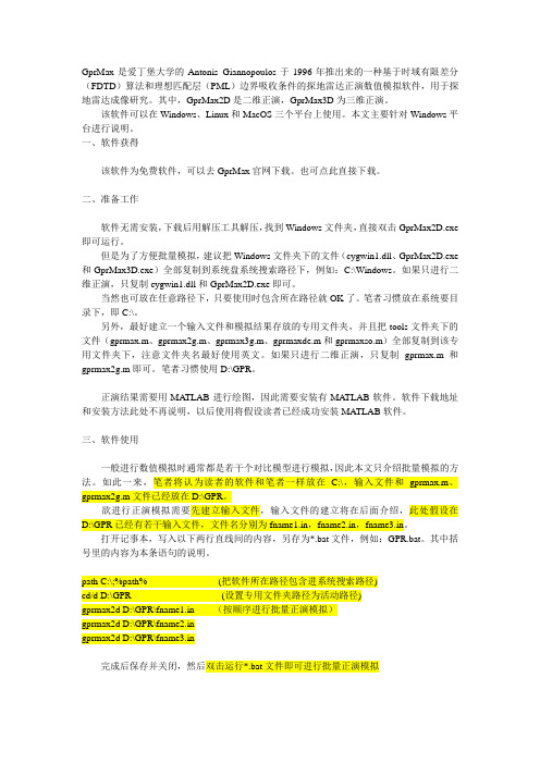
二、准备工作软件无需安装,下载后用解压工具解压,找到Windows文件夹,直接双击GprMax2D.exe 即可运行。
但是为了方便批量模拟,建议把Windows文件夹下的文件(cygwin1.dll、GprMax2D.exe 和GprMax3D.exe)全部复制到系统盘系统搜索路径下,例如:C:\Windows。
如果只进行二维正演,只复制cygwin1.dll和GprMax2D.exe即可。
当然也可放在任意路径下,只要使用时包含所在路径就OK了。
笔者习惯放在系统要目录下,即C:\。
另外,最好建立一个输入文件和模拟结果存放的专用文件夹,并且把tools文件夹下的文件(gprmax.m、gprmax2g.m、gprmax3g.m、gprmaxde.m和gprmaxso.m)全部复制到该专用文件夹下,注意文件夹名最好使用英文。
如果只进行二维正演,只复制gprmax.m和gprmax2g.m即可。
笔者习惯使用D:\GPR。
正演结果需要用MA TLAB进行绘图,因此需要安装有MA TLAB软件。
软件下载地址和安装方法此处不再说明,以后使用将假设读者已经成功安装MA TLAB软件。
三、软件使用一般进行数值模拟时通常都是若干个对比模型进行模拟,因此本文只介绍批量模拟的方法。
如此一来,笔者将认为读者的软件和笔者一样放在C:\,输入文件和gprmax.m、gprmax2g.m文件已经放在D:\GPR。
Bunn-O-Matic 单流量 GPR 热水器说明书

SINGLE ®GPR DBC-DVILLUSTRATED PARTS CATALOGDesigns, materials, weights, specifications, and dimensions for equipment or replacement partsare subject to change without notice.BUNN-O-MATIC CORPORATIONPOST OFFICE BOX 3227SPRINGFIELD, ILLINOIS 62708-3227PHONE: (217) 529-6601 FAX: (217) 529-664437981.0001A 7/12 ©2012 Bunn-O-Matic CorporationWITH SMART FUNNEL ®Dual Voltage ModelBUNN-O-MATIC COMMERCIAL PRODUCT WARRANTYBunn-O-Matic Corp. (“BUNN”) warrants equipment manufactured by it as follows:1) Airpots, thermal carafes, decanters, GPR servers, iced tea/coffee dispensers, MCP/MCA pod brewers thermal servers and Thermofresh servers (mechanical and digital)- 1 year parts and 1 year labor.2) All other equipment - 2 years parts and 1 year labor plus added warranties as specified below:a) Electronic circuit and/or control boards - parts and labor for 3 years.b) Compressors on refrigeration equipment - 5 years parts and 1 year labor.c) Grinding burrs on coffee grinding equipment to grind coffee to meet original factory screen sieve analysis - partsand labor for 4 years or 40,000 pounds of coffee, whichever comes first.These warranty periods run from the date of installation BUNN warrants that the equipment manufactured by it will be commercially free of defects in material and workmanship existing at the time of manufacture and appearing within the applicable warranty period. This warranty does not apply to any equipment, component or part that was not manufactured by BUNN or that, in BUNN’s judgment, has been affected by misuse, neglect, alteration, improper installation or operation, improper maintenance or repair, non periodic cleaning and descaling, equipment failures related to poor water quality, damage or casualty. In addition, the warranty does not apply to replacement of items subject to normal use including but not limited to user replaceable parts such as seals and gaskets. This warranty is conditioned on the Buyer 1) giving BUNN prompt notice of any claim to be made under this warranty by telephone at (217) 529-6601 or by writing to Post Office Box 3227, Springfield, Illinois 62708-3227; 2) if requested by BUNN, shipping the defective equipment prepaid to an authorized BUNN service location; and 3) receiving prior authorization from BUNN that the defective equipment is under warranty.THE FOREGOING WARRANTY IS EXCLUSIVE AND IS IN LIEU OF ANY OTHER WARRANTY, WRITTEN OR ORAL, EX-PRESS OR IMPLIED, INCLUDING, BUT NOT LIMITED TO, ANY IMPLIED WARRANTY OF EITHER MERCHANTABILITY OR FITNESS FOR A PARTICULAR PURPOSE. The agents, dealers or employees of BUNN are not authorized to make modifications to this warranty or to make additional warranties that are binding on BUNN. Accordingly, statements by such individuals, whether oral or written, do not constitute warranties and should not be relied upon.If BUNN determines in its sole discretion that the equipment does not conform to the warranty, BUNN, at its exclusive op-tion while the equipment is under warranty, shall either 1) provide at no charge replacement parts and/or labor (during the applicable parts and labor warranty periods specified above) to repair the defective components, provided that this repair is done by a BUNN Authorized Service Representative; or 2) shall replace the equipment or refund the purchase price for the equipment.THE BUYER’S REMEDY AGAINST BUNN FOR THE BREACH OF ANY OBLIGATION ARISING OUT OF THE SALE OF THIS EQUIPMENT, WHETHER DERIVED FROM WARRANTY OR OTHERWISE, SHALL BE LIMITED, AT BUNN’S SOLE OPTION AS SPECIFIED HEREIN, TO REPAIR, REPLACEMENT OR REFUND.In no event shall BUNN be liable for any other damage or loss, including, but not limited to, lost profits, lost sales, loss of use of equipment, claims of Buyer’s customers, cost of capital, cost of down time, cost of substitute equipment, facilities or services, or any other special, incidental or consequential damages.392, AutoPOD, AXIOM, BrewLOGIC, BrewMETER, Brew Better Not Bitter, BrewWISE, BrewWIZARD, BUNN Espress, BUNN Family Gourmet, BUNN Gourmet, BUNN Pour-O-Matic, BUNN, BUNN with the stylized red line, BUNNlink, Bunn-OMatic, Bunn-O-Matic, BUNNserve, BUNNSERVE with the stylized wrench design, Cool Froth, DBC, Dr. Brew stylized Dr. design, Dual, Easy Pour, EasyClear, EasyGard, FlavorGard, Gourmet Ice, Gourmet Juice, High Intensity, iMIX, Infusion Series, In-tellisteam, My Café, Phase Brew, PowerLogic, Quality Beverage Equipment Worldwide, Respect Earth, Respect Earth with the stylized leaf and coffee cherry design, Safety-Fresh, , Scale-Pro, Silver Series, Single, Smart Funnel, Smart Hopper, SmartWAVE, Soft Heat, SplashGard, The Mark of Quality in Beverage Equipment Worldwide, ThermoFresh, Titan, trifecta, Velocity Brew, A Partner You Can Count On, Air Brew, Air Infusion, Beverage Bar Creator, Beverage Profit Calculator, Brew better, not bitter., BUNNSource, Coffee At Its Best, Cyclonic Heating System, Daypart, Digital Brewer Control, Nothing Brews Like a BUNN, Pouring Profits, Signature Series, Tea At Its Best, The Horizontal Red Line, Ultra are either trademarks or registered trademarks of Bunn-O-Matic Corporation.237981.1 030912TABLE OF CONTENTS3Base - Trunk - Hood - Covers & Panels .......................................................................................................................................4 Dispense Valve and Sprayhead ..................................................................................................................................................18 Electrical Controls .....................................................................................................................................................................22 Faucet ........................................................................................................................................................................................20 Funnel........................................................................................................................................................................................26 Inlet Valve & Lines .....................................................................................................................................................................14 Numerical Index ........................................................................................................................................................................28 Strainer/Flow Control - Solenoid & Lines ..................................................................................................................................12 Tank and Mounting Brackets .....................................................................................................................................................10 Tank Heater & Overflow Protection Devices ................................................................................................................................8 Warmer Assemblies ..................................................................................................................................................................24 Water By-Pass (16)37981.1 070312437981.1 070312ITEMPART NO.QTY.DESCRIPTION5* Indicates the part number listed is for reference only. See DESCRIPTION for possible service replacement.1 25766.0001 1 Cover W/Decals, Top (Includes items2 & 3)02336.00001Screw, Truss Head #4 - 40 x .375"2 25151.0000 1 Shield, Insulator3 37881.0000 1 Decal, Warning - “No Serviceable Parts”4 00916.0000 1 Clip, J-Type #4 - 40536404.1005 1 Hood W/Decals (Includes item 6)02308.00007Screw, Pan Head #8 - 32 x .375"6 29973.0003 1 Membrane Switch 737426.1000 1Trunk W/Decals (17.75") 37426.1001 1 Trunk W/Decals (16.0")8 00656.0001 1 Decal, Comply to Plumbing Code 9 00986.0000 1 Decal, Warning - Electrical10 27744.1005 1 Panel W/Decals, 120/240V (17.66") (Includes items 11, 12, 29 & 30) 22987.1000 1 Panel W/Decals, 120/240V (15.92") (Includes items 11, 12, 29 & 30) 01382.0003 8 Screw, Truss Head Locking #6 - 32 x .375" 11 32043.0003 1 Schematic, Electrical 120/240V 12 00658.0000 1 Decal, Caution - Decanter/Funnel13 21511.1004 1 Warmer Panel Assy W/Decals (Includes items 14 & 15) 01311.0000 4 Screw, Truss Head SST #8 - 32 x .25" 14 12364.0000 1 Decal, Caution-Warmers Are Hot 15 02324.0000 2 Nut, Acorn #8 - 3216 28592.1004 1 Base Housing W/Decals, 120/240V (Includes item 17) 28592.0008 1 Base Housing, 120/240V 02308.0000 7 Screw, Pan Head #8 - 32 x .375" 17 20201.5600 1 Decal, Warning - Hot Water18 22979.0003 1 Cover, Bottom 120/240V22979.0004 1 Cover, Bottom 120/240V (Models with Main Power Switch) 22979.0007 1 Cover, Bottom 120/240V (Models with Main Power Switch)02308.0000 12 Screw, Pan Head #8 - 32 x .375" 19 26528.0000 4 Leg, 4.0" Plastic 20 03996.0000 4 Pad, Anti Skid2134020.0000 1 Plate, Decal Mounting (Models without Main Power Switch) 02308.0000 2 Screw, Pan Head #8 - 32 x .375" 22 32649.0000 1 Plate, Cover 00970.0000 2 Nut, Keps #8 - 32 23 00619.0007 1 Plug, .50" Dia.2400985.00001Decal, Individual Circuit InfoBASE - TRUNK - HOOD - COVERS & PANELSSee item 25(Continued)Includes items 8, 9 & 2437981.1 070312637981.1 070312ITEMPART NO.QTY.DESCRIPTION7* Indicates the part number listed is for reference only. See DESCRIPTION for possible service replacement.25 13255.0003 - Leg Kit (Includes 4 each of items 19 & 20) (Not Illustrated) 26 21104.0003 2 Server Stop, Bolt-On (Used in Product # 36100.0000) 21104.0007 2 Server Stop, Bolt-On (Used in Product # 36100.0010) 01347.0000 4 Screw, #6 - 32 x .38" 27 36398.0000 1 Hole Plug, DB-9 (Early models)28 03011.0000 2 Plug, Vent BLK 1.0" Dia. (Early models only) 29 29710.0012 1 Decal, Optional Field Wiring30 37881.0000 1 Decal, Warning - “No Serviceable Parts” 31 37766.0000 1 Cover, Access 02308.0000 2 Screw, Pan Head #8 - 32 x .375"3239803.00001Decal, Main Switch (Models with Main Power Switch only)BASE - TRUNK - HOOD - COVERS & PANELSUsed in Product # 36100.0000 only37981.1 070312837981.1 070312ITEMPART NO.QTY.DESCRIPTION9* Indicates the part number listed is for reference only. See DESCRIPTION for possible service replacement.1 23717.0003 1 Thermostat, Limit 00908.00002 Nut, Hex #8 - 32 2 02536.0000 4 Grommet, Probe (1 less used on brewers with Copper Overflow Cup)3 20936.1000 1 Probe Kit (Includes items 4, 5 & 6)4 01501.0000 1 Washer .164" I.D. x .375" O.D.5 20203.0100 1 Lockwasher, Internal Tooth #86 00908.0000 1 Nut, Hex #8 - 327 20922.1001 1 Tank Heater 1650W @ 120V (Includes Item 8) 20922.1004 1 Tank Heater 3235W @ 120V (Includes Item 8) 00908.0000 4 Nut, Hex #8 - 32 8 12398.0002 1 Gasket, Tank Heater 9 26622.0001 1 Tube Assy, Vent 10 37844.0000 1 Bracket, Vent Tube11 03803.0000 1 Switch Assy, Liquid Level, 120/240V (Includes Items 12, 13 & 14) 04797.0000 1 Washer, Celcon .520" I.D. x 1.0" O.D. 00946.0000 1 Nut, Hex .125" FPT 12 03633.0000 2 Gasket, Float Switch (Only 1 used in this application) 13 - - - - - - - - 3 Washer, Adjusting (DO NOT USE IN THIS APPLICATION) 14 03807.0000 1 Clip, Spring15 22728.0000 1 Overflow Cup Assy Copper (Also replaces aluminum cup) 41259.1003 1 Kit, Overflow Cup (Aluminum) (Includes items 2,18, 20 & 21) 00971.0000 2 Nut, Keps #10-32 16 12422.0000 2 Clamp, Hose .47"/.54" I.D.17 28526.0009* 1 Tube, Silicone .313" I.D. x 24" (Order Item 27) (Cut As Required) 18 04797.0000 1 Washer, Celcon .520” I.D. x 1.0” O.D. 19 00946.0000 1 Nut, Hex .125” FPT 20 41280.0001 1 Elbow,.375” Multi Barb 21 41266.0000 1 Film, Insulating22 12565.0011 1 Triac Assy, 40 Amp (120/240V) 02328.0003 1 Screw, Pan Head #6 - 32 x .312" 01520.0000 1 Lockwasher #6 23 20541.0001 1 Heat Sink, Aluminum24 M2522.1000 - Heat Sink Compound (Not Illustrated) 25 21801.0002 1 Tube, .375" O.D. x 1.50" LG 26 02434.0013* 1 U-Channel 1.0" (Order item 28) 27 28526.1000 - Tube, Silicone .313" I.D. x 12.0" 28526.1001 - Tube, Silicone .313" I.D. x 36.0" 28526.1002 - Tube, Silicone .313" I.D. x 60.0"28526.1003 - Tube, Silicone .313" I.D. x 120.0" 2802434.1000-U-Channel 18.0" (Use as required)TANK HEATER & OVERFLOW PROTECTION DEVICESNot illustrated37981.1 0703121037981.1 070312TANK AND MOUNTING BRACKETSITEM PART NO. QTY. DESCRIPTION1 28909.0000 1 Bracket, Tank Support (Top)02308.0000 1 Screw, Pan Head #8 - 32 x .375"00908.0000 2 Nut, Hex #8 - 322 22976.0003 1 Lid,Tank00908.0000 10 Nut, Hex #8 - 32TankG asket,3 22978.0000 14 22960.1008 1 Tank Assy (Includes Item 6)5 37517.0000 1 Bracket, Tank Mounting (Bottom) (Used in Product # 36100.0000)37541.0000 1 Bracket, Tank Mounting (Bottom) (Used in Product # 36100.0010)00971.0000 2 Nut, Keps #10 - 3202308.0000 4 Screw, Pan Head #8 - 32 x .375"6 - - - - - - - - 1 Bracket, Vent Tube (See TANK HEATER & OVERFLOW PROTECTION)STRAINER, SOLENOID & LINES ITEM PART NO. QTY. DESCRIPTION1 20937.0004 1 Tube, Tank Fill2 36089.0000 1 Tube, Assembly, Solenoid to Tank3 35094.0001 1 Solenoid Valve 120V4 36088.0002 1 Solenoid Valve Assy, 120V (Includes Items 3 & 5)01315.0000 2 Screw, Truss Head #8-32 x .375"5 34768.0001 2 Elbow, .38" Male Flare x .37"6 37892.0000 1 Tube Assy, Bulkhead Refill Tube .38" O.D. Rear7 02536.0000 1 Grommet, .375" I.D.8 12757.0000 1 Nut, Hex .625" - 18 Brass9 01514.0000 1 Lockwasher, Internal Tooth .625" I.D.10 12756.0000 1 Bulkhead Fitting .38" Flare11 37761.0000 1 90° Swivel Elbow12 00976.0000 1 Cap Nut, .375" Flare-4513 37127.0001 1 Bracket, Solenoid Mounting02308.0000 2 Screw, Pan Head #8-32 x .375”01522.0000 2 Washer, Flat .203” ID x .50” OD14 29421.0000 1 Clamp, Hose-Worm Drive .625”/.75”15 32591.1002 1 Tube, Silicone .50" I.D. x 36" LG16 11630.0001 1 Clamp, Tubing Shut Off .75" O.D.17 35086.0000 1 Plug, .50" I.D. Hose18 12422.0009 1 Clamp, Hose .71"/.80" I.D.19 32359.0000 2 Gasket, .375" Flare CopperINLET VALVE AND LINEITEM PART NO. QTY. DESCRIPTION1 02536.0000 1 Grommet, Fill Tube2 20937.0004 1 Tube, Tank Fill3 32359.0000 1 Gasket, .375" Flare Copper4 12418.0001 1 Fitting, Swivel .375" Barb5 12422.0001 2 Clamp, Hose .59"/.66" I.D6 20976.0000* 1 Tube, Silicone .375" I.D. x .625" O.D. x 30.0" (Order item 11)7 36378.0001 1 Check Valve (Installed in item 6)8 36233.1000 1 Valve, Water Inlet (Refer to item 12)32283.0000 2 Screw, Pan Head M4 x 6MM9 37297.0001 1 Elbow, .25" FLR x .75" FTHR10 41640.0000 1 Gasket, .75" Hose Fitting11 20976.1001 - Tube .375" ID x .625" OD x 36.0" (Use as required)20976.1002 - Tube .375" ID x .625" OD x 120.0" (Use as required)12 43644.0000 - Kit, Valve Rebuild)ITEMPART NO.QTY.DESCRIPTION1 32591.0014* 1 Tube, Silicone .50" I.D. x 3.60" (Order item 8) (Cut As Required)2 12422.0001 1 Clamp, Hose .59"/.66" I.D.3 12422.0005 2 Clamp, Hose .62"/.71" I.D.4 12422.0009 1 Clamp, Hose .71"/.80" I.D.5 27370.0003 1 Valve Assy, By-Pass 120/240V 00970.0000 2 Nut, Keps #8 - 32620976.0064*1Tube, Silicone .38" I.D. x .62" O.D. x 4.50" (Order item 9) (Cut As Required)7 32648.0000 1 Elbow Assy 832591.1001 - Tube, Silicone .50" I.D. x 12.0" 32591.1002 - Tube, Silicone .375" I.D. x 36.0"9 20976.1000 1 Tube, Silicone .38" I.D. x .62" O.D. x 12.0" 20976.1001 1 Tube, Silicone .38" I.D. x .62" O.D. x 36.0"20976.10021Tube, Silicone .38" I.D. x .62" O.D. x 120.0"WATER BY-PASSNot illustratedITEMPART NO.QTY.DESCRIPTIONDISPENSE VALVE & SPRAYHEAD1 26846.00002 Valve Assy, Sprayhead (Includes Items 2 thru 8) 2 23254.0000 4 Screw, #8 - 32322305.00001Coil Assy, Dispensing Valve4 23256.0000 1 Spacer Plate5 - - - - - - - - 1 Spring (Not available order item 18) 6- - - - - - - -1Plunger (Not available order item 18)7 23255.0000 1 Diaphragm 8 - - - - - - - - 1 Body (Not available order item 1)9 35052.0000* 1 Tube, Silicone .75" I.D. x 6.25" LG (Order item 17) (Cut as required) 10 12422.0008 2 Clamp, Hose Snap-Type.93"/1.1" I.D. 11 34956.0000 1 Fitting, .250" NPTF Hose .750" NPS 12 01075.0000 1 Nut, Hex .438" - 20 13 34868.0000 1 Seal, Sprayhead 14 35070.0001 1 Sprayhead Back 15 34867.0000 1 Sprayhead16 01082.0002 1 Sprayhead (6-098) (Used in Product # 36100.0010) 17 35052.1000 1 Tube, Silicone .75" I.D. x 1.0" O.D. x 12.0"18 11517.0008 - Repair Kit, Bypass & Dispense Valve(Includes one each of spring, plunger and diaphragm) 1935308.1004-Sprayhead Assy (Includes one each of items 13, 14 & 15)(Used in Product # 36100.0000) Refer to Item 19Not illustratedITEMPART NO.QTY.DESCRIPTION21* Indicates the part number listed is for reference only. See DESCRIPTION for possible service replacement.FAUCET129075.00001Faucet Assy (Includes Items 2 Thru 9)2 02861.0000 1 Handle, Faucet3 02854.0000 1 Bonnet, Faucet4 02595.0000 1 Spring, Faucet 502766.00001Seat Cup, Faucet6 02856.0002 1 Body, Faucet7 13054.0000 1 Stem, Faucet8 02858.0000 1 Pin, Spring .125" Dia. x .50"9 02594.0000 1 Faucet Stem W/Pin (Includes Items 7 & 8)10 20976.0065* 1 Tube, Silicone .38" I.D. x .62" O.D. x 12" (Order Item 16) (Cut As Required) 11 12422.0001 2 Clamp, Hose .59" x .66" I.D. 12 29264.0000 1 Nut, Faucet Retaining 13 01544.0000 1 Washer, .50" I.D. x .75" O.D.14 20976.0036* 1 Tube, Silicone .38" I.D. x .62" O.D. x 36" (Order Item 16) (Optional Lower Faucet)(Cut As Required)15 41184.0000 1 Washer, .57" I.D. x .72" O.D. x .048" (Late models) 16 20976.1000 1 Tube, Silicone .38" I.D. x .62" O.D. x 12.0" 20976.1001 1 Tube, Silicone .38" I.D. x .62" O.D. x 36.0" 20976.1002 1 Tube, Silicone .38" I.D. x .62" O.D. x 120.0" 17 28706.0002 - Faucet Kit (Includes Items 2, 4, 5, 7 & 8) 18M2517.0000-Sealant, Pipe 6 ml.Not Illustrated37981.1 0703122237981.1 070312ITEMPART NO.QTY.DESCRIPTION23* Indicates the part number listed is for reference only. See DESCRIPTION for possible service replacement.1 29969.1014 1 Circuit Board, Main control (Used in Product # 36100.0000) 29969.1000 1 Circuit Board, Main control (Used in Product # 36100.0010) 00973.00002 Nut, Keps #6 - 32 2 01533.0010 2 Spacer (Early models)3 29970.0000 1 Mount, Circuit Board (Early models) 40726.0000 1 Mount, Circuit Board (Late models) 00973.0000 2 Nut, Keps #6 - 324 - - - - - - - - 1 Sensing Coil WO/Leads (Early models) (Not available order item 23) 32572.1001 1 Sensing Coil W/Violet Leads (Includes plug below) (Late models) 20621.0000 1 Plug, hole .203" Dia. (Not illustrated)5 32573.0000 1 Cover, Sensing Coil 01382.0007 2 Screw, Truss Head #6 - 32 x .38" 6 01309.0000 1 Ground Screw W/Terminal Washer #10 - 32 x .50"7 23004.0000 1 Bracket, Terminal Block Mounting39248.0001 1 Bracket, Terminal Block Mounting (Models with Main Power Switch) 02308.0000 2 Screw, Pan Head #8 - 32 x .38" 8 07038.0000 1 Terminal Block, 3 Pole (BLK/RED/WHI) 01106.0001 1 Terminal Block, 2 Pole (BLK/RED)01317.00002Screw, Truss Head #8 - 32 x .50"9 01590.0000 1 Connector, Cable 10 12570.0000 1 Grommet, Temperature Sensor 11 29327.0001 1 Probe, Temperature & Dry Plug 12 32018.0000 1 Bumper (Early models)1337754.1000 1 Bracket W Decal, Switch (Includes item 15) 00970.0000 2 Nut, Keps #8 - 32 14 23522.0001 1 Switch, Toggle 15 34056.0001 1 Decal, Switch16 04831.0000 1 Clamp, SST Rubber Coating (Used To Hold Electrical Wires In Place) 17 38894.0001 1 Switch, Main Power (Not used on all models) 01308.0002 2 Screw, Truss Head #6-32 x .25" (Switch Mounting) 01327.0000 4 Screw, Pan Head #10-32 x .375"01512.0000 4 Lockwasher, External Tooth #10 1800824.00021Decal, GroundNote: The following parts are not illustrated 19 32647.0000 1 Wiring Harness, Main 20 37917.0000 1 Wiring Harness, Voltage Select 21 37859.0002 1 Wiring Harness, Main Power Switch 22 20630.0005 1 Cord Assy, Power2338338.0000-Kit, Funnel Sensors (Includes Funnel Sensor Coils W/Leads)ELECTRICAL CONTROLS37981.1 0703122437981.1 070312ITEMPART NO.QTY.DESCRIPTION25* Indicates the part number listed is for reference only. See DESCRIPTION for possible service replacement.WARMER ASSEMBLIES1 03652.0000 1 Warmer Assy, BLK 100W 120V (Includes Items2 Thru 5) 01303.00003 Screw, Pan Head #4 - 40 x .50" 2 03656.0000 1 Warmer Dish, BLK - 45 Hole 3 13042.0001 1 Spacer, .174" I.D. x .188" 4 01227.0000 1 Warmer Element, 100W 120V 5 05212.0000 1 Plate, Warmer Retainer00970.00002Nut, Keps #8 - 3237981.1 0703122637981.1 070312ITEMPART NO.QTY.DESCRIPTION27* Indicates the part number listed is for reference only. See DESCRIPTION for possible service replacement.FUNNEL1 32643.0000 1 Funnel Assy, SST (Includes Items2 Thru 9) 2 24462.0002 1 Funnel W/Decals (Includes Items3 & 4) 3 03408.0004 1 Decal, Caution-Remove Funnel 4 03409.0004 1 Decal, Caution-Hot Liquid5 32595.0000 1 Handle, Funnel - Black (Includes Item 6)6 12499.0002 1 Screw, Round Head .25" - 20 x 1.50"7 33089.0000 1 Filter Basket W/Splash Guard8 32139.0000 1 Insert, Funnel Tip - Male (Refer To Item 10) 9 32140.0000 1 Insert, Funnel Tip - Female (Refer To Item 10) 1001031.0001-Funnel Tip Kit (Includes Items 8 & 9)37981.1 070312PART NO. PAGE NO. PART NO. PAGE NO. PART NO. PAGE NO. PART NO. PAGE NO. NUMERICAL INDEX2800619.0007.........................500656.0001.........................500658.0000.........................500824.0002.......................2300908.0000....................9,1100916.0000.........................500946.0000.........................900970.0000..........5,17,23,2500971.0000....................9,1100973.0000.......................2300976.0000.......................1300985.0000.........................500986.0000.........................501031.0001.......................2701075.0000.......................1901082.0002.......................1901106.0001.......................2301227.0000.......................2501303.0000.......................2501308.0002.......................2301309.0000.......................2301311.0000.........................501315.0000.......................1301317.0000.......................2301327.0000.......................2301347.0000.........................701382.0003.........................501382.0007.......................2301501.0000.........................901512.0000.......................2301514.0000.......................1301520.0000.........................901522.0000.......................1301533.0010.......................2301544.0000.......................2101590.0000.......................2302308.0000.......5,7,11,13,2302324.0000.........................502328.0003.........................902336.0000.........................502434.0013.........................902434.1000.........................902536.0000...............9,13,1502594.0000.......................2102595.0000.......................2102766.0000.......................2102854.0000.......................2102856.0002.......................2102858.0000.......................2102861.0000.......................2103011.0000.........................703408.0004.......................2703409.0004.......................2703633.0000.........................903652.0000.. (25)03656.0000.......................2503803.0000.........................903807.0000.........................903996.0000.........................504797.0000.........................904831.0000.......................2305212.0000.......................2507038.0000.......................2311517.0008.......................1911630.0001.......................1312364.0000.........................512398.0002.........................912418.0001.......................1512422.0000.........................912422.0001.............15,17,2112422.0005.......................1712422.0008.......................1912422.0009..................13,1712499.0002.......................2712565.0011.........................912570.0000.......................2312756.0000.......................1312757.0000.......................1313042.0001.......................2513054.0000.......................2113255.0003.........................720201.5600.........................520203.0100.........................920541.0001.........................920621.0000.......................2320630.0005.......................2320922.1001.........................920922.1004.........................920936.1000.........................920937.0004..................13,1520976.0000.......................1520976.0036.......................2120976.0064.......................1720976.0065.......................2120976.1000..................17,2120976.1001.............15,17,2120976.1002.............15,17,2121104.0003.........................721104.0007.........................721511.1004.........................521801.0002.........................922305.0000.......................1922728.0000.........................922960.1008.......................1122976.0003.......................1122978.0000.......................1122979.0003.........................522979.0004.........................522979.0007.........................522987.1000. (5)23004.0000.......................2323254.0000.......................1923255.0000.......................1923256.0000.......................1923522.0001.......................2323717.0003.........................924462.0002.......................2725151.0000.........................525766.0001.........................526528.0000.........................526622.0001.........................926846.0000.......................1927370.0003.......................1727744.1005.........................528526.0009.........................928526.1000.........................928526.1001.........................928526.1002.........................928526.1003.........................928592.0008.........................528592.1004.........................528706.0002.......................2128909.0000.......................1129075.0000.......................2129264.0000.......................2129327.0001.......................2329421.0000.......................1329710.0012.........................729969.1000.......................23 29969.1014.......................2329970.0000.......................2329973.0003.........................532018.0000.......................2332043.0003.........................532139.0000.......................2732140.0000.......................2732283.0000.......................1532359.0000..................13,1532572.1001.......................2332573.0000.......................2332591.0014.......................1732591.1001.......................1732591.1002..................13,1732595.0000.......................2732643.0000.......................2732647.0000.......................2332648.0000.......................1732649.0000.........................533089.0000.......................2734020.0000.........................534056.0001.......................2334768.0001.......................1334867.0000.......................1934868.0000.......................1934956.0000.. (19)35052.0000.......................1935052.1000.......................1935070.0001.......................1935086.0000.......................1335094.0001.......................1335308.1004.......................1936088.0002.......................1336089.0000.......................1336233.1000.......................1536378.0001.......................1536398.0000.........................736404.1005.........................537127.0001.......................1337297.0001.......................1537426.1000.........................537426.1001.........................537517.0000.......................1137541.0000.......................1137754.1000.......................2337761.0000.......................1337766.0000.........................737844.0000.........................937859.0002.......................2337881.0000......................5,737892.0000.......................1337917.0000.......................2338338.0000.......................2338894.0001.......................2339248.0001.......................2339803.0000.........................740726.0000.......................2341184.0000.......................2141259.1003.........................941266.0000.........................941280.0001.........................941640.0000.......................1543644.0000.......................15M2517.0000 .....................21M2522.1000 .. (9)37981.1 070312。
GprMax中文说明书

GprMax中⽂说明书GprMax中GprMax2D的使⽤⽅法V1.3实验环境:操作系统:Windows7软件版本:MATLAB7.1&GprMaxV2.0参考资料:[1]UserGuideV2.pdf⼀、GprMax2D软件使⽤1.1 直接运⾏..\GprMaxV2.0\Windows⽂件夹下的GprMax2D.exe⽂件,会出现以下窗⼝(也可以在命令提⽰符窗⼝输⼊命令运⾏) :1.2 输⼊⽂件名注意:要输⼊⽂件的全路径;*.in⽂件只要出现任何语法错误或者路径错误,软件都会⾃动关闭,不会有任何错误提⽰。
出现以下画⾯(以⾃带例⼦⽂件bre1.in为例,*.in的命令参考前⾯的⽂章或[1]):运⾏完毕会发现..\GprMaxV2.0\Windows⽂件夹下多了两个⽂件bre1.out、bre1.geo⽂件,复制到tools⽂件夹。
⼆、数据成像tools⽂件夹下有五个m⽂件:gprmax.m,gprmax2g.m, gprmax3g.m, gprmaxde.m , gprmaxso.m。
这⾥只讲gprmax2g.m,gprmax.m这两个⽂件的⽤法,其他三个以后有空再写。
gprmax3g.m是处理GprMax3D的⼏何数据的;gprmaxde.m⽤来计算Debye公式(参考[1])介电常数的;gprmaxso.m⽤于计算激励函数的。
2.1 gprmax2g.m的使⽤⽅法gprmax2g函数⽤于读取GprMax2D软件仿真探地雷达模型⽣成的⼆进制⼏何数据。
gprmax2g函数的原型:[mesh,header,media] = gprmax2g( 'filename' )filename是.geo⽂件名;media: 存储介质类型,media.type;header: 存储模型的⼏何参数;header.title: 模型的名称;header.dx: 模型在X轴每次偏移⼤⼩(单位:m);header.dy: 模型在Y轴每次偏移⼤⼩(单位:m);header.dt: 最⼤允许时间步长(单位:秒);header.nx: 模型在X轴的偏移次数;header.ny: 模型在Y轴的偏移次数;例⼦:如输⼊⽂件*.in中定义:#domain: 2.5 0.65#dx_dy: 0.0025 0.0025那么:header.dx=0.0025; header.dy=0.0025;header.dt = 1/(c*sqrt(1/header.dx^2+1/header.dy^2)); (其中c=299792458,为光速,公式参考[1]);header.nx=2.5/0.0025=1000; header.ny=0.65/0.0025=260;mesh: 存储模型数据,M x N的数组,其中M为Y轴⽅向的Yee单元数⽬,N为X轴⽅向的Yee单元数⽬;M=header.nx,N=header.ny;gprmax2g.m的使⽤例⼦:filegeo = 'bre1.geo';[meshdata,header,media]=gprmax2g(filegeo);figure(1);[MM,NN]=size(meshdata);imagesc((1:NN)*header.dx,(1:MM)*header.dy,meshdata)axis('equal');xlabel('x(m)');ylabel('y(m)');2.2 gprmax.m的使⽤⽅法gprmax函数⽤于读取GprMax2D与GprMax3D软件仿真探地雷达模型⽣成的⼆进制波形数据。
gprMax_V3使用说明

gprMax的基本用法是:打开命令提示符(CMD),导航到顶级gprMax目录,如果它尚未激活,则激活gprMax conda环境conda activate gprMax。
相关命令:导航到gprMax目录:cd c:/cd gprmax/conda activate gprMax激活之后cmd显示(gprMax) c:\gprMax>Ascan1.执行输入文件python -m gprMax 输入文件路径\输入文件(gprMax)$ python -m gprMax path_to / name_of_input_file例如,运行其中一个测试模型:(路径信息c:/gprMax/user_models/ cylinder_Ascan_2D.in)(gprMax)$ python -m gprMax user_models / cylinder_Ascan_2D.in 例如,运行其中一个测试模型:(路径信息c:/test/Ascan_2D.in) (gprMax)$ python -m gprMax c:/test/Ascan_2D.in或者使用相对路径$ python -m gprMax ../../test/Ascan_2D.in模拟完成后,您可以使用以下方法绘制A扫描:2.绘制图形python -m tools.plot_Ascan 输出文件路径\输出文件输出1$ python -m tools.plot_Ascan user_models / cylinder_Ascan_2D.out 输出2(gprMax)$ python -m tools.plot_Ascan ../../Ascan_2D.outBscan1.执行输入文件python -m gprMax 输入文件路径\输入文件-n 采集道数(gprMax)$ python -m gprMax path_to / name_of_input_file -n Number_of_tracks例如,运行其中一个测试模型:(路径信息c:/gprMax/user_models/ cylinder_Bscan_2D.in)$ python -m gprMax user_models/cylinder_Bscan_2D.in -n 60例如,运行其中一个测试模型:(路径信息c:/test/ Bscan_2D.in) (gprMax)$ python -m gprMax ../../test/Bscan_2D.in -n 60或使用绝对路径$ python -m gprMax c:/test/Bscan_2D.in -n 60PS:这种情况下,输入文件当中必须要有天线的移动步距啊,否则就是在同一个位置采集了60道数据PS:如果采集多道数据,那么执行完输入文件后所得到的是便是n 个输出out文件,n为采集道数,所以我们需要将这n道A-scan数据整合成一个B-scan数据,这里就要用到命令:python -mtools.outputfiles_merge 输出文件路径\输出文件名--remove-files PS:如果要自动删除原始单个A-scan输出文件,可以添加可选参数--remove-filesPS:你应该已经产生60个输出文件,每一个都是A扫描,并且以名字cylinder_Bscan_2D1.out,cylinder_Bscan_2D2.out等等。
Maxx TM 数字热压打印机操作手册说明书

16Ǝx20Ǝ15Ǝx15Ǝ11Ǝx15ƎD I G I T A L C L A MT h e M A X X ™P r e s sOPERATOR’S MANUALRead all instructions.Use heat press only for its intended use.To reduce the risk of electric shock, do not immerse the heat press in water or other liquids.Never pull cord to disconnect from outlet, instead grasp plug and pull to disconnect.Do not allow cord to touch hot surfaces, allow heat press to cool completely before storing.Do not operate heat press with a damaged cord or if the equipment has been dropped or damaged.To reduce the risk of electric shock, do not disassemble or attempt to repair the heat press. Take it to a qualified service person for examination and repair. Incorrect assembly or repair could increase the risk of fire, electric shock, or injury to persons when the equipment is used.This appliance is not intended for use by persons (including children) with reduced physical, sensoryor mental capabilities, or lack of experience and knowledge, unless they have been given supervision or instruction concerning use of the appliance by a person responsible for their safety.Close supervision is necessary for any heat press being used by or near children. Do not leave equip-ment unattended while connected.Burns can occur when touching hot metal parts.To reduce the likelihood of circuit overload, do not operate other high voltage equipment on the samecircuit.If an extension cord is necessary, then a 20 amperage rated cord should be used. Cords rated forless amperage may overheat. Care should be taken to arrange the cord so that it cannot be pulledor tripped over.1.2.3.4.5.6.7.8.9.10.11.When using your heat press,basic precautions should always be followed,including the following:Safety InstructionsProduct Warranty RegistrationLog onto /registration You must provide the Hotronix ® heat press serial number and model information.The MAXX™ PressSafety InstructionsMachine View Control Panel GuideOperating InstructionsConnecting the SystemTurning the System On Adjusting the TemperatureAdjusting the TimeAdjusting the PressurePressing Replacement Parts List Parts Location GuideElectrical SchematicContact2456-1167891011 12 13 14 15Table of ContentsThe MAXX ™Press FRONT VIEWSIDE VIEWLED DisplayLift HandleOver-the-CenterPressure Adjustment KnobMachine ViewPower ON/OFF SwitchLocated in the Backof the PressCircuit BreakerPower SupplyThe MAXX ™Press Digital DisplayTemperature IndicatorSet Indicator Time IndicatorIncreaseMode SelectDecreaseT ST M D Control Panel GuideThe MAXX ™Press CONNECT THE POWER CORDConnect the power cord into a properly grounded electrical outlet with a sufficient amperage rating.VOLTAGE:120 Volt - The MAXX™ Press Digital Clam requires a full 20 amp grounded circuit for 120 volt operation.220 Volt - The MAXX™ Press Digital Clam requires a full 10 amp grounded circuit for 220 volt operation.EXTENSION CORDS: If used, should be as short as possible and not less than 12 gauge. Heavy duty cords are recommended.CIRCUITS: that have less than 15 amps or that have other high demand equipment or heat presses plugged in should not be used.NOTE: If the supply cord is damaged, it must be replaced by the manufacturer, its service agent or a similarly qualified person in order to avoid hazard. Use SJT type rated 300 V cord for replacement.CAUTION: Failure to follow these instructions will cause:1. Erratic controller functions.2. Inaccurate displays and slow heat-up.3. The circuit breaker to disengage.The MAXX ™ Press DIGITAL CLAMThe MAXX ™ Press Digital Clam Operating Instructions are designed with the user in mind. Carefully read and follow thestep-by-step instructions for best results.To avoid burns, do not touch the heated platen during use.Keep hands clear of the upper platen of the press during platen lock down as the pressure may cause injury.Press should be placed on a sturdy, suitable stand at least 36”L x 24”W x 29”H.Work area must be kept clean, tidy and free of obstructions.Power supply cord must be disconnected before cleaning or servicing press.1.Operating Instructions1.1The MAXX ™PressSWITCH THE SYSTEM ONSee the diagram below for switch placement.Locate the lift handle and position the heat platen in the “UP” (load) position.Now, locate the Power ON/OFF Switch on the side of the press, then turn the Power Switch on.2.Power ON/OFF SwitchThe MAXX ™PressADJUST THE TEMPERATURELocate the LED Display on the Press.Press the Mode Select button located in the center of the Control Panel.The (SET) and (TEMP) lights located next to the display will illuminate indicating you are in the adjust temperature mode.Next, press the (-) button located to the left of the Mode Select button to lower the temperature setting,or press the (+) button located to the right of the Mode Select button to raise the temperature setting. The temperature can be set from 205° F (96° C) to 430° F (220° C).The LED will display changes as you make them.NOTE: The temperature indicator will only display temperatures 200°F (93°C) and up.3.Digital DisplayTemperature IndicatorSet IndicatorTime IndicatorIncreaseMode SelectDecrease DT S T I M D3.13.2The MAXX ™PressADJUST THE TIMEOnce you have adjusted the temperature, press the Mode Select button again. This will advance you to the Time mode. The set and time lights will illuminate, indicating that you are in the Time mode.Adjust the time in the same manner that you adjusted the temperature. Select the desired time and push the Mode Select button again to exit the time settings. All lights will be off and the press will return to thePrint Mode.4.The MAXX ™Press5.ADJUST THE PRESSUREThe MAXX™ Press Digital Clam features a patented, Over-the-Center Pressure Adjustment located in the center of the heat platen.Adjust the pressure by turning the knob clockwise to increase pressure and counter clockwise to decrease pressure.REMEMBER: To allow for the thickness of your garment when adjusting the pressure.WARNING:Structural damage caused by excessive pressure is not covered under the limited warranty!Over-the-CenterPressure Adjustment KnobThe MAXX ™PressPRESSOnce your equipment has reached the designated temperature, position the garment and application and proceed to press.Lower and lock the heat platen into the press position. Thisprocedure will start the automatic timing process.The timer will automatically count downand audibly signal you to lift the heat platen into the “UP” position whenthe press cycle is complete.The time will automatically re-set and you are ready to continuewith the next application.6. 6.3The MAXX™ Press Replacement Parts List16 x 2015 x 1516 x 2015 x 1516 x 2015 x 1516 x 2015 x 1516 x 2015 x 1511 x 1516 x 2015 x 1511 x 1516 x 2015 x 1511 x 15Item #1234 A-B567 A-B7 C8910 A10 B-C11121314151617 A17 B17 C18 A18 B18 C19 A19 B19 C20 A20 B20 C212223242526 A-B26 C272829303132333435 A-B-C363738394041424344 A-B-C454647 A-B-C484950515253545556Part #3 - 1011 - 1641 - 12563 - 1011 - 1823 - 1011 - 412 - 1006 - 433 - 1011 - 621 - 127901402 - 1006 - 201 - 19391 - 22431 - 22461 - 2114KIT 3 - 69061 - 1048 - 31 - 20911 - 20981 - 20922 - 10293 - 10863 - 1199 - 11 - 10111 - 14731 - 18752 - 1002 - 33 - 13203 - 11993 - 13323-13373 - 13311 - 10633 - 1011 - 2172 - 10811 - 10123 - 1011 - 2381 - 19401 - 13533 - 1011 - 551 - 20933 - 1011 - 2152 - 1006 - 121 - 20941 - 20972 - 1006 - 201 - 1256KIT 3 - 69032 - 1006 - 21-15401 - 20961 - 1042 - 1KIT 3 - 69051 - 1107 - 11 - 12191 - 2085KIT 3 - 69043 - 1011 - 1524 - 1172KIT 3 - 69011 - 12111 - 12901 - 10592 - 16611 - 20171 - 20871 - 13311 - 20181 - 1272 - 1Qty.444224212422226111111111111111441111112222411121112811141111111111116 x 2016 x 2016 x 2016 x 2015 x 1515 x 1515 x 1515 x 1511 x 1511 x 1511 x 1511 x 1511 x 1511 x 1511 x 15Part NameHex Soc Button HD # 10 - 32 x 1/2”Rubber FootAcorn Hex NutHex Cap HD Screw - 3/8“ -16 x 3/4”Lock Spring WasherHex Soc Screw 1/4 - 20 x 1 1/4”Lower Platen SpacerLower Platen SpacerNylon Hex NutBall Stud - 10mmGas SpringGas SpringSteel SpacerBridle LinksNylon WasherThreaded Pin 1/4” - 20 x 3”PVC Spacer 1/2” I.D. x 2.48Threaded Pin 3 5/8” x .5” Dia. _1/4” - 20Lower PlatenLower PlatenLower PlatenSilicone Pad GraySilicone Pad GraySilicone Pad GrayHeat PlatenHeat PlatenHeat PlatenHeat Platen CoverHeat Platen CoverHeat Platen CoverFinish WasherCover Screw 10 - 24 x 1/2”Adjustment SpindlePressure Adj. KnobSafety Bolt “ - 18 x 4 1/2”Elbow 90 degress with tubingTopaz Connector with flex tubingShoulder BoltSteel Pin 1/2” Dia. x 4.38Soc HD Cap Screw 1/4” - 20 x 3/8”Hex HD Nut - 1/4 “ - 20Steel Pin - 1/2” Dia. x 6.45PVC Spacer - 1/2” 1.D. x 1.1Nylon NutRubber FootAdjustment Arm AssemblyJCN NutFoam GripPVC Spacer 1/2” I.D. x 5”All Thread Pin - 1/4” - 20 x 4 3/4”Lift LinksHucap 1/2”MagnetMagnet BracketHandle AssemblyPhillips Pan HD Screw - #6-32 x 1/2”HousingBase AssemblyProximity SwitchTerminal BlockTriacController BracketSSTT Control BoardOn/Off SwitchCircuit BreakerDisplay OverlayProbe7 A20 A 20 C17 A 17 B 17 C18 A 18 C 19 A 19 C 10 A 10 C26 A 26 CThe MAXX ™Press Parts Location GuideWhen ordering replacement parts, refer to the following color codesFor a 16Ǝx20Ǝ press - use color code For a 15Ǝx15Ǝ press - use color code For a 11Ǝx15Ǝ press - use color code ACB The MAXX ™ Press Digital Clam is available in three sizes:16 x 20, 15 x 15, 11 x 15US 220 V VersionThe MAXX ™Press Electrical SchematicContact UsOne Paisley Park . Carmichaels, PA 15320, U.S.A.Proudly made in the U.S.A.。
Cognex MX-1502 快速参考指南说明书

MX-1502Quick Reference Guide2020June05Revision:1.0.0.10PrecautionsTo reduce the risk of injury or equipment damage,observe the following precautions when you install the Cognex product:l Route cables and wires away from high-current wiring or high-voltage power sources to reduce the risk of damage or malfunction from thefollowing causes:over-voltage,line noise,electrostatic discharge(ESD),power surges,or other irregularities in the power supply.l Changes or modifications not expressly approved by the party responsible for regulatory compliance could void the user’s authority to operate theequipment.l Ensure that the cable bend radius begins at least six inches from the connector.Cable shielding can be degraded or cables can be damaged orwear out faster if a service loop or bend radius is tighter than10X the cablediameter.l This device should be used in accordance with the instructions in this manual.l All specifications are for reference purposes only and can change without notice.LayoutStandard front coverIndicator LEDsSide trigger buttonsPower buttonTouch screenHome buttonSpeaker ventsRecessed area for mobile cameraSlider to lock battery coverBattery coverLanyard hookEnd cap of pistol grip*Trigger button on the pistol grip* *Pistol grip is optional1Using or storing the device outside of the recommended temperature ranges may damage or reduce the lifespan of the battery.Leaving the MX Series Mobile Terminal with a mobile device in direct sunlight for an extended amount of time can raise the temperature above the recommended limit.MX-1502standard front cover model:MX-1502-LR Readers with6.2mm Lens1.Place the rubber insert on the base unit.2.Plug the USB cable into the base unit.3.Put the mobile device on the rubberinsert and connect it to the base unit withthe USB cable.4.Attach the top cover.5.Tighten the screws to fix the top cover.6.Open the back cover to take out thereader battery.7.Plug the pistol grip cable into the gripconnector.8.Insert the reader battery.9.Assemble the reader with the pistol gripand tighten the screws.Installation procedures and specifications are presented in detail in the MX-1502 Reference Manual,which is installed with the DataMan Setup Tool.From the Windows Start menu,select the following to access the manual:All Programs> Cognex>DataMan Software v6.1.0>Documentation.:All cable connectors are keyed to fit the connectors on the reader.not force the connections or damage may occur.Install Software and Documentation and Connect the ReaderTo configure an MX-1502reader,the DataMan Setup Tool software must be installed on a networked PC.The DataMan Setup Tool is available from the DataMan support site:/support/dataman.1.After installing the software,connect the MX-1502to your PC.unch the DataMan Setup Tool and click Refresh.3.Select your MX-1502reader from the list and click Connect.Imager SpecificationsLED WavelengthsThe MX-1502has Regulatory Model R00045(inductive)and Regulatory ModelR00079(non-inductive),and meets or exceeds the requirements of all applicable standards organizations for safe operation.However,as with any electrical equipment,the best way to ensure safe operation is to operate them according to the agency guidelines that follow.Please read these guidelines carefully before using your device.The following specifications apply to the MX-1502readers:CanadianKoreaJapanese StatementFor European Union UsersCognex complies with Directive2012/19/EU OF THE EUROPEAN PARLIAMENT AND OF THE COUNCIL of4July2012on waste electrical and electronic equipment (WEEE).This product has required the extraction and use of natural resources for its production.It may contain hazardous substances that could impact health and the environment,if not properly disposed.diminish the pressure on the natural resources,we encourage you to use the appropriate take-back systems for product disposal.Those systems will reuse or recycle most of the materials of the product you are disposing in a sound way.The crossed out wheeled bin symbol informs you that the product should not be disposed of along with municipal waste and invites you to use the appropriate separate take-back systems for product disposal.If you need more information on the collection,reuse,and recycling systems,please contact your local or regional waste administration.You may also contact your supplier for more information on the environmental performance of this product.Compliance Statements:Wireless Charging StationThe Wireless Charging Station has Regulatory Model1ABA(inductive)and Regulatory Model R00080(non-inductive),and meets or exceeds the requirements of all applicable standards organizations for safe operation.However,as with any electrical equipment,the best way to ensure safe operation is to operate them according to the agency guidelines that follow.Please read these guidelines carefully before using your device.Laser safety statement:Illumination and Lens assembly:This device has been tested inwith IEC60825-13rd ed.,2014.,and has been certified to be the limits of a Class2Laser device.Cognex complies with Directive2012/19/EU OF THE EUROPEAN PARLIAMENT AND OF THE COUNCIL of4July2012on waste electrical and electronic equipment (WEEE).This product has required the extraction and use of natural resources for its production.It may contain hazardous substances that could impact health and the environment,if not properly disposed.In order to avoid the dissemination of those substances in our environment and to diminish the pressure on the natural resources,we encourage you to use the appropriate take-back systems for product disposal.Those systems will reuse or recycle most of the materials of the product you are disposing in a sound way.The crossed out wheeled bin symbol informs you that the product should not be disposed of along with municipal waste and invites you to use the appropriate separate take-back systems for product disposal.If you need more information on the collection,reuse,and recycling systems,please contact your local or regional waste administration.You may also contact your supplier for more information on the environmental performance of this product.CanadianKorean Statement Japanese StatementCompliance)根据中国大陆《电子信息产品污染控制管理办法》( 也称为中国大陆RoHS),以下部份列出了本产品中可能包含的有毒有害物质或元素的名称和含量。
GPRMAX2D知识点汇总
GprMax是爱丁堡大学的An to nis Gia nn opoulos于1996年推出来的一种基于时域有限差分(FDTD )算法和理想匹配层(PML )边界吸收条件的探地雷达正演数值模拟软件,用于探地雷达成像研究。
其中,GprMax2D是二维正演,GprMax3D为三维正演。
该软件可以在Windows、Linux和MacOS三个平台上使用。
本文主要针对Windows平台进行说明。
一、软件获得该软件为免费软件,可以去GprMax官网下载。
也可点此直接下载。
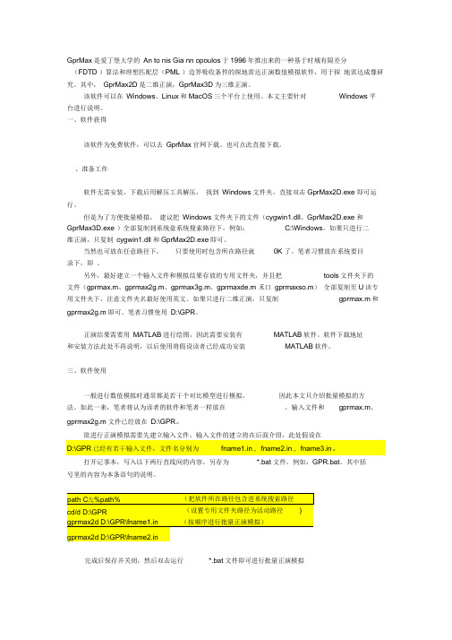
、准备工作软件无需安装,下载后用解压工具解压,找到Windows文件夹,直接双击GprMax2D.exe 即可运行。
但是为了方便批量模拟,建议把Windows文件夹下的文件(cygwin1.dll、GprMax2D.exe 和GprMax3D.exe )全部复制到系统盘系统搜索路径下,例如:C:\Windows。
如果只进行二维正演,只复制cygwin1.dll和GprMax2D.exe即可。
当然也可放在任意路径下,只要使用时包含所在路径就0K 了。
笔者习惯放在系统要目录下,即。
另外,最好建立一个输入文件和模拟结果存放的专用文件夹,并且把tools文件夹下的文件(gprmax.m、gprmax2g.m、gprmax3g.m、gprmaxde.m 禾口gprmaxso.m)全部复制至U该专用文件夹下,注意文件夹名最好使用英文。
如果只进行二维正演,只复制gprmax.m和gprmax2g.m即可。
笔者习惯使用D:\GPR。
正演结果需要用MATLAB进行绘图,因此需要安装有MATLAB软件。
软件下载地址和安装方法此处不再说明,以后使用将假设读者已经成功安装MATLAB软件。
三、软件使用一般进行数值模拟时通常都是若干个对比模型进行模拟,因此本文只介绍批量模拟的方法。
如此一来,笔者将认为读者的软件和笔者一样放在,输入文件和gprmax.m、gprmax2g.m文件已经放在D:\GPR。
7MBP75RA120型IPM富士 说明书

Switching frequency of IPM
Screw torque
Mounting (M5)
Terminal (M5)
IGBT FWD IGBT
Symbol Rth(j-c) Rth(j-c) Rth(j-c) Rth(c-f)
Symbol VDC VCC fSW -
Min. 200
13.5 1 2.5 2.5
3
2.5 Tj=125°C
2 Tj=25°C
1.5
1
0.5
0 12
13
14
15
16
17
18
Power supply voltage : Vcc (V)
Over heating protection : TcOH,TjOH (°C) OH hysterisis : TcH,TjH (°C)
Mounting (M5)
Terminal (M5)
VDC VDC(surge) VSC VCES VR IC ICP -IC PC IC ICP IF PC Tj VCC *1 Vin *2 Iin VALM *3 IALM *4 Tstg Top Viso *5
Rating
Unit
Min. Max.
IGBT-IPM
Input signal threshold voltage vs. Power supply voltage
2.5
T j=25°C T j= 1 25 ° C
2 } Vin(off)
1.5
} Vin(on)
1
0.5
0
12
13
14
15
16
17
18
Power supply voltage : Vcc (V)
多米诺大字机
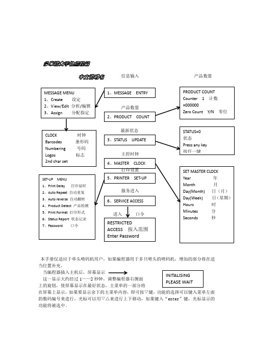
多米诺大字机编程器中文说明书本手册仅适应于单头喷码机用户,如果编程器用于多只喷头的喷码机,增加的部分将在适当位置补充。
当编程器插入主机后,屏幕显示这一显示大约经过1——2秒钟,调整编程器右侧面上的旋钮,使屏幕显示在最好状态,主菜单的一部分将在屏幕上显示,如果要显示余下的主菜单内容,即可按▽键,功能的选择可以键入菜单左面的数码编号来进行,光标可以用▽△来进行上下移动,如果键入“enter ”键,光标显示的功能将被选中。
信息输入 产品数量喷印状态在使用本机时,你应该对每一功能进行选择,以调整本机到你认为正确的状态,有些功能一旦设置就不需要改变。
喷印字体设置:在主菜单状态下,键入“5”,屏幕显示(喷印字体设置)6、Status Report (喷印机状态输出) 7、Password (口令) 输入“▽”,其他功能将被显示。
① 喷印延时喷印延时,可以不必改变喷头与传感器之间的位置,而使字符喷印在产品的不同位置上,输入“1”,屏幕显示:你可以输入4位数字(最大延时9999),此数字表明当传感器 接受信号后,不立即喷印,而是延时相应的点数以后喷印。
延时:0000 收到信号即喷印 延时:0010收到信号后延时10点喷印 延时:0050 收到信号后延时50点喷印 注:一个7×5字符为6点。
② 自动重复键人“2”,屏幕显示你可以输入01——98之间的整数,如果输入“00”,自动 重复功能失效,信息仅喷印一次,如果输入“99”,只要产品被传感器检测时,将连续重复喷印信息。
当你输入重复喷印次数后,屏幕最后一行显示Pitch=000,表示要输入两次喷印之间的点数。
如果你错输入一部分的数据,你可以键人“EXIT ”键,退到原菜单,重新选择。
③ 自动翻转自动翻转功能用于喷印在两个不同方向的产品上,例如多道流水线上产品的喷印, 键入“3”,则屏幕显示:输入喷印的翻转数(001——998),如果要取消自动翻转功能,则键入数字000即可,当用外部信号输入来控制自动翻转则必须输入999,当外部输入5V 电平时,可用于翻转喷印控制。
美格64使用说明书

美格—64使用说明书尊敬的用户您好!感谢您选用美格64系列产品。
本控制器功能超级一流,性能卓越优异,界面赏心悦目,软件操作设定及选项全中文设计;液晶屏采用蓝底白字四行八位显示模式,比黄绿屏更为美观大方。
高低级功能选择让您的控制方式更加灵活自主,直观的操作方式无须说明书片刻即可轻松完成设定。
简述其功能特点如下:1.专家自整定+模糊控制方式,更符合供水控制特点。
2.高低级功能设置,特殊场合亦可满足复杂要求。
3.界面美观,操作直观。
全中文显示,无底层代码,无说明书也能自如设定应用。
4.实时时间、目标值、频率、各泵状态、型号均可同步显示;定时换泵倒计时、巡检倒计时、公司信息、电话、消防、变频故障等等一目了然。
5.超压保护、断线报警可选;稳压巡检、无压巡检可选,控制更为安全。
6.双恒压可选,可通过开关量设定稳压值。
7.多达八时段压力控制,且每时段内均可进行任意压力设定控制及实现定时开关机功能。
8.节能智能休眠模式,主泵、小泵皆可休眠,小泵变量亦可休眠。
压力提升休眠模式,并可控制小泵进休眠状态时间。
9.大小泵优先选项,定时换泵,正负反馈功能。
10.灵活的消防及巡检组合方式,自动显示消防型号。
11.消防泵巡检间隔及时长可随意设定,消防泵故障后自动转工频运引,符合公安部最新302标准。
12.自动抑制表头抖动及系统振荡,让系统更稳定,模拟输出增益更宽可调。
13.故障记忆功能,自动记录当前10条故障信息。
14.真正的在线编程功能,擦写随意,设定时无需掉电确认。
15.软件锁及数据初始化功能。
16.超压输出设专用接点,巡检泄压阀设专用接点,方便简化外部应用电路设计。
17.独一无二的软着陆功能。
即便在循环软起的系统当中,也可获得减速停车的平稳效果。
有效抑制水锤。
18 独一无二的传感器短路错线指示功能。
接线更为安全19 个性化设计可满足用户的特殊需求。
20.强大的密匙预约功能,免除您的后顾之忧。
面板及操作说明1.面板显示分为上排数码管及下排液晶屏显示两部分。
Omega OM-CP-QUADPROCESS-100MA 四通道流量数据记录仪说明书

SpecificationsInput Channels: 4 non-isolated inputsMemory: 32,767 readings/channel Input Connection: Screw terminal Analog Conversion Time: 133 ms Frequency Rejection: 60 Hz ADC Resolution: 16 bits Current Calibration: Digital calibration available in software Calibration Date: Automatically recorded within device to alert user when calibration is required Recording Interval: 1 secondto 12 hours selectable with software Start Time: Start time and date are programmable through software Memory Wraparound: Selectable in softwareReal-Time Recording: Device can be used with PC to monitor and record data in real time Time Accuracy: +1 minute per month at 20°CU 16-Bit Resolution U P rogrammable Engineering Units, Scale Factor, and Offset ValueU Memory Wraparound U Miniature Size U U ser Calibration Through Software U Real-Time OperationOM-CP-QUADPROCESS-100MA shown actual size.Power: 9V alkaline battery(included); 120 Vac power optional Battery Life: 1 year typical Time Accuracy:±1 minute per month at 20°CData Format: Date and time stamped in µA, mA, A and other engineering units programmable through softwareWeight: 370 g (13 oz)Computer Interface: PC serial, RS-232C COM or USB (interface cable required); 2400 baudSoftware: XP SP3/Vista 7 and 8 (32-bit and 64-bit)Operating Environment: -40 to 60°C (-40 to 140°F) 0 to 95% RH non-condensing Dimensions:26 D x 112 L x 89 mm W (1.0 x 4.4 x 3.5")OM-CP-QUADPROCESSThe OM-CP-QUADPROCESS is a 4-channel, battery-powered, standalone current data logger.The OM-CP-QUADPROCESS lets the user store predefined units in the device, as well as scale factors and offset values. This allows easy, automatic linearization and scalingof any process meter that provides an analog output to process units. This portable, easy-to-use device will read and record up to 32,767 current measurements per channel.The OM-CP-QUADPROCESS represents a major leap in both size and performance. Its smallsize allows it to fit almost anywhere. Its real-time clock ensures that all data is time and date stamped. The storage medium is non-volatile solid state memory, providing maximum data security, even if the battery becomes discharged.Data retrieval is simple. Plug the logger into an available COM port and our easy-to- use software does the rest. The software converts a PCinto a real-time strip chart recorder. Data can be printed in graphical or tabular format. It can also be exported to a text or Microsoft(required to operate the data logger and sold separately).To order data loggers with optional 120 Vac power, add suffix “-AC” to model number for additional cost.Ordering Example: OM-CP-QUADPROCESS-25MA-CERT 4-channel current data logger with NIST calibration certificate and OM-CP-IFC200 Windows software with USB interface cable.OM-CP-IFC200 Windows software displays data。
GprMa中文说明指导书

GprMa中文说明指导书GprMax中GprMax2D的使用方法实验环境:操作系统:Windows7软件版本:&参考资料:[1]一、GprMax2D软件使用直接运行..\\,会出现以下窗口(也可以在命令提示符窗口输入命令运行) :输入文件名注意:要输入文件的全路径;*.in文件只要出现任何语法错误或者路径错误,软件都会自动关闭,不会有任何错误提示。
出现以下画面(,*.in的命令参考前面的文章或[1]):运行完毕会发现..\\、,复制到tools文件夹。
二、数据成像tools文件夹下有五个m文件:,, , , 。
,,其他三个以后有空再写。
;(参考[1])介电常数的;。
gprmax2g函数用于读取GprMax2D软件仿真探地雷达模型生成的二进制几何数据。
gprmax2g函数的原型:[mesh,header,media] = gprmax2g( 'filename' );media: 存储介质类型,;header: 存储模型的几何参数;: 模型的名称;: 模型在X轴每次偏移大小(单位:m);: 模型在Y轴每次偏移大小(单位:m);: 最大允许时间步长(单位:秒);: 模型在X轴的偏移次数;: 模型在Y轴的偏移次数;例子:如输入文件*.in中定义:#domain:#dx_dy:那么:=; =;= 1/(c*sqrt(1/^2+1/^2)); (其中c=299792458,为光速,公式参考[1]); =; =;mesh: 存储模型数据,M x N的数组,其中M为Y轴方向的Yee单元数目,N为X轴方向的Yee单元数目;M=,N=;:filegeo = '';[meshdata,header,media]=gprmax2g(filegeo);figure(1);[MM,NN]=size(meshdata);imagesc((1:NN)*,(1:MM)*,meshdata)axis('equal');xlabel('x(m)');ylabel('y(m)');gprmax函数用于读取GprMax2D与GprMax3D软件仿真探地雷达模型生成的二进制波形数据。
- 1、下载文档前请自行甄别文档内容的完整性,平台不提供额外的编辑、内容补充、找答案等附加服务。
- 2、"仅部分预览"的文档,不可在线预览部分如存在完整性等问题,可反馈申请退款(可完整预览的文档不适用该条件!)。
- 3、如文档侵犯您的权益,请联系客服反馈,我们会尽快为您处理(人工客服工作时间:9:00-18:30)。
GprMax中GprMax2D的使用方法V1.3实验环境:操作系统:Windows7软件版本:MATLAB7.1&GprMaxV2.0参考资料:[1]UserGuideV2.pdf一、GprMax2D软件使用1.1 直接运行..\GprMaxV2.0\Windows文件夹下的GprMax2D.exe文件,会出现以下窗口(也可以在命令提示符窗口输入命令运行) :1.2 输入文件名注意:要输入文件的全路径;*.in文件只要出现任何语法错误或者路径错误,软件都会自动关闭,不会有任何错误提示。
出现以下画面(以自带例子文件bre1.in为例,*.in的命令参考前面的文章或[1]):运行完毕会发现..\GprMaxV2.0\Windows文件夹下多了两个文件bre1.out、bre1.geo文件,复制到tools文件夹。
二、数据成像tools文件夹下有五个m文件:gprmax.m,gprmax2g.m, gprmax3g.m, gprmaxde.m , gprmaxso.m。
这里只讲gprmax2g.m,gprmax.m这两个文件的用法,其他三个以后有空再写。
gprmax3g.m是处理GprMax3D的几何数据的;gprmaxde.m用来计算Debye公式(参考[1])介电常数的;gprmaxso.m用于计算激励函数的。
2.1 gprmax2g.m的使用方法gprmax2g函数用于读取GprMax2D软件仿真探地雷达模型生成的二进制几何数据。
gprmax2g函数的原型:[mesh,header,media] = gprmax2g( 'filename' )filename是.geo文件名;media: 存储介质类型,media.type;header: 存储模型的几何参数;header.title: 模型的名称;header.dx: 模型在X轴每次偏移大小(单位:m);header.dy: 模型在Y轴每次偏移大小(单位:m);header.dt: 最大允许时间步长(单位:秒);header.nx: 模型在X轴的偏移次数;header.ny: 模型在Y轴的偏移次数;例子:如输入文件*.in中定义:#domain: 2.5 0.65#dx_dy: 0.0025 0.0025那么:header.dx=0.0025; header.dy=0.0025;header.dt = 1/(c*sqrt(1/header.dx^2+1/header.dy^2)); (其中c=299792458,为光速,公式参考[1]);header.nx=2.5/0.0025=1000; header.ny=0.65/0.0025=260;mesh: 存储模型数据,M x N的数组,其中M为Y轴方向的Yee单元数目,N为X轴方向的Yee单元数目;M=header.nx,N=header.ny;gprmax2g.m的使用例子:filegeo = 'bre1.geo';[meshdata,header,media]=gprmax2g(filegeo);figure(1);[MM,NN]=size(meshdata);imagesc((1:NN)*header.dx,(1:MM)*header.dy,meshdata)axis('equal');xlabel('x(m)');ylabel('y(m)');2.2 gprmax.m的使用方法gprmax函数用于读取GprMax2D与GprMax3D软件仿真探地雷达模型生成的二进制波形数据。
gprmax函数的原型:[Header, Fields] = gprmax( 'filename' )filename是.out文件名;1) Header:该变量包括以下成员:Header.title: 模型的名称;Header.iterations: 迭代次数;Header.dx: 在X轴每次偏移大小;Header.dy: 在Y轴每次偏移大小;Header.dt: 最大允许时间步长;Header.NSteps: 仿真次数;等于*.in文件中#analysis:命令的第一个参数;例子:如输入文件*.in中定义:#domain: 2.5 0.65#dx_dy: 0.0025 0.0025#time_window: 12e-9……#analysis: 115 bre1.out b#tx: 0.0875 0.4525 MyLineSource 0.0 12e-9#rx: 0.1125 0.4525#tx_steps: 0.02 0.0#rx_steps: 0.02 0.0#end_analysis:……那么,Header.iterations=ceil(Header.removed/Header.dt);Header.dx=0.0025;Header.dy=0.0025;Header.dt= 1/(c*sqrt(1/Header.dx^2+1/Header.dy^2));Header.NSteps=115;Header.TxStepX=0.02/Header.dx=8; Header.TxStepY=0.0/Header.dy=0; Header.RxStepX=0.02/Header.dx=8; Header.RxStepY=0.0/Header.dy=0; Header.ntx:Header.nrx:Header.nrx_box:Header.tx=0.0875/Header.dx=35;Header.ty=0.4525/Header.dy=181;Hea der.source=’MyLineSource’;Header.delay=0;(等于#tx:命令的第四个参数)Header.removed=12e-9;(等于#tx:命令的第五个参数)Header.rx=0.1125/Header.dx=45;Header.ry=0.4525/Header.dy=181;2)Fields: 该变量包括以下成员:Fields.t: 每个波形的时间轴。
数组大小Header.iterations*1;Fields.ez: Z轴方向磁矢量数据。
数组大小Header.iterations*1* Header.NSteps;Fields.hx: X轴方向电矢量数据。
数组大小Header.iterations*1* Header.NSteps;Fields.hy: Y轴方向电矢量数据。
数组大小Header.iterations*1* Header.NSteps;由于GprMax仿真是基于FDTD算法的,以上三者的关系为:详细可参考FDTD算法的相关文献。
gprmax.m的使用例子:fileout = 'bre1.out';[Header,Fields]=gprmax(fileout);N=1:Header.NSteps; %移动次数Position=Header.dx*Header.tx+(N-1)*(Header.dx*Header.TxStepX); %天线每次所在位置Data(:,:)=Fields.ez(:,1,:); %转换数组格式figure(2);imagesc(Position,Fields.t*1e9,Data);%画图colorbarxlabel('Antena Position (m)');ylabel('t(ns)');GprMaxV2.0中GprMax2D输入文件的命令实验环境:操作系统:Windows 7软件版本:MATLAB 7.1 & GprMaxV2.0参考文献:GprMaxV2.0软件manual文件夹下的UserGuideV2.pdf。
GprMaxV2.0下载地址:/Download.html说明:翻译得不好,还望大家见谅,因为我也是边看边译的。
3.1 GprMax2D命令的一般注意事项为了描述GprMax2D/3D命令及其参数,我们作以下约定:f表示浮点数(如1.5或15e-1、1.5e1)i表示整数c表示字符str表示字符串file表示输入文件名所有空间距离的基本单位为米所有时间的基本单位为秒所有频率参数的基本单位是Hz3.2 GprMax2D 2.0版本共有32条命令:#title:#domain:#dx_dy:#time_step_stability_factor:#time_window:#messages:#number_of_media:#nips_number:#media_file:#geometry_file:#medium:#abc_type:#abc_order:#abc_stability_factors:#abc_optimization_angles: #abc_mixing_parameters: #pml_layers:#box:#cylinder:#x_segment:#y_segment:#triangle:#analysis:#end_analysis:#tx:#rx:#rx_box:#snapshot:#tx_steps:#rx_steps:#line_source:#excitation_file:以下可以运行于GprMax中的命令在GprMax2D版本2.0中将不再支持:#scan:#csg:#extra_tx:另外,一些命令的旧的参数规则亦发生了变化:#tx:#snapshot:3.3 GprMax2D命令参数为了更好地介绍GprMax2D命令,我们将它们分成四类:一般命令:包括用于指定的大小和模型的离散ABC相关命令: 允许定制和优化吸收边界条件介质和对象的构造命令: 用不同的参数来在模型中引入不同的介质和构造简单的几何形状激励和输出命令:用来放置源代码和模型的输出点运行GprMax2D最低限度的命令如下:•#domain:•#dx_dy:•#time_window:•至少一个#analysis:及与其对应的结束命令#end_analysis:至少一个#tx:与#rx:,或者#rx_box:命令• 为了使#tx: 命令正确运行,同时需要一行新的#line_source:命令3.3.1一般命令#title:模型的题目#title: strStr即是模型的题目,必须是单行的。
#domain:模型的范围(单位:米)#domain: f1 f2f1与f2分别代表x和y轴上的量度大小#domain: 1.0 1.5表示1.0*1.5的大小范围#dx_dy:表示x和y轴上的偏移量(如△x、△y)#dx_dy: f1 f2表示x轴偏移f1和y轴方向上偏移f2#domain: 1.0 1.5#dx_dy: 0.1 0.1则模型的单元数为10*15#domain: 1.0 1.5#dx_dy: 0.01 0.01则模型的单元数为100*150最大允许时间步△t与△x、△y的约束关系如下:(3.1)C为光速,GprMax2D中计算△t使用3.1式等号。