TS系列温度传感器简介
TS—A型温度传感技术实验仪使用说明
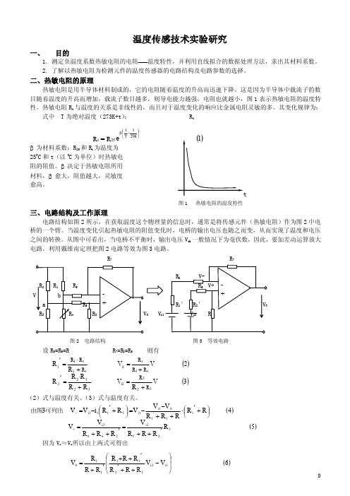
温度传感技术实验研究一、目的1. 测定负温度系数热敏电阻的电阻2. 了解以热敏电阻为检测元件的温度传感器的电路结构及电路参数的选择。
二、热敏电阻的原理热敏电阻是用半导体材料制成的,它的电阻随着温度的升高而迅速下降。
这是因为半导体中载流子的数目随着温度的升高而增加,载流子数目越多,则导电能力越强,电阻也就越小,图1表示热敏电阻的温度特性。
热敏电阻Rt与温度的关系是非线性的,而且对于温度变化的响应比金属电阻灵敏的多。
其变化规律为:式中 T为绝对温度(273K+t); Rtβ为材料系数;R25和R t为温度为250C和t(以0C为单位)时热敏电阻的阻值。
β决定于热敏电阻所用材料,β愈大,阻值越大,灵敏度愈高。
图1 热敏电阻的温度特性三、电路结构及工作原理电路结构如图2所示,在获取温度这个物理量的信息时,通常是将传感元件(热敏电阻)作为图2中电桥的一个臂。
当温度变化引起热敏电阻的阻值变化时,电桥的输出电压也随之而变,从而实现了温度和电压之间的转换。
从图中可看出,当电桥不平衡时,输出电压Vab一般情况下为毫伏数,因此,要加差动运算放大电路。
利用戴维南定理把图2电路等效为图3电路。
R7R7V图2 电路结构图3 等效电路设R5=R6=R R7=R8=Rf则有(2)式与温度有关、(3)式与温度有关。
因为V-≈V+所以由上两式可得出e2981T125t RR⎪⎭⎫⎝⎛-β=()()3VRVRRRRR2VVRRRRRRRRRR323i232322t1ti1t1t11+=+⋅='+=+⋅='()()5RRRRVRRRVV4RRRRRVVVRRiVV3f2f2i2682i1f'11i1i5111i'++='++=⎪⎭⎫⎝⎛+'⋅++--=⎪⎭⎫⎝⎛+'-=+-可列出由图()6VVRRRRV1i2i1ff0⎪⎪⎫⎛-''++'=上式中R 1′和V i1与温度有关,所以(6)式就是温度传感器电压 温度特性表达式。
红外温度传感器PPT(完整版)

物的出现的检测等等。
吸收体
红外温度传感器的内部构造
黑体
硅介质滤光片(对红 外光完全无干扰)
DIE
环境温度传感器
封装尺寸
一端(热端)与另一端(冷端)之间通过腐蚀方法形成的非常薄的薄膜进行热隔离。
滤光片中心波长:5um
TS118-3详细规格
滤光片中心波长:5um
作为补偿信号输入MCU
硅介质滤光片(对红外光完全无干扰)
滤光片中心波长:5um 内置环境温度传感器:NI
滤光片中心波长:8-14um 内置环境温度传感器:NI
滤光片中心波长:5um 内置环境温度传感器: 0.5%NTC
滤光片中心波长:8-14um 内置环境温度传感器: 0.3%NTC
传感器的正确使用
正确
错误
我们将提供8种标准的模组供选择,并且模组的镜头角度可以满足大部分的应用环境。 热电堆式是电动势发生变化,而(pyroelectric)焦变体式是电荷发生变化 滤光片中心波长:8-14um TS118-3详细规格 也可以依据需要安装的距离来计算可测量的最佳目标物大小。 TS系列可提供TO-5和TO-18两种封装,也有各种不同型式的滤波器供选择。 与pyroelectric(焦电体的共同点和区别 滤光片中心波长:8-14um 一端(热端)与另一端(冷端)之间通过腐蚀方法形成的非常薄的薄膜进行热隔离。 先在硅基片上沉淀出多个热偶接点(thermojunction)。 所以镜头的选择,目标物距离的计算尤为重要。 在这里环境温度传感器Ni型就有优势,因为其输出是线性,故计算方式也较简单。 热电堆式-Thermopile红外温度传感器原理 另依据角度的参数,然后依据目标物的尺寸可以算出需要安装的最佳距离; 滤光片中心波长:5um 滤光片中心波长:8-14um 作为补偿信号输入MCU
红外温度传感器ppt课件

滤光片中心波长:5um 内置环境温度传感器:NI
滤光片中心波长:8-14um 内置环境温度传感器:NI
滤光片中心波长:5um 内置环境温度传感器: 0.5%NTC
滤光片中心波长:8-14um 内置环境温度传感器: 0.3%NTC
9
传感器的正确使用
MCU
给出控制信号
可实现温度 的循环控制
6
应用原理框图二 MCU内部处理原理
MCU
NTC线性处理
温度补偿处理 线性化处理
接口电路
数字输入
推荐芯片
OUTPUT
FORTUNE FS511系列
7
温度补偿的计算方法
输出电压
常数
目标物辐射率
•Utp为采集的传感器电压输出数据值,依 据目标物体的辐射率以及环境的温度采集 值可以算出目标物体的温度。
正确
错误
由于该传感器是接收由透镜入射的红外光,所以范围非常重要,如果被 测物体以外的红外光也被采集,就意味着非被测物体的信息也被采集,从而 影响到测量的准确性。所以镜头的选择,目标物距离的计算尤为重要。
10
可以直接使用的模块
11
模块的选择
1.目标物的温度范围 2.环境温度的范围 3.目标物的尺寸(需测量范围) 4.目标物的距离 5.滤光片的选择 6.目标物体的材质
红外温度传感器
热电堆式-Thermopile
1
热电堆式-Thermopile红外温度传感器原理
任何物体的表面都会辐射出红外线,TS系列传感器能够吸收红外线能量并输出一 个与温度成比例关系的电压信号。TS系列红外温度传感器由热吸收区(热端)、硅基片 (冷端)和Sinx薄膜及外封装组成。其工作原理类似于普通的热电偶原理,是基于塞贝 克效应(温差电势效应)。先在硅基片上沉淀出多个热偶接点(thermojunction)。这些热 偶接点串联在一起形成一个热感应通道(thermopile)。一端(热端)与另一端(冷端)之间 通过腐蚀方法形成的非常薄的薄膜进行热隔离。红外吸收区域与热端合并在一起以使 热端能升温,这样,与红外线能量成正比的热电势便可产生(见下图)。TS系列可提供 TO-5和TO-18两种封装,也有各种不同型式的滤波器供选择。同时,对于某些OEM用 户,也可提供无封装的芯片。
TS-Touchswitch 皮带跑偏传感器 TS1-TS2系列安装使用说明书
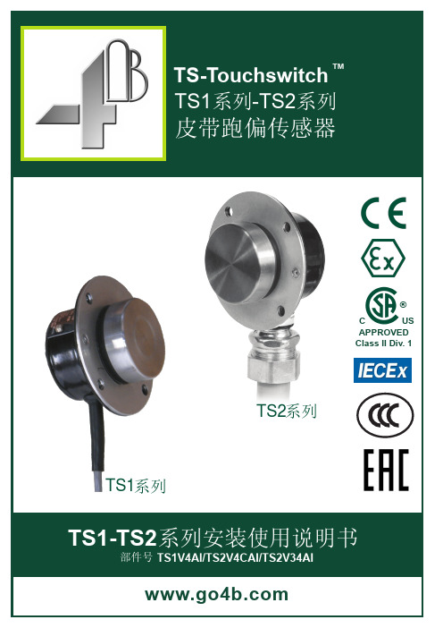
皮带跑偏传感器TS1-TS2系列安装使用说明书部件号 TS1V4AI/TS2V4CAI/TS2V34AITS1系列TS2系列APPROVED Class II Div. 1C US ®TS1系列与TS2系列的唯一区别是TS1为线入式,不带导线密封管螺纹接口;TS2带1/2英寸NPT 导线密封管螺纹接口。
除此之外,两个系列产品完全一样。
TS2V34AI 指示灯为绿色,其余所有TS 系列产品指示灯为红色。
TS1系列不带导线密封管接口螺纹传感器出线没有额外保护TS2系列带导线密封管接口螺纹内螺纹尺寸:1/2" NPT尊贵的4B产品用户:感谢购买4B产品和对4B公司的信任!安装使用产品前请务必认真完整阅读并理解本说明书的全部内容。
所有4B产品都有相应的涉及安全的基本要求,为保证您购买的产品长期安全高效地工作,务必特别留意相关的安全须知。
如不严格遵守相关的安全要求可能带来严重伤害甚至死亡事故。
客户安全须知1. 必须完整阅读所有与本产品有关的全部文字说明必须认真阅读并完全理解有关责任、安装操作和安全说明才能安全有效地使用本产品。
2. 必须彻底弄清您的真正需求是什么每个客户都独一无二,每个应用也是如此。
所以只有用户自身才真正了解自己的需求,才真正了解自己设施运行的能力。
如有需要了解更多4B产品性能或有技术疑问请登录我公司网站h ttp://或拨打公司服务热线电话189****6321,我们的专业工程师随时为您解答疑问。
3. 选择有资质、能力强的安装公司4B正确合理的安装对设备的安全和运行至关重要。
如果您请 以外的公司进行安装,务必找那些有资质、有经验的电气安装公司进行设备安装。
4.建立并严格遵循定期检查维护计划建立并严格遵循定期检查维护计划,确保您的系统一直处于良好的工作状态。
如何确立定期检查的周期客户最有发言权,客户了解到的观察指标越多,制定的检修周期越适当。
这些指标包括但不仅限于:天气状况、生产设施的结构、设备运行的时间长度、动物或昆虫寄生状况、对自己员工执行力的了解等等。
T TT 系列插入式温度传感器 变送器 说明书

T/TT系列插入式温度传感器/变送器使用说明书使用范围:T/TT系列插入式温度传感器/变送器主要是针对各类工业及商业空调等系统的插入式和恶劣环境下的温度检测和控制而设计。
可用于各类工厂车间、净化间、实验室、机房、办公及商业建筑、机场、车站、博物馆、体育馆等空调系统风管,水管和蒸汽管等需要插入式安装的温度检测。
主要特点:●采用高精度传感器,抗干扰能力强。
●良好的长期稳定性和可靠性●坚固外壳设计,防护可达IP65●多种输出方式可选●工作温度范围较广●响应速度快●安装方式灵活技术指标:T2/T4系列温度传感器传感器:热电阻(RTD),见选型表输出:阻值(Ω),见选型表精度:见选型表接线方式:两线制或三线制注:接线方式一般采用两线制,三线制可适度提高精度。
TT2/TT4系列温度变送器传感器:PT100/PT1000(A级)量程:-40~100°C ,见选型表输出:4~20mA or 0~10VDC精度:<±0.5°C@25°C电源:电压输出24VAC/DC±10%电流输出24VDC±10%负载电阻:500Ω工作环境:-40~70°C, 0~95%RH存贮温度:-40~80°C材料:ABS外壳,不锈钢探头和套管防护等级:IP65安装方式:T2/TT2风管安装,T4/TT4管道安装。
T4=T2+套管,TT4=TT2+套管选型表:注:T2配以安装套管后即为T4。
二.接线图:由于选型不同,其端子及接线会不同,具体应按产品上盖内侧接线图接线。
321+VGND POWER SUPPLY 24VDC 24VAC0 (10V)﹒电压(0-10V)输出型:﹒电流(4-20mA)输出型:+V VT GND T24VDCPOWER SUPPLY A4…20mA﹒热电阻输出型:TT2/4接线图T2/4接线图二线制连接使用端子1和2三线制连接使用端子1、2和3外形尺寸图(mm):TT2/4:T2/4:固定卡件:剖面 A-A安装套管:安装图(mm):风管安装方式:水管安装方式:则接头长度为:A=L-25-1/2●建议TT2采用固定卡件安装,T2必须用。
TS10
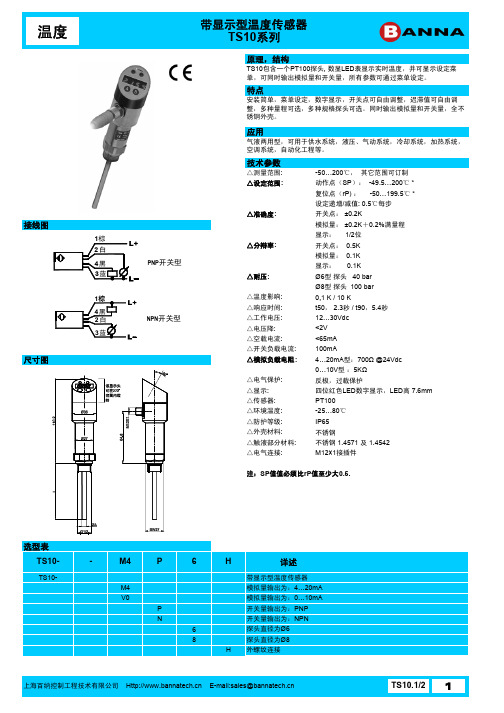
ST04-
PU
02
F
ET04ST04-
PU 02 05 10 F
G
详述
M12四芯 附线接插件
自接线式M12 附线接插件
PUR材质
2米长
5米长
10米长
母插头
G
直型
W
弯型
上海百纳控制工程技术有限公司 E-mail:sales@
TS10.2/2 2
应用
气液两用型,可用于供水系统,液压、气动系统,冷却系统,加热系统, 空调系统,自动化工程等。
技术参数
△测量范围: △设定范围 :
△准确度:
△分辩率:
△耐压:
△温度影响: △响应时间: △工作电压: △电压降: △空载电流: △开关负载电流: △模拟负载电阻 :
△电气保护: △显示: △传感器: △环境温度: △防护等级: △外壳材料: △触液部分材料: △电气连接:
TS10.1/2 1
温度
带显示型温度传感器 TS10系列
特色功能——可调迟滞
TS10系列产品中的迟滞值可通过菜单设定,右图为迟滞功能示 意,灰色带为迟滞值,即SP-rP.当压力上升时 ,只有压力值大 于SP,开关点才断开; 而当压力值下降时,只有压力值小rP, 开关点才闭合。 可调迟滞功能可满足多种工业现场的要求,
注:SP值值必须比 rP值至少大 0.5.
选型表
TS10-
-
M4
P
6
H
详述
TS10-
带显示型温度传感器
M4
模拟量输出为:4…20mA
V0
模拟量输出为:0…10mA
P
开关量输出为:PNP
N
开关量输出为:NPN
最新版XW-TS1120使用说明书
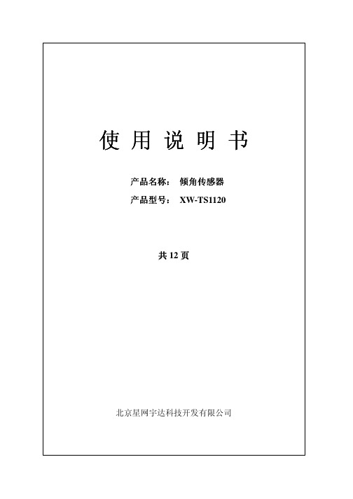
hexadecim *FF
al
单位
说明
CMD 消息协议头
输出格式设置标识
输出的端口 (COM1,COM2……) ASC------ASCII 码无温度输出方式 hex, integer-----16 进制定点输出方式 hex,float---------16 进制浮点输出方式
效验(使用 FF 作为校验)
使用说明书
产品名称: 倾角传感器 产品型号: XW-TS1120
共 12 页
北京星网宇达科技开发有限公司
北京星网宇达科技开发有限公司
XW-TS1120
1 产品简介 XW-TS1120 倾角传感器是北京星网宇达科技开发有限公司自主研发的高精
度双轴倾角传感器。主要用于静态测量载体相对于水平面的倾斜角度。产品具有 1~5 阶数字滤波器,用户可根据使用环境及需求进行设置;产品输出速率可调, 最高可达 100Hz。XW-TS1120 倾角传感器可用于科研、机械制造、设备安装、道 路桥梁、建筑工程、自动控制等方面。
举例
单位
说明
string
$CMD
CMD 消息协议头
string string
SET,OUTPUTRA TE COM1
numeric
005
hexadecimal *FF
输出速率设置标识
输出的端口 (COM1,COM2……) 输出频率选择 000Hz(问答方式) 001Hz 002Hz 005Hz 010Hz(默认) 020Hz 050Hz 100Hz 效验(使用 FF 作为校验)
50 次/秒
0x64
设置输出速度
100 次/秒
0xa0
单次输出
每发送一次 0xa0 命令输出一次数据,掉电保存状态
Endress+Hauser iTHERM TS111 温度传感器说明书
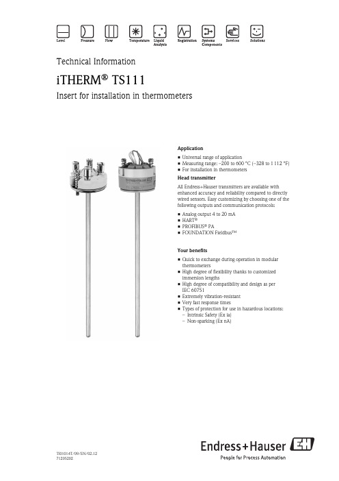
Application•Universal range of application•Measuring range: –200 to 600 °C (–328 to 1 112 °F)•For installation in thermometers Head transmitterAll Endress+Hauser transmitters are available with enhanced accuracy and reliability compared to directly wired sensors. Easy customizing by choosing one of the following outputs and communication protocols:•Analog output 4 to 20 mA •HART ®•PROFIBUS ® PA•FOUNDATION Fieldbus™Your benefits•Quick to exchange during operation in modular thermometers•High degree of flexibility thanks to customized immersion lengths•High degree of compatibility and design as per IEC 60751•Extremely vibration-resistant •Very fast response times•Types of protection for use in hazardous locations:–Intrinsic Safety (Ex ia)–Non-sparking (Ex nA)Technical InformationiTHERM ® TS111Insert for installation in thermometersTI01014T/09/EN/02.1271205202iTHERM® TS111Function and system designMeasuring principle The iTHERM® TS111 is an universal temperature measuring element which can be used as a replaceableinsert as per DIN 43735 for modular thermometers and thermowells as per DIN 43772. For this insert, aPt100 is used as the temperature sensor in accordance with IEC 60751. This is a temperaturesensitiveplatinum resistor with a resistance of 100 W bei 0 °C (32 °F) and a temperature coefficient a = 0.003851°C-1.There are generally two different kinds of platinum resistance thermometers:•Wire wound (WW): Here, a double coil of fine, high-purity platinum wire is located in a ceramicsupport. This is then sealed top and bottom with a ceramic protective layer. Such resistance thermometersnot only facilitate very reproducible measurements but also offer good long-term stability of theresistance/temperature characteristic within temperature ranges up to 600 °C (1112 °F). This type ofsensor is relatively large in size and it is comparatively sensitive to vibrations.•Thin film platinum resistance thermometers (TF): A very thin, ultrapure platinum layer, approx. 1m m thick, is vaporized in a vacuum on a ceramic substrate and then structured photolithographically. Theplatinum conductor paths formed in this way create the measuring resistance. Additional covering andpassivation layers are applied and reliably protect the thin platinum layer from contamination andoxidation, even at high temperatures.The primary advantages of thin film temperature sensors over wire wound versions are their smaller sizesand better vibration resistance. A relatively low principle-based deviation of the resistance/temperaturecharacteristic from the standard characteristic of IEC 60751 can frequently be observed among TF sensors athigh temperatures. As a result, the tight limit values of tolerance category A as per IEC 60751 can only beobserved with TF sensors at temperatures up to approx. 300 °C (572 °F).2Endress+HauseriTHERM® TS111Mechanical constructionå 1Design of the iTHERM® TS1111Insert with head transmitter mounted (example with Æ3 mm (1/8 in))2Insert with terminal block mounted (example with Æ6 mm (1/4 in))3QuickSens insert with terminal block mounted (example with Æ3/6 mm (1/8 / 1/4 in))4Terminal head5Protection armatureE Extension neck lengthL Immersion lengthIL Insertion lengthX Variable for calculating the length of the insert (thermometer-dependent variable)The insert comprises three main components: the sensor at the tip, an electrical connection at the upper endand a mineral insulated sheathed cable or stainless steel tube with insulated wires in between. In themeasuring tip, the sensor element is (depending on the sensor type) either firmly embedded in a sensor capby means of ceramic potting, soldered onto the bottom of the sensor cap or embedded in compressedmineral insulation.The insert comes with free wires for the electrical connection, if this is to be connected directly to a headtransmitter. Alternatively, a ceramic terminal block can be used which is mounted securely on a washer. Endress+Hauser3iTHERM® TS111 Dimensions All dimensions in mm (in).å 2Dimensions iTHERM® TS1111Insert with terminal block mounted (example with Æ6 mm (1/4 in))2Insert with head transmitter mounted (example with Æ3 mm (1/8 in))3Insert with flying leads (standard version)4QuickSens insert with terminal block mounted (example with Æ3/6 mm (1/8 / 1/4 in))E Extension neck lengthÆID Insert diameterIL Insert lengthL Immersion lengthÆX Thermowell diameterTip shape4Endress+HauseriTHERM ® TS111Endress+Hauser 5Sheath material, insertThe temperatures for continuous operation specified in the following table are intended only as reference values when using the various materials in air. In exceptional cases, the maximum operating temperatures are sometimes significantly lower.Performance characteristicsSensor technology,measurement rangeRTD resistance thermometeriTHERM ® TS1116Endress+HauserMaximum measured errorRTD resistance thermometer corresponding to IEC 607511)|t| = absolute value °CFor measurement errors in °F, calculate using equations in °C, then multiply the outcome by 1.8.Temperature rangesResponse time Tested in accordance with IEC 60751 in flowing water (0.4 m/s at 30 °C):iTHERM ® TS111Endress+Hauser 7Response time for insert without transmitter.Insulation resistanceInsulation resistance according to IEC 60751 > 100 M W at 25 °C measured using a minimum test voltage of 100 V DC.Dielectric strengthDielectric strength between terminals and insert sheath:•For all Æ6 mm (1/4 in) inserts: ³ 1 000 V DC for 5 s •For Æ3 mm (1/8 in) QuickSens: ³ 500 V DC for 5 s •For all other Æ3 mm (1/8 in) inserts: ³ 250 V DC for 5 sSelf-heatingRTD elements are passive resistance temperature sensors which must be supplied with a measuring current in order to determine the measured values. This measuring current causes the RTD element to self-heat,which constitutes an additional measuring error. The extent of this measuring error is influenced not only by the measuring current but also by the temperature conductivity and the thermal coupling of the resistance sensor with the environment. The self-heating is negligible if an iTEMP ® temperature transmitter (extremely low measuring current) from Endress+Hauser is used.Transmitter specifications1)% is related to the adjusted measurement range (the larger value applies)iTHERM® TS1118Endress+Hauser More information on this can be found in the Technical Information (see the section"Documentation").Power supplyWiring diagrams Type of sensor connectioniTHERM® TS111Operating conditionsInstallation conditions OrientationNo restrictions.Installation optionsThe iTHERM® TS111 insert can be mounted in thermometers with a flat face terminal head as perDIN EN 50446. When installing in a thermometer with a thermowell, the insert is secured in thethermometer's terminal head by means of spring loaded screws. This means that the insert tip is alwayspressed against the internal floor of the thermowell, thereby ensuring good thermal contact.The prerequisite is that the insert length (IL) must be adapted to the thermowell. This can be calculated bymeans of the following formula: IL = E + L + X (E = extension neck length, L = immersion length of thethermowell, X = variable for calculating the length of the insert). The electrical connection is performed asdescribed in the section "Power supply".å 3General installation options: in an assembly with thermowell (left), direct measurement (right)Minimum immersion depthHeat loss error £ 0.1 K; measured in accordance with IEC 60751 at 100 °C in liquid mediumEndress+Hauser9iTHERM ® TS11110Endress+HauserDelivery conditionInserts with an insertion length of IL > 1 000 mm (39.4 in) are delivered coiled. With the insert you will receive instructions for exchanging the coiled insert.Possible bending radiusAmbient temperatureShock and vibration resistanceThe Endress+Hauser inserts exceed the IEC 60751 requirements stating a shock and vibration resistance of 3 g in a range of 10 to 500 Hz.The vibration resistance of the measurement point depends on sensor type and construction. Refer to the following table:1)(measured in accordance with IEC 60751 with changing frequencies in the range of 10…500 Hz)iTHERM ® TS111Endress+Hauser 11Shock resistance³ 4 J (measured in accordance with IEC 60079-0)Components, human interfaceFamily of temperaturetransmitters Thermometers fitted with iTEMP ® transmitters are an installation-ready complete solution to improve temperature measurement by significantly increasing accuracy and reliability, when compared to directwired sensors, as well as reducing both wiring and maintenance costs.PC programmable head transmittersThey offer a high degree of flexibility, thereby supporting universal application with low inventory storage.The iTEMP ® transmitters can be configured quickly and easily at a PC. Endress+Hauser offers freeconfiguration software which can be downloaded from the Endress+Hauser Website. More information can be found in the Technical Information.HART ® programmable head transmittersThe transmitter is a 2-wire device with one or two measuring inputs and one analog output. The device not only transfers converted signals from resistance thermometers and thermocouples, it also transfers resistance and voltage signals using HART ® communication. It can be installed as an intrinsically safe apparatus in Zone 1 hazardous areas and is used for instrumentation in the terminal head (flat face) as per DIN EN 50446.Swift and easy operation, visualization and maintenance by PC using operating software, Simatic PDM or AMS. For more information, see the Technical Information.PROFIBUS ® PA head transmittersUniversally programmable head transmitter with PROFIBUS ® PA communication. Conversion of various input signals into digital output signals. High accuracy over the complete ambient temperature range. Swift and easy operation, visualization and maintenance using a PC directly from the control panel, e. g. using operating software, Simatic PDM or AMS. For more information, see the Technical Information.FOUNDATION Fieldbus™ head transmittersUniversally programmable head transmitter with FOUNDATION Fieldbus™ communication. Conversion of various input signals into digital output signals. High accuracy over the complete ambient temperature range.Swift and easy operation, visualization and maintenance using a PC directly from the control panel, ing operating software such as ControlCare from Endress+Hauser or NI Configurator from National Instruments. For more information, see the Technical Information.Advantages of the iTEMP ® transmitters:•Dual or single sensor input (optionally for HART ® transmitter)•Unsurpassed reliability, accuracy and long-term stability in critical processes•Mathematical functions•Monitoring of the thermometer drift, sensor backup functionality, sensor diagnostic functions •Sensor-transmitter matching based on Callendar/Van Dusen coefficientsiTHERM ® TS11112Endress+HauserCertificates and approvalsCE Mark The device meets the legal requirements of the EC directives if applicable. Endress+Hauser confirms that the device has been successfully tested by applying the CE mark.Hazardous area approvals For further details on the available Ex versions (ATEX, CSA, FM etc.), please contact your nearest Endress +Hauser sales organization. All relevant data for hazardous areas can be found in separate Ex documentation.Other standards and guidelines •IEC 61010-1: Protection Measures for Electrical Equipment for Measurement, Control, Regulation and Laboratory Procedures•IEC 60751: Industrial platinum resistance thermometers•DIN 43735: Exchangeable inserts for resistance thermometers and thermocouples•IEC 61326-1: Electromagnetic compatibility (electrical equipment for measurement, control and laboratory use - EMC requirements)Material certification The material certificate 3.1 (according to standard EN 10204) can be directly selected from the sales structure of the product and refers to the parts of the sensor in contact with the process fluid. Other types of certificates related to materials can be requested separately. The "short form" certificate includes a simplified declaration with no enclosures of documents related to the materials used in the construction of the single sensor and guarantees the traceability of the materials through the identification number of thethermometer. The data related to the origin of the materials can subsequently be requested by the client if necessary.Test report and calibration The "Factory calibration" is carried out according to an internal procedure in a laboratory of Endress+Hauser accredited by the European Accreditation Organization (EA) according to ISO/IEC 17025. A calibration which is performed according to EA guidelines (SIT/Accredia or DKD/DAkks calibration) may be requested separately. The calibration is performed on the replaceable insert of the thermometer. In the case ofthermometers without a replaceable insert, the entire thermometer - from the process connection to the tip of the thermometer - is calibrated.CalibrationCalibration of thermometersCalibration involves comparing the measured values of a device under test (DUT) with those of a moreprecise calibration standard using a defined and reproducible measurement method. The aim is to determine the deviation of the DUT's measured values from the true value of the measured variable. Two different methods are used for thermometers:•Calibration at fixed-point temperatures, e.g. at the freezing point of water at 0 °C,•Calibration compared against a precise reference thermometer.The thermometer to be calibrated must display the fixed point temperature or the temperature of the reference thermometer as accurately as possible. Temperature-controlled calibration baths with very homogeneous thermal values, or special calibration furnaces into which the DUT and the reference thermometer, where necessary, can project to a sufficient degree, are typically used for thermometer calibrations.Evaluation of thermometersIf a calibration with an acceptable uncertainty of measurement and transferable measurement results is not possible, Endress+Hauser offers customers a thermometer evaluation measurement service, if technically feasible. This is the case when:•The process connections/flanges are too big or the immersion length (IL) is too short to allow the DUT to be immersed sufficiently in the calibration bath or furnace, or•Due to heat conduction along the thermometer tube, the resulting sensor temperature generally deviates significantly from the actual bath/furnace temperature.The measured value of the DUT is determined using the maximum possible immersion depth and the specific measuring conditions and measurement results are documented on an evaluation certificate.Sensor transmitter matchingThe resistance/temperature curve of platinum resistance thermometers is standardized but in practice it is rarely possible to keep to the values precisely over the entire operating temperature range. For this reason,platinum resistance sensors are divided into tolerance classes, such as Class A, AA or B as per IEC 60751.These tolerance classes describe the maximum permissible deviation of the specific sensor characteristic curve from the standard curve, i.e. the maximum temperature-dependent characteristic error that is permitted. The conversion of measured sensor resistance values to temperatures in temperature transmittersiTHERM ® TS111Endress+Hauser 13or other meter electronics is often susceptible to considerable errors as the conversion is generally based on the standard characteristic curve.When using E+H temperature transmitters, this conversion error can be reduced significantly by sensor-transmitter matching:•Calibration at several temperatures and determination of the actual temperature sensor characteristic curve,•Adjustment of the sensor-specific polynomial function using Calendar-van Dusen (CvD) coefficients,•Configuration of the temperature transmitter with the sensor-specific CvD coefficients for resistance/temperature conversion, and•Optionally another calibration of the reconfigured temperature transmitter with connected resistance thermometer.Endress+Hauser offers its customers this kind of sensor-transmitter matching as a separate service.Furthermore, the sensor-specific polynomial coefficients of platinum resistance thermometers are always provided on every E+H calibration certificate so that users themselves can also appropriately configure suitable temperature transmitters.For the device, Endress+Hauser offers standard calibrations at a reference temperature of–80 to +600 °C (–112 to +1 112 °F) based on the ITS90 (International Temperature Scale). Calibrations in other temperature ranges are available from your Endress+Hauser sales center on request. Calibrations are traceable to national and international standards. The calibration certificate is referenced to the serial number of the thermometer.Only the insert is calibrated.Minimum insertion length (IL): ⌀3 mm 1)1)Required minimum insertion length (IL) for inserts to perform a correct calibration.Minimum insertion length (IL): ⌀6 mm 1)iTHERM ® TS11114Endress+HauserOrdering informationDetailed ordering information is available from the following sources:•In the Product Configurator on the Endress+Hauser website: ® Select country ®Instruments ® Select device ® Product page function: Configure this product•From your Endress+Hauser Sales Center: /worldwideProduct Configurator - the tool for individual product configuration•Up-to-the-minute configuration data•Depending on the device: Direct input of measuring point-specific information such as measuring range or operating language•Automatic verification of exclusion criteria•Automatic creation of the order code and its breakdown in PDF or Excel output format•Ability to order directly in the Endress+Hauser Online ShopDocumentationTechnical information:iTEMP ® temperature head transmitter:–TMT180, PC-programmable, 1-channel, Pt100 (TI00088R)–TMT181, PC-programmable, 1-channel, RTD, TC, W , mV (TI00070R)–TMT182 HART ®, 1-channel, RTD, TC, W , mV (TI078R)–TMT82 HART ®, 2-channel, RTD, TC, W , mV (TI01010T)–TMT84 PROFIBUS ® PA, 2-channel, RTD, TC, W , mV (TI00138R)–TMT85 FOUNDATION Fieldbus™, 2-channel, RTD, TC, W , mV (TI00134R)Hazardous area supplementary documentation:iTHERM ® TS111, TM211 Omnigrad TST310, TSC310 Omniset TPR100, TPC100 IECEx Ex ia IIC T6…T1(XA00100R)Instruments International Endress+Hauser Instruments International AG Kaegenstrasse 24153 ReinachSwitzerlandTel.+41 61 715 81 00Fax+41 61 715 25 00***************.comTI01014T/09/EN/02.12 71205202EH-COSIMA ProMoDo。
Atmd推出AT30TS750系列高精度数字温度传感器
线 系统, 以及多种低功率通信系统。
’q ; ‰ 辜渺 料 砩嚣 l }
器、 吸尘器等 。
B 叠■ 1 I _● R— =_ }
托
鬣
∞ 阳 o ●
镛
∞
甜B
m疃f e 一 ,
黛 簟
— — 簟
,
Hale Waihona Puke 镶 蘩 冉i 蛩 ’ 镌 籀
点 在 于全 系列 规(4 ~ 5 、 _ 电压 22 55 口建 R 一 0 8 ℃)J 作 . . ~ V、 — T p C O yeL DC M、高电流驱 动 L D功 能 、 功 能复用 及最 大 E I 化 、快速 1一 i / 2 bt D及多 口 P A WM、口建高精 准度 R C振荡 电 路、 休眠快速唤醒 、 高低 双频 系统操 作切换 及全系列提供 R C T 等功能 , 实为功能 、 性能 、 价格最具竞争力 的 MC U系列。整系 列功能涵盖 面广 , 可满足客户不 同档次产 品需求 , 特别适合应
r _ 行 业 视 点
1 d syP r ete nut es cv r p i
活 , 用于 网络 、 适 通信 、 存储 、 服务器 、 嵌入式计 算和广播 视频
系 统 , 适 用 于 F G 串 行 / 串 器 ( r e) 多 速 率 时 钟 也 P A、 解 S Ds e 和
应用。
用 于 小 家 电 产 品 , 如 : 发器 、 例 直 电子 锅 、 电风 扇 、 浆 机 、 电 豆 充
在 2 M p 采样速率下 ,T 2 4 5 ss L C 10的 l 4位和 1 2位版本 每通 道 的功耗仅为 2 rw,而 15 p T 2 4 4 o 2 Mss C 15每通 道的功耗则 仅 L
西门子SITRANS T 温度传感器操作说明说明书
2 安全说明 ........................................................................................................................................ 11
2.1 2.1.1 2.1.2 2.1.3
1.7
运输与存储.................................................................................................................... 9
1.8
保修注意事项 ................................................................................................................ 9
Siemens AG Digital Industries Postfach 48 48 90026 NÜRNBERG
德国
文件订购号: A5E03920348 Ⓟ 09/2020 本公司保留更改的权利
Copyright © Siemens AG 2020. 保留所有权利
目录
1 简介................................................................................................................................................. 7
3 安装/固定 ....................................................................................................................................... 17
泰勒士自动化科技有限公司 TS-TWI4 壁挂式温度变送器使用说明书
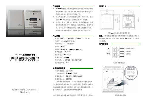
TS-TWI4系列温度传感器产品使用说明书厦门泰勒士自动化科技有限公司版本号V1.2产品概述※TS-TWI4型壁挂式温度变送器采用原装进口的数字型温度传感模块,通过高性能单片机的信号处理,性能远优于普通热电阻和电偶型温度传感器产品。
※该系列变送器采用灵活的壁挂式安装,使用方便,输出标准4-20mA电流信号,适用于大多数工控设备。
※该系列产品为一体化温度变送器,内置温度探头,直接输出工控模拟量信号,精度高,传输距离远,稳定性更高。
已广泛应用于楼宇自动化、气候与暖通信号采集、博物馆和宾馆的气候站、大棚温室以及医药行业等。
产品参数量程:0~+50℃/-20~+80℃/-40~+60℃(可设置)准确度:±0.5℃(全量程均值)产品功耗:15mA(典型值)分辨率:0.1℃响应时间6τ(63%):min=5s,max=30s长期稳定性:<0.1℃/年输出信号:4-20mA电流负载电阻:<500ohm供电电源:15~36VDC(建议值24VDC)建议校对年限:两年工作和存储环境工作环境温度:-20~+80℃工作环境湿度:0~99.9%无冷凝存储温度:10–50°C(0–125°C peak)存储湿度:20–60%RH工作环境注意防尘措施,产品安装位置应该避免进出风口、临近机柜等发热体,以及远离强电磁干扰源等。
测量点应选择温湿度状态值相对稳定,能代表区域状况的位置。
上电一段时间后,方能得到现场准确温度数值。
(注:以上各项参数如没特殊说明,均在25℃条件下测量)外形尺寸单位mm(本品无显示窗口部分)注意:为保证传感器有良好的散热效果和测量精度,请按正确方向安装壁挂式仪表,以仪表面板logo为准,上下方向不可倒置。
电气接线图TV+GND仪表端子接线定义实物接线示意图温度模拟量输出电源正极电源负极典型应用电气接线示意图注意:此变送器输出信号为4-20mA 电流,如采用电流型检测设备,请将检测设备并联接入输出电路中(见典型应用电路中电流表的位置),如采用其它检测设备,请作相应处理。
nVent RAYCHEM AT-TS-13 14电子表面感应温控器说明书
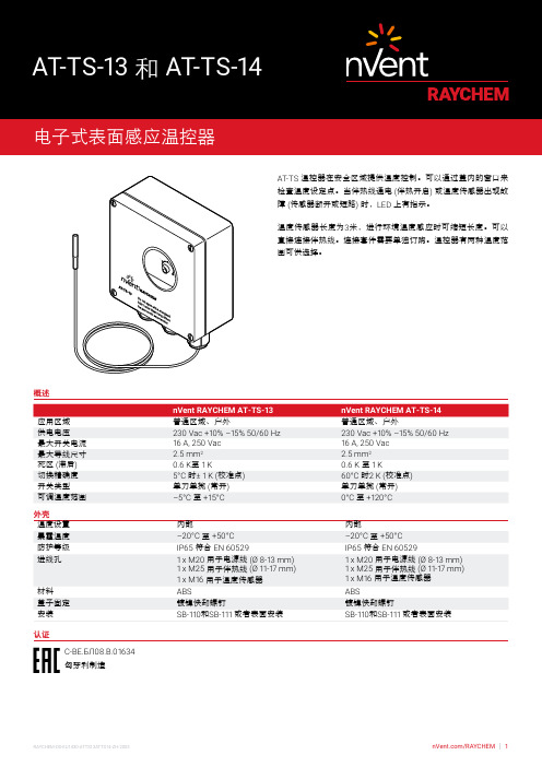
13 14
AT-TS 温控器在安全区域提供温度控制。
可以通过盖内的窗口来检查温度设定点。
当伴热线通电 (伴热开启) 或温度传感器出现故障 (传感器断开或短路) 时,LED 上有指示。
温度传感器长度为3米,进行环境温度感应时可缩短长度。
可以直接连接伴热线。
连接套件需要单独订购。
温控器有两种温度范围可供选择。
概述
nVent RAYCHEM AT-TS-13nVent RAYCHEM AT-TS-14应用区域普通区域、户外
普通区域、户外
认证
С-ВЕ.БЛ08.В.01634匈牙利制造
尺寸 (MM)
A 绿色 LED 伴热线接通
B 红色 LED 传感器断开
C 红色 LE
D 传感器短路
温度传感器
AT-TS-13AT-TS-14
类型PTC KTY 83-110PTC KTY 83-110 ()133571-000 (180 g)133571-000 (180 g)
温控器AT-TS-13或AT-TS-14接线图
AT-TS-13/14直接连接
自调控伴热线
AT-TS-13/14,连接接触器
自调控伴热线
* 根据当地条件、标准和条例,有可能需要用断路器作二极或四极电气防护。
** 根据应用情况,可以采用单极或三极断路器或接触器。
*** 选装:零电势断路器,用来连接BMS。
TS-9101-8104
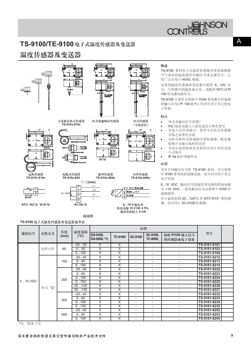
2 3 4
NTC “K2”त “K10”႙
Pt-100 ႙
0…10 V ႙! ࠃۉۉᇸ! 15 V DC ± 5%, ࢁፌ!ٷ 2 mA
ᇍѢ⏽ᑺ㣗ೈ20…120°C ⱘNTC”K10” ൟӴᛳ ఼ˈҙৃ⫼Ѣ SC-9100 ࠊ఼DŽ
থ! ၍! ! TS-9100 !ۉ ጱ! ๕! ࿒! !܈ !د ߌ! ഗ! त! Վ! ໃ! ഗ! ! ႙! ! ! ! ႑! ࡽ! Ҿ! ጎ! !ݛ ๕! ! !܈ (mm) ࿒! !܈ !ݔ ྷ! DX-9100, (°C) DX-9200, *1) -40…50 0…40 0...100 -20...40 0...40 0...100 -20...40 0...40 0...100 0...150 20…120 50…150 -20...4040 0...40 0...100 X X X X X X X X X X X X X X X X X X X ᆌ! ᆩ! TC-9100 X X X X X X X X X X X X X X X X X X X SC-9100 SC-9100, TC-8900, থ! ! Pt100 ! ! ႑! ࡽ! !ڦ ੦! ! ഗ! ई! !ۉ ጱ! ย! Ԣ! ႙! ࡽ! TS-9101-8101 TS-9101-8103 TS-9101-8104 TS-9101-8212 TS-9101-8213 TS-9101-8214 TS-9101-8222 TS-9101-8223 TS-9101-8224 TS-9101-8225 TS-9101-8226 TS-9101-8227 TS-9101-8232 TS-9101-8233 TS-9101-8234 TS-9101-8235 TS-9101-8252 TS-9101-8253 TS-9101-8254
TS系列温度传感器简介
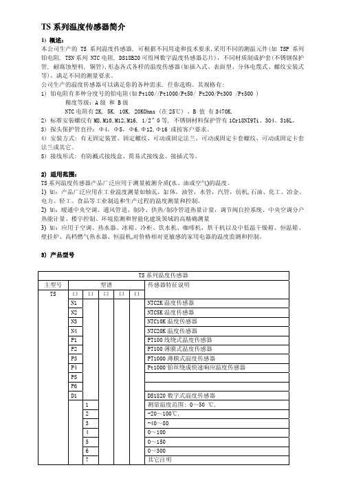
2
SUS304
3
SUS316L,
4
铜管 H62
1 传感器引线制 采用 2 线
2 采用 3 线
3 采用 4 线
注: TS 温度传感器 量程 0~200℃, 则型号为:TSP1-2-P1-1 (0~200℃)
4) 主要特征: A) TSP 系列温度传感器全部产品采用陶瓷薄膜铂电阻芯片或线绕式铂电阻芯片和精密加工件装配而 成。耐振动、耐高温、稳定性好、精度高,外形美观大方。由线绕式铂电阻芯片制成的快速响应温度 传感器其感温元件 Pt1000 由直径大约 40μm 的铂丝绕成的线圈用两层聚酰亚胺箔绝缘,热容量非常 小,这种传感器具有极佳的快速响应。
精度等级:A 级 和 B 级 NTC 电阻有 2K, 5K, 10K, 20KOhms (在 25℃) 。B 值 有 3470K, 2) 标准安装螺纹有 M8,M10,M12,M16, 1/2”G 等, 不锈钢材料保护管有 1Cr18NI9Ti、304、316L。 3) 探头保护管直径:Φ4,Φ5,Φ6,Φ12,Φ16 或按客户要求。 4) 安装方式: 有无固定装置、固定螺纹、可动或固定法兰、可动或固定卡套螺纹、可动或固定卡套 法兰或其它。 5) 接线形式: 有防溅式接线盒、简易式接线盒、接插式等。
各种负温度系数 NTC 热敏电阻-温度传感器技术参数详解与选型

DTV Series -- Die (Bare Chip) NTC Thermistor for Vehicle Temperature Sensor & Thermo Switch Making
DTM 系列——醫療溫度感測器用 NTC 熱敏晶片
DTM Series -- Die (Bare Chip) NTC Thermistor for Medical Temperature Sensor Making
4. 通讯: CT系列——片式负温度系数热敏电阻 AT系列——非绝缘引线插件 NTC热敏电阻
5. 计算机及办公自动化设备: OT系列——办公自动化NTC热敏电阻/温度传感器 GT系列——玻璃封装NTC热敏电阻 FT系列——薄膜NTC热敏电阻
6. 消费类电子: PT系列——功率型(浪涌抑制)NTC热敏电阻 AT系列——非绝缘引线插件 NTC热敏电阻 BT系列——绝缘引线型NTC温度传感器
1、 零功率電阻值 RT Zero-power resistance (RT)
在規定溫度下,採用引起電阻變化相對於總的測量誤差來說可以忽略不計的測量功率測得的電阻值。 The zero-power resistance is the value of a resistance when measured at a specified temperature, under conditions such that the change in resistance due to the internal generation of heat is negligible with respect to the total error of measurement.
- 1、下载文档前请自行甄别文档内容的完整性,平台不提供额外的编辑、内容补充、找答案等附加服务。
- 2、"仅部分预览"的文档,不可在线预览部分如存在完整性等问题,可反馈申请退款(可完整预览的文档不适用该条件!)。
- 3、如文档侵犯您的权益,请联系客服反馈,我们会尽快为您处理(人工客服工作时间:9:00-18:30)。
精度 A级 B级
允许偏差(℃) +/- (0.15+0.002∣t∣) +/- (0.3+0.005∣t∣)
C) TSN 系列温度传感器将高精度、高可靠的 NTC 热敏电阻器与 PVC 导线连接,用绝缘、导热、防水 材料封装成所需要的形状,便于安装与远距离测控温。 采用全新工艺、产品性能稳定,可长期工作。(年电阻值漂移率点 1) 电阻值和 B 值精度高、一致性好、可互换。(电阻值和 B 值精度分别可达±1%) 灵敏度高、反应迅速。(电阻温度系数可达-(2~5)%/) 采用双层密封工艺,具有良好的绝缘密封性和抗机械碰撞、抗折弯能力、可靠性高。 可根据使用的安装条件封装,便于用户安装。 可制成高耗散产品,测试电流可大大高于传统结构的传感器,简化线路 用热敏电阻器制作的 TSN 温度传感器,在较窄的温度范围内检测灵敏度高,在微小温度差的测量方面 极其有用,广泛应用于家用空调、汽车空调、冰箱、冷柜、热水器、饮水机、暖风机、洗碗机、消毒 柜、洗衣机、烘干机以及中低温干燥箱、恒温箱等场合的温度测量与控制。
B) TSD 系列数字温度传感器,采用美国 DALLAS 公司生产的 DS18B20 可组网数字温度传感器芯片,经 焊接,外加不锈钢保护管封装而成,具有耐磨耐碰,体积小,使用方便,封装形式多样,适用于各种 狭小空间设备数字测温和控制领域。独特的单线接口方式,DS1820 在与微处理器连接时仅需要一条 口线即可实现微处理器与 DS1820 的双向通讯, 数字温度传感器都具有唯一的编号,温度采集设备通 过编号来识别对应的温度传感器。支持“一线总线”接口(1-Wire)。
DS1820 数字式温度传感器 测量温度范围: 0~50 ℃, -20~100℃, -40~80 0~100 0~150 0~300 其它注明
B1
外壳编号及安装方式: 表面贴装(标准外壳编号)
P1
探头插入 螺纹安装(标准外壳编号)
H1
探头插入 (HANG)悬挂安装
1
外壳材质 1Cr18NI9Ti(SUS301)
2
SUS304
3
SUS31线制 采用 2 线
2 采用 3 线
3 采用 4 线
注: TS 温度传感器 量程 0~200℃, 则型号为:TSP1-2-P1-1 (0~200℃)
4) 主要特征: A) TSP 系列温度传感器全部产品采用陶瓷薄膜铂电阻芯片或线绕式铂电阻芯片和精密加工件装配而 成。耐振动、耐高温、稳定性好、精度高,外形美观大方。由线绕式铂电阻芯片制成的快速响应温度 传感器其感温元件 Pt1000 由直径大约 40μm 的铂丝绕成的线圈用两层聚酰亚胺箔绝缘,热容量非常 小,这种传感器具有极佳的快速响应。
5) 主要技术参数 TSN 温度传感器 典型规格主要技术参数: 环境温度:0~85℃ 相对湿度:5~90%RH 在 40℃下 (无凝露) 基本误差:±0.2% ±0.5% ±1% 环境温度变化影响:
TSP 温度传感器 典型规格主要技术参数: 测量温度范围:-40…500℃, 测量常规温度范围: -20-150℃ 探头结构: 如插入式、表面型、分体电缆式、螺纹安装式等 测量探套:壁厚 0.3mm 到 1. 0mm, 长从 20mm 到 300mm
TS 系列温度传感器简介
1) 概述: 本公司生产的 TS 系列温度传感器, 可根据不同用途和技术要求,采用不同的测温元件(如 TSP 系列 铂电阻, TSN 系列 NTC 电阻, DS18B20 可组网数字温度传感器芯片),不同材质制成护套(不锈钢保护 管, 耐腐蚀塑料, 铜管),形态各式各样的温度传感器(如插入式、表面型、分体电缆式、螺纹安装式 等),满足不同的测量要求。 公司生产的温度传感器可以满足你的各种需求, 任你选购。其规格有: 1) 铂电阻有多种分度号的铂电阻(如 Pt100//Pt1000/Pt50/ Pt200/Pt300 /Pt500 )
精度等级:A 级 和 B 级 NTC 电阻有 2K, 5K, 10K, 20KOhms (在 25℃) 。B 值 有 3470K, 2) 标准安装螺纹有 M8,M10,M12,M16, 1/2”G 等, 不锈钢材料保护管有 1Cr18NI9Ti、304、316L。 3) 探头保护管直径:Φ4,Φ5,Φ6,Φ12,Φ16 或按客户要求。 4) 安装方式: 有无固定装置、固定螺纹、可动或固定法兰、可动或固定卡套螺纹、可动或固定卡套 法兰或其它。 5) 接线形式: 有防溅式接线盒、简易式接线盒、接插式等。
探套材质:1Cr18NI9Ti 或 SUS316L 不锈钢管 自带导线长度:1 米、2 米、3 米、5 米、10 米或带接线盒 输出信号:单组、双组,2 线制,3 线制,4 线制 传感器类型: Pt 100 R0=100Ω@0℃; 电阻温度系数 0.00385/℃
Pt 1000 R0=1000Ω@0℃ 电阻温度系数 0.00375/℃ Pt 100 精度
3) 产品型号
主型号 TS
型谱 口口口口 N1 N2 N3 N4 P1 P2 P3 P4 P5 P6 D1
1 2 3 4 5 6 7
TS 系列温度传感器 传感器特征说明
口 NTC2K 温度传感器 NTC5K 温度传感器 NTC10K 温度传感器 NTC20K 温度传感器 PT100 线绕式温度传感器 PT100 薄膜式温度传感器 PT1000 薄膜式温度传感器 Pt1000 铂丝绕成快速响应温度传感器
2) 适用范围: TS 系列温度传感器产品广泛应用于测量被测介质(水、油或空气)的温度。 1) 如:产品广泛应用在工业温度测量如轴瓦,缸体,油管,水管,汽管,纺机,石油、化工、冶金、 电力、轻工、食品等工业制造和生产过程的温度测量和控制。 2) 如:暖通中央空调、通风管道、制冷、供热/制冷管道热量计量,调节阀自控系统、中央空调分户 热能计量、楼宇控制、环境监测和智能化建筑领域的高精确测量 3) 如:应用于空调、热水器、冰箱、冷柜、饮水机、咖啡机,烘干机以及中低温干燥箱、恒温箱、 壁挂炉、高档燃气热水器、恒温机,对价格相对更敏感的家用电器的温度监测和控制。
