松下神视光电说明
Panasonic EX-10 Series 内部超瘦光电感应传感器说明书

Thank you very much for purchasing Panasonic products. Read this Instruction Manual carefully and thoroughly for the correct and optimum use of this product. Kindly keep this manual in a convenient place for quick reference. ●Please refer “our web site (/id/pidsx/global)”.●Access method is “Download ” → “Manual ”→ “Model No.”. ●If you could not visit our web site, contact our sales office near your sight.12MOUNTING●The tightening torque should be 0.2N∙m or less.(Unit: mm)3WIRING DIAGRAMSNotes: 1) Thru-beam with operation mode switch on bifurcation is not prepared.2) The thru-beam type sensor emitter does not incorporate the output (black).4CAUTIONS●This product has been developed / produced for indus-trial use only.●For the convergent reflective type EX-14□, if there is a reflective object (e.g., a conveyor, etc.) in the background of the sensing object, since it may affect the sensing, use by keeping enough distance from the reflective object.●The thin cable 0.1mm 2 is used for this product. Thus,take care that if the cable is pulled with excessive force, it may cause cable break.●Extension up to total 50m (each emitter and receiver of thru-beam type), or less, is possible with 0.3mm 2, or more of conductor area cable. However , the extension of a power supply line and the output line of less than 10m is acceptable in case using this product as conform-ing to S-mark.●Make sure to carry out wiring in the power supply OFF condition.●Take care that wrong wiring will damage the sensor.●Verify that the supply voltage variation is within the rating.●If power is supplied from a commercial switching regu-lator, ensure that the frame ground (F.G.) terminal of the power supply is connected to an actual ground.●In case noise generating equipment (switching regulator, inverter motor, etc.) is used in the vicinity of this product, connect the frame ground (F.G.) terminal of the equipment to an actual ground.●Do not run the wires together with high-voltage lines or power lines or put them in the same raceway. This can cause malfunction due to induction.●Take care that the sensor is not directly exposed to fluorescent lamp from a rapid-starter lamp, a high frequency lighting de-vice or sunlight etc., as it may affect the sensing performance.●Do not use during the initial transient time (EX-15□, EX-15E □, EX-17□, EX-17E □: 100ms, others: 50ms) after the power sup-ply is switched ON.●This sensor is suitable for indoor use only.●Do not use this sensor in places having excessive vapor, dust, etc., or where it may come in contact with corrosive gas, etc.●Take care that the sensor does not come in contact with oil, grease, organic solvents such as thinner, etc., strong acid, or alkaline.●This sensor cannot be used in an environment contain-ing inflammable or explosive gases.●Never disassemble or modify the sensor.●Since the cable end is not waterproof, do not use the sensor in the application where water may seep in from the cable end.5INTENDED PRODUCTS FOR CE MARKING6RoHS DIRECTIVE●This equipment complies with RoHS (EC and Chinese directive).●Chinese RoHS indicates inclusion despite regulation value. (Refer to Chinese part.)<Side sensing><Front sensing> ●NPN output type±10%±10%●PNP output type (Note 1)/id/pidsx/globalOverseas Sales Division (Head Office)2431-1 Ushiyama-cho, Kasugai-shi, Aichi, 486-0901, Japan Phone: +81-568-33-7861 FAX: +81-568-33-8591For sales network, please visit our website.© Panasonic Industrial Devices SUNX Co., Ltd. 2016PRINTED IN JAPAN●The models listed under “SPECIFICATIONS” come with CE Marking. As for all other models, please contact our office.Contact for CEPanasonic Marketing Europe GmbH Panasonic T esting Center Winsbergring 15, 22525 Hamburg,Germany056 222 38 18*********************SEN TRONIC AG。
Panasonic 22 Polarity Mark Infrared LED 说明书

Dimensions: [mm]1Scale - 10:115412085A900015412085A900015412085A900015412085A900015412085A9000T e m p e r a t u r eT pT L15412085A9000Cautions and Warnings:The following conditions apply to all goods within the product series of Optoelectronic Components of Würth Elektronik eiSos GmbH & Co. KG:General:•This optoelectronic component is designed and manufactured for use in general electronic equipment.•Würth Elektronik must be asked for written approval (following the PPAP procedure) before incorporating the components into any equipment in fields such as military, aerospace, aviation, nuclear control, submarine, transportation (automotive control, train control, ship control), transportation signal, disaster prevention, medical, public information network, etc. where higher safety and reliability are especially required and/or if there is the possibility of direct damage or human injury.•Optoelectronic components that will be used in safety-critical or high-reliability applications, should be pre-evaluated by the customer.•The optoelectronic component is designed and manufactured to be used within the datasheet specified values. If the usage and operation conditions specified in the datasheet are not met, the wire insulation may be damaged or dissolved.•Do not drop or impact the components, the component may be damaged•Würth Elektronik products are qualified according to international standards, which are listed in each product reliability report. Würth Elektronik does not warrant any customer qualified product characteristics beyond Würth Elektroniks’ specifications, for its validity and sustainability over time.•The responsibility for the applicability of the customer specific products and use in a particular customer design is always within the authority of the customer. All technical specifications for standard products also apply to customer specific products.•Unless Würth Elektroik has given its express consent, the customer is under no circumstances entitled to reverse engineer, disassemble or otherwise attempt to extract knowledge or design information from the optoelectronic componentProduct specific:Soldering:•The solder profile must comply with the technical product specifications. All other profiles will void the warranty.•All other soldering methods are at the customers’ own risk.•The soldering pad pattern shown above is a general recommendation for the easy assembly of optoelectronic component. If a high degree of precision is required for the selected application (i.e. high density assembly), the customer must ensure that the soldering pad pattern is optimized accordingly.Cleaning and Washing:•Washing agents used during the production to clean the customer application might damage or change the characteristics of the optoelectronic component body, marking or plating. Washing agents may have a negative effect on the long-term functionality of the product.•Using a brush during the cleaning process may break the optoelectronic component body. Therefore, we do not recommend using a brush during the PCB cleaning process.Potting:• If the product is potted in the customer application, the potting material might shrink or expand during and after hardening. Shrinking could lead to an incomplete seal, allowing contaminants into the optoelectronic component body, pins or termination. Expansion could damage the components. We recommend a manual inspection after potting to avoid these effects.Storage Conditions:• A storage of Würth Elektronik products for longer than 12 months is not recommended. Within other effects, the terminals may suffer degradation, resulting in bad solderability. Therefore, all products shall be used within the period of 12 months based on the day of shipment.•Do not expose the optoelectronic component to direct sunlight.•The storage conditions in the original packaging are defined according to DIN EN 61760-2.•For a moisture sensitive component, the storage condition in the original packaging is defined according to IPC/JEDEC-J-STD-033. It is also recommended to return the optoelectronic component to the original moisture proof bag and reseal the moisture proof bag again.•The storage conditions stated in the original packaging apply to the storage time and not to the transportation time of the components. Packaging:•The packaging specifications apply only to purchase orders comprising whole packaging units. If the ordered quantity exceeds or is lower than the specified packaging unit, packaging in accordance with the packaging specifications cannot be ensured. Handling:•Violation of the technical product specifications such as exceeding the nominal rated current, will void the warranty.•The product design may influence the automatic optical inspection.•Certain optoelectronic component surfaces consist of soft material. Pressure on the top surface has to be handled carefully to prevent negative influence to the function and reliability of the optoelectronic components.•ESD prevention methods need to be applied for manual handling and processing by machinery.•Resistors for protection are obligatory.•Luminaires in operation may harm human vision or skin on a photo-biological level. Therefore direct light impact shall be avoided.•In addition to optoelectronic components testing, products incorporating these devices have to comply with the safety precautions given in IEC 60825-1, IEC 62471 and IEC 62778•Please be aware that Products provided in bulk packaging may get bent and might lead to derivations from the mechanicalmanufacturing tolerances mentioned in our datasheet, which is not considered to be a material defect.Würth Elektronik eiSos GmbH & Co. KGEMC & Inductive SolutionsMax-Eyth-Str. 174638 WaldenburgGermanyCHECKED REVISION DATE (YYYY-MM-DD)GENERAL TOLERANCE PROJECTIONMETHODZAn001.0012021-03-15DIN ISO 2768-1mDESCRIPTIONWL-SICW SMT Infrared Chip LEDWaterclear ORDER CODE15412085A9000SIZE/TYPE BUSINESS UNIT STATUS PAGETechnical specification:•The typical and/or calculated values and graphics of technical parameters can only reflect statistical figures. The actual parameters of each single product, may differ from the typical and/or calculated values or the typical characteristic line.•On each reel, only one bin is sorted and taped. The bin is defined on intensity, chromaticity coordinate or wavelength and forward voltage.•In order to ensure highest availability, the reel binning of standard deliveries can vary. A single bin cannot be ordered. Please contact us in advance, if you need a particular bin sorting before placing your order.•Test conditions are measured at the typical current with pulse duration < 30ms. •Optical properties are measured according the CIE 127:2007 standard.•Wavelength tolerance under measurement conditions ± 2nm.•Optical intensity tolerance under measurement conditions ±15%.•Forward voltage tolerance under measurement conditions ± 0.1V.•CCT tolerance of x and y coordinate of ± 0.01and CRI tolerance of ± 2 is allowed In the characteristics curves, all values given in dotted lines may show a higher deviation than the parameters mentioned above.These cautions and warnings comply with the state of the scientific and technical knowledge and are believed to be accurate and reliable.However, no responsibility is assumed for inaccuracies or incompleteness.The customer has the sole responsibility to ensure that he uses the latest version of this datasheet, which is available on Würth Elektronik’s homepage. Unless otherwise agreed in writing (i.e. customer specific specification), changes to the content of this datasheet may occurwithout notice, provided that the changes do not have a significant effect on the usability of the optoelectronic componentsWürth Elektronik eiSos GmbH & Co. KG EMC & Inductive Solutions Max-Eyth-Str. 174638 Waldenburg GermanyCHECKED REVISION DATE (YYYY-MM-DD)GENERAL TOLERANCEPROJECTION METHODZAn001.0012021-03-15DIN ISO 2768-1mDESCRIPTIONWL-SICW SMT Infrared Chip LED WaterclearORDER CODE15412085A9000SIZE/TYPEBUSINESS UNITSTATUSPAGEImportant NotesThe following conditions apply to all goods within the product range of Würth Elektronik eiSos GmbH & Co. KG:1. General Customer ResponsibilitySome goods within the product range of Würth Elektronik eiSos GmbH & Co. KG contain statements regarding general suitability for certain application areas. These statements about suitability are based on our knowledge and experience of typical requirements concerning the areas, serve as general guidance and cannot be estimated as binding statements about the suitability for a customer application. The responsibility for the applicability and use in a particular customer design is always solely within the authority of the customer. Due to this fact it is up to the customer to evaluate, where appropriate to investigate and decide whether the device with the specific product characteristics described in the product specification is valid and suitable for the respective customer application or not.2. Customer Responsibility related to Specific, in particular Safety-Relevant ApplicationsIt has to be clearly pointed out that the possibility of a malfunction of electronic components or failure before the end of the usual lifetime cannot be completely eliminated in the current state of the art, even if the products are operated within the range of the specifications.In certain customer applications requiring a very high level of safety and especially in customer applications in which the malfunction or failure of an electronic component could endanger human life or health it must be ensured by most advanced technological aid of suitable design of the customer application that no injury or damage is caused to third parties in the event of malfunction or failure of an electronic component. Therefore, customer is cautioned to verify that data sheets are current before placing orders. The current data sheets can be downloaded at .3. Best Care and AttentionAny product-specific notes, cautions and warnings must be strictly observed. Any disregard will result in the loss of warranty.4. Customer Support for Product SpecificationsSome products within the product range may contain substances which are subject to restrictions in certain jurisdictions in order to serve specific technical requirements. Necessary information is available on request. In this case the field sales engineer or the internal sales person in charge should be contacted who will be happy to support in this matter.5. Product R&DDue to constant product improvement product specifications may change from time to time. As a standard reporting procedure of the Product Change Notification (PCN) according to the JEDEC-Standard inform about minor and major changes. In case of further queries regarding the PCN, the field sales engineer or the internal sales person in charge should be contacted. The basic responsibility of the customer as per Section 1 and 2 remains unaffected.6. Product Life CycleDue to technical progress and economical evaluation we also reserve the right to discontinue production and delivery of products. As a standard reporting procedure of the Product Termination Notification (PTN) according to the JEDEC-Standard we will inform at an early stage about inevitable product discontinuance. According to this we cannot guarantee that all products within our product range will always be available. Therefore it needs to be verified with the field sales engineer or the internal sales person in charge about the current product availability expectancy before or when the product for application design-in disposal is considered. The approach named above does not apply in the case of individual agreements deviating from the foregoing for customer-specific products.7. Property RightsAll the rights for contractual products produced by Würth Elektronik eiSos GmbH & Co. KG on the basis of ideas, development contracts as well as models or templates that are subject to copyright, patent or commercial protection supplied to the customer will remain with Würth Elektronik eiSos GmbH & Co. KG. Würth Elektronik eiSos GmbH & Co. KG does not warrant or represent that any license, either expressed or implied, is granted under any patent right, copyright, mask work right, or other intellectual property right relating to any combination, application, or process in which Würth Elektronik eiSos GmbH & Co. KG components or services are used.8. General Terms and ConditionsUnless otherwise agreed in individual contracts, all orders are subject to the current version of the “General Terms and Conditions of Würth Elektronik eiSos Group”, last version available at .Würth Elektronik eiSos GmbH & Co. KGEMC & Inductive SolutionsMax-Eyth-Str. 174638 WaldenburgGermanyCHECKED REVISION DATE (YYYY-MM-DD)GENERAL TOLERANCE PROJECTIONMETHODZAn001.0012021-03-15DIN ISO 2768-1mDESCRIPTIONWL-SICW SMT Infrared Chip LEDWaterclear ORDER CODE15412085A9000SIZE/TYPE BUSINESS UNIT STATUS PAGE。
SUNX传感器LX-101使用说明_图文.
SUNX 传感器 LX-101 使用说明更多更多 >>松下sunx神视传感器接近传感器传感器使用sunx传感器称重传感器收藏人:Loooog接近传感器神视传感器称重传感器加速度传感器传感器精油的使用方法松下sunx最新文章这真的是爱情的坟墓吗爱情,是什么!一个老师写的,太对了! 进来看看吧!我老公没在家 ······中医舌诊无师自通丝网型号的表示方法如何在 PC 上安装 Mac OS X正品雅戈尔休闲裤男春装新款中年商务男裤热门文章中国有非常多的经典俗话,两两配对放 ... 十年精湛对唱 12首怎样卸载手机自带软件民间神方:白血病不要等,苣荬菜见神 ... 《让人才死心塌地追随您》医院笑话(暴笑专家教你 12个 " 点菜绝活 "简单易学的蒸菜做法—好吃又营养痔疮特效秘方,吐血奉献名医秘方:三年肥胖症两月根治温中健 ... 美国二战经典历史 / 战争电影【诺曼底 ... 人际交往简单的二十八招温湿度传感器传感器婚纱照自动门电线EGE 光电传感器玻璃钢电缆桥架自动门理财温湿度传感器生产厂家 , 专注高温 ... 能满足多方面的色标检测需求!具有多种最先进的色标检测功能,可根据用途选择检测模式。
具有45μs超高速反应的“ 色标模式” 和色标辨别性能最先进的“ 彩色模式” ,用户可根据需求选择使用。
色标模式是利用三种 (R·G·BLED中的一种 (单色 ,实现45μs的超高速反应的检测模式。
通过最佳 LED 自动选择功能可自动选择最佳的 LED 。
最适于高速检测。
最佳 LED 自动选择功能可从 R·G·B LED三种颜色中选择最佳的颜色搭配。
LX-100的色标模式装备了“ 最佳 LED 自动选择功能” ,以自动选择将色标和底色对比 (S/N比最大的 LED ,进行最佳检测。
松下电器Panasonic TH-L32C3C Television Manual说明书

切勿將電視機置於陽光直射以及其它熱源 之處 ●●避免將電視機置於陽光直射以及其它熱源之
處。
將蠟燭或其它明火遠離此 產品以避免火蔓延
切勿將異物放入本機中 ●●切勿使任何異物通過通風口掉入電視機
中。(可能引起火災或觸電。)
切勿將電視機放置在傾斜或不穩定之處 ●●電視機可能跌落或翻倒。
只能使用Panasonic專用底座安裝 / 安裝 設備 ●●使用未經授權的底座或其它固定設備會使
Panasonic 顧客咨詢服務中心。 當您重新安裝時,確保每個螺絲都擰緊了。 ●●如果安裝過程中未能確保螺絲正確擰緊,底座將不能支撐電視機並可能翻倒損壞或造成人身
傷害。 確保電視機不會翻倒。 ●●如果電視機被撞擊或兒童爬上裝有電視機的底座,電視機可能翻倒並造成人身傷害。 安裝或移動電視機至少需要兩個人。 ●●如果不足兩人,電視機將可能跌落造成人身傷害。
開
鉤簧
關閉
注意極性正確(+ 或 -)
注意
●●电池安装不当会造成电解液泄漏及电池腐
蚀,损坏遥控器。
●●切勿混用新旧电池。 ●●切勿混用不同类型的电池(示例:“碱性”
和“锰”电池)。
●●切勿使用充电电池(镍镉)。 ●●切勿燃烧或毁坏电池。 ●●切勿将电池放置在阳光直射、火焰或其它高
4
注意
清潔電視機時,將電源插頭拔下
●●清潔帶電的電視機會引起觸電。
日本Panasonic公司的网络摄像头说明书

Network camera exceeding the human eye featured by Super Dynamic III Key FeaturesStandard Accessories• CD-ROM*.......................................1 pc.• Installation Guide...........................1 pc.* The IP setup software, the viewer softwareand the network operating instructions(PDF) are included on the CD-ROM.The following are for installation.• Mount Bracket (w/safety wire)........ 1 pc.• Fixing Screw .................... 2 pcs. (incl. a spare screw)• Decorative Cover.......................... 1 pc.• DC 12 V Power Cord Plug............ 1 pc.• Code Label*.................................. 1 pc.* It will be needed for network management.A network administrator should keep this label.• Built-in MPEG-4 and JPEG digital signal output at VGA image size with up to 30 ips.• MPEG-4/JPEG dual stream output for simultaneous live monitoring and high resolution recording.• Progressive Output with motion adaptive interlace/progressive conversion allows every frame to be clear even when the object is moving.• Super Dynamic III technology delivers 128x wider dynamic range compared to conventional cameras.• High sensitivity: Color: 0.7 lux (Sens up OFF), B/W: 0.5 lux (Sens up OFF)• Simple Day-Night function (No IR cut filter moving)• Up to 32x automatic electronic sensitivity enhancement.• Video Motion Detector with 4 programmable detection areas and 3 sensitivity levels.• 22x zoom lens with 10x digital zoom enabling 220x zoom• Auto tracking: Pan and tilt automatically controlled to keep moving objects centered in screen.• PTZ control can be taken on the user friendly GUI with 16 speeds pan/tilt and new “Drag and Zoom” operation enabling finer control. 256 speeds available for system with WV-CU950 system controller. • Up to 64 preset positions• 360 map shot: 8 thumbnail images at 45 deg. intervals make it simple to direct the camera easily by clicking on a thumbnail.• Built-in network interface (10Base-T / 100Base-TX).• Power over Ethernet (PoE) IEEE 802.3af.• Multiscreen: Image from 16 cameras can be displayed in 4 different Quad screens or 16-screen (JPEG only)• FTP client function enables periodic image data transfer or transfer upon alarm • Alarm notification via E-mail.• Max. bit rate/client for MPEG-4 (64 / 128 / 256 / 512 / 1,024 / 2,048 / 4,096 kbps) and Total bit rate control (64 / 128 / 256 / 512 / 1,024 / 2,048 / 4,096 kbps / Unlimited) allowing flexible network management.• 2-way audio feature (G.726, 32 / 16 kbps)• Alarm log, Manual REC log, FTP error log saved in the SD card is displayed on the browser GUI and can be downloaded to the client PC. Playback or Image data download through the log is also available. • Multi-language GUI and setup menu: English, French, Italian, Spanish, German, Polish, Russian (PAL), English, French (NTSC), (Installation required except for English).• SD Memory card slot for Manual recording, Alarm recording and Backup upon network failure.• Alarm sources include Terminal 1 ~ 3, VMD and Panasonic alarm command. Selectable alarm actions include SD memory recording, FTP image transfer, E-mail notification, Alarm indication, Terminal output, Camera positioning, Auto track and Panasonic protocol output.• Scheduling function for Alarm / VMD / Access permission, Preset position call and Position refresh.• Industrial grade Pan/Tilt/Zoom mechanism for high reliability• One-touch Fitting Mechanism for easy installation• Desktop/Ceiling position choice and various optional brackets for versatile installationsSuper Dynamic IIIDome Network CameraWV-NS202A WV-NS202A (12V DC or PoE) (12V DC or PoE)Optional AccessoriesCeiling Mount BracketsWV-Q152C (Clear)WV-Q152S (Smoke)Inner Dome CoverWV-Q153Wall Mount BracketsWV-Q150C (Clear)WV-Q150S (Smoke)Direct Ceiling InstallationWV-Q105(Smoke Type)(Smoke Type)(Smoke Type)Embedded Ceiling Mount BracketsWV-Q151C (Clear)WV-Q151S(Smoke)Trademarks and registered trademarks– Microsoft, and Windows are registered trademarks of Microsoft Corporation in the U.S. and other countries.– SD logo is a trademark. Important– Safety Precaution: carefully read the operating instructions and installation manual before using this product.– Panasonic can not be responsible for network performance and/or other manufacturer products that reside on the network.DISTRIBUTED BY:Panasonic is the brandname of Matsushita Electric.Printed in Japan(2A-003L)SpecificationsTV System NTSC PALCamera Image Sensor1/4-type interline transfer CCD, Effective pixeles: 768 (H) x 494 (V), Scanning Area: 3.59 (H) x 2.70 (V) mmScanning Mode 2:1 interlace scan (with motion adaptive interlace/progressive conversion)Minimum Illumination Color (30 IRE): 0.7 lux (Sen up: OFF), 0.02 lux (Sens up: 32x) at F1.6B/W (10 IRE): 0.5 lux (Sens up: OFF), 0.015 lux (Sens up: 32x) at F1.6White Balance AWC (2,000 ~ 10,000 K), ATW1 (2,700 ~ 6,000 K), ATW2 (2,000 ~ 6,000 K)Light Control Automatic integration of ALC/ELC AGC ON (LOW) / ON (MID) / ON (HIGH) / OFF Super Dynamic III ON or OFF (with BLC masking)Dynamic Range 52 dB typical (Super Dynamic III : ON, Shutter speed: OFF)Electronic Shutter OFF (1/60), AUTO, 1/100Electronic Sensitivity UP OFF / AUTO (2x, 4x, 6x, 10x, 16x, 32x)Digital Noise Reduction High / LowBlack and White Mode OFF / Auto (No IR moving)Video Motion Detector For preset position: 4 programable detection areas, Sensitivity: 6 stepsNon-preset position: Detects entire screen except clock area, Sensitivity: 6 stepsPrivacy Zone Up to 8 zones, Gray/Mosaic Up Side Down ON (desktop) / OFF (ceiling)Camera Title Up to 16 characters (alphanumeric characters, marks)Lens Type22x (3.79 mm ~ 83.4 mm) Zoom lens, 220x with 10x digital zoom. F: 1:1.6 (WIDE) ~ 3.0 (TELE)Angular Field of View H: 2.6° (TELE) ~ 51.7° (WIDE), V: 2.0° (TELE) ~ 39.9° (WIDE)Min. Object Distance 1.6 mPan and Panning Range 0° ~ 350°Tilt Panning SpeedManual: approx.1°/s ~ 100°/s, Up to 256 steps (depending on the controller) Preset: up to approx. 300°/sTilting Range –30° ~ 90° (upward-level-downward)Tilting angle limit: 0° / –5° / –10° / –15° / –20° / –25° / –30°Tilting SpeedMnual: approx. 1°/s ~ 100°/s, Up to 256 steps (depending on the controller) Preset: up to approx. 100°/sProportional Pan/Tilt Control Yes Number of Preset Positions 64Auto Mode OFF/ preset sequence / auto pan / auto track Image Hold ON / OFF PTZ Position Display ON / OFF Map Shot 360° map shot / preset map shotBrowser Camera Control Pan/Tilt (16 steps), Zoom, Focus, Click centering, Drag zoom, GUI Iris, Preset position call and program, Auto mode.Display ModeImage from 16 cameras can be displayed in 4 different Quad screens or 16-screen (JPEG only). 20 characters camera title available.SD Memory Data Download Images recorded in the SD memory card can be downloaded.Clock DisplayTime: 12H/24H, Date: 5 formats on the browser, Summer time (Manual)GU I /Setup English, French English, French, Italian, Spanish, German, Polish,Menu Language (Installation required for French)Russian (Installation required except for English.)System Log Alarm log, Manual REC log, FTP error log (SD memory required) Supported OS Microsoft Windows ® 2000 Professional SP4, Microsoft Windows ® XPProfessional/Home SP2 English, French, Italian, Spanish, GermanSupported Browser Internet Explorer 7.0 Internet Explorer 6.0 SP2 (Windows ® XP Home/Professional SP2)Internet Explorer 6.0 SP1 (Only Windows ® 2000 Professional SP4)Network Network IF 10Base-T / 100Base-TX, RJ45 connectorImage Resolution VGA (640 x 480) / QVGA (320 x 240)Image CompressionMPEG-4: Image quality: LOW/NORMAL/FINE, Transmission type: UNICAST/MULTICAST JPEG: Image quality: 10 steps, Transmission type: PULL/PUSH Image Refresh Rate0.1 / 0.2 / 0.33 / 0.5 / 1 / 2 / 3 / 5 / 6 / 10 / 15 / 30 ips (Max. rate will be 5 ips-VGA, (JPEG)10 ips-QVGA when transmitting JPEG and MPEG-4 simultaneously)Audio Compression G.726 (ADPCM) 32 kbps/16 kbps Audio Mode OFF / Mic input / Audio output / Interactive Total Bit Rate 64 / 128 / 256 / 512 / 1,024 / 2,048 / 4,096 kbps / Unlimited Max. Bit Rate/Client (MPEG-4)64 / 128 / 256 / 512 / 1,024 / 2,048 / 4,096 kbpsSupported ProtocolTCP/IP, UDP/IP, HTTP, FTP, SMTP, DHCP, DNS, DDNS, NTP, SNMP, RTP FTP Client Alarm image transfer, Periodic image transfer No. of Simultaneous Users Up to 8 usersSD Memory Card (Option)Manual REC/Alarm REC/Backup upon network failure.Compatible SD card: Panasonic 64MB, 128MB, 256MB, 512MB, 1GB, 2GB model.SDHC standard card not supported.User Registration Up to 16 users User Level 3 Levels: Administrator, Camera control, Live onlySecurity MethodUser authentication (ID and Password), Host authentication (IP address)Alarm Alarm Source 3 x Terminal inputs, VMD, Command alarmAlarm ActionsSD memory recording, E-mail notification, Indication on browser, Camera positioning, FTP image transfer, Terminal output, Panasonic protocol output, Auto trackAlarm Log With SD memory card: 5,000 logs, Without SD memory card: 1,000 logs Schedule Alarm/VMD/Access permission, Preset position call, Position refreshInput/Monitor Output 1.0 V [p-p] / 75 Ω, 1.0 V [p-p] / 75 Ω,OutputNTSC composite, ø3.5 mm mini jack PAL composite, ø3.5 mm mini jack External I/O Terminals ALARM IN 1, ALARM IN 2/ALARM OUT, ALARM IN3/AUX OUT Microphone Input MIC IN (Applicable microphone; Plug-in power type)Supply voltage: 2.5 V ±0.5 V Input impedance: 3 K Ω ±10 %Audio OutputAUDIO OUT ø3.5 mm stereo mini jack (monaural output) Line level General Safety/EMC Standard UL 6500, C-UL (E60065),CE (EN55022 ClassB EN55024),FCC Part15 ClassA, ICES003 ClassA GOST (R 51558)Power Source/Consumption DC 12 V: approx. 1,000 mA, PoE: approx.12.0 W (IEEE802.3af compliant, Class 0 device)Ambient Operating –10 °C ~ +50 °C (14 °F ~ 122 °F), 90 % or less (without condensation)Temperature/HumidityDimensionsø115 mm x 154 mm (H) (ø4-17/32" x 6-1/16" (H)) (excluding the DC 12 V power cord plug)Weight Camera: approx. 850 g (1.87 lbs.)Accessories (Camera mounting bracket, decorative cover): approx. 200 g (0.44 lbs.)Major Operating Controls & Terminals• All TV pictures/menu are simulated.• Weights and dimensions are approximate.• Specifications are subject to change without notice.• These products may be subject to export control regulations. • Product pictures shown in this catalog are all NTSC models.。
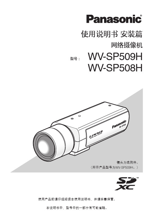
松下摄像机说明书
警告:•请勿将本产品置于雨水、潮湿的环境中,以免发生火灾或触电。
•为防止造成伤害等事故,请务必按照安装说明将本产品牢固地固定在地面、墙壁或天花板上。
•安装应当遵照本产品所适用的所有安装规则。
•本产品没有电源开关。
如需切断电源,则关闭电源装置或拔下电源线。
•连接应当符合当地的电气规定。
注意:•标示有本产品机身编号等的标签贴附于本产品的表面。
请在下面空白处填上本产品的机身编号,并将此说明书妥善保存,以便万一遭窃时查核。
型号:SER.No.(机身编号):2目录重要安全须知 (4)有限责任 (5)免责条款 (5)前言 (5)关于标记 (6)特点 (6)关于使用说明书 (7)对电脑的系统要求 (7)商标和注册商标 (8)关于著作权 (8)网络安全 (9)注意事项 (10)安装时的注意事项 (13)各部分的名称 (15)镜头安装 (17)插入和取出SD记忆卡*1 (仅WV-SP509H) (19)安装 (20)连接 (24)使用光盘 (28)配置网络设置 (31)故障排除 (33)规格 (34)附件 (38)选购件 (38)补充说明 (39)*1 SDXC/SDHC/SD记忆卡记载为SD记忆卡。
3不要损坏电源线不要损坏、加工电源线,不要使电源线靠近加热器,不要过分弯折、拧电源线,不要拉扯电源线,不要在电源线上放置很重的东西,不要绑扎电源线。
如果使用有损伤的电源线,可能会导致触电、短路或火灾。
如需修理,请委托经销商。
清洁时请切断电源否则可能导致受伤。
[使用时的注意事项]本产品仅限室内专用。
请勿在室外使用。
本产品没有电源开关切断电源时,需断开直流12 V电源或PoE设备的电源。
(同时使用直流12 V电源和PoE 设备作为电源时,两者均需断开。
)环境要求请勿长时间在高温、高湿的场所使用。
否则有可能会损坏本产品的部件从而缩短使用寿命。
请勿在靠近热源的地方(如加热器附近)使用本产品。
小心轻放本产品避免坠落、强烈冲击或振动,以免损坏产品而造成功能不良。
松下 PT-X20ST S1 液晶投影机(交互式) 说明书
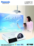
S1
液晶投影机(交互式)
) (交互式 机 影 投 适应力 的液晶 境 变 环 多 的 灵活 出色
PT-X20ST
液晶投影机(交互式)
S1
3000 lm
集人机对话、短焦优势、 互动白板功能于一身的革命性产品!
3个 “1” 人机交互对话
高灵敏度红外电子笔,在投影处直接控制电脑。 实现 1 台 PC、1 台投影机、1 支电子笔交互式 人机对话。 减少往返于幕布与黑板间的不便,拒 绝粉尘, 引领教育新变革, 成就卓越讲演!
专用通信电缆
电子笔
电子笔头套
PT-X20ST S1
PT-X20ST S1
当使用环境温度高, 或者有油烟、 烟雾时, 可能出现使用时间不满一年时, 需要更换灯泡和液晶板、 偏光板等光学部件的情况。 如果短时间内频繁开关, 或者连续 12 小时以上使用, 灯泡的更换周期 可能会缩短。 详情请询问销售代表。
广告经营者:上海联智会展服务有限公司
地址:上海市合肥路 315 号海文商务楼 5 楼
邮编:200025
发行日期 2011 年 10 月 [11ADI1001]
PT-X20ST S1
短焦显真彩
PT-X20ST S1 全面缩减光线危害 , 短程 投影, 色彩依旧。流畅教学从更少阴影开始!
出色的环境适应力
内置互动白板功能 , 多种光滑介质都可以充当 幕布 ( 例如 : 墙壁、普通黑 / 白板 )。 远离眩光, 还原清晰视界!
PT-X20ST S1
PT-UX71NT
致力于环保设计
1.3W
PT-X20STS1
交互接口
PT-X20ST S1
1.3W
3000lm 600:1
Panasonic 光电传感器产品说明书

ANLY PHOTO SENSORPHOTO SENSORTYPE SELECTION :I02PS0T30--001NProduct is subject to change without notice.SENSING MODE P=Photo type F=Optical fiber typeBODY SHAPE Q=sQuare type M=flat type (Mini)G=Groove type S=Screw type T=recTangular type F=Flat type H=screw type with HandleSENSING DISTANCE 10=10cm 300=3M 2000=20MMETHOD of DETECTION D=Diffuse reflective M=Mirror reflective T=Through-beam R=Red light (PG series)G=Green light (PG series)W=White light (PG series)SENSING DIRECTION None=Vertical H=HorizontalOUTPUT MODE N=NPN DC mode P=PNP DC mode A=2 wire AC mode R=Relay mode1=Normally open (PM series)2=Normally closed (PM series)FIBER LENGTH 50=50cm 100=1m 200=2mGENERAL DATA :Switching frequency: 80Hz Switching frequency: 80Hz Switching frequency: 60Hz Switching frequency: 60Hz Switching frequency: 30Hz Switching frequency: 30HzSwitching frequency: 100Hz Switching frequency: 100Hz Switching frequency: 80Hz Switching frequency: 80HzSwitching frequency: 30HzSensing distance: 10cmDC 10 ~ 30VSensing distance: 30cmDC 10 ~ 30VSwitching frequency: 1kHzAU-F02DC 10 ~ 30VSensing distance: 3mDC 10 ~ 30VSensing distance: 20mDC 10 ~ 30VPF-300M-R seriesSensing distance: 1mAC/DC 24 ~ 240VPF-2000T-R seriesSensing distance: 3mAC/DC 24 ~ 240VPT-15D seriesSensing distance: 20mAC/DC 24 ~ 240VPT-30D seriesSensing distance: 15cmDC 10 ~ 30VPT-200M seriesSensing distance: 30cmDC 10 ~ 30VPT-200T seriesSensing distance: 2mDC 10 ~ 30VSensing distance: 2mDC 10 ~ 30VSensing distance: 5cmConjunction with AU-F01/02Fiber (ӿ1.0)Fiber (ӿ2.2 x 2)Fiber (ӿ1.0 x 2)Fiber (ӿ2.2)Fiber (ӿ1.0)Fiber (ӿ2.2) Fiber (ӿ2.2 x 2)Fiber (ӿ1.0 x 2)Sensing distance: 4cmConjunction with AU-F01/02Sensing distance: 1.2cmConjunction with AU-F01/02FS-05T series FS-15T series FH-05T seriesSensing distance: 15cmConjunction with AU-F01/02 FH-15T seriesSensing distance: 5cmConjunction with AU-F01/02Sensing distance: 15cmConjunction with AU-F01/02FS-01D series FS-04D seriesSensing distance: 1.2cmConjunction with AU-F01/02FH-01D series Sensing distance: 4cmConjunction with AU-F01/02FH-04D seriesSwitching frequency: 30HzPF-200D-R seriesSensing distance: 2mAC/DC 24 ~ 240VSwitching frequency: 30HzPF-500M-R seriesSensing distance: 5mAC/DC 24 ~ 240VSwitching frequency: 30HzPF-700M-R seriesSensing distance: 7mAC/DC 24 ~ 240VSwitching frequency: 30HzPF-1000T-R seriesSensing distance: 10mAC/DC 24 ~ 240VSwitching frequency: 100Hz Switching frequency: 100HzPM-10D seriesSensing distance: 10cmDC 10 ~ 30VSensing distance: 40cmDC 10 ~ 30VPM-40D seriesAU-F01Switching frequency: 1kHzDC 12 ~ 24VPS, PT seriesCONNECTION :PF seriesDCBrown N.O.N.C.DCDC PMseriesDCPG, PQ series NPN typePG series PNP typeDCDCGreenBlackYellowAC/DC GreenBlackYellowGreenBlackYellowTargetPM-200M series PM-200T series Sensing distance: 2m Switching frequency: 80Hz Switching frequency: 80Hz Switching frequency: 60HzDC 10 ~ 30V Sensing distance: 2m DC 10 ~ 30V PG-06 seriesSensing distance: 6mm DC 10 ~ 30VNPN typePNP typeLight sourceDiffuse reflective typeThrough-beam typeMirror reflective typeDIMENSIONS : (mm) PS series。
松下投影机产品说明
12 th Oct 2009 Panasonic
1
09 年液晶 (LCD) 投影机产品系列
FY2008
旗舰型
BX100NT 3,500lm XGA 250W
ARF WL/LAN
PX880NT 3,500lm XGA 250W
ARF WL/LAN
FY2009
S7
吸附灰尘箱内的灰尘
使用整机进行测试
粉笔灰吸附
实验状态
太ቤተ መጻሕፍቲ ባይዱ:中学4台
杨柳絮灰尘混合吸附
評価継続中
油烟灰尘混合吸附 10
第五代强光感应功能
明亮环境下提高画面的视觉效果
黑暗环境
明亮环境
以往型号
明亮环境 强光感 应功能
VS.
色彩暗淡
■强光感应功能的改进
无需关灯!
提高色彩感 + 提高亮度感 + 提高对比度感 +
- 有线网络功能:网络监控
- 无线网络功能: 支持4/16窗口演示
4
防尘构造保护投影机免受灰尘侵害 (BX200NT,PX980NT,PX970,PX960)
NEW
ACF (自动清洁过滤器)
防尘设计
投写 レンズ
过滤网自动旋转并通过清扫刷清洁
吸入
ACF
ファン
排気
端子部
阻挡灰尘从镜头周围和接口板部 位进入机器内部
YES
NO
NO
2009年5月末
1. 持久保持高亮度
- 防尘设计与全新自动清洁过滤器(ACF) - AC灯泡(5000小时)
2. 卓越功能
- 亮度升级:3600lm(PT-PX980NT) & 3200lm(PT-PX970) - 第五代强光感应功能提高白色等级感 - 断电保护功能强化
松下神视电子(苏州)有限公司介绍企业发展分析报告模板
Enterprise Development专业品质权威Analysis Report企业发展分析报告松下神视电子(苏州)有限公司免责声明:本报告通过对该企业公开数据进行分析生成,并不完全代表我方对该企业的意见,如有错误请及时联系;本报告出于对企业发展研究目的产生,仅供参考,在任何情况下,使用本报告所引起的一切后果,我方不承担任何责任:本报告不得用于一切商业用途,如需引用或合作,请与我方联系:松下神视电子(苏州)有限公司1企业发展分析结果1.1 企业发展指数得分企业发展指数得分松下神视电子(苏州)有限公司综合得分说明:企业发展指数根据企业规模、企业创新、企业风险、企业活力四个维度对企业发展情况进行评价。
该企业的综合评价得分需要您得到该公司授权后,我们将协助您分析给出。
1.2 企业画像类别内容行业空资质增值税一般纳税人产品服务发、生产工业控制系统产品、紫外线硬化装置、1.3 发展历程2工商2.1工商信息2.2工商变更2.3股东结构2.4主要人员2.5分支机构2.6对外投资2.7企业年报2.8股权出质2.9动产抵押2.10司法协助2.11清算2.12注销3投融资3.1融资历史3.2投资事件3.3核心团队3.4企业业务4企业信用4.1企业信用4.2行政许可-工商局4.3行政处罚-信用中国4.5税务评级4.6税务处罚4.7经营异常4.8经营异常-工商局4.9采购不良行为4.10产品抽查4.12欠税公告4.13环保处罚4.14被执行人5司法文书5.1法律诉讼(当事人)5.2法律诉讼(相关人)5.3开庭公告5.4被执行人5.5法院公告5.6破产暂无破产数据6企业资质6.1资质许可6.2人员资质6.3产品许可6.4特殊许可7知识产权7.1商标7.2专利7.3软件著作权7.4作品著作权7.5网站备案7.6应用APP7.7微信公众号8招标中标8.1政府招标8.2政府中标8.3央企招标8.4央企中标9标准9.1国家标准9.2行业标准9.3团体标准9.4地方标准10成果奖励10.1国家奖励10.2省部奖励10.3社会奖励10.4科技成果11 土地11.1大块土地出让11.2出让公告11.3土地抵押11.4地块公示11.5大企业购地11.6土地出租11.7土地结果11.8土地转让12基金12.1国家自然基金12.2国家自然基金成果12.3国家社科基金13招聘13.1招聘信息感谢阅读:感谢您耐心地阅读这份企业调查分析报告。
神视cy系列光电开关

双侧安装
·检测距离:4.5m ·最小检测物体:φ 10×3mm
通过附件光轴可弯曲一个合适的角度。 ·检测距离(双侧安装):8m
·检测距离:3m[CY-27□,CY-17□], 1.5m[CY-29□,CY-19□]
·检测距离:2m[CY-27□,CY-17□], 1.2m[CY-29□,CY-19□]
PNP输出型
检测距离
透过型
CY-21 CY-21-PN
12m
回归反射型 带偏极滤光器
CY-27
CY-29
CY-27-PN 3m(注1)
CY-29-PN 1.5m(注1)
扩散反射型
CY-22 CY-22-PN 120mm(注2)
检测物体
φ 8mm以上不透明体
φ 50mm以上不透明体或半 φ 50mm以上不透明体、半 不透明体、半透明体或
·适用于透过型传感器的受光器、回归反射 型、扩散反射型(4芯)(注2)
·适用于透过型传感器的投光器 (2芯)
·适用于透过型传感器的受光器、回归反射 型、扩散反射型(3芯)
注:1) DC电源型的匹配电缆和AC电源型的匹配电缆的连接器构造不同,因此不可以互换。 2) 请使用4芯CN-24-C□的投光停止输入。
置
周围温度2ms以下源自装 备-红色LED(输出为ON时亮起)
红色LED(在光轴投 光时亮起)
-
IP67(IEC)
-25~+55°C(注意不可结露、结冰),存储:-30~+70°C
环 周围湿度
境 性
周围照明度
能 耐电压
35~85%RH,存储:35~85%RH 白炽灯:受光面照明度3,000Rx
AC1,000V 1分钟,所有电源连接端子与外壳之间
松下液晶投影机PT-SW340C PT-SX400C PT-SX370C PTSW3400使用说明书
松下神视光电说明

(单位:mm) 12 尺寸
NX5系列
灵敏度调节器 (注2)
MS-NX5-1的安装 (另售安装支架)
(43) 40 21 5.2
“P” 的为透过型传感器投光器,D” “ 的为透过型传感器受光器。 (注1): 在铭牌上型号后缀 如 透 过 型 传 感 器 投 光 器 为 : NX5-M10RP, 透 过 型 传 感 器 受 光 器 为 : NX5(注2): M10RAD 带偏极滤光镜的回归反射型传感器透过透明胶片检测光泽或光滑物体时,由于 “9带偏极滤光镜的回归反射型传感器” 。 (注3): 光线偏化可能会不稳定。请参考 回归反射型传感器的检测距离和检测物体是对反射镜RF-230的值。检测距离是 反射镜可放置距离。传感器可检测0.1m以内的物体。
2 注意事项
本产品是以工业环境使用为目的所开发、制造的产品。 请确认在电源关闭状态下进行接线。 注意错误接线可能损坏传感器。 请勿与高压线或电源线一起或在同一电线管内运行线路。这可能会由于感 应引起失灵。 请确认电源电压在额定范围内变化。 如果电源由一商用开关调节器提供,请确保电源机架接地端子(F.G.)接地。 电源接通后的短时间50ms内,请勿使用。 如果在该产品附近使用产生噪音的设备,如开关调节器或转换发动机等, 请将设备机架接地端子(F.G.)接地。 0.3mm2以上电缆可延长至总长不超过100m。 当连接一个如DC继电器的感应负荷时,连接一个如右图所示的电涌吸收器。 请勿将传感器直接暴露于快速启动灯或 DC继电器 高频照明设备的荧光下,这样会影响检 确保连接了 电涌吸收二 测性能。 传感器 极管 输 COM. 本传感器仅适用于室内使用。 出 + 避免灰尘、污垢和水蒸气。 继 - 请勿将传感器与水、油、油脂或有机溶液, NO 电 器 NC 如稀释剂等直接接触。 为了与CE使用条件一致,需遵循以下几项: ·输出额外电压应该与传感器电源电压相同。 ·确保为电源电压的输入和输出增加短路保护 (保险丝或断路器) 。
Panasonic PT-D4000UD 4000-lm 一体化DLP系统项目器说明书

PT-," 7DLP¨-Based Projector4,000lmXGANEWFurther expanding reliability and picture qualityPT-D4000UDLP ® ProjectorHigh power brightness4,000 lmPanasonic's DLP ® system projectors have taken another step forward. Now they produce even better images while maintaining all of their highly reliable functions. Visibility has been improved inrooms with the lights turned on, and durability has been increased with the new AC lamp.Ultra bright 4,000-lmMore effective noise reductionDynamicsharpness controlProgressive cinemascan (3/2 Pulldown)This interlace/progressive conversion technology automatically detects when the input signal is derived from filmed material and selects the optimum progressive processing method toassure faithful reproduction of the original image.New IPconversion circuitThe PT-D4000U features a new IP conversion circuit that produces more detailed images than our previous models.Full 10-bit picture processingThe use of a full 10-bit image processing system provides smooth tonal expression. For example, skin tones appear natural and true to life.Images are noticeably clearer, thanks to higher-performance frame noise reduction, which lowersimage graininess, and improved MPEG noise reduction, which suppresses the block noise and mosquito noise that are common in fast-action scenes.3D colormanagement systemCompensation provides optimal levels of color saturation, hue, and brightness that were not possible with conventional projectors. Colors approach those of the original image, even on large-screen displays.The dynamic sharpness control circuit adjusts the video signal waveforms based on the difference in brightness of adjacent pixels for a sharp, clear picture that is relatively unaffected by signal noise.NEWNEWNEWNEWNEWSystem daylight viewThe system daylight view function uses an imageprocessing circuit to compensate for the loss of color saturation that occurs when light reflects onto the screen from bright surroundings. It is especially effective for producing crisp, sharp images in dark portions containing gradation. The function can be adjusted in three steps.OffOnThe PT-D4000U offers 4,000 lumens ofbrightness, thanks to the newly developed AC lamp and more efficient reflectors and synthetic mirror. Real-life images are also produced in rooms with the lights turned on.Flexible system installationExcellent reliabilityNEWWeb browser control/monitoring and e-mail message alertOther featuresA lens-centered, symmetrical design provides flexible system layout, eliminating the need for any special considerations when planning the installation site.Lens-centered designThe LAN terminals support PJLink™ class 1 connection. Control with the same specifications is also possible when used in a multi-projector system withprojectors of another brand.PJLink™ compatibilityA wide adjustment range of the horizontal/vertical lens shift assures distortion free images and adds convenience and versatility. (Horizontal : manual, Vertical : powered)Horizontal/Vertical lens shiftFive optional lenses with different throwdistances are available in addition to the supplied lens. These powered zoom/focus lenses enable the projectors to perform superbly in an array of projection environments.Optional lenses for various venuesThe PT-D4000U has an array of terminals-two RGB inputs including a 5-BNC connector, serial in/out, one S-video inputs, two remote in, one remote out, DVI-D and control capability-to support a broad range of projection needs HDCP. (High-Bandwidth Digital Content Protection) compliant. Using the serialterminal(RS232C),it is also possible to connect and operate AMX and Crestron control systems with ease.Multiple terminalsControl panel and wireless remote controlThe PT-D4000U uses the bayonet system, so lenses attach and detach with one-touch ease.Easy lens replacementThe rear control panel allows for easy operation when the PT-D4000U is set on a desk or floor. New wireless remote control with longer transmission capacity of 98 feet (30 m).•Mechanical lens shutter •Direct power off•Flexible angle setting•Easy replacement of dust filter and lamp •ID assignment for up to 65 units•Coordinated group control for up to 26 groups (A-Z)•Digital vertical keystone correction •Built-in test pattern•Selectable 9-language on-screen menu (English, German, French, Spanish, Italian, Russian,Japanese, Chinese, Korean)•Anti-theft features with chain openingPanasonic works from every angle to minimize environmental impact in the product design, production and delivery processes, and in the performance of the product during its life cycle. The PT-D4000U reflects the following ecological considerations.• No halogenated flame retardants are used in the cabinet.• The packing case and operating manual are made from recycled paper.• Auto Power Save activates standby mode when no signal is input.Ecology-conscious designPCPCPCPCPCRemote controle-maile-mailInternetLANLANPT-D4000UV50%Screen centerH+10%0Screen center-10%PT-D4000UCompany A projector Company Bprojector Company CcontrollerLANPCPCPCAnybody can operate the PT-D4000U by remote control or monitor its status over a LAN network, because it is all done using the computer’s familiar Web browser. Furthermore, thePT-D4000U sends an E-mail message to notify the operator when an error has occurred, or a lamp needs to be replaced.NEWDual lamp systemThe use of two lamp systems increases brightness and eliminates the need tointerrupt a presentation if a lamp burns out (in dual lamp operation mode).Liquid-cooling systemPanasonic's original liquid-cooling system directly cools the DLP ® chip, which extends PT-D4000U performance and attains a high level of reliability. It also enables operation in temperatures up to 113 ˚F/45˚C for use in a wider variety of environments, and maintains a more stableperformance even in harsh conditions while keeping the operating sound down to a quiet 29 dB*.*with lamp mode: lowAC lampNewly developed AC lamps with full 210 watts of power offer excellent brightness and greater reliability than other types. A new lamp drive system also lowers the stress on the lampelectrodes while the lamps are lit. The new lamps have a lifetime ofapproximately 3,000 hours, which is reassuring for applications where theprojector is frequently used. The AC lamps also minimize color irregularities.RadiatorReserver tankCooling directlyDLP ® chipMicro cut filterA filter in the air intake section traps dust particles that are 10 microns* or larger. Bycapturing approximately 7 times as much dust as conventional filters, it guards against opticalblocks and reduces the penetration of dust into to the interior to provide stable operation by, for example, preventing drops in brightness.*10-micron dust = lint, pollen, etc.Dustproof designwith sealed optical blockThe effect of dust has been minimized bycompletely sealing the optical block.The dust-free design helps ensure that this DLP ® projector will continue to deliver crisp, sharp, high-resolution images over an extended service life.Micro cut filterProjection distanceSpecificationsDimensionsSystem Device Pixels LampBrightness (normal lamp)Contrast ratio Resolution LensScreen size Lens shiftRGB input scanning frequency Component signal Video signal Terminals VIDEO IN S-VIDEO IN RGB1/YP B P R IN RGB2 IN DVI-D IN RS-232C IN RS-232C OUT REMOTE 1 IN REMOTE 1 OUT REMOTE 2 IN LANKeystone correction range InstallationPower cord length Power supplyPower consumption Dimensions (W x H x D)WeightOperating temperature Operating humidity Supplied accessoriesDLP ® Projection system0.7" (diagonal) DLP ® chip 4:3786,432 (1,024 x 768) x 1 total of 786,432 pixels 210 W UHM™ lamp x 2 (Dual Lamp System)4,000 lumens (dual lamp, high power mode)1,600:1 (full on/full off, contrast mode: high)1,024 x 768 pixelsPowered zoom/focus lens, Supplied lens: (1.8-2.4:1)F = 1.7-2.0, f = 25.6-33.8 mm 50 - 600 inchesVertical (powered), horizontal (manual)f H 15-91 kHz, f V 50-85 Hz Dot clock 150 MHz or lower480i, 480p, 576i, 576p, 720/60p, 720/50p, 1080/60i, 1080/60p 1080/50i, 1080/50pNTSC, NTSC4.43, PAL, PAL60, PAL-N, PAL-M, SECAMBNCMini DIN 4-pin BNC x 5D-sub HD 15-pin24pin DVI 1.0 compliant, HDCP compatible, for single link D-sub 9-pin female D-sub 9-pin male M3 jack M3 jackD-sub 9-pin female (parallel)RJ-45x1, compliant with PJLink™ (class 1), 10Base-T/100Base-TX ±30˚ (with standard lens)Front/rear, ceiling/floor 9.10' (3.0m)120 V AC, 50 / 60 Hz540 W (540 VA) (15 W during standby mode with fan stopped)20-7/8' x 6-9/16' x 17-3/8' (530 x 167 x 441 mm) 30.2 lbs (13.7 kg) with supplied lens 32 -113 ˚F (0 -45 ˚C)20-80% (no condensation)Power cord, Wireless/wired remote control unit,AA Batteries (x 2) for remote control, Wire ropeNOTES ON USENotes on Projector Placement and Operation:The projector uses a high-wattage lamp that becomes very hot during operation. Please observe the following precautions.1.Never place objects on top of the projector while it is operating.2.Make sure there is an unobstructed space of 500 mm or more around the projector's exhaust openings.3.Do not stack projector units directly on top of one another. If two units must be stacked for backup use in ordinary projection, use a method as shown below and provide ample space between the units to ensure that exhaust heat does not accumulate near the intake opening or around the units. Dual stacked projection of the PT-D4000U is not recommended.4. If the projector is placed in a box or enclosure, ensure the temperature of the air surrounding the projector is between 0 ˚C/32 ˚F and 40 ˚C/104 ˚F*. Also make sure the projector's intake and exhaust openings are not blocked. Take particular care to ensure that hot air from the exhaust openings is not sucked into the intake openings.* Even when the ambient temperature near the intake opening is 40 ˚C/104 ˚F or lower, an accumulation of hot air inside the cabinet may cause the protective circuit to activate and shut down the projector. Please give ample consideration to the design with regard to ambient temperature conditions.Operating the Projector Continuously:1.If the projector is to be operated continuously 24 hours a day, use the dual-lamp optical system's alternating lamp operation (lamp changer) function. The projector cannot be operated continuously 24 hours a day in dual-lamp mode. Allow a minimum of two hours per day of non-operation time per day if the using the dual-lamp mode.2.The lamp replacement cycle duration becomes shorter if the projector is operated repeatedly for short periods.•The projector uses a high-voltage mercury lamp that contains high internal pressure. This lamp may break, emitting a large sound, or fail to illuminate, due to impact or extended use. The length of time that it takes for the lamp to break or fail to illuminate varies greatly depending on individual lamp characteristics and us age conditions.•The brightness of the lamp will gradually decrease with use.unit: inch [mm]JQA-1617Throw distanceWith ET-DLE0500.8:150"80"100"150"200"300"400"500"600"2.60.7m 4.21.2m 5.31.6m 8.02.4m 10.73.2m ————————LWith ET-DLE1001.3-1.8:1With supplied lens*1.8-2.4:1With ET-DLE2002.4-4.0:1With ET-DLE3003.8-6.0:1With ET-DLE4005.8-8.1:1¨http://panasonic.co.jp/pavc/global/projector/Please contact Panasonic or your dealer for a demonstration.For more information about Panasonic projectors.Visit ÐÐmin.4.41.4m 7.12.2m 9.02.8m 13.54.1m 18.05.5m 27.18.3m 36.111.0m 45.213.8m 54.216.6mmax.5.91.8m9.62.9m 12.03.6m 18.15.5m 24.27.3m 36.411.1m 48.614.8m 60.818.5m 73.022.2mmin.6.01.9m 9.63.0m 12.13.7m 18.15.6m 24.27.4m 36.411.1m 48.614.8m 60.718.5m 72.922.3mmax.7.82.4m 12.63.8m 15.94.8m 23.97.3m 31.99.7m 48.014.6m 64.119.5m 80.224.4m 96.229.3mmin.8.12.5m 13.14.0m 16.45.0m 24.67.5m 32.910.1m 49.415.1m 66.020.1m 82.525.2m 99.030.2mmin.12.63.9m 20.56.3m 25.77.9m 38.711.8m 51.815.8m 77.823.8m 103.931.7m 130.039.7m 156.147.6mmax.19.76.0m 31.99.7m 39.912.1m 60.218.3m 80.424.5m 120.836.8m 161.249.1m 201.661.4m 242.073.7mmin.19.46.0m 31.09.5m 38.711.8m 58.017.7m 77.323.6m 115.935.4m 154.547.1m 193.058.9m 231.670.6mmax.27.28.2m 43.413.2m 54.216.5m 81.224.7m 108.232.9m 162.249.4m 216.265.9m 270.282.3m 324.298.8mmax.13.24.0m 21.36.5m 26.78.1m 40.312.2m 53.816.4m 80.824.6m 107.832.8m 134.941.1m 161.949.3mfeet metersPanasonic Projector Systems Company,Unit of Panasonic Corporation of North America /projectors Panasonic Canada Inc.5770 Ambler Drive Mississauga, Ontario Canada L4W 2T3905 624 5010Headquarters3 Panasonic Way, 4B-9Secaucus, NJ 07094888-411-1996Weights and dimensions shown are approximate.Specifications are subjemt to cahange without notice.This product may be subject to export regulations.An application has been filed for trademark rights,or trademark rights have been granted,for PJLink in Japan,United States of America and other countries and area.UHM is trademark of Matsushita Electric Indusutrial Co.,Ltd.VGA andXGA are trademarks of International Business Machines Corporation.All other trademarks are the property of theirrespective trademark owners.Projection Images simulated.DLP,DLP logo and DLP Medallion logo are trademarks or registered trademarks of Texas Instruments.(C)2007Panasonic Projector Systems Company is a Unit Company of Panasonic Corporation of North America.All rights reserved.(C)2007Matsushita Electric Industrial Co,Ltd.All rights reserved.PT-D4000U1-07May20K Printed in Japan.Screen size (4:3)Diagonal image size Optional accessoriesReplacement Lamp Unit ET-LAD40ET-LAD40W (twin pack)Zoom Lens (1.3-1.8:1)ET-DLE100Zoom Lens (2.4-4.0:1)ET-DLE200Zoom Lens (3.8-6.0:1)ET-DLE300Zoom Lens (5.8-8.1:1)ET-DLE400Fixed Focus Lens (0.8:1)ET-DLE050Ceiling Mount Bracket for low celling ET-PKD55SCeiling Mount Bracket for high celling ET-PKD56H20-7/8 (530)6-9/16 (167)16-7/8 (429)。
松下 电缆型数字光纤传感器 FX-501-C2 产品说明书
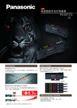
内置各种控制功能无需控制器●配备实现长距离传感的HYPR模式可紧密安装最多3台光纤。
最大为以往产品的5.7倍。
特别是使用超高精度检测的小径紧密安装最多台纤。
通信窗输入、输出电路与连接规格外形尺寸图连接图%输入、输出电路图FX-501-C2%FX-501-C2【制造】松下神视电子(苏州)有限公司江苏省苏州市新区火炬路97号客服热线 400-920-9200 传真 400-820-7185 URL /ac北 京 : 北京市朝阳区景华南街5号 远洋·光华国际C座3F电话: 010-********上 海 : 上海市浦东新区陆家嘴东路166号 中国保险大厦7楼 电话: 021-********广 州 : 广州市越秀区流花路 中国大酒店商业大厦9楼 电话: 020-********大 连 : 大连市西岗区中山路147号 森茂大厦24F电话: 0411-********沈 阳 : 沈阳市和平区中华路69-1号B座 富丽华国际商务中心18楼 电话: 024-********成 都 : 成都市顺城大街8号 中环广场2座23楼01-03室 电话: 028-********重 庆 : 重庆市渝中区邹容路68号 大都会商厦1701-12A室 电话: 023-********深 圳 : 深圳市福田中心四路1-1号 嘉里建设广场三座4楼 电话: 0755-********天 津 : 天津市和平区南京路75号 天津国际大厦1001室电话: 022-********江 苏 : 江苏省南京市鼓楼区中山北路45号 江苏怡华酒店写字楼13F 电话: 025-********杭 州 : 杭州市凯旋路445号 浙江物产国际广场4层C座 电话: 0571-********武 汉 : 武汉市解放大道686号 世界贸易大厦1706-07室 电话: 027-********郑 州 : 郑州市金水区未来大道69号 未来大厦1512室电话: 0371-********西 安 : 陕西省西安市曲江新区芙蓉南路3号中海大厦7层04-05单元 电话: 029-********青 岛 : 青岛市市南区福州南路8号 中天恒大厦90A室 电话: 0532-********厦 门 : 厦门市厦禾路189号 银行中心2311室电话: 0592-*******All Rights Reserved © 2014 COPYRIGHT Panasonic Industrial Device SUNX Suzhou Co., Ltd.松下电器机电(中国)有限公司注册地址:中国(上海)自由贸易试验区马吉路88号7、8号楼二层全部位联系地址:上海市浦东新区陆家嘴东路166号中国保险大厦6楼松下电器机电(中国)有限公司 控制机器营业本部业务咨询:(注1):无指定时的测量条件为使用环境温度=+23℃。
神视FX-501-C2放大器常用调试说明书[优质PPT]
![神视FX-501-C2放大器常用调试说明书[优质PPT]](https://img.taocdn.com/s3/m/2e045f425f0e7cd18425366f.png)
“
”代表设定值(绿色)比检测值(红色)高时有输出。
2.2、 按“+”键或“-”键选择所需要的输出设置。
2.3、 按“SET”键一下,显示并闪烁,设定完成。
2.4、 按“MODE” 键三下,返回到待机画面。
三、模式设置:
神视FX-501-C2放大器常用调试说明书
第4页
模式分类: 1、强等:
2、中等
3、弱等
1.4、 按“MODE”键两下,完成后会自动返回待机画面。
1.5、 设定值调整 :
1.5-1、 在没有放入检测物的状态下,观察并记录当前检测值(红色)。
1.5-2、 在放入检测物的状态下,观察并记录当前检测值(红色)。
1.5-3、 计算初步设定值:
① 有料检测值>无料检测值时 ,初步设定值=(有料检测值-无料检测值)/2+无
”并闪烁,这时感应器复位中,完
成后会自动返回待机画面。
”。
Hale Waihona Puke 二、输出、常开/常闭设置: 神视FX-501-C2放大器常用调试说明书
第3页
输出常开/常 闭设置
模式设 置按钮
二、输出设置(常开/常闭设置) :
2.1、 在待机画面按“MODE” 键一下,显示当前输出设置状态。
“
”代表设定值(绿色)比检测值(红色)低时有输出。
第2页
复位设置
模式设置 按钮
一、复位设置
1.1、 在待机画面按“MODE” 键三下,显示“ ”。
1.2、 按“SET”键一下,显示“
”。 1.3、 按“+”键四下,显示“
1.4、 按“SET”键一下,显示“
”。 1.5、 按“+”键二下,显示
日本神视LED线性传感器 LA-300解读

日本神视LED线性传感器LA-300小型尺寸安全的红色LED光简易光轴对齐投光器与受光器比放大器内置型(LA-510)更小。
因此可以安装在自动装配机器等的狭小空间内。
由于采用了安全的红色LED作为光源,对眼睛无害,所以无需遵从激光安全守则。
而且,由于红色LED光源的测定光点容易看见,使物体定位简单。
使用光轴调整标签(附件)。
使光轴对齐简单。
而且在放大器上的3级稳定指示灯指示入光水平,一目了然。
两个比较输出加一个模拟输出除了1~5V的模拟输出还装备了两个比较输出(HIGH,LOW)。
幅度及移位调整外部同步模拟输出除了装备有幅度调整功能外,还有使模拟电压可在±0.5V范围内进行转换的移位调整功能。
例:使用一定量遮光,将模拟电压从2.51V转换到3.00V。
外部输入可以控制比较输出的同步性和持久有效性。
(有微分同步或期间同步可供选择)日本神视LED线性传感器LA-300用途检测脱离晶片检测工作件上的毛口检测玻璃瓶两个传感器从垂直和侧面方向检测晶片的位移。
毛口将增加遮光的宽度。
即使是透明玻璃瓶也可被可靠检测。
订购指南检测头[请配套使用检测头和放大器。
]放大器[请配套使用检测头和放大器。
]·MS-LA3-2 [用于LA-305的检测头安装支架]注:在投光器和受光器上都安装时,需要2种。
日本神视LED线性传感器LA-300配件(另售)CA2系列·CA 系列自动参照功能,零调节功能,150mA主要功能:数学功能,待机功注:如果LA-A1或LA-A1P的模拟输出改变,输入范围也将超出。
此时使用CA2-T5或CA-□5(输入范围-10~+10V)。
详情请咨询。
规格检测头放大器注:这是一款符合EMC指令适用品。
此产品在免疫力方面的标准符合EN 61000-6-2,同时下列条件也符合此标准。
条件:·放大器与电源之间的连接距离应在10m以下。
·连接放大器的信号线应在30m以下。
- 1、下载文档前请自行甄别文档内容的完整性,平台不提供额外的编辑、内容补充、找答案等附加服务。
- 2、"仅部分预览"的文档,不可在线预览部分如存在完整性等问题,可反馈申请退款(可完整预览的文档不适用该条件!)。
- 3、如文档侵犯您的权益,请联系客服反馈,我们会尽快为您处理(人工客服工作时间:9:00-18:30)。
12 22 25 40 "6.4
18 20 注1) ( 62
35
6 光轴中心 50
6.4
10
(注1): 透过型传感器投光器上没有装备。 (注2): NX5-M10R□投光器上没有装备。在NX5-M30□投光 器上是电源显示灯 (红色) 。 (注3): NX5-M10R□投光器,NX5-M30□投光器和受光器或 NX5-RM7□上没有装备。
安装有狭缝透光罩(OS-NX5-3 6),可测试小到3 但安装了狭缝透光罩后检测距离将减小。 安装
1将狭缝透光罩的C部分装在主体盖的凹槽A中。 2然后对着主体按下狭缝透光罩使狭缝透光罩挂钩D部 分嵌入主体盖的凹槽B中。
6mm的物体。
凹槽B D
传感器
传感器安装支架 (另售)
输出和显示灯间的关系 L ON · (入光时ON)
安装距离 投光器 受光器
(单位:mm) 12 尺寸
NX5系列
灵敏度调节器 (注2)
MS-NX5-1的安装 (另售安装支架)
(43) 40 21 5.2
“P” 的为透过型传感器投光器,D” “ 的为透过型传感器受光器。 (注1): 在铭牌上型号后缀 如 透 过 型 传 感 器 投 光 器 为 : NX5-M10RP, 透 过 型 传 感 器 受 光 器 为 : NX5(注2): M10RAD 带偏极滤光镜的回归反射型传感器透过透明胶片检测光泽或光滑物体时,由于 “9带偏极滤光镜的回归反射型传感器” 。 (注3): 光线偏化可能会不稳定。请参考 回归反射型传感器的检测距离和检测物体是对反射镜RF-230的值。检测距离是 反射镜可放置距离。传感器可检测0.1m以内的物体。
通 过 安 装 防 干 扰 滤 镜 ( PF-NX5-□) , 使 两 台 NX5-M10R□可靠近安装。 滤镜安装方法同狭缝透光罩。 有两种型号的防干扰滤镜。两台透过型传感器 应该与不同类型的滤镜安装在一起。
(注1):NX5-M30□型不可用滤镜。
与PF-NX5-H 安装
保 护 构 造 IP66 (IEC) 20~ 55℃ (不可结露或凝霜)注6) ( ,保存时: 30~ 70℃ 使用环境温度 35~85%RH,保存时:35~85%RH 使用环境湿度 光 源 红色LED 红外LED 红色LED 红外LED 材 质 外壳,透镜和罩:聚碳酸酯,前罩:丙稀 (仅限于回归反射型传感器) (透过型传感器投光器:2芯) 橡皮电缆,长2m 0.3mm25芯 电 缆 投光器:约100g 投光器:约125g 约140g 重 量 受光器:约140g 受光器:约140g 附 灵敏度调整 件 螺丝刀:1个 灵敏度调整 RF-230(反射镜) 个 :1 灵敏度调整螺丝刀:1个 (NX5-PRVM5□) 螺丝刀:1个
非常感谢您购买SUNX产品。请仔细、完整地阅读此使用说明书以便正 确、合理地使用此产品。请把此使用说明书放在随手可得之处以便快速 查找。
光轴调整 透过型传感器
1将投光器和受光器沿直线相对放置,上下左右移动投 光器,通过操作显示灯(红色)来判断受光范围,然后把 投光器设定在该范围中心位置。 2上下左右角度移动投光器,与上述同样进行调整。 3同样调整受光器的角度。 4检查稳定显示灯(绿色)是否亮起。
使用说明书
光电传感器(接近开关) 多电压
NX5 系列
执行标准号:GB/T 14048.10 MC-NX5 No.0004-59V
警告
请勿将本产品作为人体保护用的检测装置。 如以人体保护为目的,请使用OSHA、ANSI及IEC等各国适 用于人体保护用的产品。
投光器
1 主要规格
类 型 型号 入光时ON (注1) 遮光时ON 项目 检 测 距 离 检 测 物 体 应 差 透过型 长检测距离 NX5-M10RA NX5-M30A NX5-M10RB NX5-M30B 10m 30m "20mm 以上不透明 物体 (注5) 回归反射型 扩散反射型 带偏极滤光镜 (注2) 长检测距离 NX5-PRVM5A NX5-RM7A NX5-D700A NX5-PRVM5B NX5-RM7B NX5-D700B 0.1~5m (注3) 0.1~7m (注3) 700mm (注4)
在中国印刷
URL : sunx.jp
检测物体
2007年5月
"50mm以上不透明、"50mm以上不透 不透明、 半透明或 半透明或光泽物体 明或半透明物体 透明物体 (注3) (注3)
3 安装
紧固扭矩应在0.8N m以下。
M4螺母 带垫圈M4 长25mm) ( 螺丝
回归反射型传感器
1将传感器和反射镜沿直线相对放置,上下左右移动反 射镜,通过操作显示灯(红色)来判断受光范围,然后 把反射镜设定在该范围中心位置。 2上下左右角度移动反射镜,与上述同样进行调整。 3同样调整传感器的角度。 4检查稳定显示灯(绿色)是否亮起。
MIN. MAX.
10 90 104 56 6.4 t2 6 5 12 22 光轴中心
18 42 6 6.4
10°
(注1): 使用调整螺丝刀缓慢旋转灵敏度调节器。用力过大会损坏调节器。
受光状态
透 过 型 回 归 反 射 型 扩 散 反 射 型 传感器 反射镜 传感器 检测物体 反射镜 投光器 受光器 投光器
MS-NX5-2的安装 (另售安装支架)
MS-NX5-3的安装 (另售安装支架)
A
B
在遮光状态下,继续顺时针旋转调节器,一旦传感器进入受光状态,逆时针方 向旋转至B点,传感器再次进入遮光状态。 (如果灵敏度调节器完全顺时针旋转,传感器仍没进入受光状态,这一点是B点。 )
8 长检测距离的回归反射型传感器( NX5-RM7 □)
(注1):透过型传感器投光器电源仅有两条线路。
与PF-NX5-V 安装
5 调节
调节部
稳定显示灯 (绿色) (注1) 操作显示灯 灵敏度调节器 (红色) (注3) (注2)
7 透过型防干扰对策
如果在使用NX5-M10R□时发生相互干扰,可用防干扰滤镜(PF-NX5-□) 将两台传感器靠近安装。 [详情参见 11 防干扰滤镜 (另售) ]。 如果无防干扰滤镜的NX5-M10R□或NX5-M30□安装在一起时发生相互 干扰,我们建议投光器和受光器选择其一按照下图所示的距离放置。 此外,若保持了指定距离还发生干扰,应放置光栅等。 例:
检测物体
(另售) 透过型传感器专用) ( 10 狭缝透光罩
反射镜
电 源 电 压 消 耗 电 流
输
出
反 应 时 间 操 作 显 示 灯 稳 定 显 示 灯 电 源 显 示 灯 灵敏度调节器 自动防干扰功能
15%以 下 操 作距离 24~240V AC +10 %或12~240V DC +10 % 脉动P-P 10%以下 -15 -15 投光器:1VA以下 投光器:1.5VA以下 2VA以下 受光器:2VA以下 受光器:2VA以下 继电器接点 1c 转换容量: 250V 1A AC (抗负荷) 30V 2A DC (抗负荷) 电子寿命: 10万次以上操作 (额定交流负荷时) 50万次以上操作 (额定直流负荷时) 机械寿命: 1亿次以上操作 10ms以下 红色LED (当输出ON时灯亮) 绿色LED (在稳定受光或稳定遮光状态下灯亮) 红色LED (当电源ON时灯亮) 连续可变调节器 连续可变调节器 连续可变调节器 使用另售防干 装备 (两台传感器可靠近安装) 扰滤镜
光轴中心
72
2个"4.5 安装孔 (用于安装) 2个M4 螺母孔 (双侧)
51 4 25 "5.8电缆2m t2
传感器 反射镜 反射镜
灵敏度调节 (不包括NX5-M30□,NX5-RM7□)
步骤 灵敏度调节器 说 明
保持足够距离 NX5-M10R□ :约1m以上 (10m设定距离) NX5-M30□ :约2.5m以上 (30m设定距离)
2 注意事项
本产品是以工业环境使用为目的所开发、制造的产品。 请确认在电源关闭状态下进行接线。 注意错误接线可能损坏传感器。 请勿与高压线或电源线一起或在同一电线管内运行线路。这可能会由于感 应引起失灵。 请确认电源电压在额定范围内变化。 如果电源由一商用开关调节器提供,请确保电源机架接地端子(F.G.)接地。 电源接通后的短时间50ms内,请勿使用。 如果在该产品附近使用产生噪音的设备,如开关调节器或转换发动机等, 请将设备机架接地端子(F.G.)接地。 0.3mm2以上电缆可延长至总长不超过100m。 当连接一个如DC继电器的感应负荷时,连接一个如右图所示的电涌吸收器。 请勿将传感器直接暴露于快速启动灯或 DC继电器 高频照明设备的荧光下,这样会影响检 确保连接了 电涌吸收二 测性能。 传感器 极管 输 COM. 本传感器仅适用于室内使用。 出 + 避免灰尘、污垢和水蒸气。 继 - 请勿将传感器与水、油、油脂或有机溶液, NO 电 器 NC 如稀释剂等直接接触。 为了与CE使用条件一致,需遵循以下几项: ·输出额外电压应该与传感器电源电压相同。 ·确保为电源电压的输入和输出增加短路保护 (保险丝或断路器) 。
A
受光器
投光器
(注1):回归反射型和扩散反射型传感器则为 20.5。 (注2):在NX5-M10R□投光器,NX5-M30□ 投光器和受光器或NX5-RM7□上没 有装备。
(注1):如图所示安装NX5-M10R□受 光器。
在受光状态下,缓慢顺时针旋转调节器到传感器进入受光状态的A点。
MIN. MAX.
64
遮光状态
受光器
传感器 L 距离L应尽可能长
(注1):如图所示安装NX5-M10R□受光器。 (注1):如图所示安装NX5-M10R□受光器。
检测物体 传感器 传感器
