proe管道教材 中文版piping
ProE管路标准教程
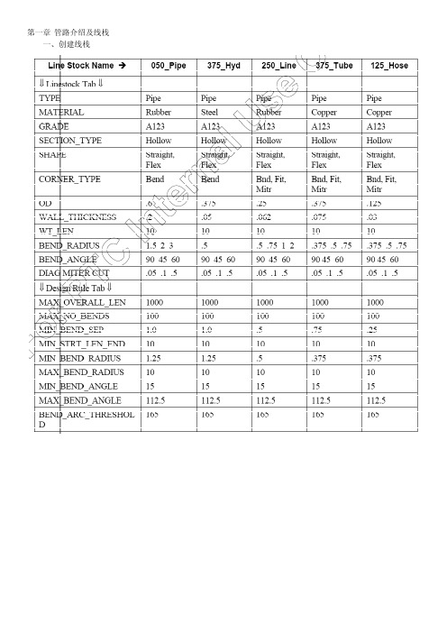
一、创建线栈一、 Routing Pipelines a) First pipeline 1. Open the BASIC_ROUTING.ASM 2. Enter the Piping module. Click Applications > Piping 3. Read in the 1_Hose line stock file. 4. Create a pipeline feature. Click Pipe Line > Create/Route, enter[Line_1], and select [1_HOSE] as the active line stock 5. Route pipeline from Port3_V on the vessel to Port2_MT 。
b) Second pipeline 1. Create pipeline line_2 2. Set start point , ToPnt/Port > Point/s 3. Follow > Axis > Done, and pick the firstaxis shown Figure 12, and click Done Follow. 4. Again, click Follow > Axis > Done, and pick the second axis inFigure 12. Click Change > Ends > Done > Accept, Drag, andDone, to accept the right side of the axis. Using the cursor, drag the endpoint of the axis to the right andclick. Click Ext Length, and enter [2.5], then click Done andDone Follow. 5. Connect some of the pipe segments. Click Connect > Pipe End,and pick the first pipe end shown below. Click Pipe End again,pick the second pipe end, and click Done and Done Connect. 6. Next, view alternatives to connect the two axes segments. Click Connect > Pipe End, and pick the first pipe end, then click Pipe End again Pick the second pipe end shown below and click Done,and Done Connect. 7. Now try the same routing with a different option. Click DeleteLast, then Set Start, Pipe End, and pick the first pipe end shownabove. Click To Pnt/Port, Pipe End, and pick the second pipe end.Notice the difference in the pipeline. 8. Complete the routing of LINE_2 ,CREAT SOLIDc)Create LINE_3 and LINE_4 using different Point options.1. Create a new pipeline. Click Pipe Line > Create/Route, enter[LINE_3], and select [1_HOSE]as the active line stock.2. Set Start ToPnt/Port ToPnt/Port3.DOWN4.To assist in Routing, it is possible to use an array of datum points.Route LINE_4 using thistechnique. Create a new pipeline. ClickPipe Line > Create/Route, enter [Line_4], and select [1_HOSE]as the active line stock.5.Click Set Start > Entry Port, and pick Port2_MT on the multitank.Click ToPnt/Port > Point/s,and pick the point just beyondPort2_MT.6.Set Start ToPnt/Port ToPnt/Portd)Route LINE_5 using flexible shape pipeline.1.Create a new pipeline. Named line_52.Create some disjointed pipeline segments following the axesshown below. Click Follow >Axis > Done, and the first axisshown below, and Done Follow. Repeat for the second axis.3.Change the current piping environment. Click Pipe Environment> Line Shape > Flexible >Done > Done Return. To route the flexible line, click Set Start, and pick one of the pipeends,followed by ToPnt/Port, and the other pipe end.4.Make solide)The final pipeline will use sketches for routing.1.Create a new pipeline. Named [line_6]2.Before routing the next pipeline, change the Pipe Environmentdefaults. Click PipeEnvironment > Line Shape > Straight >Done > Corner Values > [3.00] > Done Return.3.Create some disjointed pipeline segments following the axesshown. Click Follow > Axis >Done, and pick the first axis shownbelow. Click Change > Ends > Done > and accept theouter pointof the axis, then click Drag, and ing the cursor, drag the endpoint of the axis outward and click.Click Ext Length, and enter [3.0], then click Done and DoneFollow.Repeat for the second axis, using [2.0] as the extensionvalue.4.Next, the first portion of the pipeline will follow a sketch. ClickFollow > Sketch > Done.For the sketching plane, click MakeDatum > Through, and pick the first axis in Figure 26.ClickParallel, and pick the top surface of the Base.5.Down the sketch as follow6.After completing the sketch, click Done > Done Follow, and theCONNECT menu shouldappear. Notice how the new defaultradius from the line stock set in the Pipe Environment is applied to the corners of the sketch. Click Pipe End, and pick the end of the follow axis segment, then click Done, and Done Connect. When the free end of the pipeline highlights, click Quit Connect and return to the ROUTE PIPE menu.7.Before sketching the next segment,change the PipeEnvironment defaultsagain. Click Pipe Environment >CornerType > Miter Cut > Done >Square > Done, and Done Return.8.Sketch the second portion ofthe pipeline. Click Follow >Sketch >Done. For the sketching plane,click Make Datum > Through, andpickthe axis as shown in Figure 29. ClickNormal, and When the sketch is completed, click Done > Done Follow, and the9.CONNECT menu should appear. Click Pipe End and pick the end of the follow axis segment,thenclick Done, and Done Connect. When the free end of the pipelinehighlights, click Quit Connect.Sel ByMenu > Sel By Menu > Basic_Routing.asm > Datum > Name >A‐Right_1, and Done.10.The final segment will be completed using flexible line. Changethe current pipingenvironment. Click Pipe Environment > LineShape > Flexible > Set Length > Done > Done Return.11.To route the flexible line, click Set Start, and pick one of the pipeends, followed byToPnt/Port, and the other pipe end. Enter [5.5]as the fixed length of pipeline, and click Done Return.12.Make solid.第三章 进阶布线技术一、Using Additional Routing Techniquesa)Route the first pipeline1.Open the ADDL_ROUTING.ASM2.Read in the 1_Hose line stock file.3.Create a pipeline feature nemed [line_1]4.Click Set Start,and select PORT1_V,and Extend [3.0]5.Click Extend > Direction, and select the upper horizontal edge ofthe Base. Click EnterLength, note the direction of the arrow, andenter [‐4.0].e Extend Direction a little differently, the same direction ,extend [5]7.Route the pipeline towards the Base. Click Extend > UpTo, andpick the Base surface asshown in Figure 12. Click Enter Length,and enter [7.0]8.Begin routing from the end of the pipeline. Click Set Start, andselect the PORT1_P on thePump as shown in Figure 12. Extendthe pipeline in the Z‐axis direction of the port. ClickExtend, enterthe length, and enter[3.0]9.Click Extend > UpTo, pick the surface on the pump in Figure 12,click Enter Offset, andenter [-2.0]. Complete the routing byclicking Connect, and pick each free pipe end, thenclick Done >Done Connect. Refer to Figure 13. DO NOT make a solid pipe atthis timeb)Route the second pipeline1.Create a pipeline feature and nemed [line_2]2.Click Set Start, and select PORT2_V, Extend and Enter Length, and enter [3.0].3.UpTo, pick the first surface of the bracket, than up and Offset [3.0] of the other surface,change the corner value to [0.75]4.Extend > UpTo base surface and offset [2.0]5.Begin routing fromthe end of thepipeline.6.Extend [3]7.Y‐Axis [6]8.x‐Axis [6]9.Changing LineShape to Flexible10.To Pnt/Port,finishc)Begin the third Pipeline. Use a combination of Follow Curve and Extend1.Create a pipeline feature nemed [line_3]2.Set stard point,Extend andEnter Length, and enter [5.0].3.Click Follow > Axis > Done,and select A_1 on the Block,and click Done Follow.4.Click Follow > Curve, Done,pick the first curve shown inFigure 19, then click SelectAll > Done, Done Follow.Repeate Connect to create FOURconnections between the pipesegments6.Click Extend > Direction,pickthe underlying datum curve inFigure 20 and extend to theleft[4.0]. Click Done andDone-Return.d)Begin Routing LINE_4. Use Follow Pipeline for the major routing.1.Create a pipeline feature nemed [line_4]2.Begin routing LINE_4 from the unused port on the first Pump.Click Set Start, and pickPORT2_P on the pump as shown inFigure 21. Route the pipeline using various extendcommands, andclick ToPnt/Port to arrive at APNT0. (此处是随意布线)3.Route the next segment using a follow pipeline. Click Follow >Pipeline > Done, pick Line_3,click Specify, and Done to specify the start and end segments as shown in Figure 22.4. Start Point, Done, pick APNT0, and click Done Follow.5.connect the segmenting Routing commands of your choice , complete the routing for the two lines asfollow.e)Lines 5 and 6 will require some branching. Create the Pipelinesand Branch into Line 2, createdearlier.1.Create a pipeline feature nemed [line_5]2.Begin routing LINE_5 from the Multi Tank as shown. Click Follow > Axis > Done, pick axisA_4, and then click ChangeEnds > Done. Accept the outer end. Use Drag and Ext Length to extend past the axis [6.0]. Click Done > Done Follow. Click Set Start > Pipe End, and pickthe end of the pipeline.3.Click Branch > Perpendicular(垂直,正交), and pickLINE_2. Click Done-Return whenfinished. Refer to Figure 24.4.Create another pipeline featurenamed [line_6]5.Begin routing LINE_6 fromA_8 on the same Multi Tank,and use the same Follow andChange End procedure as withA_4.6. In order to create this branch,you will create a datum pointon LINE_2. Click Branch > ToPoint > Create Pnt, pick alocation as shown on LINE_2,click Length Ratio, and enter[0.75]. Referto Figure 25.二、Using the EZRouter and Square1.Change the working directory to EZ_Route_Rect and open theEZ_ROUTE_RECT.ASM file.2.Read in the [Circ_050] and [Rect_1_2] line stock fileb)Route a pipeline that will represent a duct(电缆槽) using square pipe.1.Click PipeLine > Create> ’pl2’ >Rect_1_2.2.Click Set Start. Pick the Port2_V Csys.3. Click EZRouter and use withthe saved views. Route thepipe similar to Figure 42.4.Make the pipeline solid andtype [DUCT_1].5.6.7.第四章 Modifying Pipelinesa)Some new routing point locations are needed in LINE_2. Useinsert point to accomplish this.1.Open the Modify_Basic_Routing.asm2.Before modifying the pipeline, change the display of LINE_2 to centerline.3.Insert a point for a routing location. Click Route, pick LINE_2,and click Insert Point. Pickthe pipe segment shown to insert the point on. Click Create > Static > Done,4. Use [3.5] [3.5] [0.75] to creat the point.5.Insert another point into the pipeline , Create > Dynamic > Done.b)Use the SEL BY Menu technique to select an empty pipeline.1.Create a temporary pipeline. Click Pipe Line > Create, enter [temp], 1_HOSEc)Make several modifications to LINE_61.Click Route, pick the pipeline shown in Figure 12, click Mod Dim,and pick the sketchedsegments. Modify the [0.75] dimension to[-6.0] and click Done Sel. Pro/E automaticallyattempts toregenerate the Pipeline, and it fails because this flexible line wasconstructedwith the Set Length option, and this modificationexceeds the set length.(修改草绘中0.75到-6)2.Make solid and regenerate3.From the PIPE MODIFY dialog box, select CORNER, pick theupper left mitered corner asshown in Figure 14, and change theType to Bend with a radius of [3.0]. Use Select Cornerto pickthe upper right corner, and change its type to Fitting. Click Apply> Close, andRegenerate Automatic.(用“管道修改”修改两个拐角,左边修改为半径为3的折弯,右边修改为管接头拐角,自动再生)4.The solid pipe fails because it has split into two pieces. Delete the solid and recreate. ClickQuick Fix > Delete > Confirm, and Yes to exit Resolve mode. Click Make Solid and edit the new pipeline names to be [MOD_1] and [MOD_2]. Notice the opening between the twosolid pipe segments allows for a fitting to be placed. Referto Figure 15.(再生失败后删除实体,重新命名为两段)d)The section of pipe between the arches requires a diagonalmiter.1.Click Mod Pipe, pick thepipeline, clickDone Sel, change Bend to Diag Miter Cut,and entera value of [5.0] [2] . Click Apply,note the changes and close.2.Click Regenerate > Automatic toupdate the solid pipe.e)Modify the line stock on some pipelines.1. Click set >Line Stock > Read,and select 050_PIPE2. Mod Pipe > Line Stock, pickLINE_3, and click DoneSelect.Select 250_LINE and clickApply. Click SelectSegment again, selectLINE_FLEX, click Done Select,change to 050_PIPE,click Apply, Close, and Regenerate Automaticf)Modify some built-in angular dimensions in the multi-tank tochange the pipelines1.Click Mod Dim and pick the four nozzles on the multi‐tanks as shown in Figure 19.Modify the four 60 degrees dimensions to[90].2.Regenerate Automaticg)After modifying nozzle angles, one flexible line is stretched too tight, and the other is toocramped. Make necessary modifications to the flexible pipelines.1.Click Mod Pipe, and Flex Shape, select the LINE_FLEX, and click Fixed Length. NoticePro/E provides the current value of theflexible line. Enter [20.0], click Apply, and notehow the linebows out. Click Select Segment, pick the “S” shape in LINE_6,and change thelength to [10.0]. Click Apply, Close, and Regenerate.(前一步骤修改成了12,此处改到10)二、Using Replace Modea)The pipeline goes straight through the tank. Correct thisproblem by sketching the pipeline inthis area.1.Open REPLACE_MODE_ROUTING_E2.Click Route,Replace > Enter Replace第五章 Fittings一、Inserting fittings in a Piping Systema)Prepare some corners for fittings1.Open the FITTINGS_MOD_ROUTING.ASM2.Fittings should always be placed before solid pipes are made. Pick each pipe above inFigure 26, and use the right mouse button to delete them.(接头一般在管道实体创建之前放置,删除图示管道实体)3.Click Route, pick the pipeline as shown above in Figure 27. Click Redefine, pick thesegment again, and click Change > Sketch >Done > Sketch. Modify the sketch as in Figure28. Click Doneand Done Follow when finished.(修改草绘为接头准备)4.Modify the corners as shown in Figure 29 to fitting corners. Click Mod Pipe > Corner, pickthe three corners, and click Done Sel.Change the type to Fitting > Apply. Click Close.5.Insert three corner fittings. Click Fitting > Insert > Corner >1EL90THRD, pick the corner asshown in Figure 30, and click Done. Repeat for the other corners shown.6.Insert another corner fitting. Click Fitting > Insert > Corner >1EL45 and pick the cornershown below. Click Done, and DoneReturn.7.One of the fittings should be a corner elbow. Click Fitting >Replace, pick the fitting asshown in Figure 32, and click Manual> Done > 1EL90 > Open, then pick the pipeline corner.Click Done, and Done- Returnb)Place some additional fittings from the Multi_Fitting familycreated in the last exercise1.Click Fitting > Insert > Straight Break > Multi_Fitting > Open >The Generic > Open. ClickCreate Point. Pick the location as shown in Figure 33. Pick Length Ratio and enter [0.5].Pick the datum point on the fittingin the subwindow and click Done2.Click Fitting > Insert > Straight Continuous > Multi_Fitting >Open > Multi_BR1 > Open.Create a point ½ way along thepipeline as shown in Figure 34. Click Create Point. Pick the location shown in Figure 34. Pick Length Ratio and enter [0.5].Pick the datum point on the fitting in the subwindow, and click Done.3.The orientation of the fitting above needs to be changed. Click Redefine, select the fitting,and click Orientation. Click Flip, and Done.4.Click Redefine, select the fitting, and click Orientation a second time. Click Twist > EnterValue, enter [45] > Done > Done >Done, and Done-Return. Your assembly should resembleFigure38.c)Next, create some extract models for documentation purposes.1.Click Extract Model > Extract. Enter [EXT_LINE_1], and pick allcomponents in LINE_1. Click Done Sel,Done. Repeat theprocess, creating two more extract models for LINE_2 andLINE_6 as shown in Figure 39.Notice these models ARE addedto the MODEL TREE for this assembly as components, however,they maybe deleted from the assembly so as to not interfere with aBOM, and can still be opened independently.2.Repeat ,repeat ……第六章 Piping Information and Drawings一、Extracting Bend Information1.Open the INFO_DRW_ROUTING assembly.2.Select ANALYSIS > MODEL ANALYSIS, and GLOBAL INTERFERENCE from the TYPEdrop down list. Notice there are at least five pairs of interfering components. Use theup/down arrows to investigate each pair(查看全局干涉)3.Investigate the information options in the PIPING INFO dialog box. Select INFO from thePIPING menu (or INFO, PIPING from the pull-down menu). The PIPING INFO dialog boxappears, with the default Info Type as General, and the drop down option set to Pipe Line(查看管道信息对话框,使用“常规”和“管线”“管段”)4.Pick the pipeline shown in Figure 6 and read the information provided. Change the dropdown option to Segment, and then pick the segment shown in Figure 6. Notice theincreased information.5.Generate a BOM. Select BOM from the drop down list. Scroll down the window to viewthe BOM. For easier viewing, click Info. Close the large info window when finished.6.Select Length from the INFO TYPE drop down list. Notice there are several options: PipeLine, Segment, Stock, as well as Pre/Cut or Centerline. Select PIPE LINE > CENTERLINE,and pick the pipeline shown (LINE_6). (查看管段的长度,查看管线6的长度)7.Change the Length Type to Pre/Cut and observe that the length is identical in this case(58.32).(使用预切割模式和中心线模式查看管线6长度)8.Mod these corners as follow9.Repeat the 7th ,(注意到两种模式下的管线长度不一样)10.Change the definition drop down from Pipe Line to Line Stock. Notice the system lists allline stocks used in this assembly. Select 1_HOSE, and Pro/E calculates the total length ofraw 1_HOSE linestock required for this assembly.(查看线栈1_HOSE的管段长度)b)Take advantage of parameters in the Line Stock, andperform a pipe check operation.1.Change the Info Type to Check Pipe, and pick the same pipeline segment as in Figure 15.Notice the various violations. Use the up/down arrows to highlight the geometry.2.click Linestock > Edit >1_HOSE > Check Pipe, and change the MIN_BEND_SEPARATIONto [2.00], the MIN_STRAIGHT_LENGTH_END to [1.00]. Click OK > Done-Return,and Regenerate > Automatic.(将最小折弯间隙改为2,最小直段长度为1)3.Repeat the 1sd (重复第一步,发现违规减少)c)Generate Bend Machine and Bend Location Data for a pipeline.1.Set the Display of the pipeline as shown to centerline2.Click Info > Piping > Bend Location, and pick the segment and coordinate system, clickDesignate for Report Setup, and Info. Save the analysis. Click Saved Analyses, enter[BEND_LOC], and [Save]. (注意,此处需要保存报告)3.Change the Info Type to Bend Machine and pick the segment as in Figure 19. (Be sure toflip the direction of the arrow, if necessary), click Designate for Report Setup and Info.Save the analysis.Click Saved Analyses, enter [BEND_MACH], and [Save]. Close the dialog box when finished. (保存折弯机信息)4.Set the Display of the pipeline back to Solid. (不要关闭窗口)d)Create a drawing which extracts bend machine and location data from LINE_6, and also usesa custom BOM with repeat regionparameters.1.Click File > New > Drawing, and enter [Pipe_Info], OK,INFO_DRW_ROUTING.ASM asthe default model, no template, size C and click OK.2.Create a view of the entire assembly. Click Views > Add View >General > Full View > NoXsec > Unexploded > Scale > Done,pick a point in the upper left corner of the screen, andenter [0.20].Turn off the display of all datum features, and change the displayto No Hidden.3.Two tables have been saved in your directory that contain onlysome plain text. Place themon the drawing. Click Table >Save/Retrieve > Retrieve > Bend_Loc._Table.tbl > OK, andplace the table on the drawing. Repeat for the Bend_Machine_Table.tbl. Position the tablesas shown in Figure 20.(从文件插入两个表格)4.Create a repeat region in the first table. Click Table > Repeat Region > Add > Simple5.Enter the following parameters in the first table6.Enter the following parameters in the second table7.For each table, click Repeat Region > Attributes, select the region, and click No Duplicatesand Recursive > Done, then Update Tables.(设置无多重记录,递归的)e)Create the Bill Of Materials.1.Click Table > Save/Retrieve> Retrieve > PIPING_BOM_TABLE.tbl > Open,(插入BOM)2.For each region, click Repeat Region > Attributes, select the region, and click No Duplicatesand Recursive > Done and Update Tables. Click Filters > By Item, select the three extract models and the assembly, and click Done Sel > Done.(定义无重复,递归,过滤)3.Click Attributes > Start Index, select the lower region, and then the upper region. Click SortRegions, select the upper region,click Add > Forward, select the name column, then click Done Sel> Done. Refer to Figure 25.(定义起始编号)4.Show the BOM balloons. Click BOM Balloon > Set Region,select the upper region, andclick Show > All. Use Detail Create Balloon for the lower region. Adjust the balloons using Detail Move or Mod Attach.(定义球标)。
PDSOFT使用手册《第四部分 3DPiping平立面图》

——3DPiping平立面图北京中科辅龙计算机技术有限公司2004年1月目录第1章新建平剖图 (155)1.进入平立面系统 (155)2.新建平剖图 (155)3.给定平剖图文件名 (158)4.剖切范围定义 (159)5.生成图纸中的提示 (160)6.返回模型 (161)第2章编辑标注平剖图 (163)1.打开平剖图 (163)2.标注参数设置 (163)3.标注的样式设置 (165)4.插入图框 (167)5.图形编辑 (168)6.尺寸标注 (171)7.文字标注 (176)8.特殊符号 (180)9.辅助工具 (186)第3章从模型更新平剖图 (189)1.编辑返回保留标注 (189)2.重建平立面图 (189)3.其他 (191)PDSOFT 使用手册《3DPiping 平立面图》 第1章 新建平剖图155第1章 新建平剖图管道模型经过模型检查后,确认管道模型无论在模型软件结构方面,还是在模型数据库、图形库正确性以及管道安装碰撞检查方面都是正确的时,用户就可以进入平立面图环境,自动生成平立面图。
1.进入平立面系统在配管模型环境,鼠标拾取生成平面图、立面图选项,进入平剖图环境,菜单转换成平剖环境的菜单。
图 1-12.新建平剖图鼠标拾取新建平剖图选项,开始新建平剖图过程。
第1章新建平剖图PDSOFT使用手册《3DPiping 平立面图》156图1-2进入平剖环境设置对话框:图1-3鼠标点取平剖环境设置对话框中的各项可以进行相应设置,包括:1) 设置剖切视图方向。
图1-4鼠标拾取列表中的平剖图视向,这几个视图方向在世界坐标系中的方向分别是:(1) 平面图:从+Z往-Z方向看。
(2) 前剖图:从-Y往+Y方向看。
(3) 后剖图:从+Y往-Y方向看。
(4) 左剖图:从-X往+X方向看。
(5) 右剖图:从+X往-X方向看。
PDSOFT 使用手册《3DPiping 平立面图》 第1章 新建平剖图1572) 设置图纸类型。
piping使用手册
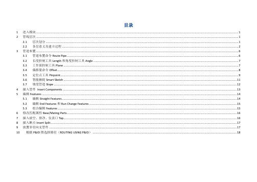
目录1 进入模块 (1)2 管线层次 (1)2.1 层次划分 (1)2.2 各层意义及建立过程 (2)3 管道布置 (6)3.1 管道布置命令Route Pipe (6)3.2 长度控制工具Length和角度控制工具Angle (7)3.3 工作面控制工具Plane (7)3.4 偏移量命令Offset (8)3.5 定位点工具Pinpoint (9)3.6 智能捕捉Smart Sketch (11)3.7 坡度管道Slope (12)4 插入管件Insert Components (13)5 编辑Features (14)5.1 编辑Straight Features (14)5.2 编辑End Features和Run Change Features (15)5.3 组合编辑Features (15)6 修改匹配属性Base/Mating Parts (16)7 插入放空、排净、仪表口Tap (16)8 插入断点Insert Split (17)9 放置非径向支管件 (17)10 根据P&ID图选择路径(ROUTING USING P&ID) (18)1进入模块菜单栏Task→Piping,左侧出现管道工具条如图1-2所示。
图1-1 进入Piping模块图1-2 管道工具条2管线层次2.1层次划分如图2-1所示,管道系统层次划分如下,必须建立Pipeline系统才能开始绘制管道。
图2-1 管道系统层次划分图2-2管道层次划分示例2.2各层意义及建立过程1)Pipeline 管线Pipe run的上一级管理层,必须建立Pipeline系统方可绘制管道。
建立环境:界面右侧Workspace Explorer(WSE)→System标签建立过程:在上一级系统图标上右键单击→New System→New Pipeline→Property Pages Dialog→填入Name(其它属性选填)→OK图2-3建立Pipeline系统图2-4 Pipeline属性对话框2)Pipe run 管段具有同样属性的一个或多个Feature的集合,多条Pipe run组成Pipeline。
Piping component中英文对照
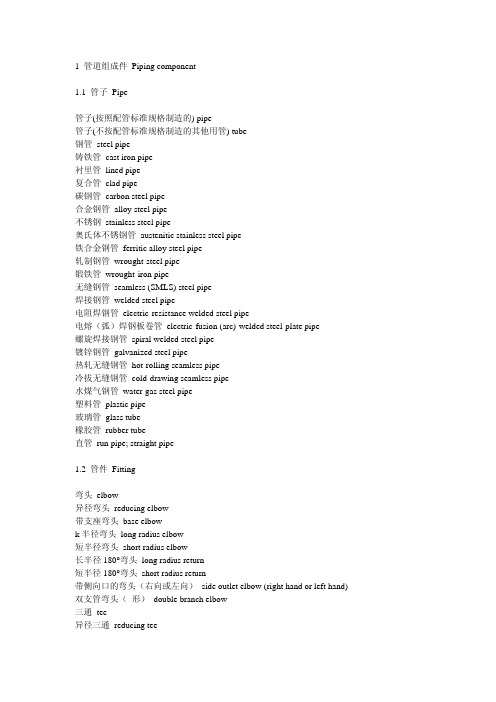
1 管道组成件 Piping component1.1 管子 Pipe管子(按照配管标准规格制造的) pipe管子(不按配管标准规格制造的其他用管) tube钢管 steel pipe铸铁管cast iron pipe衬里管 lined pipe复合管 clad pipe碳钢管 carbon steel pipe合金钢管alloy steel pipe不锈钢stainless steel pipe奥氏体不锈钢管austenitic stainless steel pipe铁合金钢管ferritic alloy steel pipe轧制钢管 wrought-steel pipe锻铁管 wrought-iron pipe无缝钢管seamless (SMLS) steel pipe焊接钢管welded steel pipe电阻焊钢管electric-resistance welded steel pipe电熔(弧)焊钢板卷管 electric-fusion (arc)-welded steel-plate pipe螺旋焊接钢管spiral welded steel pipe镀锌钢管 galvanized steel pipe热轧无缝钢管hot-rolling seamless pipe冷拔无缝钢管cold-drawing seamless pipe水煤气钢管water-gas steel pipe塑料管 plastic pipe玻璃管 glass tube橡胶管 rubber tube直管run pipe; straight pipe1.2 管件 Fitting弯头 elbow异径弯头 reducing elbow带支座弯头 base elbowk半径弯头 long radius elbow短半径弯头short radius elbow长半径180°弯头long radius return短半径180°弯头short radius return带侧向口的弯头(右向或左向)side outlet elbow (right hand or left hand) 双支管弯头(形) double branch elbow三通 tee异径三通 reducing tee等径三通 straight tee带侧向口的三通(右向或左向)side outlet tee (right hand or 1eft hand)异径三通(分支口为异径)reducing tee (reducing on outlet)异径三通(一个直通口为异径)reducing tee (reducing on one run)带支座三通 base tee异径三通(一个直通口及分支口为异径)reducing tee (reducing on one run and outlet)异径三通(两个直通口为异径,双头式)reducing tee (reducing on both runs, bull head) 45°斜三通 45° lateral45°斜三通(支管为异径)45° lateral (reducing on branch)45°斜三通(一个直通口为异径) 45° lateral (reducing on one run)45°斜三通(一个直通口及支管为异径) 45° lateral (reducing on one run and branch)Y型三通(俗称裤衩) true “Y”四通 cross等径四通 straight cross异径四通 reducing cross异径四通(一个分支口为异径)reducing cross (reducing on one outlet)异径四通(一个直通口及分支口为异径)reducing cross (reducing on one run and outlet)异径四通(两个分支口为异径)reducing cross (reducing on both outlet)异径四通(一个直通口及两个分支口为异径)reducing cross (reducing on one run and both outlet)异径管 reducer同心异径管 concentric reducer偏心异径管 eccentric reducer锻制异径管 reducing swage螺纹支管台 threadolet焊接支管台 weldolet承插支管台 sockolet弯头支管台 elbolet斜接支管台 latrolet镶入式支管嘴 sweepolet短管支管台 nipolet支管台,插入式支管台 boss管接头coupling, full coupling半管接头 half coupling异径管接头 reducing coupling活接头 union内外螺纹缩接(俗称补芯) bushing管帽 cap (C)堵头 plug短节 nipple异径短节reducing nipple; swage nipple1.3 弯管 Bend预制弯管fabricated pipe bend跨越弯管(^ 形) cross-over bend偏置弯管(~ 形) offset bend90°弯管 quarter bend环形弯管 cirele bend单侧偏置90°弯管(? 形)single offset quarter bendS形弯管 “S” bend单侧偏置U形膨胀弯管(| ?形)single offset “U” bendU形弯管 “U” bend双偏置U膨胀弯管double offset expansion “U” bend斜接弯管 mitre bend三节斜接弯管3-piece mitre bend折皱弯管 corrugated bend圆度 roundness1.4 法兰 Flange (FLG)整体管法兰 integral pipe flange钢管法兰steel pipe flange螺纹法兰 threaded flange滑套法兰(包括平焊法兰) slip-on flange (SO); slip-on welding flange 承插焊法兰socket welding flange松套法兰lap joint flange (LJF)对焊法兰welding neckflange (WNF)法兰盖blind flange, blind孔板法兰 orifice flange异径法兰 reducing flange盘座式法兰 pad type flange松套带颈法兰 loose hubbed flange焊接板式法兰 welding plate flange对焊环welding neck collar (与stub end相似)平焊环 welding-on collar突缘短节stub end, lap翻边端lapped pipe end松套板式法兰 loose plate flange压力级pressure rating, pressure rating class压力—温度等级 pressure-temperature rating法兰密封面,法兰面 flange facing突面raised face (RF)凸面male face (MF)凹面female face (FMF)榫面 tongue face槽面 groove face环连接面ring joint face全平面;满平面flat face; full face (FF)光滑突面smooth raised face (SRF)法兰面加工 facing finish粗糙度 roughness光滑的 smooth齿形 serrated均方根root mean square (RMS)算术平均粗糙高度arithmetical average roughness height (AARH)配对法兰 companion-flange螺栓圆bolt circle (B.C.)1.5 垫片 Gasket (GSKT)垫片的型式 type of gasket平垫片 flat gasket环形平垫片flat ring gasket平金属垫片flat metal gasket夹棉织物的橡胶elastomer with cotton fabric insertion夹石棉织物的橡胶elastomer with asbestos fabric insertion夹石棉织物及金属丝加强的橡胶 elastomer with asbestos fabric insertion and with wire reinforcement无石墨压缩白石棉垫片non graphited compressed white asbestos gasket天然白橡胶垫片natural white rubber gasket压缩石棉垫片compressed asbestos class gasket浸聚四氟乙烯的石棉垫片PTFE impregnated asbestos gasket夹石棉的缠绕金属垫片spiral-wound metal gasket with asbestos filler内环 inner ring外环,外定位环 outer ring波纹金属垫片 corrugated metal gasket波纹金属包嵌石棉垫片corrugated metal gasket with asbestos inserted双夹套波纹金属包石棉垫片corrugated metal double jacketed asbestos filled gasket双夹套垫片double jacketed gasket金属包石棉平垫片flat metal jacketed asbestos filled gasket整体金属齿形垫片solid metal serrated gasket槽形金属垫片grooved metal gasket环形连接金属垫片ring joint metal gasket八角环形垫片octagonal ring gasket椭圆环形垫片oval ring gasket透镜式垫片 lens gasket非金属垫片 non-metallic gasket1.6 阀门 Valve1.6.1 阀门结构、零件阀轭 yoke外螺纹阀杆及阀轭outside screw and yoke (OS & Y) 阀杆 stem内螺纹inside screw (IS)阀轭套 yoke sleeve阀杆环 stem ring阀座valve seat (body seat)阀座环、密封圈 seat ring整体(阀)座 integral seat堆焊(阀)座 deposited seat阀芯(包括密封圈、杆等内件) trim阀盘 disc阀盘密封圈 disc seat阀体 body阀盖 bonnet阀盖衬套 bonnet bush螺纹阀帽 screw cap螺纹阀盖 screw bonnet螺栓连接的阀盖 bolted bonnet (BB)活接阀盖(帽) union bonnet (cap)螺栓连接的阀帽 bolted cap (BC)焊接阀盖welded bonnet (WB)本体阀杆密封body stem seal石棉安全密封asbestos emenen seal倒密封 back seal压力密封的阀盖 pressure-tight bonnet动力操纵器 powered operator电动操纵器 electric motor operator气动操纵器 pneumatic operator液压操纵器 hydraulic operator快速操纵器 quick-acting operator滑动阀杆 sliding stem正齿轮传动 spur gear operated伞齿轮传动bevel gear operated扳手操作 wrench operated链轮 chain wheel手轮 hand wheel手柄hand lever (handle)气缸(或液压缸)操纵的 cylinder operated链条操纵的 chain operated等径孔道full bore; full port异径孔道reducing bore, reduced port,venturi port短型 short pattern紧凑型(小型) compact type笼式环 lantern ring压盖 gland阀杆填料 stem packing阀盖垫片 bonnet gasket升杆式(明杆)rising stem (RS)非升杆式(暗杆)non-rising stem (NRS)指示器/限位器 indicator/stopper注油器 grease injector可更换的阀座环renewable seat ring1.6.2 常用阀(1)闸阀 gate valve平行双闸板double disc parallel seat开口楔形闸板 split wedge挠性整体楔形闸扳flexible solid wedge整体楔形闸板 solid wedge塞型闸阀plug gate valve直通型闸阀through conduit gate valve(2) 截止阀 globe valve球心型阀盘globe type disc塞型阀盘plug type disc可转动的阀盘 swivel disc(3) 节流闪阀 throttle valve针阀 needle valve(4) 角阀 angle valve(5) Y型阀(Y 型阀体截止阀)Y-valve (Y-body globe valve)(6) 球阀 ball valve三通球阀3-way ball valve装有底轴的 trunnion mounted耐火型fire safe type浮动球型floating ball type防脱出阀杆blowout proof stem(7) 蝶阀 butterfly valve对夹式(薄片型) wafer type凸耳式 lug type偏心阀板蝶阀offset disc burerfly valve; eccentric butterfly valve 斜阀盘蝶阀canted disc butterfly valve连杆式蝶阀link butterfly valve8) 柱塞阀piston type valve(9) 旋塞阀 plug valve三通旋塞阀three-way plug valve四通旋塞阀 four-way plug valve旋塞 cock衬套旋塞 sleeve cock(10) 隔膜阀 diaphragm valve橡胶衬里隔膜阀rubber lined diaphragm valve直通式隔膜阀straight way diaphragm valve堰式隔膜阀weir diaphragm valve(11) 夹紧式胶管阀 pinch valve(用于泥浆、粉尘等)(12) 止回阀 check valve升降式止回阀 lift check valve旋启式止回阀swing check valve, flap check valve落球式止回阀ball check valve弹簧球式止回阀spring ball check valve双板对夹式止回阀dual plate wafer type check valve无撞击声止回阀 non-slam cheek valve底阀 foot valve切断式止回阀stop check valve; non-return valve活塞式止回阀 piston check valve斜翻盘止回阀tilting disc check valve蝶式止回阀butterfly check valve1.6.3 其它用途的阀安全泄气阀safety valve (SV)安全泄液阀 relief valve (RV)安全泄压阀safety relief valve杠杆重锤式lever and weight type引导阀操纵的安全泄气阀pilot operated safety valve复式安全泄气阀twin type safety valve罐底排污阀 flush-bottom tank valve电磁阀solenoid valve, solenoid operated valve电动阀electrically operated valve, electric-motor operated valve气动阀pneumatic operated valve低温用阀cryogenic service valve蒸汽疏水阀 steam trap机械式疏水阎 mechanical trap浮桶式疏水阀open bucket trap, open top bucket trap浮球式疏水阀 float trap倒吊桶式疏水阀inverted bucket trap自由浮球式疏水阀loose float trap恒温式疏水阀 thermostatic trap金属膨胀式蒸汽疏水阀metal expansion steam trap液体膨胀式蒸汽疏水阀liquid expansion steam trap双金属膨胀式蒸汽疏水阀bimetallic expansion steam trap压力平衡式恒温疏水阀balanced pressure thermostatic trap热动力式疏水阀 thermodynamic trap脉冲式蒸汽疏水阀impulse steam trap放气阀(自动放气阀)air vent valve (automatic air vent valve) (疏水阀用)平板式滑动闸阀slab type sliding gate valve盖阀 flat valve换向阀diverting valve, reversing valve热膨胀阀thermo expansion valve自动关闭阀 self-closing gate valve自动排液阀 self-draining valve管道盲板阀 line-blind valve挤压阀 squeeze valve(用于泥浆及粉尘等)呼吸阀 breather valve风门、挡板 damper减压阀pressure reducing valve, reducing valve控制阀 control valve膜式控制阀diaphragm operated control valve执行机构 actuator背压调节阀back pressure regulating valve差压调节阀differential pressure regulating valve压力比例调节阀pressure ratio regulating valve1.6.4 未指明结构(或阀型)的阀切断阀block valve; shut-off valve; stop valve调节阀 regulating valve快开阀quick opening valve快闭阀 quick closing valve隔断阀 isolating valve三通阀 three way valve夹套阔 jacketed valve非旋转式阀 non-rotary valve排污阀 blowdown valve集液排放阀 drip valve排液阀 drain valve放空阀 vent valve卸载阀 unloading valve排出阀 discharge valve吸入阀 suction valve多通路阀 multiport valve取样阀 sampling valve手动阀hand-operated valve; manually operated valve 锻造阀 forged valve铸造阀 cast valve(水)龙头bibb; bib; faucet抽出液阀(小阀) bleed valve旁路阀 by-pass valve软管阀 hose valve混合阀 mixing valve破真空阀 vacuum breaker冲洗阀 flush valve第一道阀;根部阀 primary valve根部阀 root valve总管阀 header valve事故切断阀 emergency valve1.7 管道特殊件 Piping Specialty1.7.1 管道特殊件(组件)粗滤器 strainer过滤器 filter临时粗滤器(锥型)temporary strainer (cone type)y 型粗滤器 y-type strainerT型粗滤器 T-type strainer永久过滤器 permanent filter丝网粗滤器 gauze strainer洗眼器及淋浴器eye washer and shower视镜 sight glass阻火器 flame arrester喷嘴;喷头 spray nozzle取样冷却器 sample cooler消声器 silencer膨胀节 expansion joint波纹膨胀节bellow expansion joint单波 single bellow双波 double bellow多波 multiple bellow压力平衡式膨胀节 pressure balanced expansion带铰链膨胀节 hinged expansion joint轴向位移型膨胀节axial movement type expansion joint自均衡膨胀节(外加强环)self-equalizing expansion joint带接杆膨胀节 tied expansion joint万向型膨胀节universal type expansion joint球形补偿器ball type expansion joint填函式补偿器slip type (packed type) expansion joint单向滑动填料函补偿器sin gle actionpacked slip joint 1.7.2 管道特殊元件Piping Special Element软管接头 hose connection (HC)快速接头 quick coupling金属软管 metal hose橡胶管 rubber hose挠性管 flexible tube鞍形补强板 reinforcing saddles补强板 reinforcement pad特殊法兰 special flange漏斗 funnel排液环 drip ring排液漏斗 drain funnel插板 blank垫环 spacer8字盲板spectacle blind; figure 8 blind限流孔板 restriction orifice爆破片 rupture disk法兰盖贴面 protective disc费托立克接头 victaulic coupling1.8 端部连接 End Connection法兰端 flanged end坡口端beveled end (BE)对焊端 butt welded end平端plain end (PE)承插焊端socket welding end螺纹端threaded end (TE)承口 bell end焊接端 welding end法兰连接(接头) flanged joint对焊连接(接头) butt welded joint螺纹连接,管螺纹连接threaded joint, pipe threaded joint 锥管螺纹密封焊连接seal-welded taper pipe threaded joint 承插焊连接(接头) socket welded joint承插连接(接头)bell and spigot joint环垫接头ring joint (RJ)万向接头 universal joint软钎焊连接(接头) soldered joint搭接接头,松套连接 lapped joint外侧厚度切斜角bevel for outside thickncss内侧厚度切斜角bevel for inside thickness内外侧厚度切斜角bevel for combined thickness法兰式的 flanged (FLGD)对焊的 butt welded (BW)螺纹的 threaded (THD)承插焊的socket welded (SW)小端为平的small end plain (SEP)大端为平的large end plain (LEP)两端平both ends plain (BEP)小端带螺纹small end thread (SET)大端带螺纹large end thread (LET)两端带螺纹both end thread (BET)一端带螺纹one end thread (OET)支管连接 branch connection焊接支管branch pipe welded directly to the run pipe。
ProE管道设计(Piping)入门教程

ProE高级设计之管道设计入门教程
作者:3017669
管道这块是个冷门,相关教程少之又少ptc的帮助文
件和天书一样,晕死了不少人吧~~呵呵!
入点门道..这里写个入门的简单教程,大家相互学习学习相比"插入"-"高级"-"管道",真正的管道这块方便多了,很让人欣喜呀..(不用再插入那么多点了)
要完成如图
首先,要进入装配模块,在零件模块是没有,进不了模块可不要找我
在应用程序里进入管道
管线-----创建,输入L1管线名
点创建--进入线扎名称输入
确认后
输入管道外经、厚度,及直、绕性。
还有其他参数
确认后
设置起始点----选点
点延伸
在类型里选---坐标系---在绘图区选----坐标系
拖动鼠标------输入值
选完成
在菜单点击
在模型树点击L1前的折叠呼号
右击—管道------创建实体。
第一段完成。
2.开始其他零件的装配
点击----元件
进入装配,和装配模块一样,不多说了
其他零件装配好后
3.进入第二根管道设计,基本上跟第一根差不多!
输入第二根管道名称L2。
点创建第二个线轧
点完成后设置起始点
选至点----选另外一点
完成后
点菜单
创建第二段实体
完成。
Pipe 预制安装中文版

所有
已批准
SS
23 25 26
手工焊 手工焊 手工焊
TCC-WPS-P8/P8-05 TCC-WPS-P1/P8-01 TCC-WPS-P1/P8-02
0 0 2
GTAW+SMAW GTAW GTAW+SMAW
5mm to 57.16mm 1.5 to 12.44mm 1.5 to 12.44mm
1“ &以上 所有 所有
A194 Gr. 2HM
A194 Gr. 8MA A194 Gr. 4 垫片 蓝色 红色 灰色 黑色 褐色 粉红色 316SS / 600# 316SS / 900# 316SS /1500# 316SS/2500# 316SS/3000# 321SS / 125# 绿色 绿色 绿色 绿色 绿色 蓝绿色 红色
已批准 已批准 已批准
SS CS+SS CS+SS
3.1.2材料的颜色标识
要求按业主批准的材料颜色标识系统和程序执行;
每个管道施工人员必须熟读色标卡,在下料前、组对前、焊接前均需核对 色标卡 如果发现标识丢失、错误的需要立即反馈质量部门,有项目部质量部门协 调解决
要求按批准的材料颜色标识系统和程序执行
绿色
橙色 褐色 黑色 褐色 粉红色 白色 橙色 蓝色
18铬-8镍 (不锈钢)
A358-304/304L CL.1 A358-304/304L CL.3 A403-WP304/304L(SMLS) A403-WP304/304L(WELD)
A312-TP304H
A358-304H CL.1 18铬-8镍, 高碳 (不锈钢) A358-304H CL.3 A403-WP304H (SMLS) A403-WP304H (WELD)
配管专业名词中英对照(简体版)

配管专业名词中英对照(简体版)窗|Window吹出|Blow-off吹灰器|Soot blower吹扫|Purge垂直|Perpendicular垂直安装|Vertical installation垂直的|Vertical垂直管|Riser醇酸瓷漆|Alkyd enamel瓷漆|Enamel磁粉探伤|Magnetic particle test (MT)粗糙度|roughness粗滤器|Strainer粗牙螺纹|Coarse thread粗制的|Coarse醋酸丁酸纤维素|Cellulose acetate butyrate (CAB) 催货|Expediting脆性|Brittleness淬火|Quenching萃取器|Extractor错边量|Alignment tolerance错位|Mismatch搭焊|Lap welding搭接|Lapped joint大端带螺纹|Large end thread (LET)大端为平的|Large end plain (LEP)大气腿|Barometric leg大气污染|Atmospheric pollution大气压|Atmosphere (ATM)大修|Over haul大约|Approximate (APPROX)代码|Code number带侧向口的三通|Side outlet tee (right hand or left hand)带侧向口的三通(右向或左向)|side outlet tee (right hand or left hand)带侧向口的弯头|Side outlet elbow (right hand or left hand)带侧向口的万头(右向或左向)|side outlet elbow (right hand or left hand) 带铬镍合金丝的石棉绳|Asbestos rope with inconel wire ;inconel wire asbestos 带环头拉杆|Eye rod带铰链膨胀节|Hinged expansion joint带接杆膨胀节|Tied expansion joint带孔销|Pin with hole带支座的三通|Base tee带支座三通|base tee带支座弯头|base elbow带状卡|Strap clamp待定|Hold单波|Single bellow单侧偏置90°弯管|single offset quarter bend单侧偏置90度弯管|Single offset quarter bend单侧偏置U形膨胀弯管|Single offse t ”U” bend单侧偏置U型膨胀弯管|single offset "U" bend单面U形坡口|Single U groove单体|Monomer单位|Unit单位制|System of units单向滑动填料函补偿器|Single action packed slip joint 弹簧垫圈|Spring washer弹簧吊架|Spring hanger弹簧钢|Spring steel弹簧恒力吊架|Spring constant hanger弹簧恒力托架|Resting type spring constant support 弹簧架|Spring support弹簧球式止回阀|Spring ball check valve弹簧托架|Resting type spring support弹簧系数|Spring constant弹簧支撑架|Spring bracing弹性极限|Elastic limit弹性模量|Modulus of elasticity淡色的|Light氮气|Nitrogen当量的|Equivalent导管|Conduit导热系数|Thermal conductivity factor导线管|Conduit tube导向板|Cleat导向架|Guide倒吊桶式疏水阀|Inverted bucket trap倒链|Chain block倒密封|Back seal道路|Road等级|Class (CL)等级分界|Material specification break等径孔道|Full bore; full port等径三通|straight tee等径四通|staight cross等离子焊|Plasma welding等温淬火|Isothermal quenching等温退火|Isothermal annealing低合金钢|Low alloy steel低碳钢|Low-carbon steel低温用阀|Cryogenic service valve低压|Low pressure (L.P.)低压蒸汽|Low pressure steam底板|Base plate底阀|Foot valve底平|Flat on bottom (FOB)底漆|Primary coat ; bottom coat地脚螺栓|Anchor bolt ; foundation bolt地漏|Floor drain地面|Ground level地上管道|Above ground piping地下槽|Slop tank地下管道|Under ground piping地震|Earthquake地震荷载|Seismic load ; earthquake load地震系数|Seismic coefficient ; seismic factor第一道阀|Primary valve点焊|Spot welding点蚀|Pitting电伴热|electrical tracing电磁阀|Solenoid valve ; solenoid operated valve 电动操纵器|Electric motor operator电动阀|Electrically operated valve ; electric-motor operated valve 电动葫芦|Motor hoist电动机|Motor电弧焊|Arc welding电弧焊钢板卷管|Electric-arc-welded steel-plate pipe电化腐蚀|Electro corrosion电话|Telephone电加热器|Electric heater电缆|Cable电缆槽架|Cable tray (channel);cable rack电缆沟|Cable trench电流|Current电气盘|Electrical panel电容|Capacitance电熔(弧)焊钢板卷管|electric-fusion(arc)-welded steel-plate pipe 电熔焊|Electric fusion welding (EFW)电熔焊钢板卷管|Electric-fusion-welded steel-plate pipe电线|Wire电压|Voltage电渣焊|Electroslag welding电阻|Resistance电阻焊|Electric resistance welding (ERW)电阻焊钢管|electric-resistance welded steel pipe垫板|Shim垫板焊|Backing weld垫环|Spacer垫片|gasket[GSKT]垫片的形式|Type of gasket垫片的型式|type of gasket垫圈|Washer吊耳|Lifting lug吊架|Hanger吊梁|Hoisting beam吊柱|Davit吊装孔|Erection opening调节阀|Regulating valve调制|Quenching and tempering蝶阀|Butterfly valve蝶式止回阀|Butterfly check valve蝶形螺母|Wing nut丁腈橡胶|Nitrile butadiene rubber顶板|Top plate顶开螺栓|Jack screw顶平|Flat on top (FOT)顶起螺栓|Jack screw订货单|Purchasing order定购单|Purchasing order定位|Location定位焊|Tack weld定位块|Preset pieces定位销|Dowel pin定向限位架|Directional stop定值限位架|Limit stop东|East (E)动力操纵器|Powered operator动力荷载|Dynamic load动态分析|Dynamic analysis堵头|plug度|Degree ()镀层|Plating镀铬的|Chromium-plated ;chrome-plated镀锌钢管|galvanized steel pipe镀锌铁皮|Galvanized (sheet) iron ; galvanized plain sheet 镀锌铁丝|Galvanized wire镀锌铁丝网|Galvanized wire mesh端部连接|End connection短半径180度弯头|short radius return短半径弯头|short radius elbow短代码|Short code短管支管台|nipolet短节|Nipple短型|short pattern断面收缩率|Reduction of area断面系数|Section modulus断续淬火|Slack quenching锻钢|Forged steel锻铁管|wrought-iron pipe锻造、型钢|Swage锻造的、锻造|Forging锻造阀|Forged valve锻制U形夹|Forged steel clevis锻制异径管|reducing swage堆焊|Build up welding堆焊( 阀) 座|deposited seat堆焊座|Deposited seat对称的|Symmetric对焊|Butt welding对焊的|Butt welded (BW)对焊端|Butt welded end对焊法兰|welded neck flange[WNF]对焊环|welding neck collar(与stub end相似) 对焊连接|Butt welded joint对夹式|Wafer type对流段|Convection section对面|Opposite对中心;找正|Alignment吨|Ton (t)多波|Multiple below多级压缩机|Multiple stages compressor 多通路阀|Multiport valve耳轴|Trunnion二次应力|Secondary stress二维限位架|Two-axis stop发电机|Generator发泡|Foaming发毡|Hair felt阀轭|yoke阀轭套|yoke sleeve阀盖|bonnet阀盖衬套|bonnet bush阀盖垫片|bonnet gasket阀杆|stem阀杆环|stem ring阀杆填料|stem packing阀井|Valve pit阀盘|disc阀盘密封圈|disc seat阀体|body阀芯|Trim阀芯( 包括密封圈、杆等内件)|trim阀座|valve seat (seat)阀座环|seat ring阀座环、密封圈|Seat ring法兰|Flange (FLG)法兰端|Flanged end法兰盖|blind flange;\r\nblind法兰盖贴面|Protective disc法兰连接|Flanged joint法兰密封面|flange facing法兰密封面;法兰面|Flange facing法兰面|flange facing法兰面加工|facing finish法兰式的|Flanged (FLGD)翻边端|lapped pipe end反力|Reaction反应器|Reactor方垫圈|Square washer方钢|Square bar方螺母|Square nut方头螺栓|Square head bolt方位|Orientation方向|Direction防爆门|Explosion door防潮湿包装|Moisture-proof packing防冻|Winterizing防腐剂|Corrosion inhibitor防腐漆|Anti-corrosive paint;rush-proof paint 防火层|Fire-proofing防火门|Fire door防结露|Anti-sweat防水包装|Water-proof packing防脱出阀杆|Blowout proof stem防锈包装|Rust-proof packing防锈漆|Antirust paint放空|Vent放空阀|Vent valve放气阀|Air vent valve放气孔|Vent hole非金属材料|Non-metallic material非金属垫片|non-metallic gasket非铺砌区|Unpaved area非升杆式|Non-rising stem (NRS)非升杆式( 暗杆)|Non-rising stem [NRS]非铁合金|Nonferrous alloy非旋转式阀|Non-rotary valve废热锅炉|Waste heat boiler沸腾钢|Rimmed steel ; rimming steel ; open-steel 费托立克接头|Victaulic coupling分|Minute (min)分包商|Subcontractor分贝|Decibel分类形式|Block form分离器|Separator分区索引图|Key plan分析设计时间|Analytical engineering phase分析室|Analyzer room分子筛|Molecular sieve分组形式|Block form酚醛漆|Phenolic paint焚烧炉|Incinerator风荷载|Wind load风机|Fan风门挡板|Damper风速|Wind velocity封底焊|Back run welding峰值应力|Peak stress缝隙腐蚀|Crevice corrosion呋喃树脂|Furan resin伏特|Volt (V)氟塑料|Fluoroplastics浮动球阀|Floating ball type浮球式疏水阀|Float trap浮桶式疏水阀|Open bucket trap ; open top bucket trap符号|Symbol辐射段|Radiant section辅助锅炉|Auxiliary boiler腐蚀|Corrosion腐蚀试验|Corrosion test腐蚀裕量|Corrosion allowance附加位移|Appendant displacement ; externally imposed displacement 附件|Accessory附录|Appendix附属设备|Accessory复合钢|Clad steel复合管|clad pipe复式安全泄气阀|Twin type safety valve腹板|Web覆盖层|Coating盖阀|Flat valve干式气柜|Dry gas-holder干燥器|Dryer感应硬化|Induction hardening刚性的|Rigid刚性吊架|Rigid hanger钢板|Plate钢带|Strap steel钢管|steel pipe钢管法兰|steel pipe flange钢环|Steel ring钢结构|Steel structure钢结构顶面|T op of steel钢筋混凝土结构|Reinforced concrete construction钢索|Cable杠杆|Lever杠杆重锤式|Lever and weight type高度|Height高硅铸铁|High silicon cast iron高合金钢|High alloy steel高强度钢|High strength steel高碳钢|High-carbon steel高温淬火|Hot quenching高压|High pressure (H.P.)高压蒸汽|High pressure steam隔断阀|Isolating valve隔膜阀|Diaphragm valve隔墙|Partition wall隔热|Insulation隔热分界|Insulation break隔声|Sound insulation铬钢|Chromium steel铬钼钢|Chrome-molybdenum steel铬镍钢|Chromium-nickel steel ; chrome-nickel steel 铬镍铁合金|Inconel给水加热器|Feed water heater根部阀|Primary valve,Root valve根部间隙|Root gap根部裂纹|Root crack根部未焊透|Incomplete penetration更衣室|Locker room工厂|Plant工厂北向|Plant north工厂焊接|Shop weld工厂区界|Plant limit工程规定|Engineering specification工程手册|Engineering manual工程图|Engineering drawing工具钢|T ool steel工日|Man-day (M/D)工时|Man-hour (M/H)工业废水|Industrial waste water工艺空气|Process air工艺流程图|process flow diagram[PFD]工艺气体|Process gas工艺水|Process water工艺液体|Process liquid工字钢|I-beam工作程序|Working procedure工作点|Working point (W.P.)工作荷载|Working load工作温度|Operating temperature工作压力|Operating pressure ;working pressure公差|Tolerance公称压力|Nominal pressure (PN)公称直径|Nominal diameter (DN) ;nominal (pipe) size 公斤|Kilogram (kg)公用工程流程图|utility flow diagram[UFD]公用工程站|utility station公制螺纹|Metric thread功率因子|Power factor攻螺孔|Tapped ;tapping供应者|supplier共聚物|Copolymer共振|Resonance沟槽|Trough沟底|Bottom of trench构件|Member估价|Estimated price估算|Estimate鼓风机|Blower固定鞍座|Fixed saddle固定点|Fix point ; anchor point固定架|Anchor固有频率|Natural frequency固有振动型式|Natural frequency mode顾客|Client ; customer观察孔|Observation door ; peep door管部附着件|Pipe attachment管道泵|Inline pump管道表|Nomenclature管道布置|Piping layout管道布置平面|Piping arrangement plan (PAP) 管道材料规定|Piping material specification 管道等级|Piping class ; piping classification 管道等级号|Class designation管道附件|Piping attachment管道及仪表流程图|piping and instrument flow diagram[PID] 管道跨距|Line span管道盲板阀|Line-blind valve管道柔性分析|Piping flexibility analysis管道设计|Piping design管道特殊组件|Piping special element管道询价表|Piping requisition sheet管道研究|Piping study管道组件|Piping element管道支吊架|Pipe supports and hangers管道支吊架图|Piping support drawing管道组成件|Piping component管底|Bottom of pipe (BOP)管顶|Top of pipe (TOP)管段|Spool piece ; spool管墩,低管架|Sleeper管沟|Piping trench管架零部件|Attachment of support管间距|Line spacing管件|fitting管件直接|Fitting to fitting (FTF)管接头|coupling;\r\nfull coupling管卡|Clamp管壳|Shell管口|Nozzle管口表|List of nozzles管口方位|Nozzle orientation管廊|Pipe rack管螺纹|Pipe thread管螺纹连接|Threaded joint ; pipe threaded joint管帽|cap[c]管托|Shoe管网|Network of pipes管系|Piping system管线表|Line list ;line schedule管线号|Line number管支架型式|Type of pipe support管子|Pipe;tube管子(按照配管标准规格制造的)|pipe管子(不按照配管标准规格制造的其他用管)|tube 管子内底|Invert (inside bottom of pipe)惯性矩|Moment of inertia盥洗室|Closet ; lavatory ; toilet灌浆|Grouting罐|Drum罐底排污阀|Flush-bottom tank valve罐区|Tank yard光滑的|smooth光滑突面|smooth raised face [SRF]规划布置阶段|Planning stage (phase)硅酸钙|Calcium silicate硅酸铝纤维|Aluminosilicate fiber硅藻土|Kieselguhr ; diatomite; diatomaceous earth滚动支架|Rolling support锅炉|Boiler锅炉给水|Boiler feed water锅炉给水泵|Boiler feed water pump过道|Walk way ; gangway ; access way过滤器|Filter过氯乙烯漆|Ethylene perchloride paint过热敏感性|Superheated susceptivity过热器|Super heater过热蒸汽|Superheated steam过氧树脂漆|Ethylene perchloride paint海拔|Altitude海平面标高|Over-sea mean level (OSL)焊穿|Burn through焊接|Welding焊接板式法兰|welding plate flange焊接端|Welding end焊接阀盖|Welded bonnet [WB]焊接符号|Symbol of weld焊接钢管|welded steel pipe焊接工艺评定试验|Welding procedure qualification test 焊接检验|Welding inspection焊接接头|Welded joint ; welding joint焊接裂纹|Weld crack焊接缺陷|Defects of welding焊接位置|Welding position焊接线|Welding line焊接形式|Type of welding焊接支管|Branch pipe welded directly to the run pipe焊接支管台|weldolet焊接种类|Varieties of welding焊瘤|Overlap焊丝|Welding wire焊条|Welding electrode (rod)焊药|Flux毫米|Millimeter (mm)合成塔|Synthesis tower合成橡胶|Synthetic rubber合金钢|Alloy steel合金钢管|alloy steel pipe合金结构钢|Structural alloy steel荷载|Load荷载工况|Load case褐色的|Brown黑色金属|Ferrous metal恒力吊架|Constant hanger恒温式疏水阀|Thermostatic trap桁架|Girder横向变形系数|Poisson ratio红色的|Red后冷却器|After cooler厚度|Thickness (THK)呼吸阀|Breather valve弧度|Radian (rad)弧坑|Pit ; crater华氏|Fahrenheit (F)滑动鞍座|Sliding saddle滑动吊板|Sliding traveler (for hanger)滑动阀杆|Sliding stem滑动架|Sliding support滑轮组|Tackle-block滑套法兰|Slip-on flange (SO); slip-on welding flange滑套法兰(包括平焊法兰)|slip-on flange[SO];\r\nslip-on welding flange 化粪池|Septic tank化学分析|Chemical analysis化学清洗|Chemical cleaning化学污水|Chemical sewage环垫接头|Ring joint (RJ)环箍|Circumferential band环境温度|Ambient temperature环连接面|ring joint face环头螺栓|Eye bolt环形连接金属垫片|ring joint metal gasket 环形平垫片|flat ring gasket环形弯管|circle bend环氧树脂|Epoxy ; epoxy resin环氧树脂漆|Epoxy resin paint缓冲罐|Knock out drum缓冲筒|Dash pot换热器|Heat exchanger换向阀|Diverting valve ; reversing valve 黄色的|Yellow黄铜|Brass灰色的|Grey (gray)灰铸铁|Grey cast iron回火脆性|Temper brittleness回热炉|Direct-fired heater回收|Recovery回水|Tempering回转半径|Radius of gyration回转窑|Rotary kiln汇总表|summary sheet会签|Inter-department check惠氏螺纹|Whitworth thread混合阀|mixing valve混合器|Mixer混凝土顶面|T op of concrete活荷载|Live load活接阀盖|Union bonnet活接阀盖( 帽)|union bonnet [cap]活接阀帽|Union cap活接头|union活塞式止回阀|Piston check valve火炬|Flare火炬气|Flare gas火焰表面淬火|Flame surface quenching机螺钉|Machine bolt机螺栓|Machine bolt机械式疏水阀|Mechanical trap机械振动|Mechanical vibration基层金属|Base metal基础|Foundation ;footing基础设计|Basic design激发|Excitation激振|Excitation极惯性矩|Polar moment of inertia极软退火|Dead-soft annealing极限强度|Ultimate strength急冷器|Quencher集水池|Catch basin集液包|Drip leg集液排放阀|Drip valve集中品质|Lumped mass挤压|Extruding挤压阀|Squeeze valve (用于泥浆及粉尘等)挤压机|Extruder计量泵|Metering pump计量槽|Measuring tank计算机辅助设计|Computer aided design (CAD)计算书|Calculation sheet技术说明|Technical specification加厚的|Extra heavy ; extra strong加料槽|Feed tank加强板|Stiffener加强的|Extra heavy ; extra strong加强圈|Reinforcing ring加热器|Heater夹板|Cleat夹紧式胶管阀|Pinch valve(用于泥浆、粉尘等)夹棉织物的橡胶|elastomer with cotton fabric insertion夹石棉的缠绕金属垫片|Spiral-wound metal gasket with asbestos filler夹石棉织物的橡胶|elastomer with asbestos fabric insertion夹石棉织物及金属丝加强的橡胶|elastomer with asbestos fabric insertion and with wire reinforcement夹套阀|Jacketed valve夹套管|Jacketed line ;jacketed piping夹渣|Slag inclusion甲烷化器|Methanator架顶面|T op of support ((TOS)间断焊|Intermittent welding间隔管|Spacer间隙|Clearance减温器|Desuperheater减压阀|Pressure reducing valve ; reducing valve减振器|Snubber减振装置|Damping device剪切应力|Shear stress检查孔|Inspection hole检验|Inspection碱性水|Brackish water件号|Part number建设|Construction建筑物|Building键|Key交变应力|Alternating stress交货单|Delivery order (D/O)交流|Alternating current胶粘剂|Adhesive焦耳|Joule (J)焦炭塔|coke drum\r\ncoke tower 角板|Gusset角阀|Angle valve角钢|Angle steel角焊|Fillet welding角位移|Angular rotation搅拌器|Agitator接触腐蚀|Contact corrosion接地|Grounding ; earthing接地板|Earth lug界面|Spool piece ; spool接受槽|Receiver接线箱盒|Junction box接续图|Continue on drawing (COD) 接续线|Match line (M.L.)节点|Node节点号|Node number节距|Pitch节流闪阀|Throttle valve结晶器|Crystallizer截止阀|Globe valve界区条件|Battery limit condition界外|Off site金相试验|Microscopic test金属包石棉平垫片|flat metal jacketed asbestos filled gasket金属保护层|Clad ; metal jacketing ; cladding metal金属极惰性气体保护电弧焊|Gas metal arc welding (GMAW)金属膨胀式蒸汽疏水阀|Metal expansion steam trap金属软管|Metal hose金属填料|Metallic stuffing筋|rib紧凑型|compact type进料|Feed浸聚四氟乙烯的石棉垫片|PTFE impregnated asbestos gasket 浸聚四氟乙烯的石棉填料|Teflon impregnated asbestos packing 晶间腐蚀|Intergranular corrosion精馏塔|Fractionating tower精制的|Finished ; fine井|Well净化器|Purifier净空|Head room净正吸入压头|Net positive suction head (NPSH)净重|Net weight静电|Static electricity静荷载|Dead load就地盘|Local panel局部退火|Spot annealing剧烈循环条件|Severe cyclic condition距离|Distance聚氨基甲酸酯|Polyurethane聚氨酯|Polyurethane聚氨酯漆|Polyurethane paint聚苯乙烯|Polystyrene (PS)聚丙烯|Polypropylene (PP)聚丁烯|Polybutylene (PB)聚合釜|Polymerizer聚合物|Polymer聚甲基丙烯酸甲酯|Polymethyl methacrylate (PMMA) 聚氯乙烯|Polyvinyl chloride (PVC)聚偏二氟乙烯|Polyvinylidene fluoride (PVDF)聚四氟乙烯|Polytetrafluoroethylene (PTFE)聚四氟乙烯滑动板|PTFE sliding plate聚碳酸酯|Polycarbonate (PC)聚烯烃|Polyolefin (PO)聚酰胺|Polyamide (PA)聚乙烯|Polyethylene (PE)聚酯树脂|Polyester resin聚酯纤维|Polyester fibers绝对标高|Absolute elevation均方根|root mean square [RMS]均聚物|Homopolymer竣工图|As built drawing开车|Start-up开工会议|Kick-off meeting ; launching meeting开口销|Cotter pin。
PDSOFT使用手册《第一部分3DPiping设备安装》
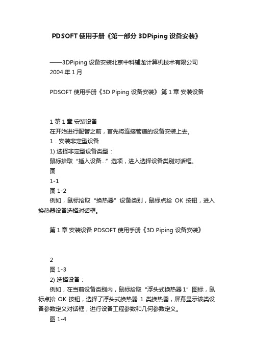
PDSOFT使用手册《第一部分3DPiping设备安装》——3DPiping设备安装北京中科辅龙计算机技术有限公司2004年1月PDSOFT 使用手册《3D Piping 设备安装》第1章安装设备1 第1章安装设备在开始进行配管之前,首先将连接管道的设备安装上去。
1.安装非定型设备1) 选择非定型设备类型:鼠标拾取“插入设备…”选项,进入选择设备类别对话框。
图1-1图 1-2例如,鼠标拾取“换热器”设备类别,鼠标点拾OK 按钮,进入换热器设备选择对话框。
第1章安装设备 PDSOFT 使用手册《3D Piping 设备安装》2图 1-32) 选择设备:例如,在当前设备类别内,鼠标拾取“浮头式换热器1”图标,鼠标点拾OK 按钮,选择了浮头式换热器1类换热器,屏幕显示该类设备参数定义对话框,进行设备工程参数和几何参数定义。
图 1-43) 定义设备工程参数:鼠标点拾工程参数按钮,进入设备工程参数定义对话框,例如,PDSOFT 使用手册《3D Piping 设备安装》第1章安装设备3 在设备名称域内键入浮头式换热器,在设备位号域内键入此台设备在设布置图中的设备位号H101,其它的域内内容暂时不考虑;图 1-54) 定义设备图层:(1) 用统一的设备图层:在“设备图层名称”区域内,鼠标点拾“使用统一图层”,使其处于被选择状态?。
这样,所有设备模型图形都被存放在“EQUIP_MODEL ”层上,所有设备智能线都被存放在“EQUIP_SMRTLN ”层上。
(2) 按设备位号分层:在“设备图层名称”区域内,鼠标点拾“按设备位号分层”,使其处于被选择状态?。
这样,每台设备模型被存放在“EQUIP_”+设备位号+“MODEL ”层上,每台设备智能线被存放在“EQUIP_”+设备位号+“SMRTLN ”层上。
例如,设备H101的模型图层名为“EQUIP_H101_MODEL ”,智能线图层名为第1章安装设备PDSOFT使用手册《3D Piping 设备安装》4“EQUIP_H101_SMRTLN”。
proE4.0管道(piping)教程——修改尺寸

proE4.0管道教程——修改尺寸1 值标注所选特征的尺寸值,用鼠标选取需要标注尺寸的一、特征实体,该特征实体的所有尺寸参数值将全部显示出来; 2 尺寸修饰2.1 格式格式:下面有公称公称公称、极限极限极限、加加-减、对称对称+-、小数小数小数、分数分数6个功能选项,其中小数小数小数:将尺寸以小数形式显示; 分数分数:选取一个尺寸确定,此时要求输入最大分母,2.2 小数位数小数位数:设定尺寸的精度,点击小数位数小数位数小数位数后在消息窗口输入尺寸的小数位数:2,确定,用鼠标点击需要修改的尺寸,将以所设定的尺寸精度显示尺寸,如1000.00;文本后提示选取需文本:编辑尺寸的尺寸公差、形位公差等文本符号,点击文本2.3 文本文本文本符号框和消息输入窗口,同时被选取的尺寸将以要修改的尺寸,选取后弹出文本符号文本符号灰色显示:文本符号栏中选取需要的符号,并设计好尺寸数值后确定。
同一个尺寸可输入从文本符号文本符号一个或一个以上的尺寸文本。
2.4 符号移动尺寸:改变尺寸标注的摆放位置,包括尺寸值在尺寸线上的移动和尺寸2.5 移动尺寸标注整体移动,也可以同时改变。
移动尺寸提示选取1个尺寸项目,用鼠标点击需要移动的尺寸,然后在需要点击移动尺寸移动尺寸放置的位置点击左键,尺寸移动完成。
2.6 移动文本移动文本:将尺寸值在尺寸线上移动,改变值值在尺寸线上的摆放位置,该命令可以实现将尺寸移到尺寸线外进行标注。
如果希望将尺寸移到尺寸线中间,可以使用移动尺寸移动尺寸移动尺寸命令实现,注意移动文本移动文本移动文本命令只能实现尺寸在尺寸线上的移动。
反向箭头:选取需要修改的尺寸将实现尺寸箭头的反向标注。
2.7 反向箭头3 尺寸尺寸:修改选取的一个或多个尺寸,被选取修改的尺寸将以红色显示。
选取尺寸尺寸尺寸后按确定,弹出尺寸属性尺寸属性尺寸属性框,在这里可以对标注尺寸进行编辑,包括尺尺寸修饰寸修饰中的所有命令,是尺寸修饰尺寸修饰尺寸修饰命令的集成:4 设定模型比例设定模型比例:将所有管道模型按照输入的比例值进行缩放,比例值小于1为缩小,比例值大于1为放大,比例值等于1返回原大小,注意比例参照的基准点是笛卡尔坐标系的原点。
proe规范驱动管线报告
关于规范驱动管道中的管线报告“规范驱动管道”允许您创建关于规范驱动管线的各种报告。
可选取管线、管接头或管段以创建报告。
可使用“报告管线”(Report Pipeline)对话框创建下列类型的报告:∙段∙管线∙Fitting∙保温材料∙材料清单∙文件互换格式(FIF)∙示意性的一致性检查∙可指定的报告∙折弯位置报告∙折弯机报告∙孔报告∙时钟角报告此报告显示在“报告管线”(Report Pipeline)对话框或单独的“信息窗口”中。
缺省情况下,还会将其以 .dat 文件的形式保存在工作目录中。
每个报告类型都以标准格式提供。
只能改变“管线网络”报告的格式。
注意:如果管接头规范与管线规范匹配,则不报告该管接头的规范信息。
在规范驱动管道中创建管线报告1.单击“管道”(PIPING)>“信息”(Info)。
“报告管线”(Report Pipeline)对话框打开。
2.单击“类型”(Type)并选取要创建的报告类型。
3.- 段报告4.- 管线报告5.- 管接头报告6.- 保温材料报告7.- 材料清单报告8.- 输出FIF 报告∙- 示意性的一致性检查报告注意:对于此报告设置,将piping_shcematic_driven 配置选项设置为yes。
∙- 可指定的报告∙- 折弯机报告∙- 折弯位置报告注意:将piping_enable_designate_report 配置选项设置为no 时,“折弯机”和“折弯位置”报告可用。
注意:可通过为配置选项default_dec_places 指定一个值,在“折弯位置”报告、“折弯机”报告和“输出FIF”报告中指出小数位数。
缺省值为2。
3.要选取不同的报告格式,可从“选取报告格式”(Select Report Format)列表中选择。
单击创建或编辑报告格式。
注意:仅当选取报告类型为“管线”(Pipeline)时,“选取报告格式”(Select Report Format) 才可用。
proE4.0管道(piping)教程——信息命令
proE 管道教程管道教程——————信息命令信息命令
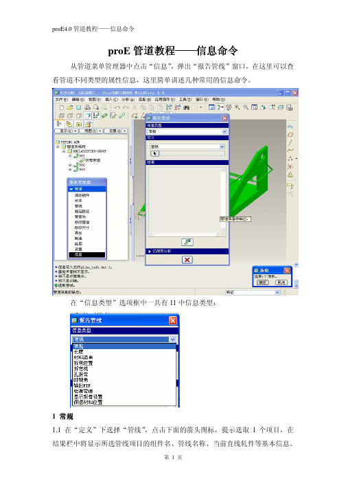
从管道菜单管理器中点击“信息”,弹出“报告管线”窗口,在这里可以查看管道不同类型的属性信息,这里简单讲述几种常用的信息命令。
在“信息类型”选项框中一共有11中信息类型:
1 常规
1.1 在“定义”下选择“管线”
,点击下面的箭头图标,提示选取1个项目,在结果栏中将显示所选管线项目的组件名、管线名称、当前直线轧件等基本信息。
直径、长度、壁厚等信息。
点击图标,“结果”栏中的信息以独立窗口的形式显示。
1.3 如果管道设计有保温材料,在“保温材料”定义项的结果中显示保温材料的相关信息:
2 长度
显示所选管线或管段的长度信息
材料清单:显示所有已定义的管道导管材料清单信息。
3 材料清单
4 折弯位置
在“信息类型”中选取“折弯位置”,用鼠标依次点击管道的中心线、参照坐标系(一般选笛卡尔坐标系)完成选取后,在被选取的管道上出现该管道的流
体流向,也是管道的折弯顺序方向,点击“反向”折弯方向改变,同时折弯位置信息表中的信息顺序也随之改变:
折弯机:给出使用数控弯管设备进行加工时的参数文件。
5 折弯机
欢迎大家登录“中国机械资讯网”我的个人空间进行交流和获取更多的proE4.0学习资料。
网址:/?188912/。
PROE5.0管道config
0、!units_system_dic_file!管道指定包含MCAT 文件名和单位的映射的文件。
1、!pro_pip_fitt_dir!管道指定目录,搜索在Pro/PIPING 中使用的管接头。
2、!pro_pip_lnstk_dir!管道指定用来搜索Pro/PIPING 中所用线栈文件的目录。
要使用完整路径,以避免出现问题。
3!pro_insulation_dir!管道指定搜索Pro/PIPING 中所使用绝缘文件的目录。
使用完整路径名,以避免出现问题。
4、!pipeline_assembly_library_dir!管道设置缺省管线组件库目录。
5、!piping_appearance_map_file!管道设置缺省管道外观映射文件名。
6、!piping_bolt_nut_select_file!管道管道螺栓和螺母选择文件。
7、!piping_end_compatibility_file!管道设置缺省管道端头兼容性文件名。
8、!piping_fitt_category_map_file!管道设置缺省管道装配目录映射文件名。
9、!piping_fitt_library_dir!管道设置缺省管道装配库目录。
10、!piping_insulation_dir_file!管道设置缺省管道绝缘目录文件名。
11、!piping_manufacture_dir_file!管道设置缺省管道制造目录文件名。
12、!piping_material_file!管道设置缺省管道材料文件名。
13、!piping_mcat_dir!管道设置缺省管道主目录路径。
14、!piping_mcat_dir_file!管道设置缺省管道主目录路径文件名。
15、!piping_project_data_dir!管道设置缺省投影数据目录。
16、!piping_schematic_xml_dir!管道指定包含示意图性信息XML 文件的带完整路径的目录。
SP3D_Piping-chinese
Turn Feature
© 2004. Intergraph Corporation. All Rights Reserved.
Port (端口)
是部件上的连接点
Port 1
Port 2
© 2004. Intergraph Corporation. All Rights Reserved.
插入管道部件
交互式插入管道部件 In-line components (Valves, Tees, Reducers); Change of direction (Elbows, Miters, Bends); End Components (caps and plugs); Strainers (Y-strainers, Basket Strainers) etc…
Straight Feature Pipe
© 2004. Intergraph Corporation. All Rights Reserved.
管道布置命令
一个 Pipe Run 的起点可以是: - 设备上的被定义成连接管道的管口 - 空间上的一个点 - 在一根已经存在的 pipe run 上的点
© 2004. Intergraph Corporation. All Rights Reserved.
SmartSketch
© 2004. Intergraph Corporation. All Rights Reserved.
利用 PinPoint 命令布置管线
PinPoint 提供了坐标值的输入命令 x,y,z 的坐标点与 Target Point 相关联 Target point 可被定义为: • Global origin (全局坐标原点) • User selected coordinate system (指定坐标系远点 • User defined point in space(空间上的一个点)
piping_2(5.0)proe5.0 管道设计(下)
1
2
3
4
管路BOM.
1
For 常州液压,严禁传播
2
3
创建表格 同样定义重复区域 参数为
(1)
(2) (3)asm.mbr.pipe.segment.len.pre_cut 更新表格
管路BOM.
管路BOM.
得到的BOM表如右图
For 常州液压,严禁传播
管路配置选项
pipe_3D_bend_theor_int_pts yes no 在三维管道模型中显示理论相交点。 pipe_extend_dim_scheme Cartesian, cylindrical, spherical 指定管道延伸段的标注形式。 pipe_solid_centerline(非规范驱动) yes, no 是否显示管道实体中心线 pro_pip_fitt_dir 指定fitting的路径 pro_pip_lnstk_dir 指定管线规格的路径 piping_design_method(非规范驱动) non_spec_driven、spec_driven、user_driven 指定管道工程的管道设计方法。 •non_spec_driven - 激活“非规范驱动”管道设计模式。 •spec_driven - 激活“规范驱动”的管道设计模式。 •user_driven - 激活“用户驱动”的管道设计模式。
Pro/ENGINEER培训
•Piping
信息查看
应用程序 >进入管路模块
For 常州液压,严禁传播
活动装配> 选择 asm_pipe.asm 信息 > 管道 > 长度 > 全选>完成>信息显示如下
信息查看
我们可以在报告管线中,查看 管线库 或者 段 的信息
ProENGINEER Pipe管道教程
第十一章管道的绘制使用PROE创建三维管道一般有三种方法:第一种方法、3维曲线扫描:先绘制一条曲线,然后再以这条曲线为中心线进行扫描成管道状的实体,这个零件的轨迹是空间的,所以不推荐使用扫描来实现。
第二种方法、“插入”高级特征:仅仅是个特征有一定的局限性,比如只能在零件模式下使用,装配模块是出不来管道实体的。
第三种方法、使用管道模块:功能强大优势明显,工艺上,多数管道都是在各零件安装定位后安装,我们设计也是如此,因此管道(piping)只能在装配模式下才可以调用是明智的。
优点如下:(1)方便定义管理多种管线。
(2)布线方法多样、灵活、方便。
(3)方便提取管道信息。
(4)适合于管路复杂的装配设计。
下面以几个实例来讲述管道的建模过程。
实例一:使用“插入”高级特征绘制管道。
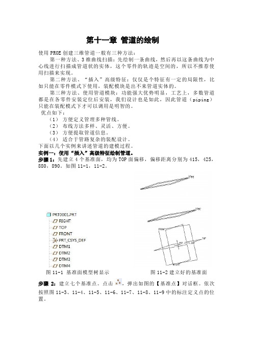
步骤1:先建立4个基准面,均为TOP面偏移,偏移距离分别为415,425,880,890。
如图11-1,11-2。
图11-1 基准面模型树显示图11-2建立好的基准面步骤2:建立七个基准点。
点击,弹出如图的【基准点】对话框。
依次按照图11-3、11-4、11-5、11-6、11-7、11-8、11-9中的标注定义点的位置。
图11-3 PNT0的定位图11-4 PNT1的定位图11-5 PNT2的定位图11-6 PNT3的定位图11-7 PNT4的定位图11-8 PNT5的定位图11-9 PNT6的定位七个基准点建立完毕。
步骤3:选择【插入】→【高级】→【管道】命令。
如图11-10。
图11-10 【管道】命令的选取弹出如图11-11菜单管理器图11-11选取管道命令后弹出的【菜单管理器】点击【完成】,在消息框里输入管道的外部直径25,如图11-12。
图11-12 输入外部直径接着输入侧壁厚度2,如图11-13。
图11-13 输入侧壁厚度在随后弹出的菜单管理器选择依次【单一半径】【整个阵列】【添加点】,如图11-14。
图11-14【连接类型】设置然后再依次选择基准点,顺序为PNT0→PNT1→PNT2→PNT3→PNT4→PNT5→PNT6。
ProE管道建模的三种方法:扫描、高级管道、管道模块
Pro/E管道建模的三种方法:扫描、高级管道、管道模块没有接触管道时,感觉管道建模很复杂,其实真正去应用的时候,并没有想象得那么难。
这里我们一起来探讨管道建模,相信你也一定能行。
通常创建管道有三种方法:曲线扫描:这其实是用普通特征来创建管道,建管道比较麻烦;插入→高级→管道:有一定的局限性,比如只能在零件模式下使用,装配模式是出不来管道实体的;应用程序→管道:这是管道模块,功能强大优势明显:如工艺上,多数管道都是在各零件安装定位后安装,与实际设计理念相同。
下面就针对这三种管道建模方法进行探讨,重点放在第三种Pro/E管道模块上。
所用版本为Pro/E4.0 m050。
本教材地址:Pro/E管道建模的三种方法:扫描、高级管道、管道模块目录第一种方法:扫描特征 (2)第二种方法:高级管道 (7)第三种方法:管道模块 (12)规范驱动 (22)保温材料 (36)实例 (40)Pro/E技术资料、光盘、书籍汇总 (48)三维网 XinYaZhu2009-5-4第一种方法:扫描特征使用传统的零件创建曲线,扫描成实体的方法。
先绘制一条曲线,然后再以这条曲线为中心线进行扫描成管道状的实体,如果管道中心线是空间的,那么轨迹曲线的创建就比较复杂了。
这种方式可以在零件模式和组件模式两种模式下创建。
这里举一空间管道为例进行说明。
1、在一基准面中草绘曲线12、在与上一基面垂直的基准面中草绘曲线2这是两条曲线的空间位置3、我们要利用这两个平面曲线生成空间曲线。
按住CTRL选中这两条曲线;编辑→相交生成所需要的管道空间曲线4、插入→扫描→伸出项选择相交曲线作为轨迹曲线进入管道截面界面,绘制两个圆形,代表管道的外径和内径退出截面,确定,得到如图所示的管道。
实例part:pipe.rar (214.83 KB)第二种方法:高级管道使用零件中的管道特征创建。
这种方式可以在零件模式和组件模式两种模式下创建。
下面以一个变形的晾衣架为例说明高级管道的创建。
- 1、下载文档前请自行甄别文档内容的完整性,平台不提供额外的编辑、内容补充、找答案等附加服务。
- 2、"仅部分预览"的文档,不可在线预览部分如存在完整性等问题,可反馈申请退款(可完整预览的文档不适用该条件!)。
- 3、如文档侵犯您的权益,请联系客服反馈,我们会尽快为您处理(人工客服工作时间:9:00-18:30)。
Compression_top_level.ASM 7. 单击 工具 > 选项 并单击 打开一个配置文件 8. 单击回到上一级目录(piping_wf5_tutorial)选择 config.pro 文件 9. 单击打开 和 确定 装载管道配置文件.
5. 单击 完成 。
插入管接头
任务 7. 在已布置管道的起始端放置一个法兰配件。
1. 单击 管接头
> 终止。
2. 回到上一级目录,打开 flange 文件夹,选择 FLANGE_NECK_RF 零
件,单击 打开。 3. 选择 FLANGE_NECK_RF-STEEL-20K-150 实例,打开。 4. 选择管道端点起点
。
7. 从子组件 RESERVOIR_F 中的零件 FLANGE_SLIP_RF-STEEL 上
选择 PORT0 做为起点。
9. 单击 延伸 。
10. 选择 沿坐标系轴 类型。 11. 选择 Z-轴箭头,按住左键向正 Z 方向拖动管线到大约 900。 12. 延伸尺寸选项从 长度 改为 距参照的偏移 。 13. 选择子组件 TANK_B 中的零件
目标
通过这个指南你将学会:
手动管路设计 (非规范驱动) ; 基于规范的自动管路设计; 基于原理图的自动管路设计 管路文档: Standard 和 Isometric。
开始之前
这个指南创建于 Pro/ENGINEER Wildfire 5.0 M010 版本中。
继续之前确保你的电脑上安装了 Pro/ENGINEER Wildfire 5.0 软件。如果没有 安装请联系相关的培训讲师。
任务 1. 设置工作目录,加载 piping_config.pro 配置文件。
1. 如果需要启动 Pro/ENGINEER Wildfire 5.0。 如果 Pro/ENGINEER 已经运行要确保全部窗口关闭,清除内存中前面操
作用到的文件。 2. 在文件夹导航器,浏览到下列资料夹…\piping_wf5_tutorial。 3. 在练习 1 资料夹 Exercise1 上右击设置工作目录。
任务 11. 由 Leg-1 管道创建实体零件。
1. 单击 制造 。 2. 单击 管道实体 。 3. 在管道实体对话框中单击 视图 > 全部展开。 4. 单击 全选 。 5. 在复制自处单击 打开 ,浏览到 piping_specs 资料夹,打开 start
资料夹,单击打开。 6. 选择 pipe_solid_start.prt 为 复制自 选项,单击应用 。 7. 单击 生成,然后单击 关闭。
6. 选择 。
任务 6. 在已布置管道的拐角插入一个弯头。
1. 单击 管接头
> 拐角。
2. 点击工作目录 ,回到上一级目录,打开 piping_specs\fittinglib\elbow 文件夹,选择 ELBOW_90_BW 零件,点击打开。
3. 选择 ELBOW_90_BW-STEEL-L-150 实例,点击 打开。 4. 选择下图所示管道端点。
练习 2: 用布线规范驱动管线
目标
成功完成这个练习后,你将知道:
关联一条管道到规范。 创建规范驱动管道。
场景
在这个练习中,你将从储水罐(Reservoir G)到冷却器(Cooler)布置一条管 道,使用项目规范数据决定设计规则和选用指定管接头配件。你将使用动态设计 规则检查功能检查设计违规。
3. 选择 RED_CON_BW-STEEL-150X100 实例,单击 打开。 4. 选择图示管道段。
5. 单击 准确长度 ,输入 500。 6. 在子窗口中选择基准点 PNT0。 7. 单击完成。
注意所选的入口端(PORT_0 或 PORT_1)决定了管道上管接 头配件的方向,系统确定方向时,以所选坐标系的 Z 轴对齐 现有管道。
9. 单击 管接头
> 终止。
10. 从 piping_specs/flange 目录中选择 FLANGE_NECK_RF 零件,
单击打开。 11. 选择 FLANGE_NECK_RF-STEEL-20K-100 实例,单击打开。 12. 选择图示管道端点。
15. 从管接头子窗口中选择 PORT1。
管路基础
Pro/Piping 能够使你进行 3-D 管路设计,同时管路设计还是整个产品研发流程 的一部分,能够实现与设计中其它部分之间的相互关联。Pro/Piping 用于在 Pro/Engineer 组件环境(通常是设备装备)中以参数化的方式创建实体管道零 件。管路设计可以是规范驱动或非规范驱动。 规范驱动设计方式包含了管道设计规范和建模任务自动化,这种方法用于工厂、 造船和航空方面的管路设计。非规范驱动设计方式主要采用手工任务的方式创建 管路系统,通常用于设计简易或比较灵活的管路系统。 另外,来自于布线系统设计师的管道和仪表流程图(P&ID)中的 2-D 原理图设计 信息能够用于 Pro/ENGINEER 中的 3-D 管路设计中。 完成下面四个不同练习后将会提高你对 Pro/Piping 的使用技能以及对 Pro/Piping 的理解。根据管道的设计规格和实际应用,你可以选择使用 Pro/Piping 中的一种或多种方法来进行设计。
1. 选择 已命名的视图列表 ,选择 Manual_Pipe 视图。
2. 插入 > 管道 > 管线 。 3. 在提示时输入 LEG-1 。 4. 在弹出的管线库列表中选择 PIPE_150A。
当创建管线时你应该采用一个有意义的名称。在必要时启用或禁用基准特 征的显示,在这个练习中将 不再特别说明。
练习开始之前请下载相应的模型文件。 把文件解压到你的本地硬盘。 启动 Pro/ENGINEER 进入 Pro/Piping 模块。 设置你的工作目录到这个位置。
例如:C:\users\piping_wf2_tutorial
建议你通过设置屏幕分辨率使你屏幕工作区域最大化,例如 1600x1200。
任务 3. 为 Leg-1 组件创建必需的管线库(原始管材参数文件)。
1. 单击 应用程序 > 管道。 2. 在模型树中选择 LEG-1.ASM,RMB,激活。
全部管道特征将创建于激活组件中,最佳做法是创建一个专门的管道组 件,而不是直接创建在顶级 组件下面。
4. 编辑 > 设置 > 管线库 > 创建。 5. 输入 PIPE_150A 做为名称。 6. 配置管线库对话框如下图所示。
任务 1. 打开压缩机组件 Compression_top_level.ASM。
1. 如果需要启动 Pro/ENGINEER Wildfire 5.0。 如果 Pro/ENGINEER 已经运行要确保全部窗口关闭,清除内存中前面操 作用到的文件。
2. 在文件夹导航器,浏览到下列资料夹…\piping_wf5_tutorial. 3. 在练习 1 资料夹 Exercise1 上右击设置工作目录。 4. 选择 COMPRESSION_TOP_LEVEL.ASM 预览模型,单击打开。 5. 在主工具条中单击已保存的视图列表 , 选择 Manual_pipe. 6. 如需要, 打开坐标系显示 .
任务 9. 修改管道规格。
插入的管接头配件
1. 选择 修改管线 。
2. 选中管线库 按钮。 3. 选择图示管线
4. 单击 确定。 5. 修改管线库值为 PIPE_100A。 6. 点击 。
任务 10. 查看模型树中创建的特征。
1. 如果需要,展开 LEG-1.ASM 组件。注意创建的管道特征。
2. 确保 LEG-1.ASM 仍旧是当前激活组件,绿色星星符号标识。 激活组件的方式与标准组件模式中相同。
PIPE_150A 管线
For shape type and corner type the check boxes configure selectable options, the green ball selection configures the default selection.
7. 单击 保存 。 8. 选 exercise1 资料夹,确定。
FLANGE_NECK_RF-STEEL-20K-100 上的坐标系 Port0。
14. 投影值输入 0 。 15. 单击确定完成延伸。
16. 选择 至 点/端口 。 17. 选择子组件 TANK_B 中的零件
FLANGE_NECK_RF-STEEL-20K-100 上的坐标系 Port0。点击
完成连接。
9. 单击 。 10. 单击 读取. 11. 如果需要单击 工作目录 ,然后到上一级目录,打开
piping_specs\linestocks 文件夹,选中图示 5 个文件。
12. 单击 打开,然后单击 完成/返回 。 13. 在模型树中展开 LEG-1.ASM。 14. 注意管线库特征。
任务 4. 创建一条从储水塔法兰到水箱法兰的 150A 管道。
练习一:手动管路设计
目标
成功做完这部分练习后,你将学会如何进行: 用手动的方法进行管路设计 在一个管道中插入不同类型的配件
场景
你正在为一个压缩机单元设计新的管路系统,这涉及到压缩机中冷却水路管道系 统的设计。在这个练习中,你将手动设计一条从 Reservoir_F(储水塔)到 Tank_B(水箱)的管线。你将使用手动管道设计方法并插入几种类型的配件。
Pro/Piping 培训指南
简介
欢迎来到 Pro/Piping 的世界。目前很多企业管路系统的设计和制造都是一个人 工作业的流程,为了有效的进行管路设计,需要构建原型样机。这不仅仅是在成 本方面代价昂贵,同时也是一个耗时且易于出错的过程。Pro/Engineer 管路设 计提供了一种解决方案,它可以在已有的电子机械零件三维数字模型的基础上设 计管路系统并制作相关联的工艺文档。这个指南通过三种不种的方法进行管路设 计,以便我们能够针对大型或小型管路系统,采用相应的满足用户要求的设计方 法。