Keysight 高速数字化仪 (PXI 和 AXIe)
基于PXI总线的高速数字化仪的设计和实现
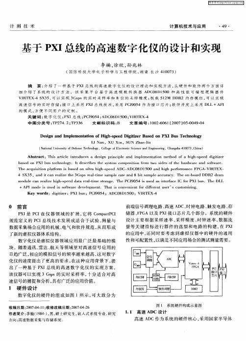
高 速 信 号 的 实 时存 储 ; 口上 采 用 P 接 XI总 线 技 术 , 用 P 9 5 采 CI0 4作 为 接 口芯 片 ; 件 开 发 上 采 用 D L+AP 软 L I
摘 要 : 绍 了 一 种 基 于 P 介 XI总 线 的 高 速 数 字 化 仪 的 设 计 理 论 和 实 现 方 法 , 硬 件 和 软 件 两 个 方 面 详 从
细 介 绍 了 系 统 的 设 计 方 法 。 该 采 集 平 台 基 于 高 速 模 数 转 换 器 AD 0 D1 0 和 高 性 能 可 编 程 逻 辑 器 件 C 8 50
维普资讯
计 测 技 术
计 算机 技 术与应 用
・ 9・ 4
基于 P I X 总线 的高速数字化仪 的设 计和实现
李楠 , 徐欣 , 兆林 孙
(国 防 科 技 大 学 电 子 科 学 与 工 程 学 院 , 南 长 沙 41 0 3) 湖 07
( ao a U i rt o ees eh ooy ol eo lc oi S i c n nier g C agh 10 3 C ia N t nl nv s y f f eT cnlg .C lg fEet nc ce eadE gnei , hn sa4 0 7 , hn ) i e i D n e r n n
Ke r y wo ds:d g tz r i iie ;PXI b s;PCI 0 4 ;ADC0 00;VI u 9 5 8D1 5 RTEX- 4
PXI技术的回顾、现状和展望

PXI技术的回顾、现状和展望PXI 技术概览PXI(PCI eXtensions for Instrumentation)不仅是一个总线技术,同时也是一个基于PC 技术的模块化I/O 的标准,为基于PC 的自动化测试测量与控制系统架构添加了集成的定时和同步功能、工业级的坚固设计、以及更多的通道数。
自1997 年由NI 公司提出以来,现在PXI 已经成为一个受到全球超过60 家厂商共同支持的标准。
在PXI 标准中,针对模块化仪器和CPU 之间数据传输的核心内部数据总线是带宽达到132MB/s 的PCI 总线。
此外,PXI 标准设计中需要一个专用的定时和触发总线,以进行不同模块之间的同步。
使用PXI 架构,用户可以得益于PC 技术的低成本、易用性以及灵活性,并且便于随PC 技术发展为系统进行性能升级。
无论您是准备构建一个仪器平台、数据采集系统、自动化测试系统、工业自动化系统、或是实时控制系统,PXI 的开放式工业标准特性都能够帮助降低系统的总成本和开发时间,增强系统性能和带宽,使系统集成工作变得轻松简单,同时确保系统具有长期可维护性。
PXI 的广泛应用PXI 标准由PXI 系统联盟(PXISA)进行管理,这是一个由世界各地超过60 家公司共同签约的联盟,其宗旨是为了推动PXI 标准的应用,保证标准的交互操作性,并维护PXI 规范。
随着PXI 已成为一个标准平台,一些世界领先的测试系统供应商也将他们的测试解决方案转向PXI 平台,包括Agilent 在内的许多测试设备厂商均已将PXI 视为模块化仪器的主流标准。
60 余家PXISA 成员现在提供超过1500 种PXI 外围模块,包括模拟和数字I/O、高速仪器、视觉系统、运动控制、各类总线接口、以及基于FPGA 可。
GPIB、VXI、PXI、LXI仪器自动测试系统的应用及发展

GPIB、VXI、PXI、LXI仪器自动测试系统的应用与发展一、自动测试系统和测试总线的基本概念自动测试系统(Automatic Test System,ATS)指的是以计算机为核心,在程序控制下,自动完成特定测试任务的仪器系统。
与传统测试仪器不同,自动测试系统强调在计算机的控制下,由若干可程控的通用设备共同完成测试任务。
AST首先要解决的关键问题是程控设互相协议的问题,也就是接口总线问题。
测试总线是指可以应用在测试、测量和控制系统中的总线。
在专用测试设备中的总线包括GPIB (General Purpose Interface Bus)、VXI(VMEbus eXtensions for Instrumentation)、PXI(PCI eXtensions for Instrumentation)、LXI(LAN eXtensions for Instrumentation)等总线。
二、基于GPIB总线技术的自动测试系统1、GPIB发展历程最初的GPIB是在1960年代后半期由惠普(当时称为HP-IB)开发的,用于连接和控制惠普制造的可编程仪器。
在引进了数字控制器和可编程测试设备之后,对来自多个厂商的仪器和控制器之间进行标准高速通信接口的需求也应运而生。
在1975年,美国电气与电子工程师学会(IEEE)发布了ANSI/IEEE标准488-1975,即用于可编程仪器控制的IEEE标准数字接口,它包含了接口系统的电气、机械和功能规。
最初的IEEE 488-1975在1978年经过修改,主要是出版声明和附录方面。
现在这个总线已经在全世界围被使用,它有三个名字:•通用接口总线(GPIB)•惠普接口总线(HP-IB)•IEEE 488总线由于最初的IEEE 488文档并没有包含关于使用的语法和格式规的叙述。
这部分工作最终形成了一个附加标准IEEE 488.2,用于IEEE 488(被更名为IEEE 488.1)的代码、格式、协议和通用指令。
Keysight PXI-5922 24位高灵活度PXI数字波形仪说明书
SPECIFICA TIONSPXI-592224-Bit, Flexible Resolution PXI OscilloscopeContents Definitions (2)Conditions (2)Vertical (2)Analog Input (2)Impedance and Coupling (3)V oltage Levels (3)Accuracy (3)Bandwidth and Transient Response (4)Spectral Characteristics (6)Skew, Input Bias Current (9)Settling Time (10)Horizontal (11)Sample Clock (11)Onboard Clock (Internal VCXO) (11)Phase-Locked Loop (PLL) Reference Clock (12)Trigger (13)Reference (Stop) Trigger (13)External Trigger (14)PFI 0 and PFI 1 (Programmable Function Interface, AUX Front Panel Connectors) (14)Waveform Specifications (15)Calibration (16)Software (16)Driver Software (16)Application Software (16)Interactive Soft Front Panel and Configuration (16)TClk Specifications (17)Power (17)Physical (18)Environment (18)Operating Environment (18)Storage Environment (18)Shock and Vibration (19)Compliance and Certifications (19)Safety (19)Electromagnetic Compatibility (19)CE Compliance (20)Online Product Certification (20)Environmental Management (20)DefinitionsWarranted specifications describe the performance of a model under stated operating conditions and are covered by the model warranty. Warranted specifications account for measurement uncertainties, temperature drift, and aging. Warranted specifications are ensured by design, or verified during production and calibration.The following characteristic specifications describe values that are relevant to the use of the model under stated operating conditions but are not covered by the model warranty.•Typical specifications describe the performance met by a majority of models.•Nominal specifications describe an attribute that is based on design, conformance testing, or supplemental testing.•Measured (meas) specifications describe the measured performance of a representative model.Specifications are Typical unless otherwise noted.ConditionsSpecifications are valid under the following conditions unless otherwise noted.•Full operating temperature range•All impedance selections•All sample rates•Source impedance ≤50 ΩSpecifications are valid under the following conditions unless otherwise noted:•Ambient temperatures of 15 °C to 35 °CVerticalAnalog InputNumber of channels Software-selectable: two simultaneouslysampling, single-ended or unbalanceddifferential channels or one differential channel Connector BNC2| | PXI-5922 SpecificationsImpedance and CouplingInput impedance Software-selectable: 50 Ω ±2.0% or 1 MΩ±2.0% in parallel with a nominal capacitanceof 60 pFInput coupling AC, DC, GNDVoltage LevelsFull-scale (FS) input range±1 V (2 V pk-pk)±5 V (10 V pk-pk)Maximum input overload50 Ω7 V rms with |Peaks| ≤10 V1 MΩ|Peaks| ≤42 VAccuracyDC accuracy, Warranted12 V pk-pk range±(0.05%) of input + 50 μV)10 V pk-pk range±(0.05%) of input + 100 μV)DC drift, nominal22 V pk-pk range±(.002% of input + 5 μV per °C)10 V pk-pk range±(.002% of input + 10 μV per °C)1 1 MΩ input impedance; within ±5 °C of self-calibration temperature; ppm = parts per million (1 ×10 -6 ).2 1 MΩ input impedance.PXI-5922 Specifications| © National Instruments| 3AC amplitude accuracy 0.06% at 1 kHz 3Crosstalk 4At 100 kHz ≤-110 dB At 1 MHz ≤-100 dB At 6 MHz≤-80 dBCommon-mode rejection ratio (CMRR)50 dB up to 1 kHz 5Figure 1. PXI-5922 CMRR with Differential T erminal Configuration, Measured100 k1 M 10 M10 k 1001 k –40–50–60–70–80–90–100C M R R (d B)Frequency (Hz)Bandwidth and Transient ResponseAlias-free bandwidth0.4 × Sample Rate63 1 MΩ input impedance; within ±5 °C of self-calibration temperature.4CH 0 to/from CH 1, External Trigger to CH 0 or CH 1.5Unbalanced differential input terminal configuration.6Input frequencies ≥ 0.6 × Sample Rate .4 | | PXI-5922 SpecificationsTable 2. Alias Protection 6 (Continued)AC coupling cutoff (-3 dB)90 Hz7Figure 2. 100 kS/s Frequency Response, MeasuredFrequency (Hz)20 k 30 k 10 k40 k0.2–0.2–0.100.1P h a s e (d e g r e e s )Frequency (Hz)10 k20 k 30 k 40 k50 k0.2–0.2–0.100.1A m p l i t u d e (d B )6Input frequencies ≥ 0.6 × Sample Rate .7Referenced to DC; input frequencies up to 0.4 × Sample Rate .PXI-5922 Specifications | © National Instruments | 5Figure 3. 1 MS/s Frequency Response, MeasuredFrequency (Hz)0200 k 300 k 100 k400 k0.2–0.2–0.100.1P h a s e (d e g r e e s )Frequency (Hz)100 k200 k 300 k 400 k500 k0.2–0.2–0.100.1A m p l i t u d e (d B )Figure 4. 10 MS/s Frequency Response, MeasuredFrequency (Hz)2 M3 M 1 M4 M1–1–0.500.5P h a s e (d e g r e e s )Frequency (Hz)1 M2 M3 M4 M5 M0.2–0.2–0.100.1A m p l i t u d e (d B )Spectral Characteristics88-1 dBFS input signal; Sample Rate is 10 × input frequency; within ±2 °C of self-calibration temperature.6 | | PXI-5922 SpecificationsFigure 5. PXI-5922 Dynamic Performance with 10 kHz Input Signal, Measured,1 M Ω,10 V pk-pk Range, 500 kS/s, Unbalanced Differential, 10,000-Point FFT with 10 Averages–200–40–60–80–100–120–140–160255075100125150175200225250A m p l i t u d e (dB F S )Frequency (kHz)Figure 6. PXI-5922 Dynamic Performance with 10 kHz Input Signal, Measured, 1 M Ω,2 V pk-pk Range, 100 kS/s, Unbalanced Differential, 10,000-Point FFT with 10 Averages50454035302520151050–20–40–60–80–100–120–140–160A m p l i t u d e (dB F S )Frequency (kHz)PXI-5922 Specifications | © National Instruments | 7Table 5. Total Harmonic Distortion (THD)910Table 7. Signal-to-Noise Ratio (SNR) without Harmonics119-1 dBFS input signal; includes the second through the fifth harmonics; within ±2 °C of self-calibration temperature .10-1 dBFS input signal; input frequency is 0.1 × Sample rate; within ±2 °C of self-calibration temperature; calculated from THD and RMS noise.11-1 dBFS input signal; input frequency is 0.1 × Sample rate; within ±2 °C of self-calibration temperature; calculated from SINAD and THD.8| | PXI-5922 SpecificationsTable 8. RMS Noise, Warranted 12Figure 7.PXI-5922 Noise Density, MeasuredN o i s e D e n s i t y (d B F S /H z )Frequency (Hz)Skew, Input Bias CurrentChannel-to-channel skew 13≤500 psInput bias current 14≤500 nA, Warranted12100 Hz to 0.4 × Sample rate ; DC coupling; input 50 Ω terminated.13 1 MHz input, 5 MS/s sample rate.14Within ±5 °C of self-calibration temperature.PXI-5922 Specifications | © National Instruments | 9Settling Time15Figure 8.PXI-5922 Step Response Using Different Filter T ypes, Measured 172.0 µ1.8 µ1.6 µ1.4 µ1.2 µ1.0 µ800 n 600 n 400 n 200 n 03.53.02.52.01.51.00.50.0–0.5Time (seconds)A m p l i t u d e (V )15For a 3 V step from 0 V DC, excluding noise; time referenced to 1.5 V (50%) trigger; applies to 15 MS/s sample rate only.16To set or change the filter type, use the Flex FIR Antialias Filter Type property or the NISCOPE_ATTR_FLEX_FIR_ANTIALIAS_FILTER_TYPE attribute.17Time (t= 0) represents the actual time the edge arrived at the BNC connector on the NI 5922.10 | | PXI-5922 SpecificationsFigure 9. PXI-5922 Frequency Response Using Different Filter Types, Measured100–90–80–70–60–50–40–30–20–10–100A m p l i t u d e (dB )Frequency (Hz)HorizontalSample ClockSourcesInternal onboard clock (internal VCXO)18Onboard Clock (Internal VCXO)Sample rate range, real-time sampling (single shot)1950 kS/s to 15 MS/sPhase noise density (5 MHz input signal)At 10 kHz <-133 dBc/Hz At 100 kHz <-145 dBc/HzSample clock jitter 20≤3 ps rms (100 Hz to 1 MHz)Timebase frequency120 MHz 18Internal Sample clock is locked to the Reference clock or derived from the onboard VCXO.19Available rates are (60 MS/s) /n where n is an integer value from 4 to 1200. The Sample clock period is n/(60MS/s).20Includes the effects of the converter aperture uncertainty and the clock circuitry jitter; excludes trigger jitter.Timebase accuracyNot phase-locked to Reference clock±50 ppm, WarrantedPhase-locked to Reference clock Equal to the Reference clock accuracy Sample clock delay range±1 Sample clock periodSample clock delay resolution400 psPhase-Locked Loop (PLL) Reference ClockReference clock sources PXI_CLK 10 (backplane connector)CLK IN (front panel SMB connector) Frequency range 1 MHz to 20 MHz in 1 MHz increments21;must be accurate to ±50 ppmDuty cycle tolerance45% to 55%Exported Reference clock destinations CLK OUT (front panel SMB connector)PFI <0..1> (front panel 9-pin mini-circularDIN connector)PXI_TRIG <0..6> (backplane connector) CLK IN (Reference Clock Input, Front Panel Connector)Input voltage range Square wave: 0.2 V pk-pk to 1 V pk-pk Maximum input overload7 V rms with |Peaks| ≤ 10 VImpedance50 ΩCoupling ACCLK OUT (Reference Clock Output, Front Panel Connector) Output impedance50 ΩLogic type 5 V CMOSMaximum drive current±50 mA21The default value is 10 MHz.T riggerReference (Stop) TriggerTrigger types EdgeWindowHysteresisDigitalImmediateSoftwareTrigger sources CH 0CH 1TRIGPXI_Trig <0..6>PFI <0..1>PXI Star TriggerRTSI <0..6>SoftwareTime resolution Sample clock periodRearm time144 × Sample clock period22Holdoff Up to (232 - 1) × Sample clock period Related InformationRefer to the NI High-Speed Digitizers Help for more information about the sources available for each trigger type.Analog TriggerTrigger types EdgeWindowHysteresisSources23CH 0 (front panel BNC connector)CH 1 (front panel BNC connector)TRIG (front panel BNC connector)Trigger level range100% FS22Holdoff set to 0.23TRIG is an analog edge trigger only.Edge trigger sensitivityCH 0, CH 12% FSTRIG (external trigger)0.3 V pk-pk up to 1 MHzJitter Sample clock periodDigital TriggerTrigger type DigitalSources PXI_TRIG <0..6> (backplane connector)PFI <0..1> (front panel 9-pin DIN connectorPXI Star Trigger (backplane connector) External T riggerSource TRIG (front panel BNC connector) Impedance100 kΩ in parallel with 52 pF, nominal Input voltage range±2.5 VCoupling DCLevel accuracy±0.3 V up to 100 kHzMaximum input overload|Peaks| ≤42 VPFI 0 and PFI 1 (Programmable Function Interface, AUX Front Panel Connectors)Connector9-pin mini-circular DINDirection BidirectionalAs an Input (T rigger)Destinations Start trigger (acquisition arm)Reference (stop) triggerArm Reference triggerAdvance triggerInput impedance150 kΩ , nominalV IH 2.0 VV IL0.8 VMaximum input overload-0.5 V, 5.5 VMaximum frequency25 MHzAs an Output (Event)Sources Start trigger (acquisition arm)Reference (stop) triggerEnd of RecordDone (end of acquisition)Output impedance50 ΩLogic type 3.3 V CMOSMaximum drive current±24 mAMaximum frequency20 MHzWaveform SpecificationsOnboard memory size8 MB/channel 2 MS/channel32 MB/channel8 MS/channel256 MB/channel64 MS/channelMinimum record length 1 SampleNumber of pretrigger samples0 up to full Record Length for both single-record mode and multiple-record mode Number of posttrigger samples0 up to full Record Length for both single-record mode and multiple-record mode Maximum number of records in onboard memory248 MB/channel13,10732 MB/channel52,428256 MB/channel100,000Allocated onboard memory per record(Record Length × 4 bytes/S) + 400 bytes,rounded up to next multiple of 128 bytes or640 bytes, whichever is greater 24It is possible to exceed these numbers if you fetch records while acquiring data. For more information, refer to the NI High-Speed Digitizers Help.CalibrationSelf-calibration Self-calibration is done on software command.The calibration corrects for gain and offset forall input ranges, input bias current, andnonlinearities in the ADCs.External calibration (factory calibration)The external calibration calibrates the VCXOand the voltage reference. Appropriateconstants are stored in nonvolatile memory. Interval for external calibration 2 yearsWarm-up time15 minutesSoftwareDriver SoftwareDriver support for this device was first available in NI-SCOPE 2.8.NI-SCOPE is an IVI-compliant driver that allows you to configure, control, and calibrate the PXI-5922. NI-SCOPE provides application programming interfaces for many development environments.Application SoftwareNI-SCOPE provides programming interfaces, documentation, and examples for the following application development environments:•LabVIEW•LabWindows™/CVI™•Measurement Studio•Microsoft Visual C/C++•.NET (C# and )Interactive Soft Front Panel and ConfigurationWhen you install NI-SCOPE on a 64-bit system, you can monitor, control, and record measurements from the PXI-5922 using InstrumentStudio.InstrumentStudio is a software-based front panel application that allows you to perform interactive measurements on several different device types in a single program.Note InstrumentStudio is supported only on 64-bit systems. If you are using a 32-bit system, use the NI-SCOPE–specific soft front panel instead of InstrumentStudio. Interactive control of the PXI-5922 was first available via InstrumentStudio inNI-SCOPE 18.0 and via the NI-SCOPE SFP in NI-SCOPE 2.2. InstrumentStudio and the NI-SCOPE SFP are included on the NI-SCOPE media.NI Measurement & Automation Explorer (MAX) also provides interactive configuration and test tools for the PXI-5922. MAX is included on the driver media.TClk SpecificationsYou can use the NI TClk synchronization method and the NI-TClk driver to align the Sample clocks on any number of supported devices, in one or more chassis. For more information about TClk synchronization, refer to the NI-TClk Synchronization Help, which is located within the NI High-Speed Digitizers Help. For other configurations, including multichassis systems, contact NI Technical Support at /support.Intermodule SMC Synchronization Using NI-TClk for Identical ModulesSpecifications are valid under the following conditions:•Any number of PXI modules installed in one NI PXI-1042 chassis.•All parameters set to identical values for each SMC-based module.•Sample clock set to 15 MS/s and all filters disabled.Skew25500 psAverage skew after manual adjustment<10 psSample clock delay/adjustment resolution≤5 psRelated InformationFor information about manual adjustment, refer to the Synchronization Repeatability Optimization topic in the NI-TClk Synchronization Help within the NI High-Speed Digitizers Help.For additional help with the adjustment process, contact NI Technical support at / support.PowerCurrent draw+3.3 VDC 2.0 A+5 VDC 1.4 A+12 VDC330 mA-12 VDC280 mATotal power20.9 W25Caused by clock and analog path delay differences. No manual adjustment performed.PhysicalDimensions3U, one-slot, PXI/cPCI module21.6 cm × 2.0 cm × 13.0 cm(8.5 in × 0.8 in × 5.1 in)Weight336 g (11.8 oz)EnvironmentMaximum altitude2,000 m (at 25 °C ambient temperature) Pollution Degree2Indoor use only.Note To ensure that the PXI-5922 cools effectively, follow the guidelines in theMaintain Forced-Air Cooling Note to Users included in the kit or available at/manuals. The PXI-5922 is intended for indoor use only. Operating EnvironmentAmbient temperature range0 °C to 55 °C in all NI PXI chassis except thefollowing: 0 °C to +45 °C when installed in anNI PXI-1000/B or PXI-101x chassis. (Tested inaccordance with IEC 60068-2-1 andIEC 60068-2-2.)Relative humidity range10% to 90%, noncondensing (Tested inaccordance with IEC 60068-2-56.) Storage EnvironmentAmbient temperature range-40 °C to 71 °C (Tested in accordancewith IEC 60068-2-1 and IEC 60068-2-2.) Relative humidity range5% to 95%, noncondensing (Tested inaccordance with IEC 60068-2-56.)Shock and VibrationOperational shock30 g peak, half-sine, 11 ms pulse (Tested inaccordance with IEC 60068-2-27. Test profiledeveloped in accordance withMIL-PRF-28800F.)Storage Shock50 g, half-sine, 11 ms pulse (Tested inaccordance with IEC 60068-2-27.Test profiledeveloped in accordance withMIL-PRF-28800F.)Random vibrationOperating 5 Hz to 500 Hz, 0.31 g rms (Tested inaccordance with IEC 60068-2-64.) Nonoperating 5 Hz to 500 Hz, 2.46 g rms (Tested inaccordance with IEC 60068-2-64. Test profileexceeds the requirements of MIL-PRF-28800F,Class 3.)Compliance and CertificationsSafetyThis product is designed to meet the requirements of the following electrical equipment safety standards for measurement, control, and laboratory use:•IEC 61010-1, EN 61010-1•UL 61010-1, CSA C22.2 No. 61010-1Note For UL and other safety certifications, refer to the product label or the OnlineProduct Certification section.Electromagnetic CompatibilityThis product meets the requirements of the following EMC standards for electrical equipment for measurement, control, and laboratory use:•EN 61326-1 (IEC 61326-1): Class A emissions; Basic immunity•EN 55011 (CISPR 11): Group 1, Class A emissions•EN 55022 (CISPR 22): Class A emissions•EN 55024 (CISPR 24): Immunity•AS/NZS CISPR 11: Group 1, Class A emissions•AS/NZS CISPR 22: Class A emissions•FCC 47 CFR Part 15B: Class A emissions•ICES-001: Class A emissionsNote In the United States (per FCC 47 CFR), Class A equipment is intended foruse in commercial, light-industrial, and heavy-industrial locations. In Europe,Canada, Australia, and New Zealand (per CISPR 11), Class A equipment is intendedfor use only in heavy-industrial locations.Note Group 1 equipment (per CISPR 11) is any industrial, scientific, or medicalequipment that does not intentionally generate radio frequency energy for thetreatment of material or inspection/analysis purposes.Note For EMC declarations, certifications, and additional information, refer to theOnline Product Certification section.CE ComplianceThis product meets the essential requirements of applicable European Directives, as follows:•2014/35/EU; Low-V oltage Directive (safety)•2014/30/EU; Electromagnetic Compatibility Directive (EMC)Online Product CertificationRefer to the product Declaration of Conformity (DoC) for additional regulatory compliance information. To obtain product certifications and the DoC for this product, visit / certification, search by model number or product line, and click the appropriate link in the Certification column.Environmental ManagementNI is committed to designing and manufacturing products in an environmentally responsible manner. NI recognizes that eliminating certain hazardous substances from our products is beneficial to the environment and to NI customers.For additional environmental information, refer to the Minimize Our Environmental Impact web page at /environment. This page contains the environmental regulations and directives with which NI complies, as well as other environmental information not included in this document.Waste Electrical and Electronic Equipment (WEEE)EU Customers At the end of the product life cycle, all NI products must bedisposed of according to local laws and regulations. For more information abouthow to recycle NI products in your region, visit /environment/weee.电子信息产品污染控制管理办法(中国RoHS)中国客户National Instruments符合中国电子信息产品中限制使用某些有害物质指令(RoHS)。
是德科技推出业界首款具有扫描和 FFT 功能的 PXI 信号分析仪

是德科技推出业界首款具有扫描和 FFT 功能的 PXI 信号分析
仪
佚名
【期刊名称】《电子设计工程》
【年(卷),期】2014(000)019
【摘要】是德科技公司日前宣布推出业界首款具有扫描和FFT功能的PXI信号分
析仪--Keysight M9290ACXA-m PXIe信号分析仪。
新产品可以提供高达26.5 GHz的完全保证性能以及领先的灵敏度和动态范围等关键技术指标。
CXA-m支持不同应用的元器件、电路板和系统测试,包括场站级和工厂级(分别为I级和D级)军事维修,能够测试军用、公共安全、航空电子、雷达、电子战和卫星应用无线电。
CXA-m具有丰富的内置测量功能,支持扫描和FFT模式,
【总页数】1页(P42-42)
【正文语种】中文
【相关文献】
1.具有扫描和FFT功能的PXI信号分析仪 [J],
2.是德科技推出业界首款集成可调节码间干扰功能的比特误码率测试仪 [J],
3.安捷伦科技推出业界首款具有在线误码注入功能的PCI EXPRESS Jammer [J],
4.安捷伦科技推出业界首款具有在线误码注入功能的PCI EXPRESS Jammer [J],
5.是德科技推出具有扫描和FFT功能的PXI信号分析仪 [J],
因版权原因,仅展示原文概要,查看原文内容请购买。
Keysight M8920A PXIe 无线电测试设备说明书
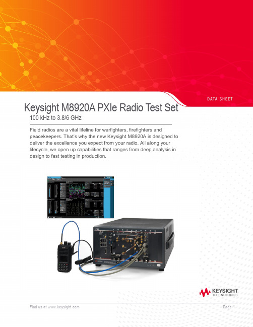
Keysight M8920A PXIe Radio Test Set 100 kHz to 3.8/6 GHzField radios are a vital lifeline for warfighters, firefighters andpeacekeepers. That’s why the new Keysight M8920A is designed to deliver the excellence you expect from your radio. All along your lifecycle, we open up capabilities that ranges from deep analysis in design to fast testing in production.Table of ContentsAccelerate MilCom and public safety radio manufacturing (3)Applications (3)Technical Specifications (4)Definitions and conditions (4)RF Analyzer Technical Specifications and Characteristics (5)RF Analyzer Technical Specifications and Characteristics (Continued) (6)RF Generator Technical Specifications and Characteristics (7)RF Generator Technical Specifications and Characteristics (Continued) (8)Audio Module Technical Specifications and Characteristics (8)Audio Module RX Audio Filters (9)Radio Test Application Specifications (9)N9093EM0E basic analog demodulation measurement application key specifications (9)N9093EM1E basic digital demodulation measurement application key specifications (9)Connectivity Test Application Specifications (10)WLAN 802.11ac (10)LTE-FDD/TDD (10)Bluetooth (10)Front Panel M9470A RF Interface Module Connections (10)General Specifications (11)Related Literature (12)Additional Information (12)Accelerate MilCom and public safety radio manufacturingDigital 2-way radios being developed for MilCom and the public safety radio market bring new testing challenges and hurdles to overcome for manufacturers and depot testing. Radio technologies are requiring wider bandwidths, higher frequencies, and multiple radio format capabilities.Product descriptionKeysight’s M8920A PXIe Radio Test Set supports many formats by combining PXI hardware with application-specific software in a single flexible and scalable chassis, providing broad multi-format coverage for next-generation radio testing.With Keysight’s new Radio Test Measurement Application (N9093), you can access and control multiple instruments on one screen while viewing a variety of critical measurements at the same time. Keysight can help deliver the operational excellence you expect from your radio.Applications−Cover all necessary analog AM and FM modulation test requirements.−Test APCO P1/P2, TETRA1, DMR, dPMR, ARIB, and custom modulation formats.−Test commercial connectivity formats including WLAN, LTE, Bluetooth®, etc.−All measurements can be performed with one click of a button.−Test analog Avionics Radios, and your Avionics Databus with optional Databus modulesM8920A PXIe Radio Test SetTechnical SpecificationsDefinitions and conditionsSpecifications describe the warranted performance of calibrated instruments. Data represented in this document are specifications under the following conditions unless otherwise noted.−Specifications are valid from 40° to 65 °C for individual module temperature, as reported by the module, and 20° to 35 °C for environment temperature unless otherwise noted −Calibrated instrument has been stored for a minimum of 2 hours within the allowed operating range−If instrument has previously been stored at a temperature range inside the allowed storage range, but outside the allowed operating range, instrument must have been stored for a minimum of 2hours within the allowed operating range before turn-on−30-minute warm-up time−Calibration cycle maintained−The RF, IF, and Source Alignments have been run within the previous 7 days−An ALL Alignment has been run within the previous 8 hours−If the temperature has changed more than 5 °C from the previous ALL AlignmentTypical describes additional product performance information that is not covered by the product warranty. It is performance beyond specifications that 80% of the units exhibit with a 95% confidence level. This data, shown in italics, does not include measurement uncertainty, and is valid only at room temperature (approximately 25 °C) after alignment within the stated alignment time and temperature limits.Nominal values indicate expected performance or describe product performance that is useful in the application of the product but are not covered by the product warranty.Recommended best practices in use−Use slot blockers and EMC filler panels in empty module slots to ensure proper operating temperatures. Keysight chassis and slot blockers optimize module temperature performance and reliability of test.−Set chassis fan to high at environmental temperatures above 45 °C.RF Analyzer Technical Specifications and Characteristics1.Instantaneous b andwidth (1 d B b andwidth) a vailable a round a c enter frequency o ver w hich t he i nput s ignal c an b e d igitized f or further a nalysis o rprocessing in the time, frequency or modulation domain.2.Calibration a ccuracy d epends o n h ow a ccurately t he f requency s tandard w as a djusted t o 10 M Hz. I f t he a djustment p rocedure i s f ollowed, t he c alibration accuracyis given by the specification. Achievable Initial Calibration Accuracy.3.The 3-dB cutoff frequency can be selected for the User-defined audio filters.RF Analyzer Technical Specifications and Characteristics (Continued)1.T/R port high power attenuation OFF2.Except at 100 MHz, 5 GHz, and 5.5 GHzRF Generator Technical Specifications and Characteristics1.Calibration a ccuracy d epends o n h ow a ccurately t he f requency s tandard w as a djusted t o 10 M Hz. I f t he a djustment p rocedure i s f ollowed, t he c alibrationa ccuracy is given by the specification. Achievable Initial Calibration Accuracy.2. Specifications apply when input port is set to Antenna InRF Generator Technical Specifications and Characteristics (Continued)Audio Module Technical Specifications and CharacteristicsAudio Module RX Audio FiltersRadio Test Application SpecificationsN9093EM0E basic analog demodulation measurement application key specificationsN9093EM1E basic digital demodulation measurement application key specifications1. The 3 dB cutoff frequency can be selected for the User-defined audio filters.Connectivity Test Application SpecificationsWLAN 802.11acLTE-FDD/TDDBluetoothFront Panel M9470A RF Interface Module ConnectionsGeneral SpecificationsFind us at Page 11PPFind us at Page 12Learn more at: For more information on Keysight Technologies’ products, applications or services , please contact your local Keysight office. The complete list is available at: /find/contactusThis information is subject to change without notice. © Keysight Technologies, 2018, Published in USA, Month July 11, 2019, 5992-2802ENRelated LiteratureFor more detailed product and specification information refer to the following literature and web pages: Publication titlePublication number M8920A PXIe Radio Test Set Technical Overview 5992-2821EN M8920A PXIe Radio Test Set Configuration Guide 5992-2800EN M8920A PXIe Radio Test Set Getting Started Guide M8920-90001 M9470A PXIe 50W Interface Module Data Sheet 5992-3140EN M9421A VXT PXIe Vector Transceiver Data Sheet 5992-1646EN M9260A PXIe Audio Analyzer Data Sheet 5992-1918EN PXIe Chassis Spec GuideM9019-90015 PC Tested Configurations with PXIe Chassis Technical Overview 5990-7632EN M9037A PXIe Embedded Controller Spec Guide M9037-90015 Interface Modules and Adapters for PXIe Systems5992-0377EN M924XA InfiniiVision PXIe Modular Oscilloscopes Data Sheet 5992-2003EN 6.5 Digit PXI Digital Multimeter Data Sheet 5992-2757EN PXIe Vector Network Analyzer Configuration Guide 5991-4885EN PXI Avionics Bus Interface Cards Configuration Guide 5992-2448EN 89600 VSA Software Configuration Guide5990-6386ENAdditional InformationProduct webpages:/find/M8920A /find/N9093 /find/PXIX-Series measurement applications: /find/X-Series_AppsSignal Studio Software:/find/signalstudio89600 VSA Software:/find/89600Bluetooth and the Bluetooth logos are trademarks owned byBluetooth SIG, Inc., U.S.A. and licensed to Keysight Technologies, Inc。
Keysight PXI GSM EDGE 测量套件数据手册说明书
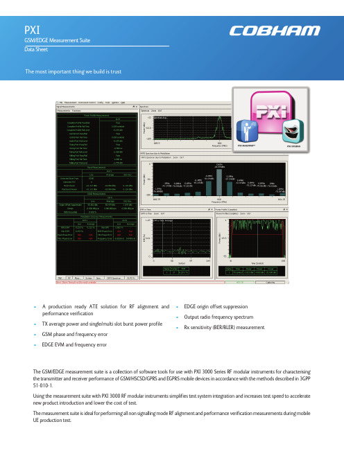
• A product i on ready ATE solut i on for RF al i gnment and performance verification•TX average power and single/multi slot burst power profile•GSM phase and frequency error •EDGE EVM and frequency error•EDGE origin offset suppression •Output radio frequency spectrum •Rx sensitivity (BER/BLER) measurementThe GSM/EDGE measurement suite is a collection of software tools for use with PXI 3000 Series RF modular instruments for characterising the transmitter and receiver performance of GSM/HSCSD/GPRS and EGPRS mobile devices in accordance with the methods described in 3GPP 51-010-1.Using the measurement suite with PXI 3000 RF modular instruments simplifies test system integration and increases test speed to accelerate new product introduction and lower the cost of test.The measurement suite is ideal for performing all non signalling mode RF alignment and performance verification measurements during mobile UE production test.The measurement suite components can be used for applications spanning bench-top manual operation in R&D to high volume production ATE.•Measurement and analysis component libraries provide programming APIs for highly customised ATE system integration for design validation or production.•An easy to use and versatile graphical user interface enables bench-top manual operation using PXI Studio 2 for design integration or trouble shooting•A test sequencer provides an out of the box production ready ATE solution using PXI Maestro software.The test sequencing feature provides an off the shelf production ready ATE solution for testing up to four devices in parallel. This includes fully integrated tester and device control providing the user the ability to write and execute a custom test sequence optimized for speed with ease.The test sequencing feature is an optional extension to the measurement suite used with PXI Maestro software.Manual operation uses PXI Studio 2 application software. This intuitive software, common to all measurement suites, allows the user to configure instrument and measurement parameters, execute measurements and display results.Measurements can be performed for either single or multiple active-slot GSM frames. Burst detection and signal analysis is performed on either Normal or Access burst types with automatic detection of modulation type from GMSK or 8PSK and automatic detection of training sequence (TSC). Measurement results are output as either numerical values with/without statistics or graphical trace displays.Signal generation waveforms provide downlink broadcast, control and data channels to simulate a BTS. These signals enable the mobile device to synchronise and perform receiver sensitivity measurements either as a single BER/BLER measurement or using loopback methods as defined in ETSI TS 100 293-GSM 04.14PXI Maestro and PXI Studi o 2 appli cati on software i s suppli ed free of charge wi th all PXI 3000 modules. Operati on of the GSM/EDGE measurement suite requires simple activation of a license key option on the PXI 3000 hardware. Further information for these applications is available through the following links:PXI StudioPXI MaestroSPECIFICATIONGSM/EDGEAll specifications are defined when used in conjunction with the 3030 Series PXI RF digitizer with option 100 operating in any GSM band between 400 MHz and 2000 MHz.Test sequencing with PXI Maestro additionally requires option 200Specifications are defined with the input signal at the RF digitizer tuned frequency and at the reference level unless otherwise stated. Measurements performed are in accordance with 3GPP TS 151 010-1 section 13 and 14 as applicable.BER/BLER measurements, Burst Timing Error measurements, specific timeslot analysis and multi-DUT operation additionally require a 3020 Series PXI digital RF signal generator to be assigned.CONFIGURATIONFrequencyUplink (Hz)User defined frequency or preset bands, as shown in the table belowBurst TypeGMSK: Auto or Manual (Normal / Access)8PSK: NormalTSC (training sequence)Uplink: Auto or Manual (0 to 7)Path Loss CorrectionTx and Rx (dB)Acquisition Trigger SourceImmediate (free run), Burst (video), Ext (PXI trigger bus, local bus, star trigger, LVDS, TTL)Synchronization (Auto Burst Detection)Burst Detection threshold (dB)Search length (ms)Burst Timing Latency Compensation0 to ±78.125 symbolsBER/BLER LoopbackGSM (Mode A/B)Number of Speech Frames: 1 to 250GSM (Mode C)Number of Burst Frames: 1 to 1000Measurement ResultsUseful Part/Guard (Pass / Fail)Useful Part/Guard Fail time (symbols)Useful Part/Guard Fail level (dB)Values with closest proximity to mask or worst case failure for the complete, rising edge, falling edge, guard and useful parts of the burst. Dynamic RangeTypically -80 dBc (for 3030 Series RF input levels > 0 dBm)Accuracy (rising falling edges)Level: Typically ±0.1 dB /10 dB(1)(relative to peak power)Time accuracy <0.5 μsAccuracy (useful part)Level: Typically ±0.02 dB (relative to peak power)Time accuracy <0.25 symbolAccuracy (Guard)Level: Typically ±0.1 dB /10 dB(1)(relative to peak power)Time Accuracy <0.25 symbolGMSK MODULATIONGMSK phase error measurements performed for a single slotPhase Error Range0 to 100RMS0 to 400peakIndicationResults are expressed as numerical values for RMS + Peak phase errorTracesPeak phase error vs. timeAccuracyBetter than ±0.5° rms phase error ±1.0° peak phase error8PSK MODULATIONThe minimum RMS magnitude of the error vector is calculated for a single slot.Burst TypeNormal onlyEVM Range0 to 20% EVM RMS0 to 40% EVM peakIndicationEVM % (rms and peak), phase error degrees (rms and peak), 95th percentile EVM %, origin offset suppression (dB), and droop (dB) Accuracy±0.4% RMS ±1% peakOffset Origin Suppression Range>20 dB to 60 dB (floor)Offset Origin Suppression Accuracy±0.5 dB at 33 dBNotes(1) Excluding the effects of noise(2) Requires opt 100BLERMeasurement ResultsBlock Error Rate (%)Number of Radio Blocks TestedNumber of Radio Blocks in ErrorNumber of Active Slots Analyzed per frameBER, BER II, RBER II, FERMeasurement ResultsMode C burst loopbackNumber of bits examinedNumber of error bits foundBit Error Rate (%)Mode A/B Speech loopbackNumber of frames examinedErased Speech FramesSpeech Frame Erasure Rate (%)GENERALOperating SystemWindows®7/32-bit or 7/64 bitRequired Memory512 Mbytes minimum, 1024 Mbytes recommendedDisplay ResolutionMinimum 1024 x 768OtherPXI 3000 Series modules require NI VISA version 4.6 or later (NI Visa 4.2 or later). PXI 3000 Series module drivers version 7.0.0 or laterORDERINGGSM/EDGE Measurement SuiteWhen purchased with a 303x, order as: 3030 option 100When purchased as an upgrade, then order as: RTROPT100/3030GSM/EDGE test sequencing (for use with PXI Maestro)(2)When purchased with a 303x, order as: 3030 option 200When purchased as an upgrade, then order as: RTROPT200/3030PXI Studi o 2 and PXI Maestro core appli cati ons are suppli ed as standard wi th PXI 3000 Seri es modules or may be downloaded from/products/validation/modular-instrumentation/pxi/application-software/Cobham Wireless -Validation/wireless Part No.46891/475, Issue 5, 07/15。
规格大翻新 是德模组化测试方案重装上阵

规格大翻新是德模组化测试方案重装上阵
是德科技(Keysight Technologies)发布新款向量网路分析仪(VNA)、可编程步进衰减器、讯号分析仪(SA)、任意波形产生器(AWG)及参考解决方案等五大PXI、AXIe架构模组化测试产品,并大幅提升规格和功能,主要将瞄准类比、数位、射频、微波及光波测试等应用领域。
台湾是德科技董事长暨总经理张志铭表示,凭藉着过去深耕射频领域的核心技术和创新竞争力,以及坚强且多元的产品阵容,该公司在PXI模组化测试仪器的市占已从2010年不到5%,成长至2013年的13%;未来将持续厚实产品线的完整性,同时增添突破性的规格与功能,进一步扩大市占。
台湾是德科技董事长暨总经理张志铭(右2)表示,随着产品不断推陈出新,该公司已拥有更多元且完备的模组化测试解决方案,可满足客户现今和未来的需求。
右1为行销处副总经理罗大钧,左起为元件测试部市场发展经理Steven Huang、数位测试业务部大中华区市场经理杜吉伟、亚太区市场开发经理梁雄伟、软体与模组方案部方案经理Sheri DeTomasi。
PXI和AXIe模块化解决方案
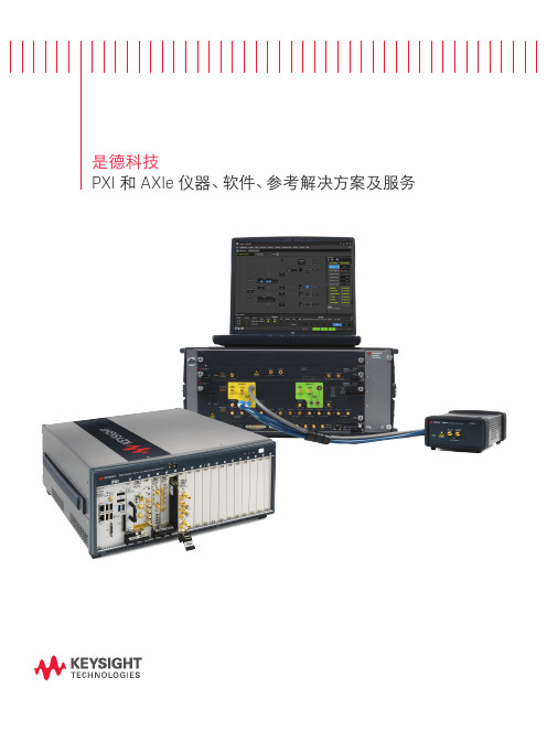
是德科技PXI 和 AXIe 仪器、软件、参考解决方案及服务是德科技模块化解决方案无与伦比的性能。
加速测量洞察。
开启测量新视野是德科技传承 75 年创新史,始终致力于为用户开启全新的测量视野。
秉承这一理念一路走来,我们创造了业界领先的测试测量设备,总有适合的产品能够满足您的需求:全尺寸的台式仪器、小型台式仪器、手持式仪表或模块化仪器。
我们的目标是提供全面的全球测试解决方案 - 硬件、软件、全球支持和应用专业技术,为您的团队提供所需的知识和技能,使其保持行业领先优势。
在模块化仪器领域,我们的硬件创新主要集中在两个特定的领域:PXI 和 AXIe 。
我们将无与伦比的测量性能和始终一致的测量技术融入 PXI 和 AXIe 系列射频、微波和高速数字仪器中。
为了帮助您更快开始构建测试系统,我们记录了许多针对特定应用领域(从功率放大器测试到卫星信号监测)的参考解决方案供您借鉴。
软件是所有测试系统都不可或缺的组成部分 ― 是德科技软件将我们渊博的专业技术集于一身,供您下载使用。
我们为您的团队提供卓越的工具,帮助您加速将数据转化为信息,进而转化为可以指导实践的洞察力。
我们还提供软件面板控制和基本的实用程序,从而使我们的模块化产品开箱后几分钟内即可投入使用,确保您快速开始首次测量。
是德科技拥有业界非常庞大的应用工程师团队 ― 他们遍布全球各地,而且在射频、微波和数字等领域积累了极其丰富的技术经验,在业界长期保持领先优势。
是德科技的全球三年标准保修是我们对卓越产品质量的承诺。
我们的多厂商一站式校准和正常运行时间服务,确保您的仪器具有持续的精度、性能和可用性。
我们能以快达四小时的响应时间,创建定制的服务计划。
我们在全球拥有超过 50 个服务地点的服务网络和移动校准团队,可以提供更大的便利和灵活性,保持您的产品和测试系统以保证的技术指标运行。
是德科技的模块化解决方案通过提供无与伦比的 PXI 和 AXIe 性能,帮助您应对射频、微波和数字领域最苛刻的技术挑战。
是德科技推出10款PXIe仪器,为5G、航空航天和国防以及量子技术研究保驾护航

是德科技推出10款PXIe仪器,为5G、航空航天和国防以及
量子技术研究保驾护航
佚名
【期刊名称】《国外电子测量技术》
【年(卷),期】2017(36)2
【摘要】是德科技公司(NYSE:KEYS)发布了十款新PXIe仪器,包括任意波形发生器(AWG)和全能型PXI示波器。
新款任意波形发生器具有三个高度同步的通道,可以精确调谐IQ波形并进行包络追踪。
任意波形发生器和示波器均具有高达1GHz的带宽,能够轻松胜任复杂的基带IQ信号生成和分析,可用于评测新兴的5G和航空航天及国防宽带技术。
【总页数】1页(P109-109)
【关键词】航空航天;宽带技术;任意波形发生器;仪器;科技;国防;护航;量子
【正文语种】中文
【中图分类】TP393.4
【相关文献】
1.是德科技推出新款PXI Express SMU高速源/测量单元是德科技PXIe产品线的新成员将加速射频功率放大器的生产测试 [J],
2.是德科技推出10款PXIe仪器,为5G、航空航天和国防以及量子技术研究保驾护航 [J],
3.是德科技推出新款PXI Express SMU高速源/测量单元是德科技PXIe产品线的新成员将加速射频功率放大器的生产测试 [J],
4.10款PXIe仪器为5G、航空航天和国防应用保驾护航 [J],
5.是德科技推出10款PXIe仪器,为5G、航空航天和国防以及量子技术研究保驾护航 [J],
因版权原因,仅展示原文概要,查看原文内容请购买。
PXI 多路复用器开关模块 (M9101A、M9102A、M9103A)
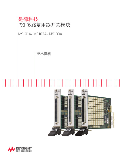
1x10⁹ > 5x10⁶
1. 并非用于连接至电源(Mains)。 2. 继电器使用寿命在路径电阻小于 1.5 Ω 情况下确定。
图 2. M9101A 64 通道、双线、簧片式继电器
图 3. 200 LFH 连接器模块
06 | 是德科技 | PXI 多路复用器开关模块 M9101A、M9102A、M9103A —— 技术资料
开关转换速度 最大电压 (典型值) (典型值) 1000 µsec1 100 Vrms2
1000 µsec1 100 Vrms2
4.5 msec1
100 Vrms2
电流开关/负载 继电器 (典型值) 类型 0.5 A/1.0 A 簧片式
0.5 A/1.0 A 簧片式
1.0 A/1.0 A 电枢
连接器
通道 1 通道 2
通道 3
共享 图 4. M9102A 128 通道、单线、簧片式继电器
通道 128
M9102A 技术指标和特征
一般技术指标
通道数
128
开关类型
高密度,单线簧片式
最大电压1
100 Vrms
最大电流开关/负载
0.5 A/1.0 A
切换特征,标称值
最大功率 开关转换速度(典型值) 初始路径电阻,单端(典型值)
另外还包括适用于 LabView、LabWindows/CVI、Visual Studio、 C、C++、C#、Visual Basic 和 MATLAB 的应用程序编码实例。它 们提供了开关设置和基本的开关功能。编码示例便于修改,因此 能将开关模块快速整合到测量系统中。
基于PXI的高速数字化仪模块

基于PXI的高速数字化仪模块PXI 总线是NI 公司在计算机外设总线PCI 的基础上实现的新一代仪器总线,已经成为业界开放式总线的标准,基于PXI 总线的数字化仪模块是现代测试系统中重要的一种数据记录与处理设备。
设计一个双通道12 bit/250 MHz 采样频率的高速数字化仪模块,以高性能FPGA 器件为核心,实现对高速A/D 的控制以及高速数据处理和存储,解决了长时间高速记录信号的测试难题。
1 系统工作原理数字化仪模块主要由前端信号调理通路、模数转换电路、数据存储单元、数据采集控制电路、PXI 接口电路等部分组成,其原理框图如图l 所示。
高速模拟信号首先经过信号调理通路进行放大、衰减等处理,将幅度调整到A/D 转换器允许输入的电压范围内,并转化成LVDS 格式的差分信号,然后送到A/D 转换器;FPGA 芯片接收A/D 输出的高速数据流,经过降速、抽取滤波等处理后,存储到数据存储单元SRAM 中,并发出中断信号,PXI 主机响应中断后经由FPGA 将存储在SRAM 中的数据读入主机内存,完成后续的数据处理和显示。
PXI 主机通过PXI 总线发送控制命令,经FPGA 译码后实现对数据采集和调理通路控制。
该数字化仪模块为每个通道预留了4Mb 的存储容量,当组成PXI 测试系统时,可以将数据写入计算机硬盘,实现更长时间的记录。
两个通道可以独立工作,也可以相互关联。
采集方式可以有内触发、外触发、软件触发、通道触发等多种模式。
2 系统设计实现2.1 模块化的FPGA 设计本文所设计的数字化仪是基于高性能FPGA 芯片实现的,FPGA 承担了绝大部分的控制和数据处理任务,是本设计的核心器件。
对FPGA 进行模块化设计,是大型系统设计的常用方法。
合理分割功能模块,能加快FPGA 的开发,。
AXIe 高速数字化仪(M9710A)
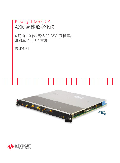
比以往更深入和敏锐的洞察引言M9710A 是一款 10 位 AXIe 高速数字化仪,具有 4 个同步通道,以及高达 10 GS/s 的采样率和 2.5 GHz 带宽,因此成为尖端物理实验和航空航天与国防领域中多通道应用的理想选择。
产品描述M9710A 是一款独特的单插槽 10 位高速数字化仪,能够以 5 GS/s 或 10 GS/s 的采样率捕获直流至 2.5 GHz 的信号。
它在单一插卡中的 4 个相位相干通道上提供优异的测量精度和高动态范围。
优化响应支持几百皮秒的脉冲分析。
交织采样选件可使两个 5 GS/s 通道合并起来,在 2 个通道上提供 10 GS/s 的采样率,以保证出色的测量保真度。
M9710A 高速 DAQ 还提供了高达 8 GB 的深采集存储器,并配有Virtex-6 FPGA 提供实时数据处理能力。
M9710A 高速数字化仪还可以与是德科技 89600 VSA 软件和AcqirisMAQS 软件结合使用,以实施先进的多通道信号分析。
如欲了解其他固化软件选件的信息,请与是德科技联系:digitizers@应用–先进科研实验–流体力学实验–多通道实验产品特性–2 通道在 10 位分辨率下,采样率高达 10 GS/s(启用交织采样模式)–4 通道在 10 位分辨率下,每通道同时采样率高达 5 GS/s–直流至 2.5 GHz 带宽–50 Ω输入阻抗,直流耦合–可选择 250 mV 或 1 V 满量程(FSR)–15 ps RMS 触发时间插补器(TTI)精度–低噪声密度和低失真–优化频率响应平坦度–板上存储器高达 8 GB DDR3(1.6 MSa/通道)–PCI Express 2.0 四通道(x4)背板支持高达 1.4 GB/s 持续数据吞吐量为客户提供高价值产品–快速 AXIe 10 位数字化仪–捕获宽带宽信号–宽动态范围采集可提高测量保真度–精确的测量–大容量板上存储器–很高的数字化数据吞吐量–软件支持包括多个可编程接口,可以与现有环境轻松集成–缩短开发时间,加快上市速度硬件平台产品概述M9710A 是一款模块化 AXIe 10 位数字化仪,其特性可根据应用要求进行扩展。
安捷伦将测试产品推向模块化
安捷伦将测试产品推向模块化
近日,安捷伦科技在在深圳举办了亚洲区最大的测试测量科技盛会全方位展现了安捷伦电子测试测量的魅力。
模块化测试设备
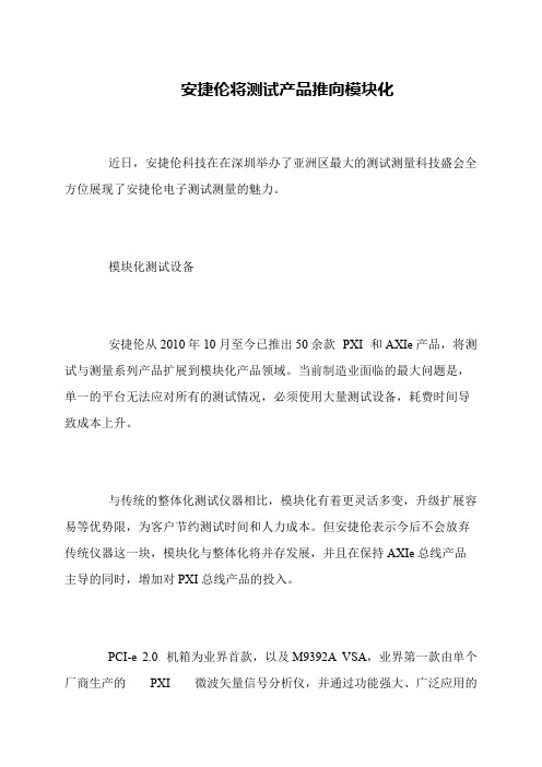
安捷伦从2010年10月至今已推出50余款PXI 和AXIe产品,将测试与测量系列产品扩展到模块化产品领域。
当前制造业面临的最大问题是,单一的平台无法应对所有的测试情况,必须使用大量测试设备,耗费时间导致成本上升。
与传统的整体化测试仪器相比,模块化有着更灵活多变,升级扩展容易等优势限,为客户节约测试时间和人力成本。
但安捷伦表示今后不会放弃传统仪器这一块,模块化与整体化将并存发展,并且在保持AXIe总线产品主导的同时,增加对PXI总线产品的投入。
PCI-e 2.0 机箱为业界首款,以及M9392A VSA,业界第一款由单个厂商生产的PXI 微波矢量信号分析仪,并通过功能强大、广泛应用的。
AXIe和PXI引领模块化测试潮流

AXIe和PXI引领模块化测试潮流
佚名
【期刊名称】《今日电子》
【年(卷),期】2010(0)11
【摘要】AXle是基于AdvancedTGA的标准.可扩展至仪器和测试领域。
AXle 联盟(www.axiestandard ,org)的目标是提供一个开放式标准,
【总页数】1页(P50-50)
【关键词】测试;模块化;PXI;潮流;可扩展;开放式;标准
【正文语种】中文
【中图分类】TP216
【相关文献】
1.安捷伦将先进的模块化测量技术引入PXI和AXIe领域 [J], 从秋波
2.是德科技扩充PXI、AXIe仪器和参考解决方案阵容,同时推出跨厂商校准服务全面性的服务协助工程师以更低成本开发、部署和维护测试系统 [J],
3.NI成功主办第七届“中国PXI技术和应用论坛”——构建以软件为核心的模块化测试系统架构,展望2010自动化测试发展趋势 [J],
4.NI举办第十三届"PXI技术和应用论坛",引领PXI发展新潮流 [J],
5.NI举办第十三届“PXI技术和应用论坛”,引领PXI发展新潮流 [J],
因版权原因,仅展示原文概要,查看原文内容请购买。
PXI规范——仪用PCI的扩充(版本1.0)

PXI规范——仪用PCI的扩充(版本1.0)
范东华
【期刊名称】《电子测试》
【年(卷),期】1998(011)005
【摘要】1.前言本节阐述PXI(仪用PCI扩充)规范的主要目的和基本内容。
它也定义了预期的用户并列出相关的术语和文件。
1.1. 目的 PXI是应广大仪器仪表与自动化领域用户的要求编制的,以期从易于集成和使用的小型系统获得与日俱增的性能、功能与可靠性。
【总页数】5页(P37-41)
【作者】范东华
【作者单位】无
【正文语种】中文
【中图分类】TP317
【相关文献】
1.PXI规范——仪用PCI的扩充(版本1.0)(中) [J],
2.PXI规范—仪用PCI的扩充(版本1.0)(下) [J], 范东华
3.凌华科技推出高分辨率PCI规格的数字化仪系列产品PCI-9816、PCI-9826以及PCI-9846——凌华科技积极扩充高分辨率数字化仪产品线,PCI-9816/9826/9846系列提供高精度、低噪音及高动态范围性能 [J], 无
4.阿尔泰推出高速高精度PXI/PCI-85XX系列数字化仪 [J],
5.PCI接口的高动态范围的数字化仪基于PC的示波器提供PCI和PXI接口的通用仪器功能 [J],
因版权原因,仅展示原文概要,查看原文内容请购买。
- 1、下载文档前请自行甄别文档内容的完整性,平台不提供额外的编辑、内容补充、找答案等附加服务。
- 2、"仅部分预览"的文档,不可在线预览部分如存在完整性等问题,可反馈申请退款(可完整预览的文档不适用该条件!)。
- 3、如文档侵犯您的权益,请联系客服反馈,我们会尽快为您处理(人工客服工作时间:9:00-18:30)。
创造更高价值
更佳的测量保真度和信号完 整性
– 显示更深入和更清晰的结果 – 可重复性
更高测量吞吐量
– 快速侦测和决策 – 工作效率
● ● ●
更小体积
– 专门设计用于尺寸和功率优化 – 高信道密度
♦ ♦ ♦ ♦ ♦ ♦ 作性 可重复使用且可升级 非常高的可靠性 支持和维护
如欲获得是德科技的产品、应用和服务信息,请 与是德科技联系。如欲获得完整的产品列表,请 访问: /find/contactus 是德科技客户服务热线 电子邮件: tm_asia@ 是德科技 (中国) 有限公司 北京市朝阳区望京北路 3 号是德科技大厦 邮编: 100102 是德科技 (成都)有限公司 成都市高新区南部园区天府四街 116 号 邮编: 610041 是德科技香港有限公司 香港北角电器道 169 号康宏汇 25 楼 上海分公司 上海市虹口区四川北路 1350 号 利通广场 19 楼 邮编: 200080 深圳分公司 深圳市福田区福华一路 6 号 免税商务大厦裙楼东 3 层 3B-8 单元 邮编: 518048
M9203A PXIe 12 位高速数字化仪 / 宽带数位接收机 1 - 2 通道 3.2 GS/s (1 通道 ), 1.6 GS/s (2 通道 ) 12 位 直流至 2 GHz 4 GB (1 GSa/ 通道) Xillinx FPGA 双量程, 1V和2V 50 Ω PCIe, 2 插槽, 全屏蔽, 内置散热系统 包括 Windows, Linux
M9703B AXIe 12 位高速数字化仪 / 宽带数位接收机 4 - 8 通道 3.2 GS/s (4 通道) 1.6 GS/s (8 通道) 12 位 直流至 2 GHz 16 GB (1 GSa/ 通道) Xillinx FPGAs (4x) 双路, 1V和2V 50 Ω AXIe, 1 插槽, 全屏蔽, 内置散热系统 包括 Windows, Linux
myKeysight /find/mykeysight 个性化视图为您提供最适合自己的信息 ! AdvancedTCA® Extensions for Instrumentation and Test(AXIe) 是基于 AdvancedTCA 标准的一种开放标准 , 将 AdvancedTCA 标准扩展到通用测试半 导体测试领域。是德科技是 AXIe 联盟的创始成员。 PCI 扩展仪器 (PXI) 模块化仪器提供坚固耐用、基于 PC 的高性能测量与自动化 系统。 3 年保修 是德科技卓越的产品可靠性和广泛的 3 年保修服务完美结合,从另一途径帮 助您实现业务目标: 增强测量信心、降低拥有成本、增强操作方便性。
图 3. 八台 M9703B AXIe 12 位数字化仪安装在 M9514A 14 插 槽 AXIe 机箱中, 组成 64 信道 12 位采集系统。 了解可能的配 置, 请联系厂家。
7 | 是德科技 | 高速数字化仪——选型指南
如欲获得是德科技的产品、应用和服务信息,请与是德科技联系。如欲获得完整的产品列表,请访问: /find/contactus
广州分公司 广州市天河区黄埔大道西 76 号 富力盈隆广场 1307 室 邮编: 510623 西安办事处 西安市碑林区南关正街 88 号长 安国际大厦 D 座 501 邮编: 710068 南京办事处 南京市鼓楼区汉中路 2 号 金陵饭店亚太商务楼 8 层 邮编: 210005 苏州办事处 苏州市工业园区苏华路一号世 纪金融大厦 1611 室 邮编: 215021 武汉办事处 武汉市武昌区中南路 99 号 武汉保利广场 18 楼 A 座 邮编: 430071 上海MSD办事处 上海市虹口区欧阳路 196 号26 号楼一楼 J+H 单元 邮编: 200083
●
最新
● ● ●
最新 最新 最新
♦ ♦ ♦ ♦ ♦ ♦ ♦
多达 16 信道, 12 位系统 多达 40 信道, 12 位系统 多达 104 信道, 12 位系统
♦
多达 8 信道, 10 位系统 多达 20 信道, 10 位系统 多达 52 信道, 10 位系统
♦
多达 32 信道, 8 位系统 多达 96 信道, 8 位系统
是德科技 高速数字化仪
选型指南
是德科技高速数字化仪专业技术
创造更高价值
借助 PXIe 和 AXIe 高速数字化仪, 是德科技可以与您建立可靠的合作伙伴关系, 助您完成 先进产品的开发工作。 是德科技独有的技术使用专有的集成电路, 使您可以充分利用数字化仪中集成的模 拟数字转换器 (ADC) 和现场可程序设计门阵列 (FPGA) 。 FPGA 中的板上实 时算法支持快速检测不同域中的信号特征。 我们提供了范围广泛的韧体和应用软件选件: – 韧体选件: 特定实时功能能够缩短您的整体系统响应 时间, 例如平均器或数字下变频。 – 应用软件选件: 捆绑套件包括用于特定配置的软件和固化 软件, 以满足其特定需求, 例如数据流传输和记录。 此外, 如果您需要集成您自己的自定义实时 IP 算法, 那么您还需要额外的软 件套件, 即我们提供的 FPGA 开发工具包。 是德科技高速数字化仪插卡可以作为多种应用的组件, 例如: – 航空航天与国防: 雷达和卫星 – 物理: 高级和多通道实验 – 射频通信: 5G、 宽带、 MIMO 无论您是已经明确了应用需求, 还是处在选型的初期, 我们的数字化仪专家都能够帮助您 确定理想的解决方案, 充分满足您的应用需求。
更佳的测量保真度和信号完 整性
– 显示更深入和更清晰的结果 – 可重复性
更高测量吞吐量
– 快速侦测和决策 – 工作效率
更小体积
– 专门设计用于尺寸和功率优化 – 高信道密度
降低总体拥有成本
– – – – 互操作性 可重复使用且可升级 非常高的可靠性 支持和维护
3 | 是德科技 | 高速数字化仪——选型指南
PXIe 高速数字化仪
最新
主要技术指标 产品 通道数 最大采样率 ADC 分辨率 最大带宽 最大存储深度 FPGA 信号处理 满量程 (FSR) 输入阻抗 外形 软件前面板 (SFP) 和驱动程序 操作系统 固化软件选件 -DGT -INT -FDK -DDC -TSR 应用软件选件 -CB0 -CB2 -BB1 相关软件 U5340A U1092A-S0x W1462BP 89601B 相关产品 M9019A M9021A M9048A M9036A M9037A M9393A M9362AD01 PXIe 18 插槽机箱, 3U, 24 GB/s PXIe 至 PCIe 电缆接口 PCIe 台式适配器 PXIe 嵌入式控制器 PXIe 高性能嵌入式控制器 PXIe 高性能向量信号分析仪, 50 GHz PXIe 四路下变频器, 10 MHz 至 50 GHz 用于高速数字化仪的 FPGA 开发工具包 AcqirisMAQS 多信道采集软件 SystemVue FPGA 架构 89600 VSA 软件, 可转移许可证 数字化仪数据流和记录 数字下变频器数据流速率为 1.6 GS/s 高保真数字化仪 数字化仪固化软件 信道交织采样功能 定制固化软件功能 宽带实时数位下变频器 触发同时采集和读出
配置实例
图 1. 两台 M9703B AXIe 12 位数字化仪安装在 M9505A 5 插槽 AXIe 机 箱中, 组成 16 信道 12 位采集系统。
图 2. 五台 M9703B AXIe 12 位数字化仪安装在 M9505A 5 插槽 AXIe 机 箱中, 组成 40 信道 12 位采集系统。
/find/m9703B /find/m9710A /find/m9709A /find/m9203A
本文中的产品指标和说明可不经通知而更改
© Keysight Technologies, 2017 Published in USA, August 6, 2017 出版号:5992-1974CHCN
4 | 是德科技 | 高速数字化仪——选型指南
AXIe 高速数字化仪
最新
主要技术指标 产品 通道数 最大采样率 ADC 分辨率 最大带宽 最大存储深度 FPGA 信号处理 满量程 (FSR) 输入阻抗 外形 软件前面板 (SFP) 和驱动程序 操作系统 固化软件选件 -DGT -INT -FDK -DDC -LDC -TSR 应用软件选件 -CB1 -CB2 -B01 相关软件 U5340A U1092A-S0x W1462BP 89601B 相关产品 M9502A M9505A M9514A M9537A 2 槽 AXIe 机箱 5 槽 AXIe 机箱 14 槽 AXIe 机箱 AXIe 高性能嵌入式控制器 用于高速数字化仪的 FPGA 开发工具包 AcqirisMAQS 多信道采集软件 SystemVue FPGA 架构 89600 VSA 软件 数字下变频器数据流速率为 1 GS/s 数字下变频器数据流速率为 1.6 GS/s 增强的信号处理能力 数字化仪固化软件 信道交织采样功能 定制固化软件功能 宽带实时数位下变频器 有限实时数字下变频固化软件 触发同时采集和读出
是德科技高速数字化仪所获奖项
构建多信道数据采集系统
只需在一台机箱中安装您选择的数字化仪, 就可以构建大型系统。 我们还提供一系列可配置的配套产品, 包括信号调理、 机箱和控制器。 AcqirisMAQS 多信道采集软件专为大型实验而设计, 可以通过独立的控制面板来完成配置 管理, 显示数百个信道上的数据。
定制实时处理
用于高速数字化仪的 U5340A + FDK 选件 FPGA 开发工具包
多通道采集
U1092A-S0x AcqirisMAQS
仅 Windows 系统 IO 链接库套件 包括在您的数字化仪中
软件要求额外许可证
6 | 是德科技 | 高速数字化仪——选型指南
高速多信道数据采集系统
Keysight AXIe 高速数字化仪为流体力学、 聚变等离子体、 粒子物理学、 航空航天和国防领 域中的先进实验提供了理想的解决方案。 使用这些模块, 您能够构建大量的同步采集通 道, 在很小空间内提供前所未有的测量保真度。 先进 IP 设计、 最新技术、 板上实时数据处 理能力相辅相成, 可实现卓越性能。
