CCNP实验拓扑图(全)
CCNP课程设计之酒店组网方案精品文档33页

课程设计报告2010 ~ 2011 学年第学期教学单位计算机工程系课程名称 CCNP课程设计题目酒店网络的规划指导教师梁艳学生姓名谭嘉胜专业名称计算机网络技术年级 09酒店网络的规划一.概况1.课程设计目的:向客户提供高速上网,提高酒店的服务档次,是为了寻求酒店经济的增长点,提高酒店的竞争力。
通过传播酒店的声音,发布酒店的信息,开放酒店面向客户的信息,提供查询酒店信息的渠道,建立网络信访机制,可加深酒店与客人的感情。
通过广泛开展对酒店客人提供公益性的信息服务,例如新闻报道、天气预报、旅游指南、航班信息、求医问药和列车时刻查询等,可建设酒店的信息化环境。
酒店可以在宽带网上运行酒店管理系统及酒店网站,向全社会推介酒店的业务。
可实现酒店内部资源共享,提高资源的利用率,为酒店节省开支。
可为酒店提供电子商务,扩大酒店的业务范围、促进酒店的管理模式的转变、提高酒店的工作效率。
可为酒店向自动化办公及无纸办公的发展提供条件。
2. 客户的具体需求:统计资料显示,酒店客户中45%的人有上网需求,并且其中有30%的客人提出了高速上网的要求。
值得注意的是,对上网速度有强烈需求的客户,对价格又不是很敏感,这些客人是各个酒店利润的主要来源,也是各大酒店竭力争取的商住客户或者常住客户。
因此,对于同等星级的酒店,在管理水平和房间设施趋于相近的情况下,提供高质量的互联网接入服务是酒店吸引更多商务客人入住的有效手段。
采用宽带接入可以显著提高星级酒店的信息化服务水平,酒店入住客人可以轻松自如地实现诸如网上冲浪、IP电话及可视电话、电视会议、电子商务、VOD点播(互动点播电视节目和电影)、虚拟专用网络(VPN)等功能。
二.设计原则1.网络需求分析酒店上网系统项目涉及到该酒店的3层楼,共计60个信息点,酒店为每个客房的接入带宽为100M。
酒店在二层设置1个管理间,所有的客房的信息点都进到酒店二层楼管理间,进行集中管理。
2.建设目标实现酒店内部每个房间上网的需求,提供高质量的互联网接入服务吸引更多商务客人入住。
几款网络模拟器软件在计算机网络实验课程中的应用

几款网络模拟器软件在计算机网络实验课程中的应用计算机网络实验课程是计算机网络专业最重要的实验课程,由于计算机网络实验涉及的内容比较多,受实验室条件的限制,在缺乏计算机网络实验硬件设备的条件下,如何开展计算机网络实验教学是值得研究的问题。
通过在计算机网络实验教学中的实践,发现可以借助几款网络模拟器软件建立模拟实验环境,开展计算机网络的实验教学,进行网络仿真实验。
网络模拟器是专业研究机构和公司开发的网络仿真工具软件,是为网络初学者设计的用于提供计算机网络设计、配置和网络故障排除模拟环境的学习平台,它支持用户进行仿真、虚拟和活动的网络模型。
网络模拟器能够模拟出各种网络硬件设备,使用者可以在单机环境下设计拓扑结构,组建网络进行仿真实验。
学生可以在网络模拟器的网络环境中,进行反复练习,不仅提高自己的实践动手能力和解决实际问题的能力,而且提高了计算机网络实验效率,降低实验成本。
同时,培养学生组建、维护和管理网络的能力,增强学生对计算机网络理论和概念的掌握和理解。
目前,网络模拟器种类繁多,一些网络设备公司都积极开发与之相配套的网络模拟软件,思科、华为、AT&T等网络设备供应商都相继推出网络模拟器。
广受网络、通信等专业的教学部门和培训机构青睐的网络模拟器主要有Boson NetSim>Packet Tracer>Dy namips等模拟软件,现就这几款网络模拟器软件在计算机网络实验中的应用进行分析。
一、Boson Netsim网络模拟器软件及应用实例Boson Netsim是Boso n公司开发的一一款网络模拟软件,它最先提出自定义网络拓扑的功能,大多数人都使用它来练习CCNA和CCNP的实验。
它由Bo son Network Designer (网络拓扑图设计)和Boson Netsim(实验模拟器)两部分组成。
Boson NetSim能够实现交换机基本实验、路由器基本实验、远程访问基本实验以及进阶实验。
VOLCANO 实验手册v1.0

西安.威克诺CCNA and CCNP实验手册v1.0Derek Liu2010-10-1网址:电话:400—715—8369E-mail:liupeng@ 此文档内容献给所有喜爱Cisco的人,有任何问题可以使用邮件和我交流,文档主要是CCNA和CCNP实验此版本目前只包含基础实验、静态路由实验以及RIP实验,实验手册会不断的进行更新,请关注最新版本(目前版本为V1.0)!目录实验手册 (3)基础实验 (3)一、制作平行线和交叉线: (3)二、路由器的基本配置: (4)三、连通性实验: (5)路由实验 (9)实验物理拓扑: (9)一、静态路由: (9)实验一:简单静态路由 (9)实验二:静态汇总路由 (12)实验三:静态缺省路由 (13)实验四:浮动路由 (14)实验五:负载均衡 (16)实验六:递归表查询 (18)二、动态路由: (20)1、Routing information Protocol (RIPv1 and RIPv2) (20)实验一:基本的RIP配置 (20)实验二:RIPv1不连续子网 (22)实验三:RIPv2、认证、被动接口 (24)实验四:RIPv2单播更新 (26)实验五:RIPv2水平分割 (28)实验六:Offset-list (31)实验七:RIP手动汇总 (33)实验八:RIP缺省路由 (35)实验手册基础实验一、制作平行线和交叉线:①平行线制作方法:平行线的制作线序,一头是568B 另一头也是568B(请看下图)从左向右数,橙白橙绿白蓝蓝白绿棕白棕。
②交叉线制作方法:交叉线的制作线序,一头是568A 另一头是568B(请看下图)二、路由器的基本配置:路由器模式详解:路由器基本命令详解:Router>enable //进入特权模式Router#disable //退出特权模式Router#configgure terminal //进入全局配置模式Router(config)#enable password [ 密码] //配置用户模式到特权模式的明文密码Router(config)#enable secret [ 密码] //配置用户模式到特权模式的密文密码Router(config)#service password-encryption //将路由器中所有明文的密码转为加密形式显示Router(config)#hostname [ 名字] //修改设备名称Router(config)#no ip domain-lookup //关闭命令域名解析Router(config)#banner motd $ [ text ] $ //修改login提示信息Router(config)#line console 0 //进入console 口配置模式Router(config-line)#password [ 密码] //配置使用console口管理设备的密码Router(config-line)#login //允许登陆,可以说将刚刚配置的密码生效。
CCNP实验大全--Snapshot_odr-
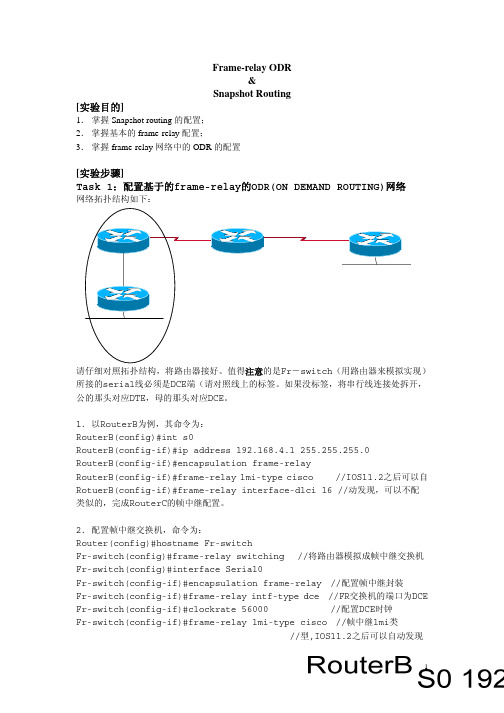
Frame-relay ODR&Snapshot Routing[实验目的]1.掌握Snapshot routing的配置;2.掌握基本的frame-relay配置;3.掌握frame-relay网络中的ODR的配置[实验步骤]Task 1:配置基于的frame-relay的ODR(ON DEMAND ROUTING)网络网络拓扑结构如下:请仔细对照拓扑结构,将路由器接好。
值得注意的是Fr-switch(用路由器来模拟实现)所接的serial线必须是DCE端(请对照线上的标签。
如果没标签,将串行线连接处拆开,公的那头对应DTE,母的那头对应DCE。
1.以RouterB为例,其命令为:RouterB(config)#int s0RouterB(config-if)#ip address 192.168.4.1 255.255.255.0RouterB(config-if)#encapsulation frame-relayRouterB(config-if)#frame-relay lmi-type cisco //IOS11.2之后可以自RotuerB(config-if)#frame-relay interface-dlci 16 //动发现,可以不配类似的,完成RouterC的帧中继配置。
2.配置帧中继交换机,命令为:Router(config)#hostname Fr-switchFr-switch(config)#frame-relay switching //将路由器模拟成帧中继交换机Fr-switch(config)#interface Serial0Fr-switch(config-if)#encapsulation frame-relay //配置帧中继封装Fr-switch(config-if)#frame-relay intf-type dce //FR交换机的端口为DCE Fr-switch(config-if)#clockrate 56000 //配置DCE时钟Fr-switch(config-if)#frame-relay lmi-type cisco //帧中继lmi类//型,IOS11.2之后可以自动发现Fr-switch(config-if)#frame-relay route 17 interface Serial1 16// 配置帧中继交换表Fr-switch(config-if)#exitFr-switch(config-if)#interface Serial1Fr-switch(config-if)#encapsulation frame-relayFr-switch(config-if)#frame-relay intf-type dceFr-switch(config-if)#clockrate 56000Fr-switch(config-if)#frame-relay lmi-type ciscoFr-switch(config-if)#frame-relay route 16 interface Serial0 173.验证帧中继网络的连通性在FR-switch上可以用show frame-relay pvc和show frame-relay route查看在RouterB、RouterC上可以用下列的命令测试:测试联通性:ping 命令查看虚电路:show frame-relay pvc查看映射表:show frame-relay map //帧中继映射表查看lmi信息:show int s04.在RouterA和RouterB之间启动ospf动态路由协议,area号为0。
Cisco CCNA交换部分实验拓扑图
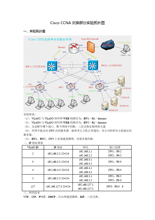
Cisco CCNA交换部分实验拓扑图一、实验拓扑图实验要求:(1)、VLAN2与VLAN3到外网WEB的路径为:RW1—R1—Internet(2)、VLAN4与VLAN5到外网WEB的路径为:RW2—R1—Internet(3)、无论断开哪个端口,整个网络不间断,三层交换实现网络互通(4)、外网不能访问SW3内的服务器,能和其它主机正常通信;本公司的所有主机能访问服务器。
(5)、RW1、RW2、SW3上实现通道捆绑,实现负载均衡。
VTP、STP、PVST、DHCP、以太网通道捆绑、RIP、三层交换。
四、详细配置清单(分段详解)(1)、VTP:RW1:RW1(config)#vtp domain Tang #RW1作为VTP服务器,设置域RW1(config)#vtp prunning 名为TangRW1(config)#vtp version 2RW1#vlan databaseRW1(vlan)#vl 2RW1(vlan)#vl 3RW1(vlan)#vl 4RW1(vlan)#vl 5RW1(vlan)#vl 127RW1(config)#int ra f0/1 – 6RW1(config-rang-if)#switchport trunk encap dot1qRW1(config-rang-if)#sw mo trunkRW1(config)#int ra f0/1 – 2 #f0/1和f0/2进行捆绑在一起RW1(config-rang-if)channel-group 1 mode onRW1(config)#port-channel load-balance src-mac #基于源和目标MAC负载均衡RW1(config)#int ra f0/3– 4RW1(config-rang-if)channel-group 2 mode onRW1(config)#port-channel load-balance src-macRW2:RW2(config)#int ra f0/1 – 6RW2(config-rang-if)#switchport trunk encap dot1qRW2(config-rang-if)#sw mo trunkRW2config)#int ra f0/1 – 2RW2config-rang-if)# channel-group 1 mode onRW2config)#port-channel load-balance src-macRW2config)#int ra f0/3– 4RW2config-rang-if) # channel-group 3 mode onRW2(config)#port-channel load-balance src-macSW1:SW1(configt)#int f0/1SW1(configt)#sw mo trSW1(configt)#int f0/6SW1(configt)#sw mo trSW1#sh vtp status #查看SW1否学习到RW1的VLAN信息S1(config)#vtp mode client #将SW1设为VTP客户端模式SW1(configt)#int f0/2 #将每项端口加入到相应vlan中SW1(configt-if)#sw ac vl 2S1(configt)#int f0/3SW1(configt)#sw ac vl 3SW1(configt)#int f0/4SW1(configt-if)#sw ac vl 4SW1(configt)#int f0/5SW1(configt-if)#sw ac vl 5SW2:SW2(config)#int f0/4SW2(config)#isw mo trSW2(config)#int f0/1SW2(config)#isw mo trSW2#sh vtp status #查看SW2是否学习到RW1的VLAN信息SW2#s (config)#vtp mode client #将SW2为VTP客户端模式SW2(configt)#int f0/2 #将每项端口加入到相应vlan中SW2(configt-if)#sw ac vl 2SW2(configt)#int f0/3SW2(configt)#sw ac vl 5SW3:SW3(config)#int ra f0/2 – 3 #将f0/2和f0/3捆绑在一起,组号为3 SW3(config-if)#sw mo trSW3(config-if)#channel-group 3 mode onSW3(config)#port-channel load-balance src-macSW3(config)#int ra f0/5 – 6 #将f0/5和f0/6捆绑在一起,组号为2SW3(config-if)#sw mo trSW3(config-if)#channel-group 2 mode onSW3(config)#port-channel load-balance src-macSW3(config)#vtp domain 123 #SW3服务器群专用交换机,不让学习其它的vlan信SW3(config)#vtp mode transparent 息,为其将该交换机更改为透明模式SW3#vl da #创建vlan127,将所有服务器端口加入vlan127SW3(vlan)#vl 127SW3(config)#int ra f0/3 – 8SW3(config-if)#sw ac vl 127。
IPv6的静态路由实验
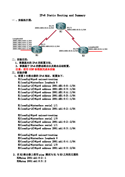
IPv6 Static Routing and Summary一 、实验拓扑图: R3R1R2Loopback02001:AB1:0:8::1/642001:AB1:0:9::1/642001:AB1:0:A::1/642001:AB1:0:B::1/642001:AB1:0:C::1/64S1/12001:AB1:0:2::1/64S1/02001:AB1:0:2::2/64S1/12001:AB1:0:3::1/64S1/02001:AB1:0:3::2/64Loopback02001:AB1:0:4::1/64二、实验目的:1、掌握基本的IPv6的配置方法。
2、掌握基于IPv6的静态路由以及路由总结配置。
注意:使用CCNP 标准版完成本实验三、实验步骤1、配置3台路由器的IPv6地址,配置如下:R1(config)#ipv6 unicast-routingR1(config)#interface loopback 0R1(config-if)#ipv6 address 2001:AB1:0:8::1/64R1(config-if)#ipv6 address 2001:AB1:0:9::1/64R1(config-if)#ipv6 address 2001:AB1:0:A::1/64R1(config-if)#ipv6 address 2001:AB1:0:B::1/64R1(config-if)#ipv6 address 2001:AB1:0:C::1/64R1(config)#interface serial 1/1R1(config-if)#ipv6 address 2001:ab1:0:2::1/64R2(config)#ipv6 unicast-routingR2(config)#interface serial 1/0R2(config-if)#ipv6 address 2001:ab1:0:2::2/64R2(config)#interface serial 1/1R2(config-if)#ipv6 address 2001:ab1:0:3::1/64R3(config)#ipv6 unicast-routingR3(config)#interface loopback 0R3(config-if)#ipv6 address 2001:ab1:0:4::1/64R3(config)#interface serial 1/0R3(config-if)#ipv6 address 2001:ab1:0:3::2/642、在R2路由器上使用ping 测试与R1与R3之间的互通性R2#ping 2001:ab1:0:2::1R2#ping 2001:ab1:0:3::23、查看R1的路由表R1#show ipv6 routeIPv6 Routing Table - 14 entriesC 2001:AB1:0:2::/64 [0/0]via ::, Serial1/1 C关键字前缀指出本地连接的网段L 2001:AB1:0:2::1/128 [0/0]via ::, Serial1/1C 2001:AB1:0:8::/64 [0/0]via ::, Loopback0L 2001:AB1:0:8::1/128 [0/0]via ::, Loopback0 L关键字前缀指出此为本地直接主机地址C 2001:AB1:0:9::/64 [0/0]via ::, Loopback0L 2001:AB1:0:9::1/128 [0/0]via ::, Loopback0C 2001:AB1:0:A::/64 [0/0]via ::, Loopback0L 2001:AB1:0:A::1/128 [0/0]via ::, Loopback0C 2001:AB1:0:B::/64 [0/0]via ::, Loopback0L 2001:AB1:0:B::1/128 [0/0]via ::, Loopback0C 2001:AB1:0:C::/64 [0/0]via ::, Loopback0L 2001:AB1:0:C::1/128 [0/0]via ::, Loopback0L FE80::/10 [0/0]via ::, Null0FE80地址前缀为链路本地单播地址,主要用于OSPF路由协议更新时作为其更新的源址L FF00::/8 [0/0]via ::, Null0 多播地址4、在所有路由器上配置到其他非直连网络的静态路由,配置如下:R1(config)#ipv6 route 2001:ab1:0:3::/64 2001:ab1:0:2::2R1(config)#ipv6 route 2001:ab1:0:4::/64 2001:ab1:0:2::2R2(config)#ipv6 route 2001:ab1:0:4::/64 2001:ab1:0:3::2 R3回环口路由R2(config)#ipv6 route 2001:ab1:0:8::/62 2001:ab1:0:2::1 R1回环口的汇总路由R2(config)#ipv6 route 2001:ab1:0:c::/62 2001:ab1:0:2::1 R1回环不可汇总路由R3(config)#ipv6 route ::/0 2001:ab1:0:3::1配置静态默认路由,简化路由配置5、查看R2上的路由表R2#show ipv6 routeIPv6 Routing Table - 9 entriesC 2001:AB1:0:2::/64 [0/0]via ::, Serial1/0L 2001:AB1:0:2::2/128 [0/0]via ::, Serial1/0C 2001:AB1:0:3::/64 [0/0]via ::, Serial1/1L 2001:AB1:0:3::1/128 [0/0]via ::, Serial1/1S 2001:AB1:0:4::/64 [1/0]via 2001:AB1:0:3::2S 2001:AB1:0:8::/62 [1/0]via 2001:AB1:0:2::1S 2001:AB1:0:C::/62 [1/0]via 2001:AB1:0:2::1 手工配置的静态路由,AD为1L FE80::/10 [0/0]via ::, Null0L FF00::/8 [0/0]via ::, Null06、测试静态路由的有效性R3#ping 2001:ab1:0:9::1Type escape sequence to abort.Sending 5, 100-byte ICMP Echos to 2001:AB1:0:9::1, timeout is 2 seconds: !!!!!Success rate is 100 percent (5/5), round-trip min/avg/max = 76/88/112 ms。
尚观ccnp 实验手册
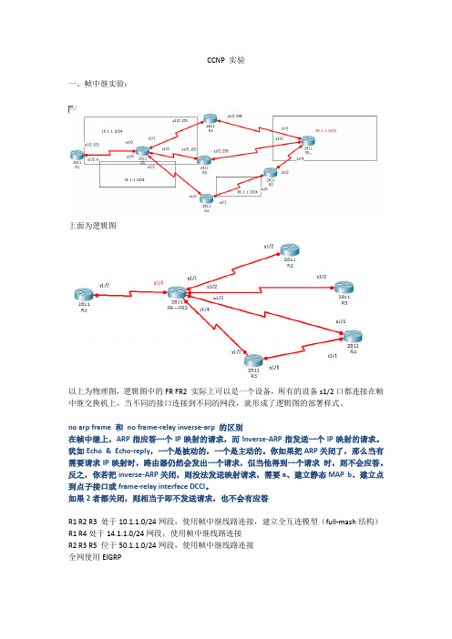
CCNP 实验一、帧中继实验:上面为逻辑图以上为物理图,逻辑图中的FR FR2 实际上可以是一个设备,所有的设备s1/2口都连接在帧中继交换机上,当不同的接口连接到不同的网段,就形成了逻辑图的部署样式。
no arp frame 和no frame-relay inverse-arp 的区别在帧中继上,ARP指应答一个IP映射的请求,而Inverse-ARP指发送一个IP映射的请求。
犹如Echo & Echo-reply,一个是被动的,一个是主动的。
你如果把ARP关闭了,那么当有需要请求IP映射时,路由器仍然会发出一个请求,但当他得到一个请求时,则不会应答。
反之,你若把inverse-ARP关闭,则没法发送映射请求,需要a、建立静态MAP b、建立点到点子接口或frame-relay interface DCCI。
如果2者都关闭,则相当于即不发送请求,也不会有应答R1 R2 R3 处于10.1.1.0/24网段,使用帧中继线路连接,建立全互连模型(full-mash结构)R1 R4处于14.1.1.0/24网段,使用帧中继线路连接R2 R3 R5 位于50.1.1.0/24网段,使用帧中继线路连接全网使用EIGRP基本配置:根据题目的要求,R1 连接R2和R3,全互连,则需要在R1 R2 R3配置多点子接口R1 连接R4是唯一一条线路,可以使用点到点子接口,也可以使用多点子接口R2 R3 同时连接R1 R5,可以采用多点子接口的方法。
在帧中继中,使用RIP 或者EIGRP时物理接口的水平分割默认关闭,是不生效的而多点子接口的水平分割默认开启,是生效的,而点到点子接口是不受水平分割影响的。
R1配置:Router(config)#line console 0Router(config-line)#exec-timeout 0 0Router(config-line)#logging synchronousRouter(config-line)#exitRouter(config)#no ip do loRouter(config)#ho R1R1(config)#interface loopback 0R1(config-if)#ip address 1.1.1.1 255.255.255.255R1(config-if)#no shutdownR1(config-if)#exitR1(config)#interface s1/2 // 要使用子接口,先设置物理接口R1(config-if)#encapsulation frame-relay //为接口进行帧中继封装R1(config-if)#no frame-relay inverse-arp //关闭帧中继逆向ARPR1(config-if)#no arp frame-relay //关闭ARPR1(config-if)#no shutdownR1(config-if)#exitR1(config)#interface s1/2.123 multipoint //这里R1对应R2、R3全互连,因此开启多点子接口特性R1(config-subif)#no frame-relay inverse-arpR1(config-subif)#no arp frame-relayR1(config-subif)#ip address 10.1.1.1 255.255.255.0R1(config-subif)#frame-relay map ip 10.1.1.2 102 broadcast //配置R1 到R2的映射R1(config-subif)#frame-relay map ip 10.1.1.3 103 broadcast //配置R1 到R3的映射R1(config-subif)#no shutdownR1(config-subif)#exitR1(config)#interface s1/2.4 point-to-point //R1到R4是唯一的,可以开启点到点子接口R1(config-subif)#no frame-relay inverse-arpR1(config-subif)#no arp frame-relayR1(config-subif)#ip address 14.1.1.1 255.255.255.0R1(config-subif)#frame-relay interface-dlci 104 //为点到点接口设置本地DLCIR1(config-fr-dlci)#exitR1(config-subif)#no shutdownR1(config-subif)#exitR2配置:Router>enableRouter(config)# line console 0Router(config-line)# exec-timeout 0 0Router(config-line)# logging synchronousRouter(config-line)# exitRouter(config)# no ip do loRouter(config)# ho R2R2(config)#interface loopback 0R2(config-if)#ip address 2.2.2.2 255.255.255.25R2(config-if)#no shutdownR2(config-if)#exitR2(config)#interface s1/2R2(config-if)#encapsulation frame-relayR2(config-if)#no frame-relay inverse-arpR2(config-if)#no arp frame-relayR2(config-if)#no shutdownR2(config-if)#exitR2(config)#interface s1/2.123 multipointR2(config-subif)#no frame-relay inverse-arpR2(config-subif)#no arp frame-relayR2(config-subif)#ip address 10.1.1.2 255.255.255.0R2(config-subif)#frame-relay map ip 10.1.1.1 201 broadcast //映射的书写一定是目标的IP本地的DLCIR2(config-subif)#frame-relay map ip 10.1.1.3 203 broadcastR2(config-subif)#no shutdownR2(config-subif)#exitR2(config)#interface s1/2.235 multipointR2(config-subif)#no frame-relay inverse-arpR2(config-subif)#no arp frame-relayR2(config-subif)#ip address 50.1.1.2 255.255.255.0R2(config-subif)#frame-relay map ip 50.1.1.5 205 broadcastR2(config-subif)#frame-relay map ip 50.1.1.3 205 broadcastR2(config-subif)#no shutdownR2(config-subif)#exitR3配置:Router>enableRouter#config terminalRouter(config)# line console 0Router(config-line)# exec-timeout 0 0Router(config-line)# logging synchronousRouter(config-line)# exitRouter(config)# no ip do loRouter(config)# ho R3R3(config)#interface lo0R3(config-if)#ip address 3.3.3.3 255.255.255.255R3(config-if)#no shutdownR3(config-if)#exitR3(config)#interface s1/2R3(config-if)#encapsulation frame-relayR3(config-if)#no frame-relay inverse-arpR3(config-if)#no arp frame-relayR3(config-if)#no shutdownR3(config-if)#exitR3(config)#interface s1/2.123 multipointR3(config-subif)#no frame-relay inverse-arpR3(config-subif)#no arp frame-relayR3(config-subif)#ip address 10.1.1.3 255.255.255.0R3(config-subif)#frame-relay map ip 10.1.1.1 301 broadcastR3(config-subif)#frame-relay map ip 10.1.1.2 302 broadcastR3(config-subif)#no shutdownR3(config-subif)#exitR3(config)#interface s1/2.235 multipointR3(config-subif)#no frame-relay inverse-arpR3(config-subif)#no arp frame-relayR3(config-subif)#ip address 50.1.1.3 255.255.255.0R3(config-subif)#frame-relay map ip 50.1.1.5 305 broadcastR3(config-subif)#frame-relay map ip 50.1.1.2 305 broadcastR3(config-subif)#no shutdownR3(config-subif)#exitR4配置:Router>enableRouter#config terEnter configuration commands, one per line. End with CNTL/Z.Router(config)# line console 0Router(config-line)# exec-timeout 0 0Router(config-line)# logging synchronousRouter(config-line)# exitRouter(config)# no ip do loRouter(config)# ho R4R4(config)#interface lo0R4(config-if)#ip address 4.4.4.4 255.255.255.255R4(config-if)#no shutdownR4(config-if)#exitR4(config)#interface s1/2R4(config-if)#encapsulation frame-relayR4(config-if)#no frame-relay inverse-arpR4(config-if)#no arp frame-relayR4(config-if)#ip address 14.1.1.4 255.255.255.0R4(config-if)#frame-relay map ip 14.1.1.1 401 broadcastR4(config-if)#no shutdownR4(config-if)#exitR4(config)#interface s1/1R4(config-if)#ip address 45.1.1.4 255.255.255.0R4(config-if)#no shutdownR4(config-if)#exitR5配置:Router>enableRouter#config terminalEnter configuration commands, one per line. End with CNTL/Z. Router(config)# line console 0Router(config-line)# exec-timeout 0 0Router(config-line)# logging synchronousRouter(config-line)# exitRouter(config)# no ip do loRouter(config)# ho R5R5(config)#interface lo0R5(config-if)#ip address 5.5.5.5 255.255.255.255R5(config-if)#no shutdownR5(config-if)#exitR5(config)#interface s1/2R5(config-if)#encapsulation frame-relayR5(config-if)#no frame-relay inverse-arpR5(config-if)#no arp frame-relayR5(config-if)#ip address 50.1.1.5 255.255.255.0R5(config-if)#frame-relay map ip 50.1.1.2 502 broadcast R5(config-if)#frame-relay map ip 50.1.1.3 503 broadcast R5(config-if)#no shutdownR5(config-if)#exitR5(config)#interface s1/0R5(config-if)#ip address 45.1.1.5 255.255.255.0R5(config-if)#no shutdownR5(config-if)#exit配置路由协议,并注意关闭EIGRP的水平分割R1配置:R1(config)#router eigrp 100R1(config-router)#no auto-summaryR1(config-router)#network 1.1.1.1 0.0.0.0R1(config-router)#network 10.1.1.0 0.0.0.255R1(config-router)#network 14.1.1.0 0.0.0.255R1(config-router)#exitR1(config)#interface s1/2R1(config-if)#no ip split-horizonR1(config-if)#no ip split-horizon eigrp 100R1(config-if)#exitR2配置:R2(config)#router eigrp 100R2(config-router)#no auto-summaryR2(config-router)#network 2.2.2.2 0.0.0.0R2(config-router)#network 10.1.1.0 0.0.0.255R2(config-router)#network 50.1.1.0 0.0.0.255R2(config-router)#exitR2(config)#interface s1/2R2(config-if)#no ip split-horizonR2(config-if)#no ip split-horizon eigrp 100R2(config-if)#exitR3配置:R3(config)#router eigrp 100R3(config-router)#no auto-summaryR3(config-router)#network 3.3.3.3 0.0.0.0R3(config-router)#network 10.1.1.0 0.0.0.255R3(config-router)#network 50.1.1.0 0.0.0.255R3(config-router)#exitR3(config)#interface s1/2R3(config-if)#no ip split-horizonR3(config-if)#no ip split-horizon eigrp 100R3(config-if)#exitR4配置:R4(config)#router eigrp 100R4(config-router)#no auto-summaryR4(config-router)#network 4.4.4.4 0.0.0.0R4(config-router)# network 45.1.1.0 0.0.0.255R4(config-router)#network 14.1.1.0 0.0.0.255R4(config-router)#exitR5配置:R5(config)#router eigrp 100R5(config-router)#no auto-summaryR5(config-router)#network 5.5.5.5 0.0.0.0R5(config-router)#network 50.1.1.0 0.0.0.255R5(config-router)#network 45.1.1.0 0.0.0.255R5(config-router)#exit进行检查:R1 配置:R1#sho frame-relay mapSerial1/2.123 (up): ip 10.1.1.2 dlci 102(0x66,0x1860), static, //这条映射是手工书写的broadcast,CISCO, status defined, activeSerial1/2.123 (up): ip 10.1.1.3 dlci 103(0x67,0x1870), static, //目标IP为10.1.1.3 本地DLCI 103 broadcast, //开启了伪广播特性CISCO, status defined, active //vc的状态现在是正常的Serial1/2.4 (up): point-to-point dlci, dlci 104(0x68,0x1880), broadcast //这是个点到点子接口status defined, activeR1#sho ip eigrp neighborsIP-EIGRP neighbors for process 100H Address Interface Hold Uptime SRTT RTO Q Seq(sec) (ms) Cnt Num 2 14.1.1.4 Se1/2.4 173 00:08:37 53 318 0 91 10.1.1.3 Se1/2.123 129 00:10:03 43 258 0 100 10.1.1.2 Se1/2.123 173 00:11:17 49 294 0 9R1#sho ip routeCodes: C - connected, S - static, R - RIP, M - mobile, B - BGPD - EIGRP, EX - EIGRP external, O - OSPF, IA - OSPF inter areaN1 - OSPF NSSA external type 1, N2 - OSPF NSSA external type 2E1 - OSPF external type 1, E2 - OSPF external type 2i - IS-IS, su - IS-IS summary, L1 - IS-IS level-1, L2 - IS-IS level-2ia - IS-IS inter area, * - candidate default, U - per-user static routeo - ODR, P - periodic downloaded static routeGateway of last resort is not set1.0.0.0/32 is subnetted, 1 subnetsC 1.1.1.1 is directly connected, Loopback050.0.0.0/24 is subnetted, 1 subnetsD 50.1.1.0 [90/2681856] via 10.1.1.3, 00:00:55, Serial1/2.123[90/2681856] via 10.1.1.2, 00:00:55, Serial1/2.1232.0.0.0/32 is subnetted, 1 subnetsD 2.2.2.2 [90/2297856] via 10.1.1.2, 00:00:55, Serial1/2.1233.0.0.0/32 is subnetted, 1 subnetsD 3.3.3.3 [90/2297856] via 10.1.1.3, 00:00:55, Serial1/2.1234.0.0.0/32 is subnetted, 1 subnetsD 4.4.4.4 [90/2297856] via 14.1.1.4, 00:00:55, Serial1/2.45.0.0.0/32 is subnetted, 1 subnetsD 5.5.5.5 [90/2809856] via 10.1.1.3, 00:00:55, Serial1/2.123[90/2809856] via 10.1.1.2, 00:00:55, Serial1/2.123[90/2809856] via 14.1.1.4, 00:00:55, Serial1/2.410.0.0.0/24 is subnetted, 1 subnetsC 10.1.1.0 is directly connected, Serial1/2.12314.0.0.0/24 is subnetted, 1 subnetsC 14.1.1.0 is directly connected, Serial1/2.445.0.0.0/24 is subnetted, 1 subnetsD 45.1.1.0 [90/2681856] via 14.1.1.4, 00:00:55, Serial1/2.4R1#R2配置:R2#sho frame-relay mapSerial1/2.123 (up): ip 10.1.1.1 dlci 201(0xC9,0x3090), static,broadcast,CISCO, status defined, activeSerial1/2.123 (up): ip 10.1.1.3 dlci 203(0xCB,0x30B0), static,broadcast,CISCO, status defined, activeSerial1/2.235 (up): ip 50.1.1.3 dlci 205(0xCD,0x30D0), static,broadcast,CISCO, status defined, activeSerial1/2.235 (up): ip 50.1.1.5 dlci 205(0xCD,0x30D0), static,broadcast,CISCO, status defined, activeR2#R2#sho ip eigrp neighborsIP-EIGRP neighbors for process 100H Address Interface Hold Uptime SRTT RTO Q Seq(sec) (ms) Cnt Num 2 50.1.1.5 Se1/2.235 157 00:08:27 67 402 0 71 10.1.1.3 Se1/2.123 145 00:10:43 42 252 0 100 10.1.1.1 Se1/2.123 144 00:11:39 41 246 0 13R2#R2#sho ip rR2#sho ip routeCodes: C - connected, S - static, R - RIP, M - mobile, B - BGPD - EIGRP, EX - EIGRP external, O - OSPF, IA - OSPF inter areaN1 - OSPF NSSA external type 1, N2 - OSPF NSSA external type 2E1 - OSPF external type 1, E2 - OSPF external type 2i - IS-IS, su - IS-IS summary, L1 - IS-IS level-1, L2 - IS-IS level-2ia - IS-IS inter area, * - candidate default, U - per-user static routeo - ODR, P - periodic downloaded static routeGateway of last resort is not set1.0.0.0/32 is subnetted, 1 subnetsD 1.1.1.1 [90/2297856] via 10.1.1.1, 00:11:40, Serial1/2.12350.0.0.0/24 is subnetted, 1 subnetsC 50.1.1.0 is directly connected, Serial1/2.2352.0.0.0/32 is subnetted, 1 subnetsC 2.2.2.2 is directly connected, Loopback03.0.0.0/32 is subnetted, 1 subnetsD 3.3.3.3 [90/2297856] via 10.1.1.3, 00:10:05, Serial1/2.1234.0.0.0/32 is subnetted, 1 subnetsD 4.4.4.4 [90/2809856] via 10.1.1.1, 00:08:09, Serial1/2.123[90/2809856] via 50.1.1.5, 00:08:09, Serial1/2.2355.0.0.0/32 is subnetted, 1 subnetsD 5.5.5.5 [90/2297856] via 50.1.1.5, 00:02:13, Serial1/2.23510.0.0.0/24 is subnetted, 1 subnetsC 10.1.1.0 is directly connected, Serial1/2.12314.0.0.0/24 is subnetted, 1 subnetsD 14.1.1.0 [90/2681856] via 10.1.1.1, 00:08:09, Serial1/2.12345.0.0.0/24 is subnetted, 1 subnetsD 45.1.1.0 [90/2681856] via 50.1.1.5, 00:02:14, Serial1/2.235R2#R3 配置:R3#sho frame-relay mapSerial1/2.123 (up): ip 10.1.1.1 dlci 301(0x12D,0x48D0), static,broadcast,CISCO, status defined, activeSerial1/2.123 (up): ip 10.1.1.2 dlci 302(0x12E,0x48E0), static,broadcast,CISCO, status defined, activeSerial1/2.235 (up): ip 50.1.1.2 dlci 305(0x131,0x4C10), static,broadcast,CISCO, status defined, activeSerial1/2.235 (up): ip 50.1.1.5 dlci 305(0x131,0x4C10), static,broadcast,CISCO, status defined, activeR3#sho ip eigrp neighborsIP-EIGRP neighbors for process 100H Address Interface Hold Uptime SRTT RTO Q Seq(sec) (ms) Cnt Num 2 50.1.1.5 Se1/2.235 161 00:03:01 8 200 0 71 10.1.1.2 Se1/2.123 145 00:10:49 53 318 0 90 10.1.1.1 Se1/2.123 149 00:11:29 322 1932 0 13R3#R3#sho ip routeCodes: C - connected, S - static, R - RIP, M - mobile, B - BGPD - EIGRP, EX - EIGRP external, O - OSPF, IA - OSPF inter areaN1 - OSPF NSSA external type 1, N2 - OSPF NSSA external type 2E1 - OSPF external type 1, E2 - OSPF external type 2i - IS-IS, su - IS-IS summary, L1 - IS-IS level-1, L2 - IS-IS level-2ia - IS-IS inter area, * - candidate default, U - per-user static routeo - ODR, P - periodic downloaded static routeGateway of last resort is not set1.0.0.0/32 is subnetted, 1 subnetsD 1.1.1.1 [90/2297856] via 10.1.1.1, 00:11:30, Serial1/2.12350.0.0.0/24 is subnetted, 1 subnetsC 50.1.1.0 is directly connected, Serial1/2.2352.0.0.0/32 is subnetted, 1 subnetsD 2.2.2.2 [90/2297856] via 10.1.1.2, 00:10:48, Serial1/2.1233.0.0.0/32 is subnetted, 1 subnetsC 3.3.3.3 is directly connected, Loopback04.0.0.0/32 is subnetted, 1 subnetsD 4.4.4.4 [90/2809856] via 10.1.1.1, 00:03:00, Serial1/2.123[90/2809856] via 50.1.1.5, 00:03:00, Serial1/2.2355.0.0.0/32 is subnetted, 1 subnetsD 5.5.5.5 [90/2297856] via 50.1.1.5, 00:03:00, Serial1/2.23510.0.0.0/24 is subnetted, 1 subnetsC 10.1.1.0 is directly connected, Serial1/2.12314.0.0.0/24 is subnetted, 1 subnetsD 14.1.1.0 [90/2681856] via 10.1.1.1, 00:03:00, Serial1/2.12345.0.0.0/24 is subnetted, 1 subnetsD 45.1.1.0 [90/2681856] via 50.1.1.5, 00:03:00, Serial1/2.235R3#R4配置:R4#sho frame-relay mapSerial1/2 (up): ip 14.1.1.1 dlci 401(0x191,0x6410), static,broadcast,CISCO, status defined, activeR4#sho ip eigrp neighborsIP-EIGRP neighbors for process 100H Address Interface Hold Uptime SRTT RTO Q Seq(sec) (ms) Cnt Num 1 45.1.1.5 Se1/1 14 00:09:50 60 360 0 80 14.1.1.1 Se1/2 12 00:10:58 542 3252 0 14R4#sho ip routeCodes: C - connected, S - static, R - RIP, M - mobile, B - BGPD - EIGRP, EX - EIGRP external, O - OSPF, IA - OSPF inter areaN1 - OSPF NSSA external type 1, N2 - OSPF NSSA external type 2E1 - OSPF external type 1, E2 - OSPF external type 2i - IS-IS, su - IS-IS summary, L1 - IS-IS level-1, L2 - IS-IS level-2ia - IS-IS inter area, * - candidate default, U - per-user static routeo - ODR, P - periodic downloaded static routeGateway of last resort is not set1.0.0.0/32 is subnetted, 1 subnetsD 1.1.1.1 [90/2297856] via 14.1.1.1, 00:10:58, Serial1/250.0.0.0/24 is subnetted, 1 subnetsD 50.1.1.0 [90/2681856] via 45.1.1.5, 00:09:49, Serial1/12.0.0.0/32 is subnetted, 1 subnetsD 2.2.2.2 [90/2809856] via 14.1.1.1, 00:09:49, Serial1/2[90/2809856] via 45.1.1.5, 00:09:49, Serial1/13.0.0.0/32 is subnetted, 1 subnetsD 3.3.3.3 [90/2809856] via 14.1.1.1, 00:04:00, Serial1/2[90/2809856] via 45.1.1.5, 00:04:00, Serial1/14.0.0.0/32 is subnetted, 1 subnetsC 4.4.4.4 is directly connected, Loopback05.0.0.0/32 is subnetted, 1 subnetsD 5.5.5.5 [90/2297856] via 45.1.1.5, 00:09:49, Serial1/110.0.0.0/24 is subnetted, 1 subnetsD 10.1.1.0 [90/2681856] via 14.1.1.1, 00:09:49, Serial1/214.0.0.0/24 is subnetted, 1 subnetsC 14.1.1.0 is directly connected, Serial1/245.0.0.0/24 is subnetted, 1 subnetsC 45.1.1.0 is directly connected, Serial1/1R5配置:R5#sho frame-relay mapSerial1/2 (up): ip 50.1.1.2 dlci 502(0x1F6,0x7C60), static,broadcast,CISCO, status defined, activeSerial1/2 (up): ip 50.1.1.3 dlci 503(0x1F7,0x7C70), static,broadcast,CISCO, status defined, activeR5#*Apr 1 23:49:15.627: %SYS-5-CONFIG_I: Configured from console by consoleR5#R5#sho ip eigrp neighborsIP-EIGRP neighbors for process 100H Address Interface Hold Uptime SRTT RTO Q Seq(sec) (ms) Cnt Num 2 50.1.1.3 Se1/2 149 00:05:04 20 200 0 91 45.1.1.4 Se1/0 11 00:10:38 68 408 0 100 50.1.1.2 Se1/2 161 00:10:43 42 252 0 10R5#R5#sho ip routeCodes: C - connected, S - static, R - RIP, M - mobile, B - BGPD - EIGRP, EX - EIGRP external, O - OSPF, IA - OSPF inter areaN1 - OSPF NSSA external type 1, N2 - OSPF NSSA external type 2E1 - OSPF external type 1, E2 - OSPF external type 2i - IS-IS, su - IS-IS summary, L1 - IS-IS level-1, L2 - IS-IS level-2ia - IS-IS inter area, * - candidate default, U - per-user static routeo - ODR, P - periodic downloaded static routeGateway of last resort is not set1.0.0.0/32 is subnetted, 1 subnetsD 1.1.1.1 [90/2809856] via 50.1.1.2, 00:04:48, Serial1/2[90/2809856] via 45.1.1.4, 00:04:48, Serial1/0[90/2809856] via 50.1.1.3, 00:04:48, Serial1/250.0.0.0/24 is subnetted, 1 subnetsC 50.1.1.0 is directly connected, Serial1/22.0.0.0/32 is subnetted, 1 subnetsD 2.2.2.2 [90/2297856] via 50.1.1.2, 00:04:48, Serial1/23.0.0.0/32 is subnetted, 1 subnetsD 3.3.3.3 [90/2297856] via 50.1.1.3, 00:04:48, Serial1/24.0.0.0/32 is subnetted, 1 subnetsD 4.4.4.4 [90/2297856] via 45.1.1.4, 00:04:44, Serial1/05.0.0.0/32 is subnetted, 1 subnetsC 5.5.5.5 is directly connected, Loopback010.0.0.0/24 is subnetted, 1 subnetsD 10.1.1.0 [90/2681856] via 50.1.1.2, 00:04:48, Serial1/2[90/2681856] via 50.1.1.3, 00:04:48, Serial1/214.0.0.0/24 is subnetted, 1 subnetsD 14.1.1.0 [90/2681856] via 45.1.1.4, 00:04:48, Serial1/045.0.0.0/24 is subnetted, 1 subnetsC 45.1.1.0 is directly connected, Serial1/0R5#使用OSPF,需求同上面的实验R1配置:Router(config)#line console 0Router(config-line)#exec-timeout 0 0Router(config-line)#logging synchronousRouter(config-line)#exitRouter(config)#no ip do loRouter(config)#ho R1R1(config)#interface loopback 0R1(config-if)#ip address 1.1.1.1 255.255.255.255R1(config-if)#no shutdownR1(config-if)#exitR1(config)#interface s1/2 // 要使用子接口,先设置物理接口R1(config-if)#encapsulation frame-relay //为接口进行帧中继封装R1(config-if)#no frame-relay inverse-arp //关闭帧中继逆向ARPR1(config-if)#no arp frame-relay //关闭ARPR1(config-if)#no shutdownR1(config-if)#exitR1(config)#interface s1/2.123 multipoint //这里R1对应R2、R3全互连,因此开启多点子接口特性R1(config-subif)#no frame-relay inverse-arpR1(config-subif)#no arp frame-relayR1(config-subif)#ip address 10.1.1.1 255.255.255.0R1(config-subif)#frame-relay map ip 10.1.1.2 102 broadcast //配置R1 到R2的映射R1(config-subif)#frame-relay map ip 10.1.1.3 103 broadcast //配置R1 到R3的映射R1(config-subif)#no shutdownR1(config-subif)#exitR1(config)#interface s1/2.4 point-to-point //R1到R4是唯一的,可以开启点到点子接口R1(config-subif)#no frame-relay inverse-arpR1(config-subif)#no arp frame-relayR1(config-subif)#ip address 14.1.1.1 255.255.255.0R1(config-subif)#frame-relay interface-dlci 104 //为点到点接口设置本地DLCIR1(config-fr-dlci)#exitR1(config-subif)#no shutdownR1(config-subif)#exitR2配置:Router>enableRouter(config)# line console 0Router(config-line)# exec-timeout 0 0Router(config-line)# logging synchronousRouter(config-line)# exitRouter(config)# no ip do loRouter(config)# ho R2R2(config)#interface loopback 0R2(config-if)#ip address 2.2.2.2 255.255.255.25R2(config-if)#no shutdownR2(config-if)#exitR2(config)#interface s1/2R2(config-if)#encapsulation frame-relayR2(config-if)#no frame-relay inverse-arpR2(config-if)#no arp frame-relayR2(config-if)#no shutdownR2(config-if)#exitR2(config)#interface s1/2.123 multipointR2(config-subif)#no frame-relay inverse-arpR2(config-subif)#no arp frame-relayR2(config-subif)#ip address 10.1.1.2 255.255.255.0R2(config-subif)#frame-relay map ip 10.1.1.1 201 broadcast //映射的书写一定是目标的IP本地的DLCIR2(config-subif)#frame-relay map ip 10.1.1.3 203 broadcastR2(config-subif)#no shutdownR2(config-subif)#exitR2(config)#interface s1/2.235 multipointR2(config-subif)#no frame-relay inverse-arpR2(config-subif)#no arp frame-relayR2(config-subif)#ip address 50.1.1.2 255.255.255.0R2(config-subif)#frame-relay map ip 50.1.1.5 205 broadcastR2(config-subif)#frame-relay map ip 50.1.1.3 205 broadcastR2(config-subif)#no shutdownR2(config-subif)#exitR3配置:Router>enableRouter#config terminalRouter(config)# line console 0Router(config-line)# exec-timeout 0 0Router(config-line)# logging synchronousRouter(config-line)# exitRouter(config)# no ip do loRouter(config)# ho R3R3(config)#interface lo0R3(config-if)#ip address 3.3.3.3 255.255.255.255R3(config-if)#no shutdownR3(config-if)#exitR3(config)#interface s1/2R3(config-if)#encapsulation frame-relayR3(config-if)#no frame-relay inverse-arpR3(config-if)#no arp frame-relayR3(config-if)#no shutdownR3(config-if)#exitR3(config)#interface s1/2.123 multipointR3(config-subif)#no frame-relay inverse-arpR3(config-subif)#no arp frame-relayR3(config-subif)#ip address 10.1.1.3 255.255.255.0R3(config-subif)#frame-relay map ip 10.1.1.1 301 broadcast R3(config-subif)#frame-relay map ip 10.1.1.2 302 broadcast R3(config-subif)#no shutdownR3(config-subif)#exitR3(config)#interface s1/2.235 multipointR3(config-subif)#no frame-relay inverse-arpR3(config-subif)#no arp frame-relayR3(config-subif)#ip address 50.1.1.3 255.255.255.0R3(config-subif)#frame-relay map ip 50.1.1.5 305 broadcast R3(config-subif)#frame-relay map ip 50.1.1.2 305 broadcast R3(config-subif)#no shutdownR3(config-subif)#exitR4配置:Router>enableRouter#config terEnter configuration commands, one per line. End with CNTL/Z. Router(config)# line console 0Router(config-line)# exec-timeout 0 0Router(config-line)# logging synchronousRouter(config-line)# exitRouter(config)# no ip do loRouter(config)# ho R4R4(config)#interface lo0R4(config-if)#ip address 4.4.4.4 255.255.255.255R4(config-if)#no shutdownR4(config-if)#exitR4(config)#interface s1/2R4(config-if)#encapsulation frame-relayR4(config-if)#no frame-relay inverse-arpR4(config-if)#no arp frame-relayR4(config-if)#ip address 14.1.1.4 255.255.255.0R4(config-if)#frame-relay map ip 14.1.1.1 401 broadcastR4(config-if)#no shutdownR4(config-if)#exitR4(config)#interface s1/1R4(config-if)#ip address 45.1.1.4 255.255.255.0R4(config-if)#no shutdownR4(config-if)#exitR5配置:Router>enableRouter#config terminalEnter configuration commands, one per line. End with CNTL/Z. Router(config)# line console 0Router(config-line)# exec-timeout 0 0Router(config-line)# logging synchronousRouter(config-line)# exitRouter(config)# no ip do loRouter(config)# ho R5R5(config)#interface lo0R5(config-if)#ip address 5.5.5.5 255.255.255.255R5(config-if)#no shutdownR5(config-if)#exitR5(config)#interface s1/2R5(config-if)#encapsulation frame-relayR5(config-if)#no frame-relay inverse-arpR5(config-if)#no arp frame-relayR5(config-if)#ip address 50.1.1.5 255.255.255.0R5(config-if)#frame-relay map ip 50.1.1.2 502 broadcastR5(config-if)#frame-relay map ip 50.1.1.3 503 broadcastR5(config-if)#no shutdownR5(config-if)#exitR5(config)#interface s1/0R5(config-if)#ip address 45.1.1.5 255.255.255.0R5(config-if)#no shutdownR5(config-if)#exit配置路由协议:OSPF的接口网络类型如下,邻居关系的建立,DR/BDR 都会收到接口网络类型的影响由于默认情况下,帧中继网络中接口的默认网络类型为NBMA类型,因此在我们的网络中R1—R2—R3之间的链路之间不能正常自动建立邻居关系;R2---R3—R5也如此,无法建立邻居关系;R1—R4 由于接口类型不同导致hello时间不同,也无法建立邻居关系。
[福建金科]ccnprouteospf综合实验
![[福建金科]ccnprouteospf综合实验](https://img.taocdn.com/s3/m/14c30d6128ea81c758f578f9.png)
CCNP ROUTE OSPF综合实验一、实验目的掌握OSPF的配置命令,学会应用一些OSPF的高级功能,如虚链路,手动指定网络类型,帧中继环境中的OSPF配置,OSPF选路的修改,完全末梢区的配置,OSPF区域验证,手动汇总,默认路由的传递。
二、实验拓扑实验背景假定著名医生拥有一些地方性的事务所,每个事务所专门研究牙科的某个特定领域,如牙根管填弃手术,补牙等等。
希望通过一个帧中继网络将他的这些事务所连接起来.这些事务所同时还希望通过共享一个公用连接实现与Internet互联,这样他们才能及时获取牙科新技术的最新发展动态.要求按照下列标准配置一个OSPF网络。
三、实验需求:1.配置一个IP网络,实验逻辑图如图,IP地址由IP地址规划而定。
2.路由协议采用OSPF,进程ID为2014,RID为loopback0地址。
3.模拟帧中继环境,PVC如图所示(现实中这由ISP提供商提供)。
4.将与帧中继相连的三个事务所配置成广播型,共子网:/28,其中dental_ho(R66)事务所的路由器做为永久性DR,且采用子接口方式。
5.按照图示配置OSPF区域,其中crowns(R55),root_canals(R44),pain_center(R11)之间的区域要配置成完全末梢区域。
6.Orthopaedics(R22)是新收购的事务所,由于来不及布线施工而暂时并到surgery(R33)事务所,配置使得所有网络可达(ping测试)。
7.在dental_ho(R66)事务上配置使得所有访问internet的流量都指向网络其直连的以太网络,同时把这条路由告诉OSPF区域。
8.Area0基于安全的原因配置上MD5认证,密码:goldtech9.pain_center(R11)是事务所总部,将其做为指定路由器,与它直连的两个事务所邻居关系保持two-way状态。
10.为了减少网络流量,将pain_center(R11)所在区域汇总有主类网络通告出去。
ARP--CCNP Route教学课件

1ARP首先讲到ARP,ARP是地址解析协议,它的作用是在以太网环境下,通过3层的IP 地址来找寻2层的MAC地址,得到一张ARP缓存表。
转发数据的时候根据ARP缓存表来进行传输。
下图详细说明数据传输时ARP是如何一步步操作的。
在配置IP地址后,不做任何ping操作,ARP缓存表是这样的:当PC去ping R1的时候,你会发现第一个丢包了。
像这样R1#ping 192.168.1.2Type escape sequence to abort.Sending 5, 100-byte ICMP Echos to 192.168.1.2, timeout is 2 seconds:.!!!!Success rate is 100 percent (5/5), round-trip min/avg/max = 8/25/56 ms第一个包其实是做ARP请求去了。
PC发现ping的是本网段,会发出ARP广播,向R1请求192.168.1.2的MAC地址。
得到回应后ARP表会添加ARP请求得来的相应内容。
PC:这个时候PC再去ping 10.1.1.3会发现ping的不是本网段,由于PC没有路由功能所以不知道该往哪里发送,会按照之前已经配好的默认网关发送出去,一般默认网关会配置成路由器的接口IP,在这里是192.168.1.2。
查看ARP缓存表发现了192.168.1.2对应的MAC地址,就把包交给路由器处理了。
R1:路由器收到去往10.1.1.0网段的数据包会查询路由表,首先查看路由表发现数据该发往FastEthernet 0/1#show ip routeC 10.1.1.0 is directly connected, FastEthernet0/1然后查看ARP表是否有下一跳10.1.1.3的MAC地址信息,如果有则按MAC把数据发到下一跳;如果没有则发出ARP查询,查询后获得下一跳地址10.1.1.3的MAC地址,存到ARP缓存表中,然后转发。
CCNP902必考的6个实验(拓扑搭建,配置详解)

CCNP902 必考的 6 个实验
目录 CCNP902 必考的 6 个实验............................................................................................................... 1 一、 EIGRP-OSPF 重分发(配置 distance).................................................................................. 2 1.1 拓扑环境....................................................................................................................... 2 1.2 搭建实验环境............................................................................................................... 2 1.3 题目要求....................................................................................................................... 5 1) 不配置 distance,正常配置 .................................................................................... 5 2) 配置 dist
网络工程拓扑绘制规范版

Si
Si
Si
Si
GS_C3550_1 GS_C3550_2
GS_C3550_4
GS_C3550_3
Si
GS_C3550_1
Si
GS_C3550_2
Si
Si
GS_C3550_4
GS_C3550_3
绘制注意事项
• 先构图、再框架、接着设备和标示 • 图标大小、标示位置要合理 • 拓扑呈现完整、格式统一、布局整洁不凌乱 • 拓扑元素要规范
OSPF R5
50.50.50.0/24
工程环境测试拓扑
R1
R2
EIGRP
OSPF1
OSPF2
R4
RIPv2
R6
EBGP
R3
R7
RR
R9
RR
R5
EBGP
R8
绘制步骤
拓扑绘制步骤(建议)
1. 首先在纸上花个草稿,熟练之后,做到拓扑在心中 2. 通过辅助手段描绘拓扑框架,利用好线条和框架色块(可根据业务逻辑模块) 3. 放置网络设备图标 4. 标记信息元素 5. 完善外围元素 6. 完成整体绘制
Si
Si
宿舍楼1
…… 宿舍楼5
Si
办公楼
绘制示例
• 步骤6 完成拓扑
服务器群 WEB服务器 文件服务器
Si
教学楼
Internet
OR
Si
Si
ห้องสมุดไป่ตู้Si
Si
宿舍楼1
…… 宿舍楼5
Si
办公楼
小结
以上所谓步骤,只是提供一个拓扑绘制的大致思路,并非所有的拓扑都需 要照搬照抄上述步骤来完成,有些拓扑异常复杂,更非简单几步就能完成。 根据物理网络环境,结合客户业务逻辑结构,最终落地成逻辑的网络拓扑 图,其实体现的是工程师对客户网络环境、网络需求、网络协议等的综合 理解。
[IT认证]CCNPSwitchv10实验手册
![[IT认证]CCNPSwitchv10实验手册](https://img.taocdn.com/s3/m/0e551b1391c69ec3d5bbfd0a79563c1ec5dad7ae.png)
目录:1、VLAN创建 P32、交换机端口操作模式设置 P53、VLAN端口划分 P74、VTP设置 P85、STP实验 P126、PVST+&RSTP P157、STP防护 P178、SVI实验 P199、etherchannel P2110、HSRP P2411、DHCP P2712、dhcp中继 P2913、IP SLA实验 P3114、port-Security P3315、基于端口的802.1x P3516、dynamic ARP inspect P4117、VLAN ACL P43VLAN的创建一、实验目的1、掌握标准VLAN的创建方法2、掌握扩展VLAN的创建方法二、实验内容拓扑图:需求:为不同的客户划分VLAN三、实验配置配置:1、查看VTP的操作模式Switch#show vtp statusVTP Version : running VTP1 (VTP2 capable) Configuration Revision : 0Maximum VLANs supported locally : 1005Number of existing VLANs : 5VTP Operating Mode : ServerVTP Domain Name :2、配置标准VLANSwitch(vlan)#vlan databaseSwitch(vlan)#vlan 1 (创建VLAN 1)VLAN 1 modified:Switch(vlan)#vlan 2VLAN 2 added:Name: VLAN0002Switch(vlan)#vlan 3 name customer (创建VLAN ,并且设置VLAN的名字)VLAN 3 modified:Name: customerSwitch(vlan)#exit (一定要使用exit退出VLAN database)3、创建扩展VLAN(1006~4095)错误方式:Switch(vlan)#vlan 1006^% Invalid input detected at '^' marker.Switch(config)#vlan 1006Switch(config-vlan)#exit% Failed to create VLANs 1006Extended VLAN(s) not allowed in current VTP mode.(在VLAN Database中不能创建扩展VLAN,只能在配置模式下,并且是VTP透明模式下才能创建)正确方式:Switch(config)#vtp mode transparentSwitch(config)#vlan 1006验证:Switch#show vlan briefVLAN Name Status Ports---- -------------------------------- --------- -------------------------------1 default active Fa0/1, Fa0/2, Fa0/3, Fa0/4Fa0/5, Fa0/6, Fa0/7, Fa0/8Fa0/9, Fa0/10, Fa0/11, Fa0/122 VLAN0002 active3 customer active1002 fddi-default act/unsup1003 token-ring-default act/unsup1004 fddinet-default act/unsup1005 trnet-default act/unsup1006 VLAN1006 activeSwitch#show vtp statusVTP Version : running VTP1 (VTP2 capable)Configuration Revision : 0Maximum VLANs supported locally : 1005Number of existing VLANs : 7VTP Operating Mode : TransparentVTP Domain Name :四、应用场景在大型网络环境或在运营商网络环境下分配VLAN时要用到扩展VLAN(1006~4095)的情况下。
CCNP路由实验手册

First-lab CCNP路由实验手册Powered by CCIE# Wenjie Deng前导:所有的问题,都是技术问题!都可以搞定!自信心的力量让你可以超越一切,我们的思想可以跨越一切边界,人生的每一段经历,每一次努力都不会白费,加油吧!路由技术作为我们CCNP的重点课程之一,当然难度比起CCNA的课程有所加大,利用好自己学习的理论知识,在实验中好好发挥,有问题就抓住老师问个不放,尽量多使用检查命令,深入理解.注意所有的实验均为自己定制接口IP地址RIP实验实验目标:.深刻理解RIP协议的版本,汇总,认证等概念实验TOP图如下:IP地址:所有路由器的loopback0口均为139.1.x.x,例如R1为139.1.1.1 /24R2为139.1.2.2 以此类推题目未使用到的端口不必管它.所有FR的接口都必须使用静态映射除非题目说明不得更改RIP版本题目需求如下1.首先将所有的路由器都要以最小资源运行RIPV2.所有的路由器loopback0要全网可见2.R1 R2之间触发式更新(注意触发式更新必须在点到点链路上才可以运行)3.R3 R4之间要求为广播更新,且不得更改RIP版本4.R4上起12个loopback口(注意不要覆盖掉loopback0)IP为10.10.1.110.10.2.110.10.3.1一直到10.10.12.1;精确汇总为一条发给所有的RIP邻居5. 管理员担心RIP的网络安全,要求全网采用MD5认证.密码cisco(注意R3-R4已经使用了广播更新了,故不可在此接口上使用认证了)6. 要求在R4上进行配置,可让其他路由器收到一条默认路由7. 将R2的RIP版本改为1,要求R2可以看到全网路由,且R2的环回口要全网路由器可见实验内容二EIGRP协议实验TOP如下IP地址所有路由器的loopback0口均为150.1.x.x,例如R1为150.1.1.1 /24R2为150.1.2.2 以此类推此题中R1和R4的连接定为S0口和E0口,R3和R2的连接使用FR,其他的没有规定.但是如果使用到FR,所有FR的接口都必须使用静态映射实验目标:深入了解EIGRP协议的FD、AD值,非等价负载均衡,末节以及广域网链路占用带宽的问题实验需求:1.首先将所有路由器的Loopback0宣告出来,让全网可见2.R4上起12个loopback口/24(注意不要覆盖掉loopback0)IP为199.199.1.1到199.199.12.1;汇总为一条发给R13.R1上看到R4的汇总信息为负载均衡4.用一定的配置方法,让R3永远收不到EIGRP的Query信息5.管理员发现R2到R3的网络很拥塞,可是现在购买的带宽是512K,老板又不想再多购买带宽了,请提出可行性的解决方法,且实施.实验内容三IP地址所有路由器的loopback0口均为145.1.x.x,例如R1为145.1.1.1 /24R2为145.1.2.2 以此类推此题中所有的接口都必须使用FR口S0.所有路由器均手工配置Router-ID,用loopback0实验目标:深入了解OSPF协议末节,汇总,认证,以及虚链路和网络类型等概念实验需求1.R2 R3之间链路网络类型为广播2.R4 R5之间链路网络类型为点对点3.R1 R4 R2之间链路网络类型为点到多点非广播(注意R1是起两个子接口,也就是两个子接口的网络类型都要修改)4.R3上起loopback20-30 ip为200.200.20.1-30.1,实施区域汇总5.区域3不想收到类型为3,4,5,7的LSA,想办法将其过滤掉6.R5上要能正常收发路由7.R5 R4之间做链路认证,区域2做区域认证(均为MD5认证,密码都是CISCO)8.R3上发现有一条默认路由的存在,请将其默认路由的Cost修改为300,不允许使用ip ospf cost命令实验内容四IS-IS协议实验TOP如下IP地址所有路由器的loopback0口均为132.1.x.x,例如R1为132.1.1.1 /24R2为132.1.2.2 以此类推此题中没有定制接口类型,所有路由器的System-ID都使用以太口0的MAC地址实验目标:深入了解ISIS协议汇总,和区域类型等概念实验需求1\所有路由器都必须配置在固定的区域1.所有路由器都必须微调,调整成合适的级别2.R3上配置10个loopback 地址为135.1.1-10 /24 将其汇总,且在R5上也要看到汇总路由R5上的loopback口不允许使用ip router isis,但要求R4可以看到此路由实验内容五BGPIP地址所有路由器的loopback0口均为148.1.x.x,例如R1为148.1.1.1 /24R2为148.1.2.2 以此类推此题中没有定制接口类型实验目标:深入了解BGP协议邻居,汇总,下一跳等概念IBGP关系R1,R4,R2EBGP R4,R5 ; R2,R3实验需求1.所有路由器都使用loopback0口建立邻居关系2.R5上新建一loopback1口,ip为150.1.1.1/24 R3上新建一loopback1口,ip为151.1.1.1/24,要求全网可见,全网都可PING通3.R3上新建loop口5个,ip为168.1.1-12.1/24 做汇总,且要求只看到汇总过后的路由条目4.R5上新建loopback4,ip 为179.1.1.1/24 要求在R1上看不到此路由,但是在R2上却可看到5.R2上新建loopback10,ip 为200.200.2.2/24,要求R4通过R1到达此接口实验内容六路由维护实验目标: 深刻理解重分布,PBR等概念IP地址所有路由器的loopback0口均为148.1.x.x,例如R1为148.1.1.1 /24R2为148.1.2.2 以此类推此题中没有定制接口类型实验需求:RTA RTB之间运行EIGRP 100,RTB RTC之间运行OSPF 64,RTC RTD之间运行RIP版本2,按照拓朴图示将各个端口配置IP地址,其中RTA上起5个环回接口,RTD 上起四个环回接口。
(整理)cisco实训项目案例(路由交换篇)-CCNA-CCNP-CCIE-实验项目.

实验1 路由器基础命令回顾一、实验目的通过本节的练习回顾、熟悉一期课程中涉及到的路由器的相关指令。
掌握路由器的基础配置。
二、实验需要的知识点一期路由器的基础知识。
三、实验步骤1、改写主机名。
把路由器的主机名改成:RouterA. 。
在全局模式下使用指令的关键字:hostname name2、配置密码。
进入特权模式的密码为cisco。
配置控制台的密码:cisco配置远程登录的密码:cisco在全局模式下使用指令的关键字:enable password password在全局模式下使用指令的关键字:line vty 0 4loginpassword password在全局模式下使用指令的关键字:line console 0loginpassword password3、配置时钟。
在全局模式下使用指令的关键字:clock set hh::mm::ss mm:dd:yy4、配置接口ip地址。
在路由器的环回接口配置ip地址:1.1.1.1/24 。
在e0接口上配置ip地址:192.1.1.1/24在全局模式下使用指令的关键字:interface interface在接口模式下使用指令的关键字:ip address ip address mask5、退出,有三种方法。
endexitlogout6、保存配置,有两种方法。
copy running-config stratup-configwrite7、停止域名解析查询。
在全局模式下使用指令的关键字:no ip domain lookup四、检测在特权模式下使用:show version2、在特权模式下使用:show interface {interface}3、在特权模式下使用:show flash4、在特权模式下使用:show running-config5、在特权模式下使用:show startup-config6、在特权模式下使用:show history7、在特权模式下使用:show clock8、ping 自己的环回口地址。
DMVPN的实验配置和原理
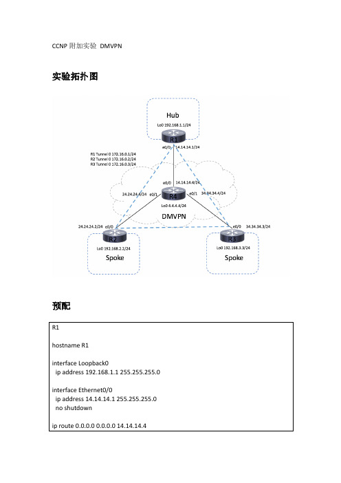
CCNP附加实验 DMVPN实验拓扑图预配R1hostname R1interface L oopback0ip a ddress 192.168.1.1 255.255.255.0interface E thernet0/0ip a ddress 14.14.14.1 255.255.255.0no s hutdownip r oute 0.0.0.0 0.0.0.0 14.14.14.4R2hostname R2interface L oopback0ip a ddress 192.168.2.2 255.255.255.0interface E thernet0/0ip a ddress 24.24.24.2 255.255.255.0 no s hutdownip r oute 0.0.0.0 0.0.0.0 24.24.24.4R3hostname R3interface L oopback0ip a ddress 192.168.3.3 255.255.255.0interface E thernet0/0ip a ddress 34.34.34.3 255.255.255.0 no s hutdownip r oute 0.0.0.0 0.0.0.0 34.34.34.4R4hostname R4interface L oopback0ip a ddress 4.4.4.4 255.255.255.0interface E thernet0/0ip a ddress 14.14.14.4 255.255.255.0 no s hutdowninterface E thernet0/1ip a ddress 24.24.24.4 255.255.255.0 no s hutdowninterface E thernet0/2ip a ddress 34.34.34.4 255.255.255.0no s hutdown实验目标1. 通过NHRP的方式实现mGRE互联,R1为NHRP的服务端,network-‐id:123,验证口令为HACCNP,GRE隧道的验证key为9992. 在R1,R2,R3上运行EIGRP路由协议,实验Hub和Spoke间环回口互通3. 实现Spoke-‐Spoke间的最优路由互联4. 优化隧道接口的MTU和MSS分别为1400和13605. Hub和Spoke同时能够通过PAT转换访问互联网(4.4.4.4)配置步骤1R1(config)#interface T unnel0R1(config-‐if)# i p a ddress 172.16.0.1 255.255.255.0R1(config-‐if)# i p n hrp a uthentication H ACCNPR1(config-‐if)# i p n hrp m ap m ulticast d ynamicR1(config-‐if)# i p n hrp n etwork-‐id 123R1(config-‐if)# t unnel s ource E thernet0/0R1(config-‐if)# t unnel m ode g re m ultipointR1(config-‐if)# t unnel k ey 999R2(config)#interface T unnel0R2(config-‐if)# i p a ddress 172.16.0.2 255.255.255.0R2(config-‐if)# i p n hrp a uthentication H ACCNPR2(config-‐if)# i p n hrp m ap 172.16.0.1 14.14.14.1R2(config-‐if)# i p n hrp m ap m ulticast 14.14.14.1R2(config-‐if)# i p n hrp n etwork-‐id 123R2(config-‐if)# i p n hrp n hs 172.16.0.1R2(config-‐if)# t unnel s ource E thernet0/0R2(config-‐if)# t unnel m ode g re m ultipointR2(config-‐if)# t unnel k ey 999R3(config)#interface T unnel0R3(config-‐if)# i p a ddress 172.16.0.3 255.255.255.0R3(config-‐if)# i p n hrp a uthentication H ACCNPR3(config-‐if)# i p n hrp m ap 172.16.0.1 14.14.14.1R3(config-‐if)# i p n hrp m ap m ulticast 14.14.14.1R3(config-‐if)# i p n hrp n etwork-‐id 123R3(config-‐if)# i p n hrp n hs 172.16.0.1R3(config-‐if)# t unnel s ource E thernet0/0R3(config-‐if)# t unnel m ode g re m ultipointR3(config-‐if)# t unnel k ey 999验证在R1,R2,R3分别ping 对方tunnle接口IP是正常的,说明NHRP工作正常 R1#ping 172.16.0.1!!!!!R1#ping 172.16.0.2!!!!!R1#ping 172.16.0.3!!!!!R1#sh i p n hrp172.16.0.1/32Tunnel0 c reated 00:02:58, e xpire 00:00:06Type: i ncomplete, F lags: n egativeCache h its: 2172.16.0.2/32 v ia 172.16.0.2Tunnel0 c reated 00:03:08, e xpire 01:57:19Type: d ynamic, F lags: u nique r egistered u sed n hopNBMA a ddress: 24.24.24.2172.16.0.3/32 v ia 172.16.0.3Tunnel0 c reated 00:00:51, e xpire 01:59:32Type: d ynamic, F lags: u nique r egistered u sed n hopNBMA a ddress: 34.34.34.3步骤2在R1,R2,R3上开启EIGRP路由协议,开启对应的隧道接口和lookback接口 R1(config)#router e igrp 1R1(config-‐router)#network 172.16.0.0 0.0.0.255R1(config-‐router)#network 192.168.1.0R2(config)#router e igrp 1R2(config-‐router)#network 172.16.0.0 0.0.0.255R2(config-‐router)#network 172.16.0.0 0.0.0.25R3(config)#router e igrp 1R3(config-‐router)#network 172.16.0.0 0.0.0.255R3(config-‐router)#network 192.168.3.0 0.0.0.255验证看到R1上学到spoke端的192.168.1.0/24和192.168.2.0/24路由,但是Spoke端R2和R3只学到192.168.1.0/24,而没有学到spoke另一端的路由R1#sh i p r oute e igrpD 192.168.2.0/24 [90/27008000] v ia 172.16.0.2, 00:00:34, T unnel0D 192.168.3.0/24 [90/27008000] v ia 172.16.0.3, 00:04:00, T unnel0R2#sh i p r oute e igrpD 192.168.1.0/24 [90/27008000] v ia 172.16.0.1, 00:05:06, T unnel0R3#sh i p r oute e igrpD 192.168.1.0/24 [90/27008000] v ia 172.16.0.1, 00:05:03, T unnel0步骤3在Hub端R1上得tunnle接口下关闭split-‐horizon让spoke学到spoke的路由,关闭next-‐hop-‐self,让路由可以之间spoke到spoke,而不必次优走HubR1(config)#int t unnel 0R1(config-‐if)#no i p s plit-‐horizon e igrp 1R1(config-‐if)#no i p n ext-‐hop-‐self e igrp 1验证R2#sh i p r oute e igrpD 192.168.1.0/24 [90/27008000] v ia 172.16.0.1, 00:23:02, T unnel0D 192.168.3.0/24 [90/28288000] v ia 172.16.0.3, 00:23:01, T unnel0R3#sh i p r oute e igrpD 192.168.1.0/24 [90/27008000] v ia 172.16.0.1, 00:13:41, T unnel0D 192.168.2.0/24 [90/28288000] v ia 172.16.0.2, 00:13:41, T unnel0R1#ping 192.168.2.2 s ource l oopback 0!!!!!R1#ping 192.168.3.3 s ource l oopback 0!!!!!R2#ping 192.168.1.1 s ource l oopback 0!!!!!R2#ping 192.168.3.3 s ource l oopback 0!!!!!R2#traceroute 192.168.3.3 s ource l oopback 01 172.16.0.3 3 m sec2 m sec *R3#ping 192.168.1.1 s ource l oopback 0!!!!!R3#ping 192.168.2.2 s ource l oopback 0!!!!!R3#traceroute 192.168.2.2 s ource l oopback 01 172.16.0.2 2 m sec 7 m sec *步骤4R1(config)#interface T unnel0R1(config-‐if)# i p m tu 1400R1(config-‐if)# i p t cp a djust-‐mss 1360R2(config)#interface T unnel0R2(config-‐if)# i p m tu 1400R2(config-‐if)# i p t cp a djust-‐mss 1360R3(config)#interface T unnel0R3(config-‐if)# i p m tu 1400R3(config-‐if)# i p t cp a djust-‐mss 1360步骤5R1(config)#access-‐list 1 p ermit 192.168.1.0 0.0.0.255R1(config)#ip n at i nside s ource l ist 1 i nterface e0/0 o verload R1(config)#int l ookback0R1(config-‐if)#ip n at i nsideR1(config-‐if)#int e0/0R1(config-‐if)#ip n at o utsideR2(config)#access-‐list 1 p ermit 192.168.2.0 0.0.0.255R2(config)#ip n at i nside s ource l ist 1 i nterface e0/0 o verloadR2(config)#int l ookback0R2(config-‐if)#ip n at i nsideR2(config-‐if)#int e0/0R2(config-‐if)#ip n at o utsideR3(config)#access-‐list 1 p ermit 192.168.3.0 0.0.0.255R3(config)#ip n at i nside s ource l ist 1 i nterface e0/0 o verloadR3(config)#int l ookback0R3(config-‐if)#ip n at i nsideR3(config-‐if)#int e0/0R3(config-‐if)#ip n at o utside验证R1#ping 4.4.4.4 s ource l oopback 0!!!!!R1#sh i p n at t ranslationsPro I nside g lobal Inside l ocal Outside l ocal Outside g lobal icmp 14.14.14.1:17 192.168.1.1:17 4.4.4.4:17 4.4.4.4:17R2#ping 4.4.4.4 s ource l oopback 0!!!!!R2#sh i p n at t ranslationsPro I nside g lobal Inside l ocal Outside l ocal Outside g lobal icmp 24.24.24.2:7 192.168.2.2:7 4.4.4.4:7 4.4.4.4:7R3#ping 4.4.4.4 s ource l oopback 0!!!!!R3#sh i p n at t ranslationsPro I nside g lobal Inside l ocal Outside l ocal Outside g lobal icmp 34.34.34.3:2 192.168.3.3:2 4.4.4.4:2 4.4.4.4:2。
- 1、下载文档前请自行甄别文档内容的完整性,平台不提供额外的编辑、内容补充、找答案等附加服务。
- 2、"仅部分预览"的文档,不可在线预览部分如存在完整性等问题,可反馈申请退款(可完整预览的文档不适用该条件!)。
- 3、如文档侵犯您的权益,请联系客服反馈,我们会尽快为您处理(人工客服工作时间:9:00-18:30)。
EBGP
1.1.1.0/24
R6
IBGP
3.3.3.0/24
IBGP R1 IBGP AS 100 EBGP AS 200
R3
33.33.33.0/24
要求: 1.在R2上通过分发列表将10.0.2.0/25网段过滤,但能够看到10.0.2.0/26。 2.在AS200中观察到1.1.1.0/24 、10.0.2.0/26 、10.0.3.0/26 、10.0.1.0/25 、 10.0.1.0/24、10.0.2.128/25。 3.R2-R3-R6之间运行eigrp。但12.12.12.0网段不在eigrp中宣告。 提示:此综合实验只找到一处关键点无法出现效果。顾多看看要求和整体配置文件。
R3
192.168.1.0/24 192.168.2.0/24
要求: 1、全网互通。 2、路由表中条目最少。
OSPF
Area 0 RIPv2 11.1.1.1/24 11.1.2.1/24 11.1.3.1/24 11.1.4.1/24
16.16.16.0/24
Area 4 Area 3 S0/3
EIGRP
EIGRP RIP
172.16.1.0/24 172.16.2.0/24 172.16.3.0/24 . . . 172.16.10.0/24 S0/3
R2
16.16.16.0/24 26.26.26.0/24 S0/2
R1
S0/1
S0/1 R6
S0/3 36.36.36.0/24 S0/3
36.36.36.0/24 S0/3
30.30.30.0/24
R1
E1/1
E1/1
R6
S0/2 26.26.26.0/24
Area 0
R2
20.20.20.0/24
Area 2 S0/2
要求: 1、四台路由器全部运行OSPF 协议; 2、将外部网络重分发进入OSPF内部,并保证最少的路由条目。 3、阻止网络20.20.20.0/24进入R3的内部网络; 4、R2和R6之间进行MD5认证; 5、要求全网互通,共13条路由。
RIP
S0/3 30.30.30.0/24
R3
16.16.16.0/24 10.10.10.0/24 36.36.36.0/24 S0/3
R1
S0/1
S0/1
R6
S0/2 26.26.26.0/24 S0/2
60.60.60.0/24
R2
20.20.20.0/24
要求: 1、四台路由器全部运行RIP协议; 2、阻止网络30.30.30.0/24进入R1的内部网络; 3、R2和R6之间封装帧中继协议。 4、R3和R6之间进行MD5认证; 5、全网络共11条路由。
R1
R6
S0/0 26.26.26.6/24 FR S0/0 26.26.26.2/324
R2
20.20.20.2/24
Loopback0 2.2.2.2/32 10.10.10.1/24 60.60.60.6/24
1、R1和R6之间PPP。 2、R1到R6是chap认证,R6到R1是PAP认证。 3、R2和R6之间帧中继,且关闭动态映射。 4、R3和R6之间HDLC。 5、R1,R6,R2,R3配置EIGRP协议,且路由表收敛,均有11条路由条目。
串行链路
Loopback0 6.6.6.6/32 Loopback0 1.1.1.1/32
HDLC
S0/1 16.16.16.1/24 S0/1 16.16.16.6/24
Loopback0 3.3.3.3/32
S0/3 36.36.36.3/24 S0/3 36.36.36.6/24
PPP
R3
30.30.30.3/24
BGP邻接关系
BGP邻居关系
EBGP 1.1.1.0/24
R6 IBGP
3.3.3.0/24
R3 R1 AS 100 R2 EBGP AS 200
IBGP
33.33.33.0/24
要求: 1.R1-R6 R6-R3通过环回口建立邻接关系。 2.R2-R3-R6运行eigrp。
BGP路由安装
BGP邻居关系
