Sigrist在线浊度计 TurBiScat 中文参考手册
TurbiScat中文操作手册
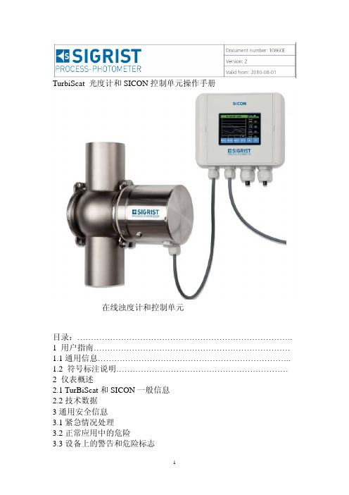
TurbiScat 光度计和SICON控制单元操作手册在线浊度计和控制单元目录:…………………………………………………………………….1 用户指南………………………………………………………………1.1通用信息……………………………………………………………..1.2 符号标注说明………………………………………………………2 仪表概述2.1 TurBiScat和SICON一般信息2.2技术数据3通用安全信息3.1紧急情况处理3.2正常应用中的危险3.3设备上的警告和危险标志4机械安装4.1光度计的安装4.2 SICON控制单元的墙装方法5电气安装5.1电气安装的一般步骤5.2 标准版本的SICON的安装5.3 Profibus、Modbus、fieldbus接口的连接6初次试车运行7运行操作7.1 基本的操作原则7.2 正常显示模式7.3转换到服务模式7.4 操作语言设置1 用户指南1. 1.通用信息这个指导手册的用途:这本指导手册提供的信息指导用户在仪表的整个生命周期里的维护和使用。
用户必须在仪表投运之前需阅读此手册。
指导手册的使用对象:这本手册适用于所以可能操作和维护这个仪表的人员。
更多的资料:手册代号 题目 内容10862E 快速参考手册 主要功能和完整的菜单结构10861E 参考手册 扩展菜单功能和熟练用户的附加信息10863E 服务手册 用于专业服务人员维修和更换备件10905DEF 资质声明 仪表遵从的标准和原则声明版权说明:本手册由SIGRIST-PHOTOMETER AG编写,只可以拷贝,更改或传给其他第三方都需要SIGRIST-PHOTOMETER AG的书面认可。
手册的保管:这个操作手册是产品的一部分,要保证随时处于可用状态,注册用户可以从网站下载最新版本,另外也可以从本国有资质的代理商那里购买。
1.2. 标志符号解释危险标志:包含在此手册中的所有危险标志如下:所有可能造成严重触电伤害或死亡的危险标志。
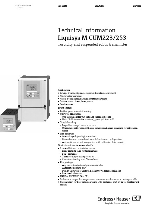
Liquisys M CUM223 253 浊度和悬浮粒子传感器应用手册说明书
Products Solutions Services TI00200C/07/EN/14.1371235717Technical InformationLiquisys M CUM223/253Turbidity and suspended solids transmitterApplication•Sewage treatment plants, suspended solids measurement•Wastewater treatment•Water treatment and drinking water monitoring•Surface water: rivers, lakes, ocean•Service waterYour benefits•Field or panel-mounted housing•Universal application–One instrument for turbidity and suspended solids–Units: FNU (formazine standard), ppm, g/l, % or % SS•Simple handling–Logically arranged menu structure–Ultrasimple calibration with user samples and alarm signalling for calibrationerrors•Safe operation–Overvoltage (lightning) protection–Manual contact control and user-defined alarm configuration–Automatic sensor self-recognition with calibration data transferThe basic unit can be extended with:•2 or 4 additional contacts for use as:–Limit contacts (also for temperature)–P(ID) controller–Timer for simple rinse processes–Complete cleaning with Chemoclean•Plus package:–Any current output configuration via table–Automatic cleaning start–Display in customer units (e.g. density) via table assignment–Live check of sensor•HART or PROFIBUS PA / DP•2nd current output for temperature, main measured value or actuating variable•Current input for flow rate monitoring with controller shut off or for feedforwardcontrolLiquisys M CUM223/2532Endress+HauserFunction and system designFeatures of the basic versionMeasurement of turbidity and suspended solidsThe sensor is selected from the menu. During measurement, the value measured can be displayed in the other measuring mode. The temperature is displayed at the same time if desired.ConfigurationDifferent alarms are required depending on application and operator. Therefore the transmitterpermits independent configuration of the alarm contact and error current for each individual error. Unnecessary or undesirable alarms can be suppressed in this manner. Up to four contacts Up to two contacts can be used as limit contacts (also for temperature), to implement a P(ID) controller or for cleaning functions.Direct manual operation of the contacts (bypassing the menu) provides quick access to limit, control or cleaning contacts, permitting speedy correction of deviations.The serial numbers of the instrument and modules and the order code can be called up on the display.Additional functions of the Plus package TSCurrent output configurationIn order to output wide measuring ranges while still achieving a high resolution in specific ranges, the current output can be configured as required via a table. This permits bilinear or quasi-logarithmic curves, etc.Process Check System (PCS)It comprises two independent safety functions:•Errors in applications without control are detected by monitoring the limit between plausible and implausible measured values, i.e. the alarm threshold .•Errors in applications with control are detected by the controller monitor which monitors freely adjustable, maximum permissible time intervals and reference value overshoot or undershoot.Live checkThe live check issues an alarm when the sensor signal does not change over a defined period of time. This may be caused by blocking, passivation, separation from the process, etc.Additional functions of version TSDisplay of various measurement unitsIn addition to turbidity (FNU, NTU) and concentration (ppm / % SS), the display can also show other units (e.g. density). A table is used for conversion (calibration in %).Second current outputThe second current output can be configured for temperature, main measured value (turbidity, suspended solids) or actuating variable.Current inputThe current input of the transmitter allows two different applications: controller shut-down in case of lower flow rate violation or total failure in the main flow as well as feedforward control. Both functions are also combinable.Liquisys M CUM223/253Endress+Hauser 3Measuring systemA complete measuring systems comprises:•The transmitter Liquisys M CUM223 or CUM253•A sensor with or without an integrated temperature sensor •An immersion, flow or retractable assemblyOptions: extension cable CYK81, junction box VBM or RM123Immersion assembly CYA611Retractable assembly CUA451Assembly with gas bubble trap45Liquisys CUM253Liquisys CUM223Liquisys M CUM223/2534Endress+HauserInputMeasured variables Turbidity, suspended solids, temperature Measuring rangeCable specificationSignal inputDigital communication Temperature measurement NTC 30 k Ω at 25 °C (77 °F)Binary inputsCurrent input4to 20mA, galvanically separated Load: 260Ω at 20mA (voltage drop 5.2V)CUS31:0.000 to 9999 FNU/NTU 0.00 to 3000 ppm 0.0 to 3.0 g/l 0.0 to 200.0 %CUS41:0.00 to 9999 FNU/NTU 0.00 to 9999 ppm 0.0 to 300.0 g/l 0.0 to 200.0 %Temperature:-5.0 to +70.0 °C (+23 to +158 °F)Cable length:max. 200 m (656 ft.)Voltage:10to 50V Power consumption:max. 10mALiquisys M CUM223/253Endress+Hauser 5OutputOutput signal0/4 to 20 mA, galvanically separated, activeSignal on alarm 2.4 or 22 mA in case of an error Loadmaximum 500 Ω Transmission rangeResolution max. 700 digits/mA Isolation voltage max. 350 V RMS /500 V DC Overvoltage protection according to EN 61000-4-5Auxiliary voltage outputContact outputsLimit contactorHART Signal coding Frequency Shift Keying (FSK) + 0.5 mA via current output signal Data transfer rate 1200 Baud Galvanic isolationyesPROFIBUS PA Signal coding Manchester Bus Powered (MBP)Data transfer rate 31.25 kBit/s, voltage mode Galvanic isolationyes (IO-Module)PROFIBUS DP Signal coding RS485Data transfer rate 9.6 kBd, 19.2 kBd, 93.75 kBd, 187.5 kBd, 500 kBd, 1.5 MBd Galvanic isolationyes (IO-Module)CUS31/CUS41:adjustable, min. ∆ 0.1 FNU, ∆ 0.1 ppm, ∆ 0.1 g/l, ∆ 0.1 %Temperature:adjustable, ∆ 10to ∆ 100 % of measuring rangeOutput voltage:15V ± 0.6Output current:max. 10mA Switching current with ohmic load (cos ϕ= 1):max. 2A Switching current with inductive load (cos ϕ = 0.4):max. 2ASwitching voltage:max. 250V AC, 30V DC Switching power with ohmic load (cos ϕ = 1):max. 500 VA AC, 60W DC Switching power with inductive load (cos ϕ = 0.4):max. 500VA AC, 60W DC Pickup/dropout delay:0to 2000sLiquisys M CUM223/2536Endress+HauserControllerAlarmFunction (adjustable):pulse length/pulse frequency controller Controller response:PIDControl gain K p :0.01to 20.00Integral action time T n :0.0to 999.9min Derivative action time T v :0.0to 999.9min Period for pulse length controller:0.5to 999.9 s Frequency for pulse frequency controller:60to 180 min -1Basic load:0to 40% of max. set valueFunction (selectable):Latching /momentary contactAlarm threshold adjustment range:Turbidity / suspended solids / temperature: complete measuring range Alarm delay:0to 2000s 0 to 2000 minLiquisys M CUM223/253Protocol specific data HARTManufacturer ID11hDevice type code0095hTransmitter specific revision0001hHART specification 5.0DD files /hartLoad HART250Device variables None (dynamic variables PV, SV, only)Features supported-PROFIBUS PAManufacturer ID11hIdent number1517hDevice revision11hProfile version 2.0GSD files /profibusGSD file versionOutput values Main value, temperature valueInput values Display value of PLCFeatures supported Device locking: The device can be locked by hardware orsoftware.PROFIBUS DPManufacturer ID11hIdent number151F hProfile version 2.0GSD files /profibusGSD file versionOutput values Main value, temperature valueInput values Display value of PLCFeatures supported Device locking: The device can be locked by hardware orsoftware.Endress+Hauser7Liquisys M CUM223/2538Endress+HauserPower supplyElectrical connectionThe device is approved for protection class II and is generally operated without a protective ground connection.The circuits "C" and "F" are not galvanically isolated from each other.Electrical connection of the transmitterA B C DE F G SensorSignal output 1 turbidity/solids content Signal output 2 temperature Binary input 1 (Hold)Binary input 2 (Chemoclean)Aux. voltage outputAlarm (current-free contact position)H I J K L M Relay 1 (current-free contact position)Relay 2 (current-free contact position)Relay 3 (current-free contact position)Relay 4 (current-free contact position)Current input 4to 20mA Power supplyLiquisys M CUM223/253Endress+Hauser 9Sensor cableThe sensors are delivered with measuring cables. Use a junction box and an extension cable to extend the measuring cable (see "Accessories")Connection of the turbidity sensors CUS31 and CUS41Supply voltageDepending on ordered version:100/115/230 V AC +10/-15 %, 48 to 62 Hz 24 V AC/DC +20/-15 %Fieldbus connectionHART Supply voltagen/a, active current outputs Integrated reverse voltage protectionn/a, active current outputsPROFIBUS PA Supply voltage 9 V to 32 V, max. 35 V Polarity sensitiveno FISCO/FNICO compliant acc. to IEC 60079-27noPROFIBUS DP Supply voltage 9 V to 32 V, max. 35 V Polarity sensitiven/a FISCO/FNICO compliant acc. to IEC 60079-27noLiquisys M CUM223/25310Endress+HauserPower consumption max. 7.5 VAMains protection Fine-wire fuse, medium-slow blow 250 V/3.15 ACircuit breakerThe device does not have a power switch‣You must provide a protected circuit breaker in the vicinity of the device.‣This must be a switch or a power-circuit breaker and you must label it as the circuit breaker for thedevice.‣At the supply point, the power supply for the 24 V versions must be isolated from dangerous livecables by double or reinforced insulation.Performance characteristicsMeasured value resolutionMaximum measured error 1)Repeatability 2)± 1% of measured value (min. 0.01 FNU)CUS31:0.001 FNU/NTU, 0.01 ppm, 0.01 g/l, 0.01 %CUS41:0.01 FNU/NTU, 0.01 ppm, 0.01 g/l, 0.01 %Temperature:0.1 °C1) acc. to IEC 746-1, for nominal operating conditions DisplayCUS31/CUS41:± 2 % of measured value (min. 0.02 FNU)Temperature:max. 1.0% of measuring rangeSignal outputCUS31/CUS41:1% of current output range (min. 0.02 FNU)Temperature:max. 1.25% of current output range2) acc. to IEC 746-1, for nominal operating conditionsLiquisys M CUM223/253Endress+Hauser11InstallationInstallation instructionsField instrumentMounting on pipes 1 - 3Mounting screws and mounting plateLiquisys M CUM223/25312Endress+HauserView into the field instrument1234Removable electronics box Partition plate Terminal blocks FuseWall mounting of the field instrument 1Mounting holes 2 Protecting capMounting of the field instrument with mounting post and weather protection cover 1 - 3Mounting holesØ6/Ø0.24Liquisys M CUM223/253Endress+Hauser 13Dimensions panel-mounted instrumentInstallation of the panel-mounted instrument 1Wall of control cabinet 2Gasket 3Tensioning screws*Required installation depth92/ 3.62+0.5+0.0292/ 3.62+0.5+0.02Liquisys M CUM223/25314Endress+HauserEnvironmentAmbient temperature -10 to +55 °C (+14 to +131 °F)Storage temperature –25 to +65 °C (-13 to +149 °F)Electromagnetic compatibility Interference emission and interference immunity as per EN 61326-1:2006, EN 61326-2-3:2006Ingress protectionElectrical safety according EN/IEC 61010-1:2001, Installation Category II, for use up to 2000 m above sea level CSAApparatus with CSA General Purpose Approval are certified for indoor use.Relative humidity 10 to 95%, non-condensingPollution degreeThe product is suitable for pollution degree 2.Mechanical constructionDimensionsWeightMaterialTerminalsPanel mounted instrument:IP 54 (front), IP 30 (housing)Field instrument:IP 65 / tightness acc. to NEMA 4XPanel-mounted instrument:96x 96x 145mm (3.78 x 3.78 x 5.71 inches)Installation depth: approx. 165mm (6.50")Field instrument:247x 170x 115mm (9.72 x 6.69 x 4.53 inches)Panel-mounted instrument:max. 0.7kg (1.5 lb)Field instrument:max.2.3kg (5.1 lb)Housing of panel-mounted instrument:Polycarbonate Field housing:ABS PC FrFront membrane:Polyester, UV-resistant Cross sectionmax. 2.5 mm 2 (14 AWG)Liquisys M CUM223/253Endress+Hauser 15OperabilityOperating conceptAll instrument control functions are arranged in a logical menu structure. Following access code entry, the individual parameters can be easily selected and modified as needed.Display elementsOperating elements 1LC display for displaying the measured values and configuration data 2Field for user labelling3 4 main operating keys for calibration and device configuration 4Changeover switch for automatic/manual mode of the relays 5LEDs for limit contactor relay (switch status)6LED for alarm function7Display of the active contact and key for relay changeover in manual modeCertificates and approvals4 symbolDeclaration of conformityThe product meets the requirements of the harmonized European standards. It thus complies with the legal requirements of the EC directives.The manufacturer confirms successful testing of the product by affixing the 4 symbol.CSA General PurposeCSA General PurposeThe products listed below are eligible to bear the CSA Mark shown with adjacent indicators "C" and "US":Version ApprovalCUM253-..2...CUM253-..3...CUM253-..7...CSA Mark for Canada and USACUM223-..2...CUM223-..3...CUM223-..7...CSA Mark for Canada and USALiquisys M CUM223/25316Endress+HauserOrdering informationOrder codeEnter the following address into your browser to access the relevant product page:/cum223 or /cum2531.2.Click "Configure this product".3.The configurator opens in a separate window. You can now configure your device and receive the complete order code that applies for the device.4.Afterwards, export the order code as a PDF or Excel file. To do so, click the appropriate button at the top of the page.Product structureAdditional functions of the Plus package•Current output table to cover wide ranges with varying resolution, fields O33x •Process Check System (PCS): live check of the sensor, function group P •Concentration measurement, function group K •Automatic cleaning function start, field F8Input, software versionTB Suspended solids with factory setup > residual concrete water TU Turbidity and suspended solids measurementTSTurbidity and suspended solids measurement, with additional functions (Plus package)Power supply; approval0230V AC 1115V AC2230V AC; CSA Gen. Purp.3115V AC; CSA Gen. Purp.5100V AC724V AC/DC; CSA Gen. Purp.824V AC/DCOutput0 1 x 20 mA, primary value1 2 x 20 mA, primary value + secondary value 3PROFIBUS PA 4PROFIBUS DP5 1 x 20 mA, primary value, HART62 x 20 mA, primary value, HART + secondary valueAdditional contacts05not selected10 2 relays (limit/P(ID)/timer)15 4 relays (limit/P(ID)/Chemoclean) (not with PROFIBUS DP)16 4 relays (limit/P(ID)/timer) (not with PROFIBUS DP)20 1 x 4 to 20 mA input + 2 relays (limit/P(ID)/timer)25 1 x 4 to 20 mA input + 4 relays (limit/P(ID)/Chemoclean) (not with PROFIBUS DP)261 x 4 to 20 mA input + 4 relays (limit/P(ID)/timer) (not with PROFIBUS DP)Marking1Tagging (Tag), see additional spec.CUM253-complete order codeCUM223-Liquisys M CUM223/253Endress+Hauser 17Scope of deliveryThe delivery of the field instrument includes:•1 transmitter CUM253•1 plug-in screw terminal •1 cable gland Pg 7•1 cable gland Pg 16 reduced •2 cable glands Pg 13.5 •1 Operating Instructions•1 Operating Instructions BA00200C/07/EN •versions with HART communication:1 Operating Instructions Field Communication with HART, BA00208C/07/EN •versions with PROFIBUS communication:1 Operating Instructions Field Communication with PROFIBUS PA/DP, BA00209C/07/EN The delivery of the panel-mounted instrument includes:•1 transmitter CUM223•1 set of plug-in screw terminals •2 tensioning screws •1 Operating Instructions•1 Operating Instructions BA00200C/07/EN •versions with HART communication:1 Operating Instructions Field Communication with HART, BA00208C/07/EN •versions with PROFIBUS communication:1 Operating Instructions Field Communication with PROFIBUS PA/DP, BA00209C/07/ENLiquisys M CUM223/25318Endress+HauserAccessoriesSensorsTurbimax W CUS31•Turbidity sensor for drinking water and wastewater applications, 90 ° scattered light method •Ordering acc. to product structure, see Technical Information (TI176C/07/en)Turbimax W CUS41•Turbidity sensor for wastewater and solid content measurements, 90 ° scattered light method •Ordering acc. to product structure, see Technical Information (TI177C/07/en)Connection accessoriesCYK81 measuring cable•Non-terminated cable for extending the sensor cables (e.g. Memosens)•2x2 wires, twisted with shield and PVC sheath (2x 2x 0.5 mm 2 + shield)•Goods sold by meter, order no.: 51502543Junction box RM•For cable extension (e.g. for Memosens sensors)•5 terminals•Cable entries: 2 x Pg 13.5•Material: PC•Ingress protection: IP 65•Order no.: 51500832Mounting accessoriesCYY101 weather protection cover for field devices, absolutely essential if operating the unit outdoors •Material: stainless steel 1.4031 (AISI 304)•Order No. CYY101-AWeather protection cover for field devicesLiquisys M CUM223/253Endress+Hauser 19Post mounting kit•For mounting of field housing on horizontal or vertical pipes (Ø max. 60 mm (2.36"))•Material: stainless steel 1.4301•order no. 50086842Post mounting kitCYY102 universal post•Square pipe for mounting transmitters •Material: stainless steel 1.4301 (AISI 304)•Order No. CYY102-AUniversal post。
杭州联测自动化技术有限公司 U-SIN-PTU110-MYCN2 第2版 浊度在线分析仪 使用说明书

杭州联测自动化技术有限公司 服务电话:400-185-1718更多资讯请扫二维码杭州联测自动化技术有限公司U-S IN -PTU 110-MY CN 2第2版浊度在线分析仪使用说明书前言●感谢您购买本公司产品。
●本手册是关于产品的各项功能、接线方法、设置方法、操作方法、故障处理方法等的说明书。
●在操作之前请仔细阅读本手册,正确使用本产品,避免由于错误操作造成不必要的损失。
●在您阅读完后,请妥善保管在便于随时取阅的地方,以便操作时参照。
注意●本手册内容如因功能升级等有修改时,恕不通知。
●本手册内容我们力求正确无误,如果您发现有误,请与我们联系。
●本手册内容严禁转载、复制。
●本产品禁止使用在防爆场合。
版本U-S IN-PTU110-MYCN2第二版2021年4月安全注意事项为了安全使用本产品,操作时请务必遵守此处描述的安全注意事项。
关于本手册●请将本手册交于操作者阅读。
●在操作之前,请熟读本手册,并对产品有深入了解。
●本手册只对产品的功能进行阐述,本公司不保证该产品将适合于用户的某一特殊用途。
本产品保护,安全及改造相关注意事项●为了确保安全使用本产品以及由其控制的系统,操作时请务必遵守本手册中所述说明和注意事项。
如果违反操作规程,则有可能会损坏本产品所提供的保护功能。
对由以上情况产生的质量、性能、功能和产品的安全问题,本公司不承担任何责任。
●为本产品及其控制系统安装防雷装置,或为本产品及其控制系统设计安装单独的安全保护电路时,需要借助其他的设备来实现。
●如果需要更换产品的零部件,请使用本公司指定的型号规格。
●本产品不适用于直接关系到人身安全的系统。
如核动力设备、使用放射能的设备、铁路系统、航空机器、船舶用设备、航空设备和医疗器械等。
如果应用,用户有责任使用额外的设备或系统确保人身安全。
●请勿改造本产品。
在本手册中使用以下几种安全标志:危险标志,若不采取适当的预防措施,将导致严重的人身伤害、仪表损坏或重大财产损失等事故。
在线浊度计说明书

在线浊度测量仪使用说明书型号:OMN-SS无锡沃曼尼科技有限公司一、产品概述本公司2013年全新面世的一款自主研发的全中文操作界面的中文在线浊度计,采用世界先进微处理器,大规模STM技术,国际先进的光路设计,使仪器测量范围更宽、精准度更高、更符合国内复杂环境下在水工业处理工艺过程中提供准确的浊度数值而设计的新一代在线水质分析仪器。
二、测量原理采用红外光散射135℃和90℃双光路测量原理。
光源采用世界先进的LED光源,具有测量准确、测量范围大、性能稳定、使用寿命长的优点。
三、技术参数测量范围:0~5NTU 5~50NTU 50~500NTU 500~5000NTU0~15mg/L ,15~150mg/L ,150~1500mg/L ,1500~15000mg/L 重复性: ≤1.5%;测量精度: ±2%;稳定性:1.5%零点漂移:1.5%流速范围:0.3-3m/s信号输出:模拟4~20mA或数字RS485通讯温度范围:-20℃~55℃供电电源:AC220V或DC24V频率: 50±1Hz;继电器输出:1路4~20mA电流信号隔离输出,最大负载750欧姆;2个报警信号继电器,容量220V AC/2A,输出可由用户1个冲洗时间继电器,容量220V AC/2A,时间可由用户设置。
测量单位:NTU、mg/L、ppm三种可选外壳材质:ABS防护等级:IP65第 1 页共8 页第 2 页 共 8 页重 量:2.5 kg四、应用场合◆ 市政、铁路、钢铁、化工、煤矿等生活用水; ◆ 污水处理厂 进水口、出水口等; ◆ 大专院校实验室水质检测;五、安装说明5.1、 变送器的安装5.1.1 在选择变送器安装位置时,需要遵循如下原则:◆ 特别注意避免变送器受阳光直射; ◆ 避免使变送器产生过多震动;◆ 如果情况允许,应将变送器安装于稍稍高于操作者平视水平的位置,这样将会有利于操作者非常舒服地浏览前部面板和进行控制操作; ◆ 为变送器箱体的开启和维护留出足够的空间,变送器尺寸。
浊度仪说明书
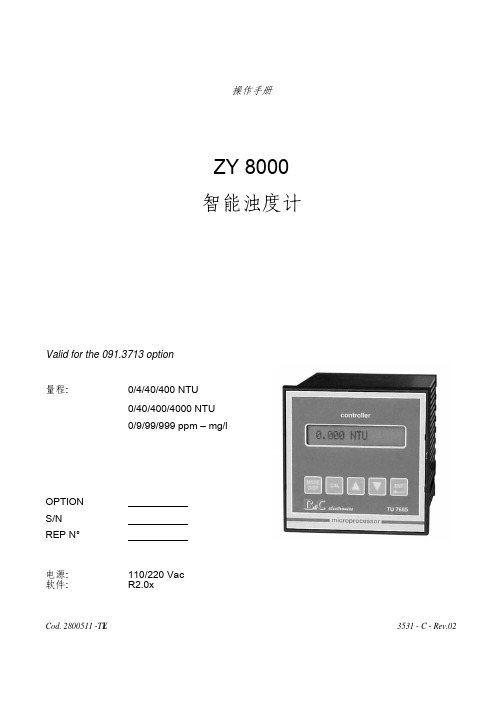
ZY 8000 智能浊度计
Valid for t0/4/40/400 NTU 0/40/400/4000 NTU 0/9/99/999 ppm – mg/l
OPTION S/N REP N°
电源: 软件:
110/220 Vac R2.0x
Cod. 2800511 -TLY
2 特点 ................................................................................................................................... 5
3 详述 ................................................................................................................................... 6 3.1 功能规格.................................................................................................................... 6 3.2 技术规格.................................................................................................................... 9 3.3 低浊度流通槽技术规格 ............................................................................................ 13 3.4 机械规格.................................................................................................................. 13
Sigrist 实验室浊度计 Labscat 2中文操作手册

② 带盖 USB 插口 ④ 盖子打开 ⑥ 盖子闭合 ⑧ 排水口(溢流/排空) ⑩ 调节阀/排空钮
8
2.2 Labscat 2 标识牌 仪表背面有如下标牌:
①
制造商
③
产品名称
⑤
生产日期
⑦
频率范围
⑨
操作指南
图 2: Labscat 2 标牌
②
原产地
④
序列号
⑥
供电电压
⑧
功率
⑩
报废处理
2.3 标准供货和随机配件 标准供货包括: 数量 订货号 名称
所遵循的各种标准的详细说明请参考 1.41 节
1.11 使用限制 ——————————————————————————— 在不适合的环境中运行的后果 如果在易爆环境中运行可能会引起爆炸,从而造成人身伤亡 ■ 禁止仪表在易爆危险环境或房间内运行。 ■ 禁止仪表用于检测具有易爆介质的样品。 ———————————————————————————
1.3 本手册适用人群 操作手册专为所有仪表操作与维护人员所准备。
1.4 其他附属资料
资料编号 12114E
12113E
12406E
题目 简明手册
参考手册
单页资料
T0006-13-303 sigrist DUALSCAT 在线啤酒浊度计校正操作标准书(试行)

按
11.
按
12.
按
键改变光标位置 键确认
键移动光标
〉Val.Adjust 25〈
1.83EBC!
-Meas90 -Meas25
1.86
1.72
13.
按 键移动光标
14.
按 键确认
15.
按 键移动光标
〉Adju〈 Retain Adju
〉 Retain 〈 Adju
〉 Adpat 〈
5-7
注: 如果此项设置,直接跳到第三步
输入实际数值:
按 7.
按
键改变数字 键改变光标位置
〉Val.Adjust90〈 0.00EBC!
8.
按 键确认
9.
按 键选择菜单
输入实际数值:
10. 按
键改变数值
〉Val.Adjust 90〈 1.83EBC!
〉Val.Adjust 90〈 0.00EBC!
〉Val.Adjust25〈 0.00EBC!
2-7
编号:T/0006-13-303 修订状态:0 修订日期:2011.01.18 SIGRIST DualScat 90/25 在线啤酒浊度计校正操作标准书(试行)
图 6-1 仪器面板(显示和按键)
图 6-2 7. 校正操作:
图 6-3
7.1 拆下浊度计:切断电源,在确保管道内无压力,无刷洗液等腐蚀性液体情况下排空管路,
编号:T/0006-13-303 修订状态:0 修订日期:2011.01.18 SIGRIST DualScat 90/25 在线啤酒浊度计校正操作标准书(试行)
批准: 单连菊 马 政
发布日期:2011.01.18
验证: 栾明昇 编写: 牟 钦
在线浊度计说明书

在线浊度测量仪使用说明书型号:OMN-SS无锡沃曼尼科技有限公司一、产品概述本公司2013年全新面世的一款自主研发的全中文操作界面的中文在线浊度计,采用世界先进微处理器,大规模STM技术,国际先进的光路设计,使仪器测量范围更宽、精准度更高、更符合国内复杂环境下在水工业处理工艺过程中提供准确的浊度数值而设计的新一代在线水质分析仪器。
二、测量原理采用红外光散射135℃和90℃双光路测量原理。
光源采用世界先进的LED光源,具有测量准确、测量范围大、性能稳定、使用寿命长的优点。
三、技术参数测量范围:0~5NTU 5~50NTU 50~500NTU 500~5000NTU0~15mg/L ,15~150mg/L ,150~1500mg/L ,1500~15000mg/L 重复性: ≤1.5%;测量精度: ±2%;稳定性:1.5%零点漂移:1.5%流速范围:0.3-3m/s信号输出:模拟4~20mA或数字RS485通讯温度范围:-20℃~55℃供电电源:AC220V或DC24V频率: 50±1Hz;继电器输出:1路4~20mA电流信号隔离输出,最大负载750欧姆;2个报警信号继电器,容量220V AC/2A,输出可由用户1个冲洗时间继电器,容量220V AC/2A,时间可由用户设置。
测量单位:NTU、mg/L、ppm三种可选外壳材质:ABS防护等级:IP65第 1 页共8 页第 2 页 共 8 页重 量:2.5 kg四、应用场合◆ 市政、铁路、钢铁、化工、煤矿等生活用水; ◆ 污水处理厂 进水口、出水口等; ◆ 大专院校实验室水质检测;五、安装说明5.1、 变送器的安装5.1.1 在选择变送器安装位置时,需要遵循如下原则:◆ 特别注意避免变送器受阳光直射; ◆ 避免使变送器产生过多震动;◆ 如果情况允许,应将变送器安装于稍稍高于操作者平视水平的位置,这样将会有利于操作者非常舒服地浏览前部面板和进行控制操作; ◆ 为变送器箱体的开启和维护留出足够的空间,变送器尺寸。
在线浊度仪中文简易操作说明

OUM223 Turbidity and Suspended Solids Transmitter
4
E
OUTPUT 0
-
ALARM F
5.4.1
8.4
F
ALARM
Stead F1 F1
Cont.Type
S F2 F2
Time Unit
1 F5 Sel.Error
22 mA F4 Err. Curr
1
1 1
FNU
100.0 C111
Concentr1
2
2 2
3
FNU
3
330.0 C112
Concentr2
yes
CAL
C115
Store
CAL
1.
2.
3.
4.
5.
1.
2. 1
3
9
3. 2 1
4.
3
3
2
33% 2
10% 1
1
33% 10%
2
>=1.1* 1
3
>=1.1* 2
1
3
Amer & Innovative Sensors In.
OUM223 Turbidity and Suspended Solids Transmitter
10.1
CAL Code
CAL
Code
22
CAL
CALIBRAT.
C
CAL
CALIBRAT.
o.k. C114 Status
3 CAL
56
3-Pt C1 Calibrat
1000.0
FNU C113
在线式浊度计的使用 浊度计如何操作

在线式浊度计的使用浊度计如何操作浊度计是用来测量浊度的一种检测仪器。
浊度计通过确定长度的样品发光,并检测水中粒子从入射光90°方向散射多少光。
这种测量散射光的方法称为浊度计适用于现浊度计是用来测量浊度的一种检测仪器。
浊度计通过确定长度的样品发光,并检测水中粒子从入射光90°方向散射多少光。
这种测量散射光的方法称为浊度计适用于现场和试验室测量以及全天连续监测。
浊度计可以设置为在测量的浊度值超过安全标按时发出警报。
在线浊度计是由于水中的悬浮颗粒,浮动颗粒反射入射光,但通常使用90度的散射光作为测量信号。
使用formazin标准溶液校准的设备测试的单位称为FNU。
该方法的范围为0.01至4000FNU,适用于中低程度测试。
依据EN27027和ISO7027标准,使用860nm的红外光作为光源,但这不受样品色度的影响。
在线浊度计的使用:1.假如有灰尘或污渍,请用吸取棉,乙醇擦拭。
可以用洗涤剂或洗涤剂清洗滤饼,然后用水冲洗,两个透亮表面都干燥。
工具加热10分钟。
2.选择性纤维的范围设置为“100”和涡轮机包机板(面对面左侧)直接插入样品槽后面。
3.推入掌控杆,确保光路上没有物体,调整“零”旋钮,使显示屏显示“0”(空气零点),拉出杆,将浊度精度板放入光路调整(调整)旋钮将显示屏显示为浊度标准板(NTU)的出厂校准值,之后“校准”旋钮无法任意更改,标准板被取出。
4.范围“1”;“10”使用30mm比色皿。
范围“100”使用5毫米比色皿。
在细胞旁边插入一个5mm比色皿。
将浑浊的水(约3/4高度)放入比色皿中,将其置于样品罐前面,测试液体进入样品罐后部(测量比色皿在右侧),按下棒。
按钮“零”“掌控部分”使计数器为0.拉出拉杆,样品放在光路中,显示的值是测得的液体浊度值NTU。
在测量中,选择按钮“”范围“要变化。
除了各种比色皿之外,调整水的浊度的步骤需要重复一次。
本仪器的标准PCB在出厂前用标准溶液校准。
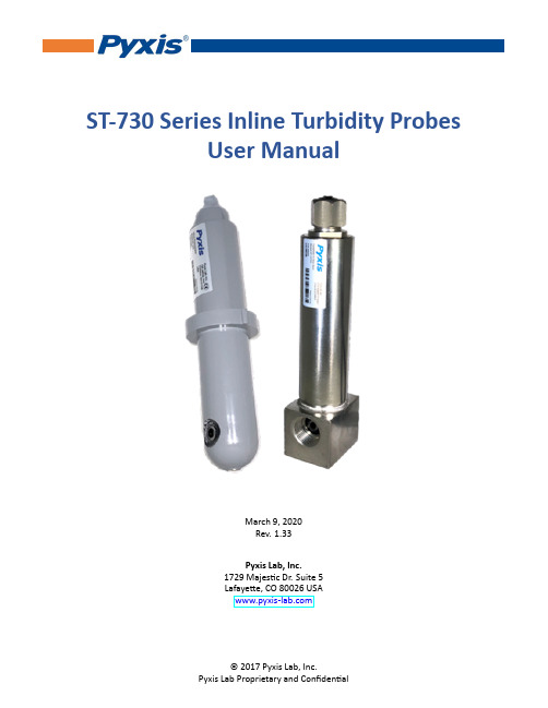
ST-730系列在线浊度探头用户手册说明书
ST-730Series Inline Turbidity ProbesUser ManualMarch9,2020Rev.1.33Pyxis Lab,Inc.1729Majestic Dr.Suite5Lafayette,CO80026USA©2017Pyxis Lab,Inc.Table of Contents1Introduction2 2Specifications2 3Unpacking Instrument23.1Standard Accessories (3)3.2Optional Accessories (3)4Installation44.1ST-730/730B/731/735Piping (4)4.2ST-730SS Piping (5)4.3Wiring (6)4.4Connecting via Bluetooth (6)4.5Connecting via USB (6)5Setup and Calibration with uPyxis®Mobile App75.1Download uPyxis®Mobile App (7)5.2Connecting to uPyxis®Mobile App (7)5.3Calibration Screen and Reading (8)5.4Diagnosis Screen (9)5.5Device Info Screen (9)6Setup and Calibration with uPyxis®Desktop App106.1Install uPyxis®Desktop App (10)6.2Connecting to uPyxis®Desktop App (10)6.3Information Screen (11)6.4Calibration Screen (11)6.5Diagnosis Screen (13)7Communication using Modbus RTU13 8Sensor Maintenance and Precaution138.1Methods to Cleaning ST-730Series Probe (14)8.2Storage (14)9Troubleshooting15 10Contact Us15Warranty InformationConfidentialityThe information contained in this manual may be confidential and proprietary and is the property of Pyxis Lab,rmation disclosed herein shall not be used to manufacture,construct,or otherwise reproduce the goods rmation disclosed herein shall not be disclosed to others or made public in any manner without the express written consent of Pyxis Lab,Inc.Standard Limited WarrantyPyxis Lab warrants its products for defects in materials and workmanship.Pyxis Lab will,at its option,repair or replace instrument components that prove to be defective with new or remanufactured components (i.e.,equivalent to new).The warranty set forth is exclusive and no other warranty,whether written or oral, is expressed or implied.Warranty TermThe Pyxis warranty term is thirteen(13)months ex-works.In no event shall the standard limited warranty coverage extend beyond thirteen(13)months from original shipment date.Warranty ServiceDamaged or dysfunctional instruments may be returned to Pyxis for repair or replacement.In some in-stances,replacement instruments may be available for short duration loan or lease.Pyxis warrants that any labor services provided shall conform to the reasonable standards of technical com-petency and performance effective at the time of delivery.All service interventions are to be reviewed and authorized as correct and complete at the completion of the service by a customer representative,or des-ignate.Pyxis warrants these services for30days after the authorization and will correct any qualifying deficiency in labor provided that the labor service deficiency is exactly related to the originating event.No other remedy,other than the provision of labor services,may be applicable.Repair components(parts and materials),but not consumables,provided during a repair,or purchased individually,are warranted for90days ex-works for materials and workmanship.In no event will the in-corporation of a warranted repair component into an instrument extend the whole instrument’s warranty beyond its original term.Warranty ShippingA Repair Authorization(RA)Number must be obtained from Pyxis Technical Support before any product can be returned to the factory.Pyxis will pay freight charges to ship replacement or repaired products to the customer.The customer shall pay freight charges for returning products to Pyxis.Any product returned to the factory without an RA number will be returned to the customer.To receive an RMA you can generate a request on our website at https:///request-tech-support/.Pyxis Technical SupportContact Pyxis Technical Support at+1(866)203-8397,*********************,or by filling out a request for support at https:///request-tech-support/.1IntroductionThe Pyxis ST-730series is a variety of pre-scaled inline probes all measuring turbidity in water using a whiteLED as the excitation light source and by measuring the scattered light at a90-degree angle with respect tothe excitation beam.The fluidic and optical arrangement of the ST-730series probe is designed to overcomemany shortcomings associated with other inline turbidimeters.It can be easily inserted into the custom-made tee with a compression fitting port designed to ensure correct vertical positioning of the ST-730seriesprobe in the fluid stream.The ST-730series probe custom mounting tee has two¾inch female NPT portsfor plumbing into an existing¾inch sample water line.The ST-730series probe can be connected to anydevice that accepts an isolated or non-isolated4-20mA input or RS-485Modbus input.The ST-730seriesprobe has a short fluidic channel that can be easily cleaned and calibrated using the MA-WB Bluetoothadapter and uPyxis®Mobile or Desktop App.2Specifications*The ST-730SS probe does not come with the custom tee assembly(P/N:ST-001).It has3/4”female NPT threaded ports on the probe itself.3Unpacking InstrumentRemove the instrument and accessories from the shipping container and inspect each item for any damagethat may have occurred during shipping.Verify that all accessory items are included.If any item is missingor damaged,please contact Pyxis Lab Customer Service at*********************.3.1Standard Accessories•Tee Assembly3/4”NPT(1x Tee,O-ring,and Nut)P/N:ST-001•7-Pin Female Adapter/Flying Leads Cable(2ft)P/N:MA-1100•User Manual available online at /support.html3.2Optional AccessoriesFigure1.Figure2.4Installation4.1ST-730/730B/731/735PipingThe provided ST-001Tee Assembly can be connected to a pipe system through the3/4”female ports,either socket or NPT threaded.To properly install the ST-730series probe into the ST-001Tee Assembly,follow the steps below:1.Insert the provided O-ring into the O-ring groove on the tee.2.Insert the ST-730series probe into the tee.3.Tighten the tee nut onto the tee to form a water-tight,compression seal.Figure3.Dimension of the ST-730/730B/731/735and the ST-001Tee Assembly(mm)4.2ST-730SS PipingThe ST-730SS probe has3/4”female NPT threaded ports on the probe itself and therefore does not require a custom tee assembly.The ST-730SS probe also has four1/4”-28tapped,mounting holes on the base of the sensor.Figure4.Dimension of the ST-730SS(mm)*NOTE*It is recommended to install the ST-730series probe tee in the pipe system wheresample water flow is vertical.4.3WiringIf the power ground terminal and the negative4-20mA terminal in the controller are internally connected (non-isolated4-20mA input),it is unnecessary to connect the4-20mA negative wire(green)to the4-20mA negative terminal in the controller.If a separate DC power supply other than that from the controller is used,make sure that the output from the power supply is rated for22-26VDC@65mA.*NOTE*The negative24V power terminal(power ground)and the negative4-20mA ter-minal on the ST-730series probe are internally connected.Follow the wiring table below to connect the ST-730series probe to a controller:*Internally connected to the powerground4.4Connecting via BluetoothA Bluetooth adapter(P/N:MA-WB)can be used to connect an ST-730series probe to a smart phone with the uPyxis®Mobile app or a computer with the uPyxis®Desktop app.Figure5.Bluetooth connection to ST-730series probe4.5Connecting via USBA USB-RS485adapter(P/N:MA-485)can be used to connect an ST-730series probe to a computer with the uPyxis®Desktop app.*NOTE*Using non-Pyxis USB-RS485adapters may result in permanent damage of the ST-730series probe communication hardware.B connection to ST-730series probe5Setup and Calibration with uPyxis®Mobile App5.1Download uPyxis®Mobile AppDownload uPyxis®Mobile App from Apple App Store or Google Play.Figure7.5.2Connecting to uPyxis®Mobile AppTurn on Bluetooth on your mobile phone(Do not pair the phone Bluetooth to the ST-730series probe). Open uPyxis®Mobile App.Once the app is open the app will start to search for the sensor.When the uPyxis®Mobile App connects to the sensor then press on the ST-730series probe.Figure8.5.3Calibration Screen and ReadingWhen connected,the uPyxis®Mobile App will default to the Calibration screen.From the Calibration screen,you can perform calibrations by pressing on Zero Calibration,Slope Calibration,and4-20mA Span. Follow the screen instructions for each calibration step.Figure9.5.4Diagnosis ScreenFrom the Diagnosis screen,you can check the diagnosis condition as well as Export&Upload.This feature may be used for technical support when communicating with*********************.Figure10.5.5Device Info ScreenFrom the Device Info screen.You can name the Device or Product.Figure11.6Setup and Calibration with uPyxis®Desktop App6.1Install uPyxis®Desktop AppDownload the latest version of uPyxis®Desktop software package from:/sup-port.html this setup package will download and install the Framework4.5(if not previously installed on the PC),the USB driver for the USB-Bluetooth adapter(MA-NEB),the USB-RS485adapter(MA-485),and the main uPyxis®Desktop application.Double click the uPyxis.Setup.exe file to install.Figure12.Click Install to start the installation process.Follow the screen instructions to complete the USB driver and uPyxis installation.6.2Connecting to uPyxis®Desktop AppWhen the uPyxis®Desktop App opens,to find your device,click on Device,then Connect via USB-RS485.Figure13.6.3Information ScreenOnce connected to the device,a picture of the device will appear on the top left corner of the window and the uPyxis®Desktop App will default to the Information screen.On the Information screen you can set the information description for Device Name and Product Name,then click Set to save.Figure14.6.4Calibration ScreenTo calibrate the device,click on Calibration.On the Calibration screen there are three calibration tabs,Zero Calibration,Slope Calibration,and4-20mA Span.The screen also displays the reading of the device.The reading refresh rate is every4seconds.Figure15.6.4.1Zero CalibrationTo perform Zero Calibration,click on Zero Calibration.Then follow the instruction on how to calibrate,then click Ok.Figure16.6.4.2Slope CalibrationTo perform Slope Calibration,click on Slope Calibration.Then follow the instruction on how to calibrate, then click Slope Calibration.Figure17.6.4.34-20mA SpanTo perform4-20mA Span,click on4-20mA Span.Then follow the instructions provided to alter the4-20mA output span of the sensor,then click Set20mA Span.Each sensor format will have a maximum20mA range allowed.4-20mA Span setup must be maintained within the limit of its respective sensor.Figure18.6.5Diagnosis ScreenAfter the device has been calibrated and installation has been completed,to check diagnosis,click on Diag-nosis.When in the Diagnosis screen you can view the Diagnosis Condition of the device.This feature may be used for technical support when communicating with*********************.Figure19.7Communication using Modbus RTUThe ST-730series probe is configured as a Modbus slave device.In addition to the NTU value,many op-erational parameters,including warning and error messages,are available via a Modbus RTU connection. Contact Pyxis Lab Customer Service(*********************)for more information.8Sensor Maintenance and PrecautionWhen used to control product dosing,it is suggested that the automation system be configured to provide backup to limit potential product overfeeds,for example by limiting pump size or duration,or by alarmingif the pumping rate exceeds a desired maximum limit.The ST-730series probe is designed to be easily removed,inspected,and cleaned if required.It is suggested that the ST-730series probe be checked for fouling and cleaned on a monthly basis.Heavily contaminated waters may require more frequent cleanings.Cleaner water sources with less contamination may not re-quire cleaning for several months.8.1Methods to Cleaning ST-730Series ProbeAny equipment in contact with industrial cooling systems is subject to many potential foulants and con-taminants.Our inline probe cleaning solutions below have been shown to remove most common foulants and contaminants.A small,soft bristle brush,Q-Tips cotton swab,or soft cloth may be used to safely clean the probe housing and the quartz optical sensor channel.These components and more come with a Pyxis Lab Inline Probe Cleaning Solution Kit(P/N:SER-01)which can be purchased at our online Estore/Catalog https:///product/st-series-probe-cleaning-kit/Figure20.Inline Probe Cleaning Solution KitTo clean the ST-730series probe,soak the lower half of the probe in100mL inline probe cleaning solution for30minutes.Rinse the ST-730series probe with distilled water and then check for the flashing blue light inside the ST-730series probe quartz tube.If the surface is not entirely clean,continue to soak the ST-730 series probe for an e the small,soft bristle brush and Q-Tips cotton swabs as necessary to remove any remaining contaminants in the ST-730series probe quartz tube.8.2StorageAvoid long term storage at temperature over100°F.In an outdoor installation,properly shield the ST-730 series probe from direct sunlight and precipitation.9TroubleshootingIf the ST-730series probe output signal is not stable and fluctuates significantly,make an additional ground connection–connect the clear(shield,earth ground)wire to a conductor that contacts the sample water electrically such as a brass pipe adjacent to the ST-730series tee.Carry out routine calibration verification against a qualified turbidity standard.After properly cleaning the ST-730series sensor,carry out the zero point and slope calibration using the qualified turbidity standard. Pyxis Lab Turbidity Standards can be purchased at our online Estore/Catalog https:///prod-uct/turbidity-calibration-set-50-100-200-ntu/Figure21.Turbidity Standards10Contact UsPyxis Lab,Inc1729Majestic Dr.Suite5Lafayette,CO80026USAPhone:+1(866)203-8397Email:*********************。
Turbimax CUS52D 低至中等浊度的浊度传感器安装和浸入传感器说明书
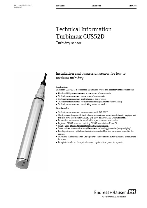
Products Solutions Services TI01136C/07/EN/01.1371237018Technical InformationTurbimax CUS52DTurbidity sensorInstallation and immersion sensor for low tomedium turbidityApplicationTurbimax CUS52D is a sensor for all drinking water and process water applications.•Final turbidity measurement in the outlet of waterworks•Turbidity measurement in the inlet of waterworks•Turbidity measurement at all stages of the process•Turbidity measurement for filter monitoring and filter backwashing•Turbidity measurement in drinking water networksYour benefits•Turbidity measurement in accordance with ISO 7027•The hygienic design with the 2" clamp means it can be mounted directly in pipes andfits into flow assemblies CUA252 (PE 100) and CUA262 (stainless steel).•Immersion version can be installed in open channels and basins.•Replaces CUS31 sensor at existing CUS31 assemblies (E and S).•Can be used at high temperatures and high pressures.•Standardized communication (Memosens technology) enables "plug and play".•Intelligent sensor - all characteristic data and calibration values are stored in thesensor.•Customer calibrations with 1 to 6 points - can be carried out in the lab or at mountinglocation.•Completely safe, as the optical source requires little power to operate.Turbimax CUS52D2Endress+HauserFunction and system designMeasuring principleThe sensor works using the 90° light scattering principle in accordance with ISO 7027 and meets all the requirements of this standard. The ISO 7027 standard is obligatory for turbidity measurements in the drinking water sector.Measurement in accordance with ISO 7027Measurement is done using a wavelength of 860 nm.Arrangement of light source and light receiver 1Light receiver 2Light sourceSensor monitoringThe optical signals are continuously monitored and tested for plausibility.In the case of discrepancies, an error message is sent via the transmitter.Solid state referenceThe function and accuracy of the CUS52D sensor can be checked with the Calkit CUS52 solid state references. During factory calibration, every solid state reference is aligned with a special CUS52D sensor and can only be used with this sensor. Therefore the solid state reference and the CUS52D sensor are married (permanently assigned) to one another.The following solid state references are available:•5 FNU (NTU)•20 FNU (NTU)•50 FNU (NTU)The reference value indicated on the solid state reference is reproduced with an accuracy of ±10% when the sensor is operating correctly.Turbimax CUS52DEndress+Hauser 3ApplicationsTurbimax CUS52D4Endress+HauserMeasuring systemA complete measuring system comprises:•Turbimax CUS52D turbidity sensor•Liquiline CM44x multi-channel transmitter•Direct installation in a pipe connection (2" clamp) or •assembly:–CUA252 flow assembly or –CUA262 flow assembly or–Flexdip CYA112 assembly and Flexdip CYH112 holder system or –Retractable assembly, e.g. Cleanfit CUA451Direct installation in a pipe connection (2" clamp)1Liquiline CM44x multi-channel transmitter 2Turbimax CUS52D turbidity sensor 3Flow directionMeasuring system with flow assembly CUA2521Liquiline CM44x multi-channel transmitter 2Turbimax CUS52D turbidity sensor 3CUA252 flow assembly 4Flow directionTurbimax CUS52DEndress+Hauser 5Measuring system with flow assembly CUA2621Liquiline CM44x multi-channel transmitter 2Turbimax CUS52D turbidity sensor 3CUA262 flow assembly 4Flow directionMeasuring system with retractable assembly 1Turbimax CUS52D turbidity sensor2Liquiline CM44x multi-channel transmitter 3Cleanfit CUA451 retractable assembly 4Flow directionTurbimax CUS52DMeasuring system with immersion assembly1Flexdip CYH112 holder system4Flexdip CYA112 assembly2Liquiline CM44x multi-channel transmitter5Turbimax CUS52D turbidity sensor3Weather protection coverMeasuring system with immersion assembly on chain holder system1Flexdip CYH112 holder system4Flexdip CYA112 assembly2Liquiline CM44x multi-channel transmitter5Turbimax CUS52D turbidity sensor3Weather protection cover6Endress+HauserTurbimax CUS52DEndress+Hauser 7InputMeasured variablesTurbidity Temperature Measuring rangesFor measuring range up to 10 FNU, the sensor exhibits a detection limit (LOD) of 0.0015 FNU (measured in accordance with ISO 15839).Power supplyElectrical connectionThe sensor is connected as follows to the Liquiline CM442 transmitter:•using the M12 connector (version: fixed cable, M12 connector) or•using the fixed cable attached to the terminal blocks (version: fixed cable, ferrules):Sensor connectionMaximum cable length is 100 m (328 ft).CUS52D Application Turbidity 0.000 to 4000 FNUDisplay range to 9999 FNU FormazinTemperature-20 to +85 °C (-4 to +185 °F)Turbimax CUS52D8Endress+HauserPerformance characteristicsMeasured error 2% ±0.01 FNU; reference: factory calibration Wavelength 860 nmConformity Determining turbidity in accordance with ISO 7027Factory calibrationThe sensor has been calibrated in the factory for "formazin" applications.Basis: internal 20-point characteristic curveApplicationsThe formazin factory calibration is used as the basis for precalibrating additional applications and optimizing them for the different media characteristics.To adapt to a specific application, customer calibrations can be carried out with up to 6 points.DriftWorking on the basis of electronic controls, the sensor is largely free of drifts.Detection limitsResponse time >1 sec, adjustableRepeatability< 0.5 % of measured value (measuring range : 0 to 10 FNU)Application Measuring range Detection limit Formazin0 to 10 FNU (ISO 15839)0.0015 FNUTurbimax CUS52DEndress+Hauser 9InstallationInstallation instructionsOrientation and positions•Install the sensor in locations with uniform flow.•The best installation location is in the ascending pipe (pos. 1). Installation in the horizontal pipe (pos.5) is also possible.•Do not install in places where air spaces or bubbles occur (pos. 3) or where sedimentation may occur (pos. 2).•Installation in the down pipe (pos. 4) should be avoided.•Avoid fittings downstream from pressure reduction stages, as this may lead to gas emissions.Wall effects:Backscattering on the pipe wall may result in the distortion of measurement values in the case of turbidity values < 200 FNU. It is recommended that you adjust the installation.Black plastic pipes with diameter > DN 60 exhibit hardly any wall effects (<0.05 FNU). For this reason, the use of black plastic pipes is recommended.Additional information on avoiding wall effects:Orientations for pipes and assembliesTurbimax CUS52D10Endress+Hauser•Install the sensor in such a way that the light beam is not reflected (pos. 6).•Avoid sudden changes in cross-section (pos. 9). Changes in cross-section should be gradual and located as far away as possible from the sensor (pos. 10).•Do not install the sensor directly downstream from a bend (pos. 7). Instead position it as far away as possible from the bend (pos. 8).•When using reflective materials (e.g. stainless steel), the pipe diameter must be at least 100 mm (4"). It is recommended that the installation be adjusted on site.•Pipes made of stainless steel with diameter >DN 300 exhibit hardly any wall effects.Installation optionsInstallation options•with clamp connection•with Flowfit CUA252 flow assembly •with Flowfit CUA262 flow assembly•with Cleanfit CUA451 retractable assembly•with Flexdip CYA112 immersion assembly and Flexdip CYH112 holder systemInstallation with 2" clamp connectionThe installation angle is 90°.The arrow points in the direction of flow.The optical windows in the sensor must be aligned against the direction of flow.Installation with flow assembly CUA252The installation angle is 90°.The arrow points in the direction of flow.The optical windows in the sensor must be aligned against the direction of flow.Installation with flow assembly CUA262The installation angle is 90°.The arrow points in the direction of flow.The optical windows in the sensor must be aligned against the direction of flow.Turbimax CUS52DEndress+Hauser 11For automatic sensor operation in pipe fittings or flow assemblies, there is the option of using the ultrasonic cleaning system CYR52 (see Accessories).Bubbles result in errors in turbidity measurements. This effect of this interference can be minimized by using a bubble trap (see Accessories).Installation with retractable assembly CUA451Arrow points in the direction of flow.The recommended installation angle is 90°.The optical windows in the sensor must be aligned against the direction of flow.When using the assembly manually, the medium pressure must not exceed 2 bar (29 psi).Installation with flow assembly CUS31-SThe recommended installation angle is 90°.The alignment of the sensor depends on the mediumFor depositing, low outgassing media the optical windows in the sensor must be aligned downwards ( see figure on the left).For non-depositing, strong outgassing media the optical windows of the sensor must be aligned upwards.Installation with immersion assemblyThe arrow points in the direction of flow.The installation angle is 0°.If you are using the sensor in open basins, the sensor must be installed in such a way that bubbles cannot accumulate on it.Turbimax CUS52D12Endress+HauserEnvironmentAmbient temperature -20 to 85 °C (-4 to 185 °F)Storage temperature -20 to 70 °C (-4 to 158 °F)Degree of protectionIP 68 (test condition: 1.8 m (5.91 ft) water column over 20 days, 1 mol/l KCl)ProcessProcess temperature -20 to 85 °C (-4 to 185 °F)Process pressure 0.5 to 10 bar (7 to 145 psi) absoluteMinimum flowNo minimum flow required.For solids which have a tendency to form deposits, ensure that sufficient mixing is performed.Turbimax CUS52DEndress+Hauser 13Mechanical constructionDesign, dimensionsDimensions in mm (inch)Compressed air cleaningCUS52D with compressed air cleaningCompressed air cleaningConsumption: 50 l/min (13.2 gal/min)Back pressure: 1.5 to 2 bar (22 to 30 psi) Connection: 6/8 mm or 6.35 mm (¼")Turbimax CUS52D14Endress+HauserSolid state referenceDimensions in mm (inch)Weight Sensor with 7 m cable MaterialsProcess connectionsG1 and NPT ¾"2" clamp (depends on sensor version)/ DIN 32676With Tri-Clamp approx. 1.56 kg Without Tri-Clampapprox. 1.48 kgSensorStainless steel 1.4404 (AISI 316 L) Optical windows Sapphire O-ringsEPDMTurbimax CUS52DEndress+Hauser 15Certificates and approvalsElectromagnetic compatibilityInterference emissions and interference immunity in accordance with EN 61326: 2005, Namur NE 21:2007Ordering informationOrder codeYou can generate a valid and complete order code on the internet using the Configurator:/cus52d 1.2.Click on "Configure this product".3.The Configurator opens in a new window. You can now configure your device and will receive a valid and complete order code for it.4.Now export the order code as a PDF or Excel file. To do this, click on the relevant button at the top of the page.Scope of supplyThe scope of supply comprises:•1 Turbimax CUS52D sensor in the version ordered •1 Operating Instructions BA01275C/07/ENTurbimax CUS52D16Endress+HauserAccessoriesAssembliesFlowfit CUA252 flow assembly •For CUS52D•Order as per product structure (--> Online Configurator, /cua252)•Technical Information TI01139C/07/ENFlowfit CUA262 flow assembly •For CUS52D•Order as per product structure (--> Online Configurator, /cua262)•Technical Information TI01152C/07/ENCleanfit CUA451 retractable assembly•Manual retractable assembly made of stainless steel with ball valve shut-off for turbidity sensors •Order as per product structure (--> Online Configurator, /cua451)•Technical Information TI00369C/07/ENFlexdip CYA112 immersion assembly•Modular assembly system for sensors in open basins, channels and tanks •PVC and stainless steel version•Order as per product structure (--> Online Configurator, /cya112)•Technical Information TI00432C/07/ENHolder systemFlexdip CYH112 holder system for Flexdip CYA112 water and wastewater assemblies •Modular holder system for sensors and assemblies in open basins, channels and tanks•The holder system can be secured in any way, be it on the floor, the cap stone, the wall or directly on a railing.•Stainless steel version•Order as per product structure (--> Online Configurator: /cyh112)•Technical Information TI00430C/07/EN Compressed air cleaningCompressed air cleaning for CUS52D •Connection: 6 mm •Materials: PE black •Order no.: 71242026Compressed air cleaning, dimensions in mm (inch)X6 mm hose nozzleTurbimax CUS52DEndress+Hauser 17Compressor•For compressed air cleaning •230 V AC order no. 71072583•115 V AC order no. 71194623Bubble trapBubble trap•For sensor CUS52D•Process pressure: up to 3 bar (43.5 psi)•Process temperature: 0 to 50 °C (32 to 122 °F)•Adapter to D 12 with connection for vent line (top connection on CUA252), is included in the delivery.•Orifice plates for the following volume flow rates:–< 60 l/h (15.8 gal/hr)–60 to 100 l/h (15.8 to 26.4 gal/hr)–> 100 l/h (26.4 gal/hr)•The vent line is fitted with a PVC hose, hose check valve and a Luer lock adapter.•Order number, suitable for assembly CUA252: 71242170•Order number, suitable for assembly S of CUS31: 71247364Bubble trap, dimensions in mm (inch)1Inlet for medium (without hose system)2Outlet for bubbles (hose system is included in scope of supply)3Outlet for medium (without hose system)Calibration setCUY52 calibration set •For CUS52D•Order as per product structure (--> Online Configurator, /cuy52)•Technical Information TI01154C/07/ENUltrasonic cleaningUltrasonic cleaning system CYR52•For attachment to assemblies and pipes•Order as per product structure (--> Online Configurator, /cyr52)•Technical Information TI01153C/07/ENTransmitterLiquiline CM44x/CM44xR•Multi-channel transmitter for connecting digital sensors with Memosens technology •Field device (CM44x) or DIN rail device (CM44xR)•Power supply 100 to 230 V AC, 24 V AC/DC •Universally extensible •Slot for SD card•Order as per product structure (--> Configurator on product page)•Technical Information TI00444C/07/EN (CM44x) or TI01112C/07/EN (CM44xR)254 (10.0)12Turbimax CUS52D 18Endress+HauserTurbimax CUS52DEndress+Hauser19。
浊度计操作规程

浊度计操作规程一、引言浊度计是一种用于测量液体中悬浮颗粒浓度的仪器,广泛应用于环境监测、水质检测、饮用水处理等领域。
为了确保浊度计的准确性和可靠性,在操作浊度计时需要遵循一定的操作规程。
本文将详细介绍浊度计的操作步骤和注意事项。
二、操作步骤1. 准备工作a. 确保浊度计处于水平放置的状态,并检查仪器表面是否有污垢或损坏。
b. 检查电源线是否连接稳固,并确保电源电压符合浊度计的要求。
c. 打开浊度计电源开关,待仪器预热一段时间后开始操作。
2. 校准浊度计a. 使用标准液体进行校准。
选择适当的标准液体,根据浊度计的仪器说明书确定校准方法。
b. 将标准液体倒入浊度计的测量槽中,待测量值稳定后记录校准值。
c. 根据校准值进行调整,确保测量结果的准确性。
3. 测量样品a. 准备待测样品,并确保样品容器干净无污染。
b. 将样品倒入浊度计的测量槽中,注意避免气泡的产生。
c. 等待测量值稳定后记录测量结果。
4. 清洁浊度计a. 测量完毕后,将浊度计的测量槽清空,并用纯水进行冲洗。
b. 使用干净的纸巾或棉布轻轻擦拭仪器表面,确保无水迹或污垢残留。
5. 关闭浊度计a. 关闭浊度计的电源开关,断开电源线。
b. 将浊度计放置在干燥通风的地方,避免阳光直射和潮湿环境。
三、注意事项1. 操作人员应具备相关的测量知识和技能,遵循操作规程进行操作。
2. 在进行测量前,应检查浊度计是否处于正常工作状态,如有异常应及时维修或更换。
3. 测量样品时,应避免将样品直接接触浊度计的光学元件,以免污染或损坏。
4. 测量槽和样品容器应保持清洁,避免污染对测量结果的影响。
5. 校准浊度计的频率应根据实际情况进行,一般建议每天或每次使用前进行校准。
6. 在清洁浊度计时,应避免使用有腐蚀性或磨损性的化学物质,以免损坏仪器表面。
7. 长时间不使用浊度计时,应将其存放在干燥通风的地方,以延长其使用寿命。
四、结论按照以上的操作规程进行浊度计的操作,能够确保测量结果的准确性和可靠性。
水技术:Sievers TOC-R3 在线TOC分析仪说明书

Robust. Reliable. Responsive.WATER TECHNOLOGIESThe Sievers TOC-R3 Online Total Organic Carbon (TOC) and TotalNitrogen (TN) Analyzer is designed to solve critical industrial andenvironmental water challenges.Offering seamless operation, minimal maintenance, and enhanceduptime, the TOC-R3 uses highly efficient and reliable 1,200°C catalyst-free combustion oxidation.From source water contamination and condensate leaks to wastewateroptimization and discharge, the TOC-R3 is a peace of mind analyticaltool that provides responsiveness and repeatability when you need it.The TOC-R3 provides high instrument uptime so operators canfocus on optimization and decision making with robust, responsive,and reliable data. It is flexible and customizable to meet specificapplication needs with options for automation, parameters, andenclosures.1300 00380 EN Rev. B2OVERVIEW:COMBUSTION REDEFINED.The TOC-R3 uses 1,200°C complete combustion oxidation followed by proven NDIR detection of the evolved CO 2. To maximize uptime, the TOC-R3 has a revolutionary industrial design with minimal moving parts and carries out sample combustion in a ceramic reactor with no catalyst needed, ensuring low maintenance and reducing cost of ownership.• Measures total carbon (TC), total inorganic carbon (TIC), total organic carbon (TOC), and non-purgeable organic carbon (NPOC).• Offers unique volatile organic carbon (VOC) detection through a reliable and accurate photoionization detector (PID).• Provides additional total bound nitrogen (TN b ) detection using a simple, lightweight, and small electrochemical detector (ECD).KEY FEATURES:300 00380 EN Rev. B3INDUSTRIES & APPLICATIONS:300 00380 EN Rev. BCOMPLIANCE:• US EPA Method 415.1 – Method determines organic carbon in drinking, surface, and saline waters; domestic and industrial wastes• US EPA Method 415.3 – Measurement of total organic carbon, dissolved organic carbon, and specific UV absorbance at 254 nm in source water and drinking water • DIN EN 1484/ISO 8245 – Guidelines for the determination of total organic carbon (TOC) and dissolved organic carbon (DOC) in drinking, ground, surface, sea, and wastewater• ASTM D5173 – Standard Guide for On-Line Monitoring of Total Organic Carbon in Water by Oxidation and Detection of Resulting Carbon Dioxide • SM 5310B – Standard Methods 5310B High-Temperature Combustion TOC Method• HJ 501 – Water quality - Determination of total organic carbon—Combustion oxidation nondispersive infrared absorption method• DIN EN 12260 – Determination of nitrogen - Determination of bound nitrogen (TNb), following oxidation to nitrogen oxidesSuperior Robust Analytical Performance• Predictive diagnostics and status monitoring• Minimal and simple maintenance withmodular design• Broad analytical ranges and protection classesfor environmentsUltimate Reliability• Complete oxidation of hard to degrade compounds• Elimination of interference and downtimedue to catalyst failures• Automated calibration, self-cleaning, andcheck standard capabilityEnhanced Responsiveness• Quick 3-5 minutes analysis time• Optional Leak Detection Mode for alert ofa leak• Optional Broad Range Detector to detect high andlow values4300 00380 EN Rev. B5• Distinctive Photoionization Detector (PID) for Volatile Organic Carbon (VOC) Detection • Total Nitrogen with Electrochemical Detector (ECD)• Communication Box (Streamlined SCADA Connections)• Air Box - Stand Alone Carrier Gas System (Avoid using plant air)• Explosion Proof Enclosures: ATEX, IECEx, C1D2• COD/BOD Conversion• Automated internal dilution for range extension • Particulate sampler for high particulate loaded streams • Mounting RackAdaptable for different applications300 00380 EN Rev. B6*Requires the purchase of an Optional Detector; either PID Detector (for POC/VOC) or ECD Detector (for TN b ).The analyzer cannot be configured with both purchasable detectors.300 00380 EN Rev. B2022 300 00380。
浊度仪使用说明书
浊度仪使用说明书一、原理浊度是表现水中悬浮物对光线透过时所发生的阻碍程度。
水中含有泥土、粉尘、微细有机物、浮游动物和其他微生物等悬浮物和胶体物都可使水中呈现浊度。
本浊度仪采用900散射光原理。
由光源发出的平行光束通过溶液时,一部分被吸收和散射,另一部分透过溶液。
与入射光成900方向的散射光强度符合雷莱公式:s I =λ2KNV ×0I 其中:0I ——入射光强度 s I ——散射光强度N ——单位溶液微粒数 V ——微粒体积λ——入射光波长 K ——系数在入射光恒定条件下,在一定浊度范围内,散射光强度与溶液的混浊度成正比。
上式可表示为:I I s = K ′N (K ′为常数)根据这一公式,可以通过测量水样中微粒的散射光强度来测量水样的浊度。
二、主要技术性能本浊度仪是高精度测量仪,采用四位LED 数字显示,具有自动切换量程,稳定准确,使用方便等特点。
广泛适用于食品、石油、化工、环境监测、医药卫生等部门行业。
1. 测量范围:0~1000度。
分0~5、5~25、25~100、100~400、400~800、800-1000六个量程(度是1个Formazine 浊度单位,对于散射式仪器,即1NTU )。
2. 精确度:≤± 2 % (满量程) 3. 重现性:≤ ±2 % (满量程) 4. 分辨率:0.01 NTU 5. 每小时漂移:< 0.1 NTU 6. 外形尺寸:282mm×237mm×102mm 7. 重量:2.2kg8. 仪器在开机通电半小时后可在下列环境下连续运行:⑴ 环境温度: 5~40℃ ⑵ 相对湿度: ≤70%⑶供电电源: AC(220±10%)V; 50Hz⑷避免强光直接照射,无显著的振动及强电磁干扰三、结构图一前面板示意图1.LED显示屏2.键盘①“↑”、“↓”:在标定或校准曲线时,按两键可更改(0-9)的数字大小。
②“←”、“→”键:在标定或校准曲线时,移动光标作用。
浊度计操作规程

浊度计操作规程1. 引言浊度计是一种用于测量液体中悬浮颗粒物浓度的仪器。
本操作规程旨在指导操作人员正确、安全地使用浊度计进行测量,并保证测量结果的准确性和可靠性。
2. 仪器准备2.1 确保浊度计处于正常工作状态,检查仪器外观是否完好无损。
2.2 检查仪器电源是否正常连接,确认电源电压符合要求。
2.3 检查浊度计的测量光束通道是否干净,如有污染应及时清洁。
2.4 检查浊度计的测量单元是否校准准确,如有需要应进行校准。
3. 样品准备3.1 根据测量要求选择合适的样品容器,并确保容器内表面干净无污染。
3.2 将待测样品倒入样品容器中,注意避免样品溅出或溢出。
3.3 如测量要求,可进行样品的预处理,如过滤或稀释等。
4. 测量操作4.1 将样品容器放置在浊度计测量台上,并确保样品与测量光束垂直通过。
4.2 打开浊度计电源,等待仪器自检完成。
4.3 在浊度计控制面板上设置测量参数,如测量波长、时间间隔等。
4.4 点击测量按钮,开始测量过程。
4.5 在测量过程中,避免移动或震动样品容器,以免影响测量结果。
4.6 等待测量过程完成,记录测量结果。
5. 数据处理5.1 将测量结果转化为所需的浊度值,根据需要进行单位换算。
5.2 如有多次测量结果,可计算平均值并记录。
5.3 对测量结果进行分析和比较,根据需要进行统计处理。
6. 仪器维护6.1 测量结束后,关闭浊度计电源。
6.2 清洁样品容器,避免残留物对下次测量的影响。
6.3 定期对浊度计进行校准,保证测量准确性。
6.4 定期清洁浊度计的测量光束通道,避免污染影响测量结果。
6.5 如发现浊度计故障或异常,应及时联系维修人员进行检修。
7. 安全注意事项7.1 在操作浊度计时,应穿戴适当的个人防护装备,如实验手套、护目镜等。
7.2 注意操作过程中的电源安全,避免触电事故发生。
7.3 避免样品溅出或溢出,避免皮肤接触有害物质。
7.4 注意操作过程中的仪器安全,避免损坏或意外事故发生。
SIGRIST在线浊度计的原理和应用
SIGRIST在线浊度计的原理和应用李宝华摘要:分析仪器正在向在线化、现场化、测控一体化方向发展。
在线分析仪表或过程分析仪表对流程工业的工艺控制和优化起到关键作用,连续实时监测工业生产过程中的原料、中间产品、产品以及相关辅助原料、副产品等物料性能指标,能够更好地优化生产操作、稳定产品质量和提高经济效益。
应用在线分析仪表也成为现代化工业生产的标志。
瑞士SIGRIST光度计有限公司(SIGRIST-PHOTOMETER AG)的在线浊度计是一种光学分析仪器/在线分析仪表,具有创新技术、测量精确、稳定可靠和极少维护的显著特点,成功应用在化工/制药过程中的纯度控制、酿造业的啤酒/白酒/葡萄酒/工艺水的过滤监测以及离心机/分离机/回旋沉淀的过程监测、油品/糖液/食品的浊度测量。
关键词:在线分析仪表;SIGRIST;在线浊度计;原理和应用引言仪器是认知世界的工具,是用于对物质实体及其属性进行观察、监视、测定、验证、记录、传输、变换、显示、分析处理与控制的各种器具和系统的总称。
化工、石油、电力等行业将用于测量热工量、电工量(如压力、温度、液位、流量、速度、电压、电流等)的仪器习惯称为仪表。
仪器和仪表没有清晰的界线划分,统称为仪器仪表。
中国的仪器仪表行业有20多个专业类别,大致划分为6大类,分类中也存在许多交叉,随着科技进步和创新,其应用领域不断拓展。
分析仪器归类于科学仪器大类,正在向在线化、现场化、测控一体化方向发展。
在线分析仪表(on-line analyzers)或过程分析仪表(process analyzers)就和工业自动化仪表和控制系统大类存在着交叉。
在线分析仪表直接安装在生产流程中,执行对物料的组成成分或物性参数的自动连续测量分析,和工业自动化仪表和控制系统融合在一起。
在现代化制造业中,尤其是流程工业更加重视不同于常规测量手段的过程分析技术,在线分析仪表常对工艺控制和优化起到关键作用,连续实时监测工业生产过程中的原料、中间产品、产品以及相关辅助原料、副产品等物料性能指标,能够更好地优化生产操作、稳定产品质量和提高经济效益。
美国HF在线浊度计操作说明书
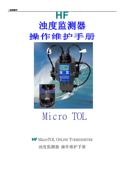
上海谷雨环HF 浊度浊度监测器监测器操作维护手册Micro TOLHF MicroTOL O NLINE T URBIDIMETER浊度监测器 操作维护手册上海谷雨环一. 规格 (2)二. 外部尺寸标示图 (3)三. 结构说明图 (3)四. 电路端子接线图 (4)五. 操作显示屏 (5)六. 校正步骤 (6)七. 操作功能说明 (7)八. 测定槽保养分解图功能说明 (13)九. 疑难排解&维护 (14)十. 日常保养 (15)一、规格型号Micro TOL准确度测量读值2%之内(低于40NTU) 测量读值5%之内(低于40NTU)测量范围0 to 100.0 NTU 0 to 1000.0NTU分辨率0.0001 NTU(低于10NTU)显示器多行且背光LCD显示清洗功能超音波自动清洗通讯接口RS-485警报接点两组且可任意设定值接点容量120~240 VAC 2A From C 接点模拟输出 4 to 20 mA 600Ω制程水压要求414kpa(60psi)流量速率100ml/min.~1 liter/min操作温度0℃~50℃电源输入90~250VAC,47~63Hz,80VA接液材质Nylon, Borosilicate Glass, Silicon, Polypropylene, Stainless Steel, CAB防水等级IP66/NEMA 4X使用环境建议室内使用,海拔高度达2000米相对湿度达到95%RH。
制造及认证标准U.SEPA180.1,ISO7027,CE Approved, ETL Listed UL3111-1& ETL Certified to CSA22.2 No.1010-1-92二、外部尺寸标示图上方高度请保持至少20公分紧急状态排水管排出处 尺寸16mm I.D.出水软管排出处4.75mm I.D. 8mmO.D.软管排风孔备压调整阀,控制流率 避免管内气泡。
浊度计E+H_Turbimax_CUE21操作手册
Here, you can find all the important steps for configuring your measuring point. Æ
Calibration
This section explains all necessary steps to calibrate the instrument. Æ
9.5 Return . . . . . . . . . . . . . . . . . . . . . . . . . . . . . . . . . . 34 9.6 Disposal . . . . . . . . . . . . . . . . . . . . . . . . . . . . . . . . . 34
6 Commissioning. . . . . . . . . . . . . . . . . . 18
6.1 Function check . . . . . . . . . . . . . . . . . . . . . . . . . . . 18 6.2 Switching on . . . . . . . . . . . . . . . . . . . . . . . . . . . . . 18 6.3 Instrument configuration . . . . . . . . . . . . . . . . . . . . 18 6.4 Instrument calibration . . . . . . . . . . . . . . . . . . . . . . 24
Operating Instructions
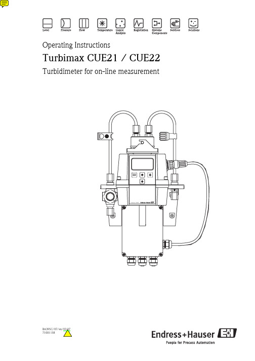
Turbimax CUE21 / CUE22
Turbidimeter for on-line measurement
- 1、下载文档前请自行甄别文档内容的完整性,平台不提供额外的编辑、内容补充、找答案等附加服务。
- 2、"仅部分预览"的文档,不可在线预览部分如存在完整性等问题,可反馈申请退款(可完整预览的文档不适用该条件!)。
- 3、如文档侵犯您的权益,请联系客服反馈,我们会尽快为您处理(人工客服工作时间:9:00-18:30)。
10863E
服务手册
服务工程师维修和修改仪表时的操作指南
10889E
数据表
仪表介绍和技术数据
10905DEF
声明和宣誓
遵循的基本法令和标准
版权保护:本参考手册由 SIGRIST-PHOTOMETER 公司所著,本手册的拷贝或
修改以及给第三方使用必须经过 GIGRSIT-POTOMETER 公司授权许可。
表) ■C4 Fouling
Adjustment 调节
同时参考: ■1. 7.5 节 ■2. 8 节 ■操作手册
1.000
当前修正系数,这个系数 设定与出厂校准的偏差。
Initiate…执行
同时参考: 操作手册
执行校准,根据标称值和 实测值计算出一个新的修 正系数。
3.5.Menu:Sensor Check(探头自检菜单)
2.2.1 控制单元上拨码开关的位置和功能
5
图 2 : 拨码开关的位置
① 拨码开关组 S1
S1/1-2
拨码开关组 S2
S2/1
②
S2/2
光度计 S485 的调节电阻。必须在 ON 的位 置。
在 ON 位 置 时 : 内 部 电 压 源 用 于 驱动输入输出。这些输入输出连接到 SICON 的地线上。 在 OFF 位置时:外部电压源用于驱动输入 输出。 此时输入输出电源的地独立于 SICON 的地。
危险符号:下面是本手册中出现的所有危险符号的解释说明
由于点击导可能致人身严重损伤或死亡的危险, 不注意观察这些危险警告信息可能会导致被点击或死亡 由于爆炸可能导致人身严重损伤或死亡的维修,不注意观察这些提示可能导 致主要设备、材料损坏或人身伤害
长期作用可能导致人身伤害或健康伤害的警告
3
可能造成设备和材料损坏的提示,忽略这个提示可能会造成仪表及其外设材 料损坏。 象形图标 下面是本参考手册中所使用的象形图标所表示的意义
9
测量通道的显示顺序总是不变的:
■7.179EBC(图中所示例子),当前
测量值及其单位。
③
■C1 Turb90°(图中所示),测量通 道名称(—操作手册)。
■ 7.100-7.200 ( 图 中 所 示 ) 对 应 通
道当前测量值图示范围。(-操作手
册)
3.3 Info 按钮
当前输出(I1…I4)的信息
TurBiScat 和 SICON 参考手册
在线浊度测量仪表和控制单元
1
目录 1.一般用户信息------------------------------------------------ 2 2.机械设计---------------------------------------------------- 4
7.1.总体介绍------------------------------------------- 46 7.2.更换控制单元--------------------------------------- 47 7.3.更换控制电缆--------------------------------------- 47 7.4.更换一次表----------------------------------------- 49 7.5.标记校准检查单元的标称值--------------------------- 50 8.制备福尔马肼标准液------------------------------------------ 51 9.附录-------------------------------------------------------- 52
1. 一般用户信息
参考手册的用途:参考手册为仪表用户提供比操作手册更详细的补充信息,
指导用户对仪表进行操作。
参考手册使用对象:参考手册主要是为所有熟悉操作手册,而且需要更详细
信息的设计、配置和维修等人员所准备的。
其它附加资料:
资料号
题目
内容
10860E 10862E
操作手册 简明手册
仪表生命周期中最重要的信息和操作指南 最重要的内容和完整的菜单结构
菜单
功能描述
数值和参数
Sensor Check 探 探头检查
参考手册的存放位置:本手册是产品的一部分,必须存放与方便取的地方。
最新版本(彩色的)可以到 网站下载(只需一次性注
册即可)。
另外,除 IGRIST-PHOTOMETER 公司之外,本手册也可以由有资质的 SIGRIST-
PHOTOMETER 代理商提供。(见操作手册中的用户信息)。
2.2.1 节)
③
使用内部电源时的共享地
③
输出 DIL 拨码开关 S2/1(off)
2.2.3 输入
输入设计为光电耦合输入。所有的光电耦合输入都可以独立的接入最 高 50V 电源的开关量输入。
输入的功能描述见 3.9 节。
7
图 4:输入逻辑图
控制电压:要使用内部电压源,DIL ① 拨码开关 S2/1 必须是闭合状态(见 ②
2.2.1 节)
③
使用内部电源时的共享地
③
输出 DIL 拨码开关 S2/1(off)
3. 菜单功能介绍
3.1 介绍
■根据不同的仪表(90°或 25°单角度,90°/25°双角度,色度),根据测量
角度的不同,这里所描述的菜单结构及选择项可能会稍有不同。
■由光度计所生成的菜单通过 SICON 操作和通过网页操作是相同的。两者的操
2
9.1.用户自定义曲线---------------------------------------- 52 9.2.菜单结构和出厂设置(英语)---------------------------- 54 10.索引------------------------------------------------------- 58
当前论题下的附加信息
对光度计和控制单元进行维护等操作时的实际过程
对控制单元进行操作
在电脑上操作
2. 机械设计 2.1 TurBiScat 设计
4
① 探头头部 ③ 光学单元 ⑤ 干燥剂 ⑦ 隔离环
2.2 SICON 设计
图 1:
TurBiScat 的设计 ② 探头外壳(截面图) ④ 电子部件 ⑥ 拆卸电子单元的按钮
校准 C1..C4 Actual Value 实测值
数值和参数
仪表特性
同时参考: ■1.第 8 节 ■2.操作手册
和仪表匹配的校准单元或 福尔马肼溶液的值。
仪表特性
当前测量值
可选操作对下 列通道都是有
效的 ■C1 Turb90° ■C2 Turb25° Curr.corr 当前修正
■C3 Color (仅限于有色 度可选件的仪
2.1.光度计 Turbiscat 设计-------------------------------- 4 2.2.控制单元 SICON 设计---------------------------------- 5 3.菜单功能介绍------------------------------------------------ 8 3.1.通用介绍--------------------------------------------- 8 3.2.Diag 按钮-------------------------------------------- 9 按钮-------------------------------------------- 10 3.4.菜单:Recalibration(再校准)------------------------ 10 3.5.菜单:Sensor check(探头自检)----------------------- 11 3.6.菜单:Simulation(仿真)----------------------------- 11 3.7.菜单:Limit(限位)---------------------------------- 12 3.8.菜单:Curr.outputs(电流输出)----------------------- 14 3.9.菜单:In./outputs(输入输出)------------------------ 18 3.10.菜单:Digi.interf(数字接口)----------------------- 19 3.11.菜单:Logger(记录)-------------------------------- 20 3.12.菜单:configuration(设置)------------------------- 21 3.13.菜单:Meas.channels(测量通道)--------------------- 23 3.14.菜单:Math.channels(数学通道)----------------------- 27 3.15.菜单:Spec.funct(特殊设定)-------------------------- 28 3.16.菜单:History(历史)------------------------------- 29 3.17.菜单:System info(系统信息)----------------------- 31 3.18.菜单:Changing display setting(显示设置)---------- 33 4.SD 卡数据写入与读取----------------------------------------- 35 4.1.SD 卡从仪表上拆下并接到电脑上------------------------ 35 4.2.鉴定诊断数据----------------------------------------- 36 4.3.加载软件版本----------------------------------------- 36 4.4.拷贝历史数据到电脑上备用----------------------------- 37 5.使用网页接口操作仪表---------------------------------------- 37 5.1.用户 web 接口的投用---------------------------------- 37 5.2.用户 web 页面的操作---------------------------------- 39 6.现场总线接口------------------------------------------------ 41 6.1.介绍------------------------------------------------ 41 6.2.Modbus---------------------------------------------- 42 6.3.Profibus DP----------------------------------------- 44 7.维修工作---------------------------------------------------- 46
