Kromschroder 点火器 IES258-5
IES258烧嘴控制器使用说明书

IES258烧嘴控制器使用说明书一、概述IES258烧嘴自动控制器是一种直接启动和监测烧嘴运行的控制器;可采用电离式火焰监测或紫外线UV监测,也可采用点火和监测共一根电极进行操作的模式;本控制器适用于不用吹扫或吹扫由其它控制的系统中,直接点火功率不大于350KW带助燃风的烧嘴;具有本地开关、远程按钮复位两种模式。
本控制器符合欧洲燃气应用标准EN298。
二、技术指标1、供电:AC220V±10% 50HZ2、环境温度:-20℃ 60℃,无冷凝3、火焰检测电流:2-20uA之间调节4、防护等级:IP405、点火电缆:<5米(宜用耐温高压线)6、电缆长度:电离监测方式最长75米,UV监测方式最长100米。
三、控制面板说明四、安装及接线注意事项:1、电源应采用固定接线,火线L和零线N不可以接反,否则会造成设备损坏。
2、电磁阀和点火变压器由控制器输出220AC电源驱动,最大输出电流为2A,每个输出电流不得超过2.5A。
3、燃烧指示触点(端子13-14)和故障信号触点(端子8-9):最大电流:2A,最大电压:253V。
4、UV紫外线火焰探测器最大工作电压为:230V,内部无熔断保护器。
5、采用单电极时,烧嘴和控制器的7#端子一定要接地,否则会造成设备损坏。
6、采用UV紫外探头时,7#端子不要接地。
7、端子11和12已在内部并接。
8、安装:可用U型35mm导轨安装,长度为113mm,或在底板上两安装孔上直接螺丝安装,安装孔间距为70 mm。
本控制器为宽113,高75,深120。
9、检测线用塑料电缆保护管单独走线,远传时要和主电缆分开放置,以免外部的电磁干扰。
采用电离监测方式和UV监测方式而且检测线长>5米时,建议检测线采用>500VAC的屏蔽电缆,采用单电极测检方式而且距离>5米时,建议采用>20KV 的屏蔽电缆。
10、控制器通电前必须将控制器上的两个固定螺丝旋紧;11、二次点火时要待报警灯红亮后20秒方可进行,以免过载损坏。
krom点火控制器说明书

Steuerung erfolgt. Typische Anwendungsgebiete
sind industrielle Thermoprozessanlagen nach
EN 746 in der Eisen-, Stahl-, Glas- und
Keramikindustrie,
sowie
der
Gasfeuerungsautomaten Automatic burner control units IFS 258
6.1.1.5 Edition 9.01CN
IFS 258
Gasfeuerungsautomaten IFS 258
Flammenüberwachung mit Ionisationsfühler oder mit UV-Sonde Zündung und Überwachung mit einer Elektrode möglich Lange Fühlerleitungen möglich Abschaltempfindlichkeit für den Flammenstrom stufenlos einstellbar Messbuchsen zur unterbrechungsfreien Flammenstrom-Überprüfung Wiederanlauf oder sofortige Störabschaltung nach Flammenausfall, umschaltbar Meldekontakte für Betrieb und Störung EG-Baumuster geprüft und zertifiziert
IFS 258
mA ≤
TZI
VU
VG..L
GIK
IFS 258
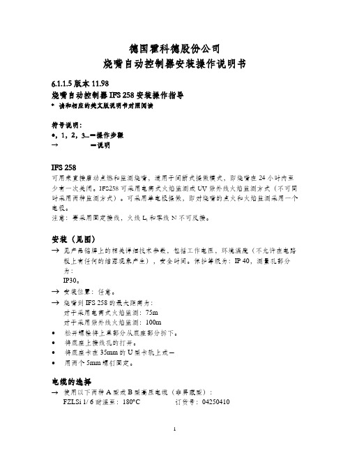
德国霍科德股份公司烧嘴自动控制器安装操作说明书6.1.1.5 版本11.98烧嘴自动控制器 IFS 258安装操作指导* 请和相应的英文版说明书对照阅读符号说明:∙,1,2,3...=操作步骤→=说明IFS 258可用来直接启动点燃和监测烧嘴,适用于间断式操做模式,即烧嘴在24小时内至少有一次关闭。
IFS258可采用电离式火焰监测或UV紫外线火焰监测方式(不可同时采用两种监测方式)。
可采用单电极操做,即对烧嘴的点火和火焰监测采用一个电极。
和零线N不可反接。
注意:要采用固定接线,火线L1安装(见图)→见产品铭牌上的相关详细技术参数,包括工作电压,环境温度(不允许在电路板上有任何的结露现象产生),安全时间。
保护等级为:IP 40,测量孔部分为:IP30。
→安装位臵:任意。
→烧嘴到IFS 258的最大距离为:对于采用电离式火焰监测:75m对于采用紫外线火焰监测:100m∙松开螺栓将上盖部分从底座部分拆下。
∙将底座上接线孔的打开。
∙将底座卡在35mm的U型卡轨上或-∙用两个5mm螺钉固定。
电缆的选择→使用以下两种A型或B型高压电缆(非屏蔽型):FZLSi 1/ 6 耐温至:180︒C 订货号:04250410FZLK 1/ 7 耐温至:80︒C 订货号:04250409A=火焰电离监测电缆(见图)最长:75m安装条件:要和主电缆分开放臵,以避免外部的电磁干扰。
→多条火焰监测电缆可放于同一个塑料电缆保护管中,尽量不要使用金属电缆保护管或金属电缆桥架。
如果只能使用金属电缆保护管,以上所述电缆最长有效距离无法保证。
B=点火电缆建议使用长度< 1m,最长=5m→分别安装,不要放于金属电缆保护管中。
→与火焰电离监测电缆或UV紫外线火焰监测电缆分别放臵。
→如电缆长度超过0.7m或有其他设备造成的干扰,使用抗干扰电极接头,阻抗为1KΩ。
C=UV 紫外线火焰监测电缆最长:100m安装条件:要和主电缆分开放臵,以避免外部的电磁干扰。
火锅 火桌自动点火安装说明书

IMPORTANT SAFETY INFORMATION: READ AND FOLLOW ALL INSTRUCTIONSSave these instructions. Leave manual with homeowner after installation.Improper installation, adjustment, alteration, service, or lack of maintenance can cause injury or property damage. Readthe installation, operating, & maintenance instructions thoroughly before installing or servicing this equipment.FIRE POT / FIRE TABLEINSTALLATION INSTRUCTIONS - AUTO IGNITIONSAVE THESE INSTRUCTIONS FOR FUTURE REFERENCE®Scan with your phone for Step by Stepinstructions, or visit /tech2Do not store or use gasoline or flammable vapors and liquids in vicinity of this appliance.Do not install this appliance near any combustibles. A Liquid Propane cylinder not connected for use shall not be stored in the vicinity of this or any other appliance.RISK OF SHOCK OR ELECTROCUTION. Hazardous voltage can shock, burn and cause death or serious property damage.Installation must be performed by a licensed professional. Improper installation, adjustment, alteration, service or maintenance can cause injury or property damage. Installer must follow all local codes as well as National Fuel Gas Code, ANSI Z223.1.This product must be installed by a licensed or certified electrician or a qualified pool professional in accordance with the National Electric Code (NEC) or Canadian Electric Code (CEC), CSA C22.1.Turn off power to controls before installation/service. Failure to comply will either damage or destroy the product and will void the warranty.To reduce the risk of injury, do not permit children to use this product.If you smell gas, shut off the gas to the appliance and extinguish any open flame. If the odor lingers keep away from appliance and immediately call gas supplier or fire department. Do not leave any flame unsupervised.Gas pressure should not exceed 1/2 psi.Carbon Monoxide Hazard: This appliance can produce carbon monoxide which as no odor. Using it in anenclosed space can cause serious injury or death. Never use this appliance in an enclosed space such asa camper, tent, car or home..HOT! DO NOT TOUCH. SEVERE BURNS MAY RESULT. CLOTHING IGNITION MAY RESULT.Glass and other surfaces are hot during operation and cool-down. CAREFULLY SUPERVISE children near this appliance. Alert children and adults to hazards of high temperatures.IMPORTANT WARNINGS & SAFETY INSTRUCTIONSREAD AND FOLLOW ALL INSTRUCTIONSSAVE THESE INSTRUCTIONSADHERE TO ALL LOCAL CODES CONCERNING INSTALLATION AND OPERATION.• For outdoor use only.• Product is not intended to be a starter for wood or any other combustibles. • Test for gas leaks prior to use.• Verify correct gas fuel type. Never use an alternative fuel, including bio-fuel, ethanol, lighter fluid or any other fuel.• Installation must be performed by licensed gas piping professional.• When product is not in use for an extended period, turn off gas to prevent unwanted start-up.• The use of a cover when not in operation is recommended.•Verify gas shut off is located outside of the product or column. The gas shutoff should NOT be used to adjust flame height.• An approved gas valve or keyed valve shall be installed upstream of the unit and located in an accessible area that is within 5ft from the unit.Do not modify units from factory configuration. Doing so will void the warranty.Manufacturer is not responsible for damage due to improper installation.NOTICE3B. SYSTEM REQUIREMENTSInstallation must be performed by a licensed contractor. Installer must follow all local codes as well as National Fuel Gas Code, ANSI Z223.1. We suggest that our products be serviced annually by a professional certified in the US by the National Fireplace Institute (NFI) as NFI Gas Specialists or in Canada by WETT (Wood Energy Technical Training). Installer must follow all instructions carefully to ensure proper performance and safety.This Product is for outdoor use only.GAS REQUIREMENTSELECTRICAL REQUIREMENTS• Auto ignition requires 12 VAC• The included transformer steps down from 120 VAC to 12VAC• Installer should check voltage after installation to ensure proper values•In the United States the National Electrical Code® (NEC®) and in Canada the Canadian Electrical Code (CEC), require that all metallic components of a pool structure, including reinforcing steel, metal fittings and above ground components be bonded together (forming an equipotential bonding grid) with a solid copper conductor not smaller than an 8 AWG (6 AWG in Canada).• To prevent premature failure of the appliance resulting from stray voltages and voltage differentials, the burner must be bonded to other equipment which is part of the pool plumbing system with a solid copper wire not smaller in diameter than 8 AWG (6 AWG in Canada).•The National Electrical Code® (NEC) allows listed low-voltage gas-fired lumiaires, decorative fireplaces, fire pits and similar equipment using low voltage igniters that do not require grounding, and are supplied by a listed transformer / power supply with outputs that do not exceed the low-voltage contact limit (15 V RMS ac, 30 V continuous DC) to be permitted to be located less that 1.5m (5ft) from the inside walls of the pool.• Metallic equipment, including metallic gas piping, shall be bonded in accordance with the NEC in the US, and Canadian Electrical Code (CEC) in Canada.•In the NEC and CEC require that all metallic components of a pool structure, including reinforcing steel, metal fittings and above ground components be bonded together (forming an equipotential bonding grid) with a solid copper conductor not smaller than an 8 AWG (6 AWG in Canada)41. LOCATIONDRAINAGE• Fire pot/tables should have adequate drainage for rainwater. Select a location with adequate drainage. Install abovegrade to prevent water retention.ACCESS• Leave easy adequate access for installation and maintenance.• To safely turn off the burner, you must have clear and easy access to the ON / OFF valve AFTER the appliance isconnected to the gas supply.CLEARANCE• Recommended Clearances: Sides 4 ft / Top 10 ft: Combustibles/structures not to be closer than 4’ on the horizontal plane, 10’ overhead. (FIG 1).• No combustible structure should be above the fire feature.• Do not completely enclose. No more than two side structures should be around the fire feature.• Do not recess the fire feature below ground/floor level.• Natural stone such as granite or marble must be kept away from heat and flame. Contact and close proximity can result in cracking or explosion.• Install fire features out of the way of pedestrian traffic. Provide space to allow a safe distance from the heat and flame.• Vent collars and drainage should never be obstructed.10ftOUTDOOR USE ONLYFLAMMABLE OR COMBUSTABLEITEMSFIGURE 1: A dequate Clearance2. SETUPDRAINAGE• For natural gas only, a dedicated drain line may be installed under the pot/table.• Installations using propane should not have drains located below the unit. Drainage should be achieved with ventholes in the product and/or around the column.VENTING• WARNING: All installations must have proper ventilation around and under the unit to allow possible accumulated gas to escape. Failure to do so may cause a dangerous build-up of gas and can explode.• Ventilation location must be such that any settled gas can escape.• Vents are pre-installed in the fire pot and table. If installing on an open column or pedestal, ventilation must be added to prevent dangerous gas build-up.5• The top of a column or pedestal on which fire feature is installed should be sealed around.• A minimum of two vents on opposing sides of a column are required. See Table 1 for minimum vent requirements. Multiple vents evenly spaced totaling minimum requirement or more is also acceptable. Minimum air openings shall not be less than 3 inches.• One vent should be within 12 inches of the bottom of the column and another within 12 inches from the top of the column.•Vents should not be blocked from air circulation.TABLE 1: COLUMN VENT REQUIREMENT3. GAS LINE• To eliminate unnecessary pressure drop, ensure the pipe length and amount of elbows used is minimized.• Corrugated flex hoses are known to cause a whistling sound. A whistle-free hose is recommended for gas supply to the burner.• You must have clear and easy access to the ON / OFF valve AFTER the appliance is installed and connected to the gas supply in order to safely turn off the burner.• Openings from the gas/water line should be sealed, so that gas does not collect in these spaces.• For gas pressure and BTU requirements see charts on page 3.1. AUTO IGNITION COMPONENTS• All gas and electrical connections are on the box.• Transformer: 120VAC to 12 VAC transformer is included.• Pilot Connections: Probes connect to the side of the box to the SS burner and spark electrode. There is a dedicated gas line pre-installed for the pilot flame.• Other Items• Air mixer: Pre-installed with Liquid Propane units• Flow restricter: Pre-installed with Natural Gas units• Gas flow regulator: Pre-installed with 18in flexible gas line• Shut-off valve: Not included• Air mixers required for Liquid Propane. For propane units, the correct air mixer should come pre-installed.• Do not attempt to move, adjust or remove the air mixer for LP units. Failure to do so could result in personal injury and damage to unit/property.• Vent collars for an air mixer intake on a propane system should not be obstructed.• Our units are NOT intended to be used with small portable LP tanks.63. GAS CONNECTIONa. Before beginning, ensure the gas line is turned OFF.b. Run 1/2” gas line to the inlet connection of the pre-installed regulator.• Each unit ships with a regulator pre-installed. All installations must have gas regulator installed to maintain the gas pressure to the system.• The regulator should be installed horizontally. The directional arrow should point away from the gas source and towards the gas valve.• Gas regulator should be placed near the bottom of the fire feature such that it is not affected by temperature from the burner.c. Use pipe dope/joint compound on ALL threaded fittings EXCEPT flared fittings.d. Verify all gas connections are tightened securely. ALWAYS perform leak tests and make repairs as needed.e. DO NOT daisy chain the gas lines. (See Section D)f. A shut-off valve must be installed at each fire feature or valve. The primary gas valve must be located where they canbe easily accessible so that the gas can be shut off quickly in case of an emergency.g. Keep pipe length and elbows to a minimum to eliminate unnecessary pressure drops.h. The use of a corrugated gas line can cause unwanted noise.4. ELECTRICAL CONNECTIONa. Power Requirements1. Auto ignition requires minimum 12 VAC2. The included transformer steps down from 120 VAC to 12VAC.3. Installer should check voltage after installation to ensure proper values.4. Max length of wire from the transformer to system is up to 75ft with 16 Gauge wire.5. For distances over 75ft - 150ft use 14 Gauge wire.b. Connections (Fig 2)1. Run electrical cable through an approved conduit. Conduit should be sealed to prevent gas settling or intrusion.2. Connect 120V to the included or approved Pool & Spa Rated Class 2 transformer (T).3. There are three wire connections on the side of the auto igniter. Connect 12V power from the transformer usingwire nuts (3).4. Wrap wire nuts with electrical tape or use waterproof wire nuts to prevent moisture from getting in. Make surewire nuts are positioned away from the bottom of the burner assembly.5. Connect ground from incoming power. (If required by local codes)6. Do not “daisy chain” electrical lines. (See Section D). Each transformer can supply up to four auto ignitorconnections.7. The igniter contains a bonding lug on the bottom. To install, loosen the set screw, insert the bond wire into thehole and tighten the setscrew until the bond wire is secured into place.7FIGURE 2: WIRING DIAGRAM4. CHECK SYSTEMa. Perform all above listed safety checks before start up. Before operating smell all around the appliance area for gasodors and next to the floor because some gases are heavier than air and will settle on the floor.b. Ensure any person standing close to the fire feature is aware you will be turning the fire feature on prior to actuallyturning it on.c. Do not add glass or rock media to the pan until a system test is complete.d. At each burner assembly, check that the spark electrode is arcing from the pilot to the button. You should be able tohear and see the electrode spark. If there is no spark, make sure that the burner assembly is receiving 12VAC from the control panel.e. Allow the unit to run for approximately five minutes then turn off.f. After all units have been lit, they can be adjusted for flame size.g. Turn on system and check for re-ignition.81. GLASS OR ROCK FILL MEDIA• Use only approved fire glass or rock media on burners. Incorrect media can melt or explode leading to bodily injury or product damage.• Glass media max level: fill up to 1/4in above the burner height.For glass or rock fill media, leave an airflow gap around the ventilation slots for the pilot light box.•2. BURNER SETUP• Prior to turning appliance on visually inspect fire feature to ensure debris such as leaves or other combustiblematerial has not collected inside the feature. This could burn and emit embers once the fire feature is turned on.• Each burner should have a flame height of approximately 12” – 15” from the top of the pan.• Each burner should be adjusted as required so that the flame size at each burner is similar in appearance to each other.• Install decorative rock or glass on top of the “burner support” and burner assembly. Do not completely cover/obstruct the burner.3. START UPa. WARNING: Perform all above listed safety checks before start up.b. Before operating, smell around the appliance area for gas odors and next to the floor because some gases areheavier then air and will settle on the floor.c. Ensure any person standing close to the fire feature is aware you will be turning the fire feature on prior to actuallyturning it on.d. Turn System on.e. If the system locks, reset by turning power OFF and then back ON.f. The pilot flame will ignite. The main gas valve will open after the pilot flame is lit. If main fire does not ignite, thesystem will cycle and attempt to light again.g. If the pilot flame is extinguished at any time, the system will shut down. It will automatically attempt to restart againwith the ignition sequence.h. Once installed, the gas control valve should not be used to adjust the flame.9FIGURE 4: START-UP SEQUENCE4. MAINTENANCE & CARE• If any repairs are required, contact a licensed professional.• Burner• Inspect the burner before each use of the appliance. If there is any evidence that the burner is damaged, it mustreplaced before operating.• Periodically clean the burner assembly with a wet cloth or cleaning solution to remove carbon build-up. Frequency of the cleaning will depend on usage. Clean burners as necessary using compressed air.• Periodically inspect the underside of the burner assembly for any signs of excessive temperatures.• Check that all gas connections are tight.• The burner assembly should be covered and protected from snow and ice. The burner should not be operated in high wind conditions.• Visually inspect burner holes for debris/insect infestation.• Pilot assembly requires at least yearly maintenance. Clean the carbon build up on the spark electrode and pilot using compressed air• Inspect the gas line regularly. If the line shows evidence of excessive abrasion or wear or if the line is damaged, it must be replaced before use.• USE THE SYSTEM! If the feature has been inactive for an extended period, turn fire feature on to ensure properoperation.10C. OPERATION & MAINTENANCE5. MATERIAL CARECOPPERPATINA: Dark brown to green to blue. All copper products will patina. Patina is a natural process of oxidation where copper reacts to the elements and produces a series of colors that build up in order to protect the copper. The final color can vary widely depending on location, environment and other factors.WHAT COLOR WILL MY PRODUCT BE?All products ship in their natural copper state. Depending on where they are stored or transported, patina may begin to develop. It is very likely the color may change between manufacture and delivery and will continue to patina after installation. Copper can be cleaned after installation to reset the patina process.CLEANING• Patina color may vary from piece to piece, even when delivered on the same day. If you prefer to restore the material after installation, a cleaning solution such as TarnX® may be used.• Hand Prints/Water Spots: Products develop hand prints from handling or water stains from water testing. The natural patina process will cover up the markings as the whole piece begins to darken.STAINLESS STEELPATINAStainless steel does not develop a patina.CLEANING• Stainless steel is steel that is “stain-less” however, this DOES NOT MEAN THAT STAINLESS STEEL WILL NEVER RUST OR CORRODE. Stainless steel can show water spots and deposits of minerals or other natural substances that appear orange, white and/or brown. We suggest regular cleaning, at least once a month.• Use distilled, soft or purified water (preferably warm) while cleaning and as a last rinse. Dry with a soft cloth.• General maintenance can be done with a soft cloth. Windex works well if you want to remove water spots. Otherwise a mild soap or vinegar (1 part vinegar to 3 parts water) will remove light buildup.• Try to go in the direction of the natural polishing grains• Heavier build-up can be cleaned using very fine red Scotch-Brite™ cleaning pads.• In many cases, cleaning over time will greatly reduce reappearance of build-up.SALTWATERStainless steel is not warranted for use in or around salt water. Our products are made of 316 marine grade Stainless Steel. Stainless steel can get water spots and stainless steel can get deposits of minerals or other natural substances that appeared, white and/or brown. If this happens you’ll need to clean the areas each time the build up occurs and after 3-6 cleanings the problem areas should be free of any build up returning.1112COMMON ISSUES/MISTAKES• Check line connections - do not daisy chain gas or electrical connections. (see Section C)• Check gas pressure for natural gas and propane. (see Section B)• If using with propane gas - ONLY use with air mixer correctly installed. (See Fig 2) The ½ “ air mixer for propane includes stamped marking for gas flow direction. Air mixer is not required with natural gas.• Check electrical voltage and connections.• Check ground connections. (if required)• Upon completing the gas line connection, a small amount of air will be in the lines. When first lighting the burner, it will take a few minutes for the lines to purge themselves of this air. Subsequent lighting of the appliance should not require such purging.DO NOT DAISY CHAINFIGURE 6: DAISY CHAIN GUIDE13HOW TO PERFORM A LEAK TESTa. Prepare a leak testing solution of soapy water by mixing in a spray bottle one part liquid soap to one part water.b. Make sure all the control knobs are in the OFF position.c. Turn on the gas.d. Apply the leak-testing solution by spraying it on joints of the gas delivery system. Blowing bubbles in the soapsolution indicates that a leak is present.e. Stop a leak by tightening the loose joint or by replacing the faulty part with a replacement part recommended by themanufacturer.f. Turn the control knob back to the full OFF position.g. If you are unable to stop a leak: Please consult a gas specialist. Shut off the gas supply to the feature and releasepressure in the hose and manifold. Call/consult an authorized gas appliance service technician or a liquid propane gas dealer. DO NOT use the appliance until the leak is corrected.Perform a leak test at least once a year whether the gas supply has been disconnected or not. Whenever any part of the gas system is disconnected or replaced, perform a leak test. As a safety precaution, remember to always leak test outdoors in a well-ventilated area. Never smoke or permit sources of ignition in the area while doing a leak test. Do not use a flame, such as a lighted match to test for leaks.14SAVE THESE INSTRUCTIONS INSTALLER - LEAVE THIS INSTRUCTIONS WITH HOMEOWNER Record Information on this System Below & Keep for Your RecordsInstaller _______________________________________________________________System Purchased From ______________________________________________Installation Date _____________________________Serial Number _______________________________CMP, LLC36 HERRING ROAD, NEWNAN, GA 30265/Bobe ®0621sb REV E。
IFS258使用说明
一、电缆选择A.电离电缆B.点火电缆C.UV电缆二、检查接线1、关上手动阀。
2、开启系统。
3、确认正负极接线正确。
4、开启IFS258.→绿灯将会亮。
5、将3号接线柱通电,以开启内部控制程序。
→大约3秒后,气阀必将打开,点火器点火。
→过了安全时间(3或5或10秒)之后,IFS258将会显示错误,红灯亮起,8号和9号之间的触点就会闭合。
6、打开手动阀。
三、调整一旦点火失败,所要做的:1、松开螺丝,移走上部分。
2、移走贯穿底部的标签。
3、在“直接故障锁定”和“重启”两项中选择。
→A.我们推荐在偶尔出现不稳定的燃烧情况时,进行重启操作。
B.当你进行缓慢关闭空气阀,或者连续控制的操作时,点火器在最大输出却点不着火的情况下,不要重启。
四、断电临界点1、断电临界点的范围在2-20μA之间。
(出厂设置是2μA)2、如果在点着火之前黄灯常亮,或者短暂地亮一下,请增加电位计的值。
3、测量的火焰信号将会比设定值至少大3μA。
五、常用命令1、打开手动阀。
2、开启系统。
3、开启IFS258.→绿灯将会亮。
4、将3号接线柱通电,以开启内部控制程序。
→大约3秒后,气阀必将打开,点火器点火。
→点火时间:IFS 258-3 :大约2秒IFS 258-5 :大约3秒IFS 258-10 :大约6秒→只要IFS 258识别出火焰,黄灯就会亮起。
→过了安全时间(3或5或10秒)之后,13号和14号之间的触点就会闭合。
→此时点火器出于运行状态。
TH2515 仪器说明书

Ver 2.1目录Ver 2.0 (2)第1章仪器简介与开箱安装 (8)1.1仪器简介 (8)1.2开箱检查 (8)1.3电源连接 (8)1.4保险丝 (8)1.5环境 (8)1.6使用测试夹具 (9)1.7预热 (9)1.8仪器的其它特性 (9)第2章前面板说明及入门操作 (10)2.1前面板说明 (10)2.2后面板说明 (11)2.3显示区域的定义 (12)2.4按键及其相应的显示页面 (13)2.4.1测量主菜单按键【DISP】 (13)2.4.2系统设置主菜单按键【SETUP】 (13)2.5基本操作 (13)2.6开机 (14)第3章基本操作 (15)3.1<测量显示>页面 (15)3.1.1测试功能 (15)3.1.2测试量程 (16)3.1.3测试速度 (17)3.1.4文件管理 (17)3.1.5其他工具 (17)3.2<比较显示>页面 (18)3.2.1文件管理 (19)3.2.2工具 (19)3.2.3比较 (19)3.2.4比较模式和上下限、百分比误差设置 (19)3.3<档显示>页面 (19)3.4<统计显示>页面 (21)3.4.1边界模式和其相应值的设定 (21)3.4.2统计状态 (21)3.4.3统计分析参数说明 (21)3.4.4工具 (22)3.4.5文件 (22)3.5<测量设置>页面 (22)3.6<TC/Δt设置>页面 (24)3.6.1温度校正(Temperature Correction 简称TC) (25)3.6.2温度转换(temperature conversion 简称t ) (25)3.6.3温度传感器的类型 (26)3.6.4参数设定 (27)3.6.5文件 (27)3.7<档设置>页面 (27)3.7.1文件 (29)3.7.2工具 (29)第4章系统设置和文件管理 (30)4.1系统设置 (30)4.1.1触摸音 (30)4.1.2语言 (30)4.1.3口令 (31)4.1.4总线模式 (31)4.1.5波特率 (32)4.1.6总线地址 (32)4.1.7EOC信号 (32)4.1.8Err.OUT信号 (33)4.1.9电源频率 (34)4.1.10时间和日期设定 (34)4.2<文件管理>功能页面 (34)4.2.1存储/调用功能简介 (34)4.2.2U盘上的文件夹/文件结构 (35)4.2.3DHCP (39)4.2.4IP地址 (40)4.2.5子网掩码 (40)4.2.6网关 (40)4.2.7首选DNS、备用DNS (40)第5章性能指标 (41)5.1测量功能 (41)5.1.1测量参数及符号 (41)5.1.2测量组合 (41)5.1.3等效方式 (41)5.1.4量程 (41)5.1.5触发 (41)5.1.6测试端方式 (41)5.1.7测量中的各种时间的开销 (41)5.1.8平均 (42)5.1.9显示的位数 (42)5.2测试信号 (42)5.2.1量程电流 (42)5.2.2开路输出电压 (42)5.2.3测量显示最大范围 (42)5.3测量准确度 (43)5.3.2温度测量的准确度(Pt500) (44)5.3.3温度测量的准确度(模拟输入) (45)5.3.4温度修正系数K (45)第6章远程控制 (46)6.1RS232C接口说明 (46)6.2GPIB接口说明(选购件) (47)6.2.1GPIB接口功能 (49)6.2.2GPIB 地址 (49)6.2.3GPIB总线功能 (49)6.2.4可编程仪器命令标准(SCPI) (50)6.3LAN远程控制系统 (50)6.3.1通过浏览器访问TH2515 (52)6.3.2通过上位机软件访问TH2515 (52)6.4USBTMC远程控制系统 (53)6.4.1系统配置 (53)6.4.2安装驱动 (53)6.5USBVCOM虚拟串口 (54)6.5.1系统配置 (54)6.5.2安装驱动 (54)第7章RS232命令参考 (55)7.1SCPI系统命令 (55)7.1.1DISPlay子系统命令集 (55)7.1.2FUNCtion 子系统命令集 (56)7.1.3APERture子系统命令集 (61)7.1.4TRIGer子系统命令集 (61)7.1.5FETCh?子系统命令集 (63)7.1.6TEMPerature子系统命令集 (64)7.1.7COMParator子系统命令集 (66)7.1.8BIN子系统命令集 (69)7.1.9STA Tistics子系统命令集 (73)7.1.10IO子系统命令集 (76)7.1.11MEMory子系统命令集 (77)7.1.12SYSTem 子系统命令集 (78)7.1.13SCPI公用命令 (81)7.2MODBUS系统命令 (83)7.2.1MODBUS协议说明 (84)7.2.2公用指令操作说明 (85)7.2.3DISP指令操作说明 (86)7.2.4FUNC指令操作说明 (86)7.2.5APER指令操作说明 (87)7.2.6TRIG指令操作说明 (87)7.2.7FETC指令操作说明 (88)7.2.8TEMP指令操作说明 (88)7.2.10BIN指令操作说明 (90)7.2.11STA T指令操作说明 (93)7.2.12IO指令操作说明 (94)7.2.13SYST指令操作说明 (94)第8章Handler接口使用说明及程序升级方法 (99)第9章包装及保修 (103)9.1标志 (103)9.2包装 (103)9.3运输 (103)9.4贮存 (103)9.5保修 (103)本说明书所描述的可能并非仪器所有内容,同惠公司有权对本产品的性能、功能、内部结构、外观、附件、包装物等进行改进和提高而不作另行说明!由此引起的说明书与仪器不一致的困惑,可通过封面的地址与我公司进行联系。
克罗尔自动洗车设备有限公司 商业跳跃启动器 充电器 产品说明书

Clore Automotive • Kansas City, MO 64161 • • 913.310.1050Owner’s Manual Model Nos. 2001/3001Commercial Jump Starter/ChargersOPERATING INSTRUCTIONSOPERATING THE UNIT AS A JUMP STARTERWarning: DO NOT JUMP START WHILE THE UNIT IS PLUGGED INTO 110 AC POWER SOURCE!NEVER JUMP START A FROZEN BATTERY!A SPARK NEAR BATTERY MAY CAUSE BATTERY EXPLOSION – FOLLOW INSTRUCTIONSBELOW TO REDUCE RISK OF A SPARK NEAR BATTERY.1. Position DC jumper cables to reduce risk of damage by hood, door, or moving engine part.2. Stay clear of fan belts, pulleys, and other parts that can cause injury to persons.3. Check polarity of battery posts. POSITIVE (POS, P, +) and NEGATIVE (NEG, N, –).4. Determine which post of battery is grounded (connected) to the chassis. If negative post is groundedto chassis (as in most vehicles) see step 5a. If positive post is grounded to the chassis, see step 5b.5. a) For negative-grounded vehicle, connect POSITIVE (RED) grip from unit to POSITIVE (POS, P, +)ungrounded post of battery. Connect NEGATIVE (BLACK) grip from unit to vehicle chassis or engine block away from battery.b) For positive-grounded vehicles only, connect NEGATIVE (BLACK) grip from unit to NEGATIVE(NEG, N, –) ungrounded post of battery. Connect POSITIVE (RED) grip from unit to vehicle chassis or engine block away from battery. (This arrangement is usually found in pre-1970 foreign vehicles orpre-1970 farm tractors. This is a rare occurrence.)Note: Do not connect grip to carburetor, fuel lines, or sheet-metal body parts.Connect to a heavy gauge metal part of the frame or engine block.6. After jump starting vehicle, disconnect the unit from the vehicle. When disconnecting unit, ALWAYS remove grip from vehicle chassis first, then remove grip from battery terminal second.OPERATING THE UNIT AS A BATTERY CHARGER (USE ON LEAD-ACID BATTERIES ONLY) Warning: DO NOT JUMP START WHILE THE UNIT IS PLUGGED INTO 110 AC POWER SOURCE!NEVER JUMP START A FROZEN BATTERY!A SPARK NEAR BATTERY MAY CAUSE BATTERY EXPLOSION – FOLLOW INSTRUCTIONSBELOW TO REDUCE RISK OF A SPARK NEAR BATTERY.1. Position DC jumper cables to reduce risk of damage by hood, door, or moving engine part.2. Stay clear of fan belts, pulleys, and other parts that can cause injury to persons.3. Check polarity of battery posts: POSITIVE (POS, P, +) and NEGATIVE (NEG, N, –).4. Determine which post of battery is grounded (connected) to the chassis. If negative post is groundedto chassis (as in most vehicles) see step 5a. If positive post is grounded to the chassis, see step 5b.5. a) For negative-grounded vehicle, connect POSITIVE (RED) grip from unit to POSITIVE (POS, P, +)ungrounded post of battery. Connect NEGATIVE (BLACK) grip from unit to vehicle chassis or engine block away from battery.b) For positive-grounded vehicles only, connect NEGATIVE (BLACK) grip from unit to NEGATIVE(NEG, N, –) ungrounded post of battery. Connect POSITIVE (RED) from unit to vehicle chassis orengine block away from battery.6. Do not connect grip to carburetor, fuel lines, or sheet-metal body parts. Connect to a heavy gauge metal part of the frame or engine block.7. Connect AC power cord to 110 AC outlet. When battery being charged is fully charged, the ampere gauge (on front panel) will flicker on “0”.8. Upon completion of charging, disconnect unit from vehicle. When disconnecting unit, ALWAYS remove grip from vehicle chassis first, then remove grip from battery terminal second.OPERATING THE UNIT AS AN AIR COMPRESSOR (Model No. 3001 Only)Warning: DO NOT INFLATE TIRES OR FLIP AIR COMPRESSOR “ON/OFF” SWITCH WHILE THE UNIT IS PLUGGED INTO 110 AC POWER SOURCE!1. Snap air chuck on tire valve stem (some wheel covers may require use of valve stem extension).2. Flip “ON/OFF” air switch on front panel to “ON” position.3. Tire will inflate to preset pressure and compressor will shut off.4. Disconnect air chuck from tire valve stem (compressor will come on again).5. Flip “On/Off” air switch on front panel to “Off” position.6. See Compressor section below to adjust shut off pressure.Adjusting the Compressor Shut Off Pressure1. Remove back panel by removing (2) 1/4” – 20 bolts securing panel.2. Locate the pressure switch and set screw (center of switch).3. When adjusting shut-off pressure, turn no more than 1/2 turn between settings.4. To increase pressure setting, turn clockwise (1/4 turn = approximately 4 lb.).5. To decrease pressure setting, turn counter- clockwise (1/4 turn = approximately 4 lb.).6. Check pressure setting by inflating a tire and checking tire pressure with an air gauge. If more adjustment is necessary, return to step 4 or 5.7. Secure back panel with (2) 1/4” – 20 bolts bolts.RECHARGING THE UNITThe charging circuitry in your unit utilizes a multi-phase, smart charging routine for more beneficial charging of the onboard battery for enhanced reserve capacity and longer battery life.The charging circuitry features the ability to properly charge both Standard Flooded and AGM batteries. This is an important enhancement, as AGM batteries are designed for better cycling (charge/discharge) longevity and are spill-proof, which is important in a mobile application such as this. • A ll units ship with the charging mode set to the Standard Flooded Battery charging setting. This setting should be changed if you choose to install an AGM battery in your unit. To change this setting, locate the control switch on the charging board inside the unit and change the setting to AGM mode.• T ake care to ensure that cables and clamps are properly stored and secure and that the AC power cord is not damaged in any way.• Connect the AC power cord to a properly grounded outlet.• T he charging routine is fully automatic and will bring the onboard battery to full charge and then turn off. The charger will turn back on if the battery discharges for any reason.• The charger can be left connected to the AC outlet with no harm to the onboard battery.Air Hose Connector Pressure Set ScrewCompressorTROUBLESHOOTINGPROBLEM: Unit does not jump start.POSSIBLE CAUSE SOLUTIONPoor grip connection Check grip connectionLow/defective battery Load test/charge/replace batteryLoose jumper cable connection to battery Tighten battery connections PROBLEM: Unit does not charge.POSSIBLE CAUSE SOLUTIONPoor grip connection Check grip connectionFaulty 110 AC outlet Check or change outletBad plug on unit Check continuity of plug pins/replace plug Loose/defective connections Check unit for loose connectionsDefective amp gauge Replace gaugeFaulty charger Replace charger PROBLEM: Unit does not inflate tires.POSSIBLE CAUSE SOLUTIONLow/defective battery indicated by Recharge/replace batteryclicking of circuit breakerLoose/defective connections Check unit for loose connectionsDefective air pressure switch Replace pressure switchDefective “On/Off” switch Replace “On/Off” switchDefective compressor Replace compressorFor Diagnostic and Repair Help, call the Clore Automotive Technical Service Hot Line at (800) 328-2921 or visit LIMITED WARRANTYClore Automotive, LLC warrants your SOLAR Commercial Jump Starter/Charger to be free from defectsin material and workmanship for a period of one year from the date of sale to the original user or consumer purchaser. If your SOLAR Commercial Jump Starter/ Charger malfunctions or fails within the first 30 daysof the warranty period because of a defect in material or workmanship, we will replace it. If your SOLAR Commercial Jump Starter/Charger malfunctions or fails within the 12 month warranty period because ofa defect in material or workmanship, we will repair it without charge.This warranty is in lieu of all other express warranties. The duration of any implied warranty, including but not limited to any implied warranty of merchantability or fitness for a particular purpose, made in respect to your SOLAR Commercial Jump Starter/Charger is limited to the period of the express warranty set forth above.This warranty excludes and does not cover defects, malfunctions, or failures of your SOLAR Commercial Jump Starter/Charger which were caused by repairs made by an unauthorized person, mishandling, modifications, normal wear, unreasonable use or damage to the SOLAR Commercial Jump Starter/Charger while in your possession. This warranty applies neither to battery, deterioration of the battery, nor damageto the unit caused by the use of a faulty battery.In no event shall Clore Automotive, LLC be liable for consequential or incidental damages. Some statesdo not allow limitations on the length of the implied warranty or the exclusion or limitation of incidental or consequential damages so the above limitations or exclusions may not apply to you. This warranty givesyou specific legal rights and you may also have other rights which vary from state to state. ArrayOwner’s ManualModel Nos. 2001/3001CommercialJump Starter/ChargersREAD CAREFULLYBEFORE OPERATING UNIT!WARNING: This product contains chemicals, including lead, knownto the State of California to cause cancer, birth defects and otherreproductive harm. Wash hands after handling.Clore Automotive • Kansas City, MO 64161 • • 913.310.1050© 2011 Clore Automotive 841-023-000 AWARRANTY AND TECHNICAL SUPPORT REGISTRATIONPlease complete the attached registration card to be eligible to receive FREE technical support, product updates and warranty service.TECHNICAL SUPPORTTechnical support is available to registered users only.Call (800) 328-2921 Monday through Friday, 8:00 AM to 4:30 PM CST.THREE EASY WAYS TO REGISTER1. Mail in the completed registration card below OR2. Fax the completed registration card to (800) 716-6531 OR3. Register your product online at .(Complete information below, detach at perforation and mail)WARRANTY AND TECHNICAL SUPPORTREGISTRATION CARDModel Number:____________________________________________________ Date of purchase:___/___/___ Purchased from:_______________________ Company Name:___________________________________________________ Shipping Address:__________________________________________________ City:______________________ State:_________ Postal Code:______________ Country:_______________ Contact Name:_______________________________ Telephone:( ) _________________ Fax: ( ) ___________________ E-mail Address:____________________________________________________ _。
Racor 500系列燃料加热器 水分离器说明说明书

W FH525/ACV525EHA500 Series90Technical Support:800.344.3286 ext. 7555racortech@A. F uel Inlet: Fuel flows in and is cleaned and heated before returning to engine.B. F uel Outlet: Warm fuel escapes and is consumed by engine.C. C over Clamp: Allows cover to be rotated 180o for ease and versatility of installation. Do not use tools, hand-tighten clamp only.D. C over: The self piloting no thread clamp-on design allows the top cover to be positioned in any direction for fuel routing. The cover may be removed with fuel line intact, and without tools.E. I nternal Check Valve: The floating check ball (check ball moves up and down through tube to ensure prime is not lost) valve system guards against loss of prime during fuel system service. Delaying the check ball for four and a half seconds allows time for any foreign matter to clear the valve seat aria, ensuring a tight seat. 1. Engine Off2. Engine RunningF. S tripper Screen: The 500 has a self-flushing screen that will not allow water to pass through, and it acts as a prefilter removing contaminants to 70 micron. Eliminating the need for a primary fuel filter, the assembly also comes with a 30 micron screen.G. C oolant Outlet: Coolant that was circulating through unit is now returning to engine.H. S elf Venting Drain Valve: Unique one-vale system for fast and simple water draining, it is easy for operators to drain unit.I. C oolant Inlet: Coolant enters unit to warm fuel and exits through outlet.J. A utomatic Coolant Valve (ACV): Shuts off coolant supply at 80o F (26.6 c) to protect electronic engine controls from over heating.K. M ounting Bracket: Two piece design, mount filter vertically only.L . O ptional: 12 vdc 200 watt preheater cartridge (part number CH4.5).M. O ptional: 120 vdc 63 watt electric preheater (part number CH2.75-1).Stage 1. F uel enters the 500 through the cover’scenter port. The fuel travels down the isolator tube, pushing the check ball down, then passes through fuel slots on the bottom. The fuel changes direction and travels up and around the diffuser plate. The entire time it is being warmed by the surrounding hot water jacket. Stage 2. F uel then passes through the selfflushing stripper screen where thecontaminants and water are left behind to fall to the top of the diffuser plate. Their, the contaminates settle below incoming fuel and collect at the base of the unit, were the contaminants and water are drained. Stage 3. F inally the clean, dry, and warm fuel exitsthe 500 unit through the cover’s side port and than is ingested by the engine.The 3-stage processFeatures & BenefitsBDEFGHIC Water21Keep height to less than 20” above the fueltank, if possible.Pump, if Fuel Tank Fuel InFUELF UE LI NL ET Top ViewTechnical Support:500 Series95800.344.3286 ext. 7555racortech@WFH525/ACV/30Basic ModelComes standard with a 70 Micron Stripper Screen andmounting brackets.Specify:/ACV for a Automatic Coolant Valve.(omit if not desired)Specify:/30 for a 30 micron Stripper Screen (omit if not desired)How To OrderTest DataTest results are from controlled laboratory testing. Field results may vary by application.PSI X 2.036 = inHg (PSI X 6.895 = kPa)0.030.060.090.120.1512011010090807060*PSIFlow GPH (no screen)0.060.090.120.1512011010090807060*PSIFlow GPH (30 micron)0.050.100.150.2012011010090807060*PSIFlow GPH (70 micron)Technical Support:800.344.3286 ext. 7555********************Keep height to less than 20” above the fuel tank, if possible.Fuel OutFuel TankFuel InFuel Transfer Pump, if any.FUELF UE LI NL ET Top ViewTechnical Support:800.344.3286 ext. 7555********************Optional ACV(automatic coolant valve).OutletLid showing Fuel PortsACV(automatic coolant valve).70 Micron Stripper ScreenOptional 30 Micron is Available.1012345678。
Belimo DRC230G-5 旋转电动阀门驱动器说明书
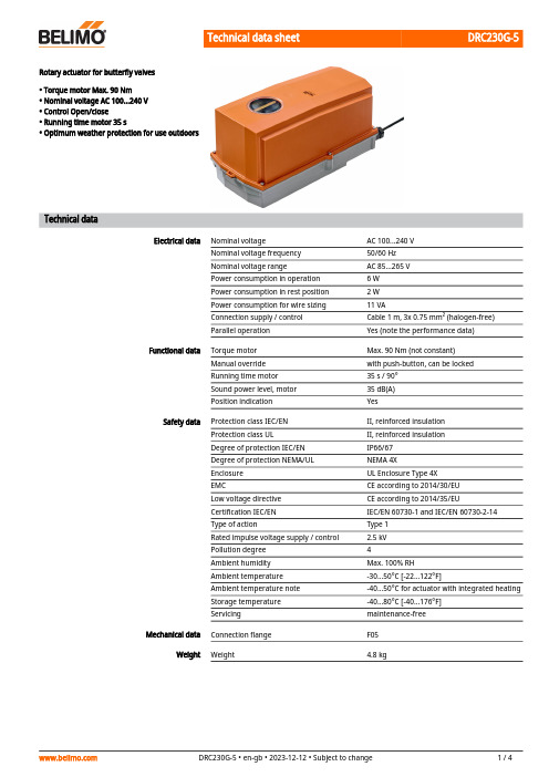
DRC230G-5Rotary actuator for butterfly valves• Torque motor Max. 90 Nm• Nominal voltage AC 100...240 V• Control Open/close• Running time motor 35 s• Optimum weather protection for use outdoorsTechnical dataElectrical data Nominal voltage AC 100...240 VNominal voltage frequency50/60 HzNominal voltage range AC 85...265 VPower consumption in operation 6 WPower consumption in rest position 2 WPower consumption for wire sizing11 VAConnection supply / control Cable 1 m, 3x 0.75 mm² (halogen-free)Parallel operation Yes (note the performance data)Functional data Torque motor Max. 90 Nm (not constant)Manual override with push-button, can be lockedRunning time motor35 s / 90°Sound power level, motor35 dB(A)Position indication YesSafety data Protection class IEC/EN II, reinforced insulationProtection class UL II, reinforced insulationDegree of protection IEC/EN IP66/67Degree of protection NEMA/UL NEMA 4XEnclosure UL Enclosure Type 4XEMC CE according to 2014/30/EULow voltage directive CE according to 2014/35/EUCertification IEC/EN IEC/EN 60730-1 and IEC/EN 60730-2-14Type of action Type 1Rated impulse voltage supply / control 2.5 kVPollution degree4Ambient humidity Max. 100% RHAmbient temperature-30...50°C [-22...122°F]Ambient temperature note-40...50°C for actuator with integrated heatingStorage temperature-40...80°C [-40...176°F]Servicing maintenance-freeMechanical data Connection flange F05Weight Weight 4.8 kgDRC230G-5••••••••••••••Safety notesThis device has been designed for use in stationary heating, ventilation and air-conditioning systems and must not be used outside the specified field of application, especially in aircraft or in any other airborne means of transport.Caution: Power supply voltage!Only authorised specialists may carry out installation. All applicable legal or institutional installation regulations must be complied with during installation.Junction boxes must at least correspond with enclosure IP degree of protection!The cover of the protective housing may be opened for adjustment and servicing. When it is closed afterwards, the housing must seal tight (see installation instructions).The switch for changing the direction of rotation may not be adjusted.The angle of rotation is not permitted to be subjected to mechanical limitation. It is forbidden to alter the mechanical end stops.The device may only be opened at the manufacturer's site. It does not contain any parts that can be replaced or repaired by the user.The device contains electrical and electronic components and must not be disposed of as household refuse. All locally valid regulations and requirements must be observed.The device is not designed for applications where chemical influences (gases, fluids) are present or for utilisation in corrosive environments in general.The actuator may not be used in plenary applications (e.g. suspended ceilings or raised floors).The materials used may be subject to external influences (temperature, pressure,construction fastening, effect of chemical substances, etc.), which cannot be simulated in laboratory tests or field trials. In case of doubt, we definitely recommend that you carry out a test. This information does not imply any legal entitlement. Belimo will not be held liable and will provide no warranty.Flexible metallic cable conduits or threaded cable conduits of equal value are to be used for UL (NEMA) Type 4X applications.When used under high UV loads, e.g. extreme sunlight, the use of flexible metallic or equivalent cable conduits is recommended.Product featuresFields of applicationThe actuator is particularly suitable for utilisation in outdoor applications and is protected against the following weather conditions:- UV radiation - Rain / Snow - Dirt / Dust - Air humidity- Alternating climate / frequent and severe temperature fluctuations (Recommendation: use the actuator with integrated factory-installed heating which can be ordered separately to prevent internal condensation)Simple direct mountingSimple direct mounting on the butterfly valve. The mounting orientation in relation to the butterfly valve can be selected in 90° (angle) increments.Manual overrideManual override with push-button possible (the gear train is disengaged for as long as the button is pressed or remains locked).The housing cover must be removed for manual override.High functional reliabilityThe actuator is overload protected, requires no limit switches and automatically stops when the end stop is reached.DRC230G-5Torque not constantDue to the non-linear torque characteristic the actuator can only be used for butterfly valvesand not for other armatures.Product featuresAccessoriesElectrical accessoriesDescriptionType Auxiliary switch 2x SPDT add-on, grey S2A GR Feedback potentiometer 140 Ω add-on P140A Feedback potentiometer 1 kΩ add-on P1000A Feedback potentiometer 10 kΩ add-onP10000A Options ex works onlyDescriptionType Heater, with adjustable thermostat HT230-MG Heater, with mechanical humidistatHH230-MGWire colours:1 = blue 2 = brown 3 = whiteElectrical installationCaution: Power supply voltage!Wiring diagramsAC 230 V, open/closeDRC230G-5 DimensionsFurther documentation• The complete product range for water applications• Data sheets for butterfly valves• Installation instructions for actuators and/or butterfly valves• General notes for project planning。
使用说明书IES258
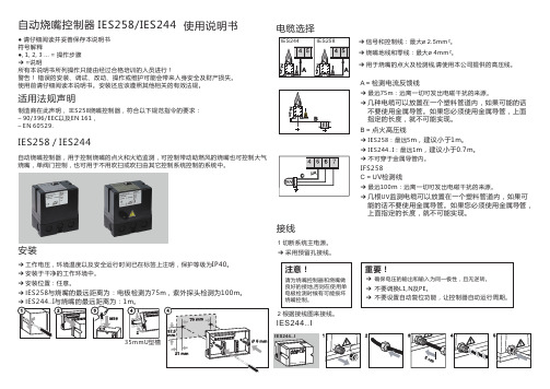
自动烧嘴控制器 IES258/IES244使用说明书● 请仔细阅读并妥善保存本说明书符号解释●, 1, 2, 3 ... = 操作步骤➔ =说明所有本说明书所列操作只能由经过合格培训的人员进行!警告! 错误的安装、调试、改动、操作或维护可能会带来人身安全及财产损失。
使用前请仔细阅读本说明书。
安装还应该遵照其他相关的有效法规。
适用法规声明➔ 信号和控制线:最大ø 2.5mm²。
➔ 烧嘴地线和零线:最大ø 4mm²。
➔用于烧嘴的点火及检测线,请使用本公司提供的高压线。
电缆选择A = 检测电流反馈线➔ IES258:最远5m ,建议小于1m 。
B = 点火高压线➔ 最远75m :远离一切可发出电磁干扰的来源。
➔ 不可穿于金属导管内。
几种电缆可以放置在一个塑料管道内,如果可能的话不要使用金属导管。
如果您必须使用金属导管,上面指定的长度,就不可能实现。
➔ IES244..I :最远1m ,建议小于0.7m 。
➔➔ 最远100m :远离一切可发出电磁干扰的来源。
C = U V 检测线IFS258几根UV 监测电缆可以放置在一个塑料管道内,如果可能的话不要使用金属导管。
如果您必须使用金属导管,上面指定的长度,就不可能实现。
➔接线IES244..I1 切断系统主电源。
➔ 采用预留孔接线。
注意!请为烧嘴控制器和烧嘴做良好的接地,否则在使用单电极检测时候有可能损坏烧嘴控制。
➔ 确保电压的输出和输入为同一极性,且无逆转。
重要!➔ 不要调换L1,N 及PE 。
➔ 不要设置自动复位功能,让控制器自动运行周期。
2 根据接线图来接线。
IES258 / IES244安装自动烧嘴控制器,用于控制烧嘴的点火和火焰监测,可控制带动助燃风的烧嘴也可控制大气烧嘴,单阀门控制,也可用于不用吹扫或吹扫由其它控制系统控制的系统中。
➔ 安装于干净的工作环境中。
➔ 工作电压,环境温度以及安全运行时间已在标签上注明,保护等级为IP40。
佛山市禅城区星火电子电器厂 CHL系列商用燃气炉安全自动控制器 说明书

商用商用燃气燃气燃气炉炉安全自动安全自动控制器控制器(CHL 系列)使用说明书佛山市禅城区星火电子电器厂地址:佛山市禅城区轻工三路16号 电话:0757-******** 82107005 传真:0757-******** 邮编:528000 E-mail:xhdzdq@一、简介本商用燃气炉自动点火及熄火保护控制器(以下简称控制器)专用于商用燃气炉的炒炉、蒸饭柜、蒸饭车、大镬炉、汤炉、矮汤炉等大功率燃气设备的自动控制。
该控制器采用可调节燃气流量、工作寿命长、高可靠并可通过大流量燃气的转子式燃气调节阀;控制开关为磁控开关,只要转动手动燃气阀的手柄,即可自动点火;点火则摒弃了以往一直使用的使用母火(火种)引燃的方式,采用大功率高频高压电流产生的电火焰点火,炉膛中高速鼓风的气流及燃气压力波动均不会影响点火效果,做到百点百着;点火棒是用高温抗氧化钢,可耐1200℃高温,使用时间超过2000小时以上,并且采用直接检测燃烧火焰的高灵敏火焰检测,当主火意外熄灭时,在1秒内安全切断燃气。
由于本控制器采用了多项已开发多时的成熟技术,可以达到操作方便,工作可靠,不受商用燃气炉燃气压力波动大、燃气和空气混合比波动大以及工作环境高温潮湿、炉膛中有水淋、杂物跌落等恶劣条件的影响。
本控制器把控制器与燃气转子式电磁阀组装成一体;进出气接头分别用四颗、六颗螺钉与电磁阀连接,减少了因应力造成漏气的现象发生;开关引线直接从控制器外壳引出,并用护套线连成一体,开关是磁控式,没有机械动作结构,经久耐用;只需将点火及探火两根线与点火棒用螺钉连接;一经接上AC 220V 电源,控制器即可工作。
控制器外壳采用高级工程塑料,耐温防淋。
因而该控制器外形结构简洁,安装方便简单,而且维护方便。
二、型号类别示例:a. CHL-BO1A厨房用炉控制器,自动点火及熄火保护功能(液化气、天然气通用); b. CHL-BO1B厨房用炉控制器,自动点火及熄火保护加上离镬火力控制功能;三、特性及功能说明控制器电路采用电脑芯片控制,把高频高压火焰点火器,火焰离子检测器电路与转子式燃气电磁阀组装在优质工程塑料注塑成型的外壳内,外表面只留燃气进出气接口、带护套的磁控开关引线、电源线及点火、探火线,磁控开关由护套与外壳连成一体,探火线、点火线的安装方式有两种安装方式。
德瑞摩(DERHMO)电动执行机构调试步骤

德瑞摩(DERHMO)电动执行机构调试步骤�DREHMO(德国)(SFEUANFRIEBE/ACFUATORS)执行器调试操作步骤�按功能键,显示出主菜单,在主菜单中按↑、↓键选择Learn Mode(学习方式)菜单,按功能键进入菜单。
�选择Parameters(方向),在众菜单中选择Valve(阀门),在Valve(阀门)中选择菜单Closing Direction(设定方向):�在Closing Direction中根据阀门类型选择Couterlowise Open(逆时针开)或Clowise Open(顺时针开)开方向。
�继续选择Valve(阀门)菜单中的Final Position Linmit Sw(最终位置设定)菜单,在此菜单中选择适合阀门跳断的类型。
�按设置键进入Local,Learn moba连续按↓键选择�按Esc键退出至Learn Mode(学习模式)菜单下�连续按↓进入Change finol positions(改变阀门位置)�按确认键进入Clear position close(显示位置关)�连续按↓进入Set position close(预备关设定)�按确认键进入sition close0%===========100%�然后按↓↑键操作阀门要求关的实际位置,当阀门实际动作位置符合要求时,按确认键。
�Oper操作步骤同上。
�按Esc键退出至主菜单,选择Local(就地)或Remote(远控)模式,设定完成。
�接线图如下:�X2端子排:PE2(U相)、4(V相)、6(W相)�X1端子排:20与17短接、21与16短接�X1端子排:5(COM)、6(开到位)、7(关到位)�X1端子排:13(COM)、14(故障常闭)、15(故障常开)根据情况设定。
�X1端子排:23(+)、24(-)为4~20mA反馈信号。
�X1端子排:25(+)、26(-)为4~20mA指令信号。
�X1端子排:1(OV)、2(停)、3(开指令)、4(关指令)根据情况设定。
Hobart HRW220 HRO220 HRO220P HRW220P 烤肉机替代零件目录说明书
CA T ALOG OFREPLACEMENT P ARTSROTISSERIE OVENS WITH WARMERMODELHRW220P ML-114904HRO220P ML-114903HRW220ML-114641HRO220ML-114635A p r o d u c t o f H OB A R TC O R P O R A T I O N701S.R ID GE A V E N U E T R O Y,O H I O45374-0001HRO/HRW220 SERIES REPLACEMENT PARTS-33677 R e v . A (J a n . 2001)HRO/HRW220FORM 33677 Rev. ATABLE OF CONTENTS WITH PL NUMBERSPAGEDESCRIPTION NONE 2TABLE OF CONTENTS PL-523073PRODUCT ILLUSTRATION PL-523085DOOR ASSEMBLYPL-523097CONTROL PANEL (HRO220/HRW220)PL-535329CONTROL PANEL (HRO220P/HRW220P)PL-5353311ROTISSERIE PL-5231113BLOWER PL-5520215OVEN PL-5352517WARMERPL-5231419RACKS & TRAYS (WARMER)PL-5231520ACCESSORIESHRO/HRW220 SERIES REPLACEMENT PARTSF-33677 Rev. A (Jan. 2001)PL-52307HRO220HRO220WARMER = HRW220HRO/HRW220 SERIES REPLACEMENT PARTS-33677 R e v . A (J a n . 2001)DOOR ASSEMBLYPL-52308HRO/HRW220 SERIES REPLACEMENT PARTSDOOR ASSEMBLYILLUS.PART OF PART AMT.PL-52308100-422905-00047Angle – Hinge Pin (Use with Service Side Door) (1)200-422905-00057Hinge Pin Assy (1)300-356940Bracket – Hinge Door (2)400-422905-00046Glass – Door (Service Side) (1)500-422905-00056Glass – Double Door (1)600-422905-00087Bushing – Distance 8 mm (2)700-422905-00049Washer – M6 (4)800-357568Washer – Spring Toothed M6 (4)900-358580Cap Nut – M5 (4)1000-357553-00057Lockwasher – M5 (4)1100-357553-00073Washer – M5 (10)1200-422905-00048Holder – Block Magnet (1)1300-360128Magnet – Door (7)1400-356850Magnet – Door (Use with Service Side Door) (8)1500-357566Self-Tapping Screw 4.8 x 50 mm Flat Hd (2)1600-357752Plug – Door Handle (2)1700-356851Cap – Handle End (2)1800-422905-00086Handle – Bar (1)1900-422905-00045Frame – Door Assy. (Service Side) (1)2000-422905-00053Door – Outer (1)2100-422905-00054Door – Inner Assy (1)2200-422905-00055Clamp – Glass Holder (2)2300-357114Bushing – Door (HRW220) (8)2400-422905-00059Screw – M5 x 8 (4)00-422905-00027Door – Service Side (Incls. items 1,3,4,6 thru 12,14,15,17,18 & 19).....................AR00-422905-00028Door – Customer Side (Incls. items 2,5,12,13,16,20,21,22 & 25)..........................ARF-33677 Rev. A (Jan. 2001)HRO/HRW220 SERIES REPLACEMENT PARTS-33677 R e v . A (J a n . 2001)CONTROL PANEL (HRO220/HRW220)HRO/HRW220 SERIES REPLACEMENT PARTSCONTROL PANEL (HRO220/HRW220)ILLUS.PART OF PART AMT.PL-52309100-360036Thermometer (Warmer) (1)200-360145Thermostat (Oven) (1)300-356946Sensor – Temperature (Oven) (1)400-422905-00022Bracket (1)500-356878Switch – Rotary (Warmer) (1)600-359460-00033Bracket – Thermostat (Warmer) (1)700-357196Thermostat (Warmer) (1)800-356841Block – Terminal (Warmer) (1)900-359460-00057Capacitor (1.5 mf) (Warmer) (3)1000-359460-00019Panel – Electrical Component (1)1100-422905-00075Control Panel Assy. (Warmer) (1)1200-356833Knob (1)1300-422905-00015Control Panel Assy. (Oven) (1)1400-422905-00014List Assy (1)1500-356833Knob (3)1600-359460-00048Ring – Sealing.........................................................................................................AR1700-359460-00060Timer – Digital Display (Oven) (1)1800-359460-00042Clip Timer Display (Oven) (1)1900-360145Thermostat (Hi-Limit) (1)F-33677 Rev. A (Jan. 2001)HRO/HRW220 SERIES REPLACEMENT PARTS-33677 R e v . A (J a n . 2001)CONTROL PANEL (HRO220P/HRW220P)HRO/HRW220 SERIES REPLACEMENT PARTSCONTROL PANEL (HRO220P/HRW220P)ILLUS.PART OF PART AMT.PL-53532100-359758-00007Display (1)200-422905-00095Cover – Display (1)300-422905-00014List Assy (1)400-422905-00093Panel (HRO220P) (1)500-360036Thermometer (Warmer) (1)600-356946Sensor – Temperature (Oven) (1)700-422905-00022Bracket (1)800-359460-00033Bracket – Thermostat (Warmer) (1)900-356839Switch – Main (On/Off) (Warmer) (1)1000-359460-00019Panel – Electrical Component (1)1100-357196Thermostat (Warmer) (1)1200-357553-00035Block – Terminal (Warmer) (1)1300-360151Relay (1)1400-356842Bracket – Terminal Block Mounting (1)1500-359460-00057Capacitor (1.5 mf) (Warmer) (2)1600-360201Capacitor (2.5 mf) (Warmer) (1)1700-356841Block – Terminal (Warmer) (1)1800-360145Thermostat (1)1900-358521-00046Strain – Relief (2)2000-360280Plate – Ground (1)2100-357553-00056Nut – M5 (1)2200-357553-00058Bolt – M5 x 16 (1)2300-358712-00002Block – Terminal “4,5,6” (1)2400-358713Screw – M4 x 20 (2)2500-358712-00001Block – Terminal “1,2,3” (1)2600-358713Screw – M4 x 20 (2)2700-422905-00075Control Panel Assy. (Warmer) (1)2800-356840Holder – Fuse (2)2900-359460-00083Fuse (1)3000-358713Screw – M4 x 20 (4)3100-357553-00152Capacitor (1.5 mf) (1)3200-360143Bushing (2)3300-359758-00011Holder – Meat Probe (1)3400-422905-00096Plate – Mounting (1)3500-359460-00048Ring – Sealing (2)3600-356833Knob (2)3700-422905-00013Overlay (Use with item 4) (1)3800-360145Thermostat (1)F-33677 Rev. A (Jan. 2001)HRO/HRW220 SERIES REPLACEMENT PARTS-33677 R e v . A (J a n . 2001)ROTISSERIEROTISSERIEILLUS.PART OF PART AMT.PL-53533100-422905-00010Element – Heating (2000 Watts Each Unit) (240 V.) (2)200-422905-00009Element – Heating (2000 Watts Each Unit) (208 V.) (2)300-422905-00026Plate – Lamp Holder with Air Slots (1)400-359460-00066Strip – Lamp Holder Mounting (2)500-422905-00006Strip – Mounting (2)600-359460-00013Protector – Quartz Lamp (2)700-360152Fork – Meat (5)800-360152-00003Spit (Rotisserie) (Set of 5 Meat Forks) (1)900-425900-00301Disc – Rotor (3 mm) (Universal) (5 Spit) (2)1000-360134Shaft (1)1100-360137Seal – Ring (1)1200-422905-00020Motor – Drive System (1)1300-359460-00041Guard – Fan (1)1400-360248Blade – Fan (1)1500-422905-00021Plate – Protector (1)1600-422905-00019Support – Motor (1)1700-425900-00001Rotor Assy. (Incls. items 9,10, & 18 thru 21) (1)1800-360132Disc – Stud (1)1900-425900-00302Bolt – M6 x 20 SST (6)2000-513886Sealer......................................................................................................................AR21SC-117-32Set Screw – M8 x 1.25 x 16 mm (4)2200-422905-00023Support – Bearing (1)2300-360156Holder – Quartz Lamp (4)2400-360155Lamp – Quartz (2)2500-360129Holder – Quartz Lamp Base (4)F-33677 Rev. A (Jan. 2001)-33677 R e v . A (J a n . 2001)BLOWERBLOWERILLUS.PART OF PART AMT.PL-52311100-422905-00008Blade – Fan.............................................................................................................AR200-359460-00025Blower (W/Fan Blade) (1)300-422905-00007Fan – Mtg (1)F-33677 Rev. A (Jan. 2001)-33677 R e v . A (J a n . 2001)OVENOVENILLUS.PART OF PART AMT.PL-55202100-422905-00032Panel – Outer (L.H.) (Oven) (1)200-422905-00064Panel – Outer (L.H.) (Oven & Warmer) (1)300-422905-00004Plate – Reinforcement (L.H.) (1)400-422905-00005Plate Assy. (L.H.) (1)500-422905-00029Plate Assy. (R.H.) (1)600-422905-00030Top Assy (1)700-422905-00001Panel – Inner Side (1)800-422905-00080Plate – Bottom (Warmer) (1)900-422905-00067Panel – Inner Warmer Side (1)1000-422905-00062Panel – Lower Front (Customer Side) (Warmer) (1)1100-422905-00013Panel – Lower Front (Customer Side) (1)1200-422905-00003Reinforcement – Profile (1)1300-422905-00033Panel – Outer (R.H.) (Oven) (1)1400-422905-00065Panel – Outer (R.H.) (Warmer) (1)1500-422905-00016Panel – Customer Side (1)1600-356840Holder – Fuse (HRO220P/HRW220P) (1)1700-422905-00097Fuse (HRO220P/HRW220P) (1)1800-422905-00041Tray – Spark (2)1900-422905-00094Panel – Mtg. (HRO220P/HRW220P) (1)2000-422905-00002Leg – Rubber (Oven) (4)2100-360207Screw – Wing (1)2200-360205Gasket – Seat (1)2300-359460-00054Set Screw – Grease Sealing (1)2400-422905-00024Tray Assy (1)2500-422905-00063Tray Holder Assy. (Warmer) (1)2600-422905-00025Plate – Grease (2)2700-360206Gasket – Drain (1)2800-359460-00055Washer – Grease Sealing (2)2900-359460-00056Bolt – Grease Sealing (1)3000-359758-00012Probe – Meat (HRO220P/HRW220P) (1)3100-422905-00061Panel – Lower Front (Operator’s Side) (Warmer) (1)3200-422905-00012Panel – Lower Front (SST) (1)3300-422905-00092Panel – Lower Front (HRO220P/HRW220P) (1)3400-422905-00003Reinforcement – Profile (1)3500-422905-00068Reinforcement – Lateral Top Left (Oven) (1)3600-422905-00069Reinforcement – Lateral Top Right (Warmer) (1)00-359460-00058Strain Relief (1)00-422905-00011Reinforcement – Hinge (4)F-33677 Rev. A (Jan. 2001)-33677 R e v . A (J a n . 2001)WARMERWARMERILLUS.PART OF PART AMT.PL-53525100-360143Bushing (2)200-422905-00079Nozzle – Blow (1)300-359460-00025Blower (W/Fan Blade) (1)400-422905-00072Plate – Fan Mtg (1)500-360244Caster – W/Lock (2)600-422905-00060Caster – W/O Lock (2)700-422905-00083Plate – Wheel Mtg (1)800-422905-00082Plate – Backup (2)900-360047Element – Heating (1)1000-360112Bracket – Heating Element (1)1100-356944Plate – Mounting (1)1200-422905-00076Plate – Cover (1)1300-422905-00012Panel – Lower Front (SST) (1)1400-360446Lamp – Halotherm (200 W.) (1)1500-360240Holder – Lamp (2)1600-356861Lamp – Reflector (Halogen) (1)1700-422905-00078Plate – Ceiling (1)1800-359758-00008Cover – Controls Circuit Board (Use with item 20) (1)1900-359758-00011Receptacle – Meat Probe (HRO220P) (1)2000-359460-00061Timer – Control (12 Hr.) (1)2100-422905-00105Fuse – 63 MA (PC Board) (1)2200-422905-00100Controls – Circuit Board (208 V.)(HRO220P) (1)2300-359758-00014Ribbon – Cable (HRO220P) (1)F-33677 Rev. A (Jan. 2001)-33677 R e v . A (J a n . 2001)RACKS & TRAYS (WARMER)RACKS & TRAYS (WARMER)ILLUS.PART OF PART AMT.PL-52314100-360136Spacer – Fan Guard (4)200-422905-00071Fan Cover – Warmer Assy (1)300-422905-00080Plate – Bottom (Warmer) (1)400-422905-00081Rack – Stainless Steel Wire (3)500-422905-00070Rack Slide Assy (1)F-33677 Rev. A (Jan. 2001)ACCESSORIESILLUS.PART NO.NAME OF PARTAMT.PL-52315100-360298Sleeve – Spit .............................................................................................................1200-360299Fork – Spit.. (23)00-360300Shaft – Spit ...............................................................................................................1400-360279Split – Turkey Assy. (Incls. items 1,2,3 & 5)..............................................................1500-360297Screw – Wing (M5)....................................................................................................3600-360385Glide Pin ...................................................................................................................17SL-005-08Spring – Loading.......................................................................................................28NS-047-13Nut – M6 x 1.0 Hex SST ...........................................................................................2900-360383Plate – Baking...........................................................................................................11000-360278Plate – Baking Assy. (Incls. items 6 thru 9 & 11 thru 13)..........................................11100-360384Drag Pin ....................................................................................................................112SL-005-08Spring – Loading. (213)NS-047-13Nut – M6 x 1.0 Hex SST ...........................................................................................200-360277Basket .......................................................................................................................100-357896Rack – Chicken (Three-Position)..............................................................................100-359579Spit-V (Short) (Single-Position) (1)。
瑞德 Silhouette II 80.0% - 81.7% AFUE 向上流 水平燃气炉 说明书
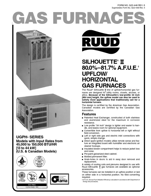
FORM NO. G22-448 REV. 6Supersedes Form No. G22-448 Rev. 5 GAS FURNACESSILHOUETTE®II80.0%–81.7% A.F.U.E.UPFLOW/HORIZONTALGAS FURNACESThe Ruud®Silhouette II line of upflow/horizontal gas fur-naces are designed for utility rooms, closets, alcoves, orattics. Because of the Silhouette’s low-profile 34 inch[864 mm] height, the upflow model can also be used to UGPH- SERIESSTANDARD EQUIPMENTCompletely assembled and wired; induced draft blower; pressure switch; redundant main gas control; blower compartment door safety switch; solid state time on/time off blower control; limit control; manual shut-off valve, pressure regulator for natural and L.P. (propane) gas; transformer; direct drive multi-speed blower motor. Furnaces are equipped with cooling/heating relay and transformer (40VA) ready for air conditioning applications. (Please note: a thermostat is not included as standard equipment.) Flame sensor diagnostics;on-board twinning options;fused transformer (secondary), 3rd speed fan option for continuous fan; common heat/cool terminal. OPTIONAL EQUIPMENTSide filter frame assembly. Return air cabinet for all sizes. (See Page 6) NOTE:Furnace is not listed for use with fuels other than natural or L.P.(propane) gas.WARNING THIS FURNACE IS NOT APPROVED OR RECOMMENDEDFOR USE IN MOBILE HOMESDirect Spark Ignitorwith Remote SenseIn-Shot BurnersDraft Inducer MotorIntegratedFurnaceControlHeat ExchangerMolded Permanent FilterThe complete terms of limited and other warranties are available at oursales office, or through local installer.All models can be converted by a qualified Ruud distributor or local servicedealer to use L.P. (propane) gas without changing burners. Factory approvedkits must be used to convert from natural to L.P. (propane) gas and may beordered as optional accessories from a Ruud parts distributor.For L.P. (propane) operation, refer to Conversion Kit Index Form No. 92-21519-52for U.S. models and Form No. 92-21519-53 for Canadian models.23BEFORE PURCHASING THIS APPLIANCE, READ IMPORTANT ENERGY COST AND EFFICIENCY INFORMATION AVAILABLE FROM YOUR RETAILER.PHYSICAL DATA AND SPECIFICATIONSMODEL IDENTIFICATION—UPFLOW MODELS[] Designates Metric ConversionsU G PH—07EA UERRuudGas Upflow/Design Heating Input Designation Variations Blower Heating & Cooling Fuel Type U =11 x 6[279 x 152 mm]M =11 x 7[279 x 178 mm]R =11 x 10[279 x 254 mm]S =500-1200 CFM[236-566 L/s]E =1100-1330 CFM[519-628 L/s]G =1450-1750 CFM[684-826 L/s]J =1800-2075 CFM[850-979 L/s]FurnaceHorizontal SeriesElectric Ignition 04E 05E 06E 07E 10E 12E 15EA =Std.Cabinet B =WideCabinetDesignation Designation R =Natural Gas,U.S. Standard Furnace A =Natural Gas,Canadian Standard FurnaceInput BTU/HR 45,000 [13 kW]50,000 [15 kW]67,500 [20 kW]75,000 [22 kW]100,000 [29 kW]125,000 [37 kW]150,000 [44 kW]NO x Model 04N 05N 06N 07N 10N 12N 15NIn accordance with D.O.E. test procedures.See Conversion Kit Index Form No. 92-21519-52 for U.S. models and Form No. 92-21519-53 for Canadian models for high altitude derate.*Data references Canadian Models only.4May be 0" [0 mm] with type B vent.May be 1" [25 mm] with type B vent.Furnaces must be vented in accordance with ANSI Z21.47-1993 • CAN/CGA-2.3-M93 venting table guidelines and in accordance with local codes. [] Designates Metric ConversionsUPFLOW DIMENSIONS5May be 0" [0 mm] with type B vent. May be 1" [25 mm] with type B vent.Furnaces must be vented in accordance with ANSI Z21.47-1993 • CAN/CGA-2.3-M93 venting table guidelines and in accordance with local codes.[] Designates Metric ConversionsHORIZONTAL DIMENSIONSWARNINGTHIS FURNACE IS NOT APPROVED OR RECOMMENDED FOR INSTALLATION ON ITS BACK, WITH ACCESS DOORSFACING UPWARDS.ACCESSORIES—UPFLOW PLENUM DATA FOR “A” COILSPlenum adapters are required in some instances for use on upflow applicationsOPTION CODE FOR HIGH ALTITUDE: US-277Canada-298(U.S. Models—Kit packaged with furnace.Requires field installation.)OPTION CODE FOR SOLID BOTTOM: US-263(U.S. Models—Kit packaged with furnace.Requires field installation.)EXTERNAL BOTTOM FILTER RACK:RXGF-CBFilters shipped with furnace may be used or a suitable 1" [25.4 mm] filter.*Designates “E” or “N”.RXPF-F01 and F02FOSSIL FUEL KITS are for use with Ruud Heat Pumpsand Silhouette II warm air furnaces. The RXPF-F02 meets TVA requirements.ACCESSORY RETURNAIR CABINETSReturn Air Cabinets may beinstalled on rear or either sideapplication except RXGR-C24B(side application must beon side opposite gas andelectrical connections).THE RXGR-C24B MAY ONLY BE INSTALLEDON REAR AND LEFT SIDES.WARNING: IMPORTANT NOTICEA SOLID METAL BASE PLATE (SEE TABLE) MUST BE IN PLACE WHEN THE FURNACEIS INSTALLED WITH SIDE OR REAR AIR RETURN DUCTS. FAILURE TO INSTALL A BASE PLATE COULD CAUSE PRODUCTS OF COMBUSTION TO BE CIRCULATED INTO THE LIVING SPACE AND CREATE POTENTIALLY HAZARDOUS CONDITIONS. SOLID BOTTOM IS AVAILABLE FACTORY INSTALLED WITH OPTION CODE 263.FURNACE BASEWIDTHSOLID BOTTOM BASEPLATE SIZE IN. [mm]KIT NO.PLATE NO.IN. [mm] 14[356]RXGB-D14AE-61874-01115/8x 239/16[295 x 598] 171/2[445]RXGB-D17AE-61874-02151/8x 239/16[384 x 598] 21[533]RXGB-D21AE-61874-03185/8x 239/16[473 x 598] 241/2[622]RXGB-D24AE-61874-04255/8x 239/16[651 x 598][]Designates Metric Conversions6**Not to be used as a heating speed.Data compiled with factory filters installed.[]Designates Metric Conversions7“In keeping with its policy of continuous progress and product improvement, Ruud reserves the right to make changes without notice.”PRINTED IN U.S.A.3-99 DC FORM NO. G22-448 REV. 6Supersedes Form No. G22-448 Rev. 5。
SDC Security EH系列磁门扳机说明书

EH10 Door Holder, Flush Mount EH20 Door Holder, Semi-Flush Mount EH30 Door Holder, Surface Mount EH40 Door Holder, Floor Mount SingleEH42 Door Holder, Floor Mount DoubleMODELS• Door release and close upon power loss or fire life safety system activation • Low power consumption• Field selectable high holding force• Dual AC/DC voltage configurations • Screw terminal block input connections • Self-aligning catch plate• Adjustable magnet centerlineSTANDARD FEATURESSDC’s EH series magnetic door holders are designed to hold doors open and release the door by remote switch or fire life safety command center activation. Primary application includes holding and releasing of fire rated doors that are required to provide a barrier for fire and smoke in an emergency or the convenience of door closure by remote control.Choice of 25, 30, 35 or 40lbs holding force determined by units specified voltage. Reduced power supply requirements and energy costs due to low power consumption (15mA to 40mA). Field selectable high holding force comes standard, reducing stock or need to special order high holding force. Screw terminal block input connections for simple and neat wiring. Innovative installation eliminates the need for secondary alignment adjustments. Ball pivot assembly enables full plate contact and holding force. Optional adjustable rod compensate for extreme misalignment up to four inches. Slotted mounting holes enable adjustment of magnet centerline.EH101224A EH1024120A EH1024220A EH301224A EH3024120A EH3024220AEH201224A EH2024120A EH2024220A EH SeriesElectromagnetic DoorHolder & Releasing DevicesEH10EH20EH30EH40EH42ConstructionZinc AlloyZinc AlloyZinc AlloyZinc AlloyZinc AlloyMount FlushSemi-FlushSurfaceFloor Floor Projection211/32”31/16”45/8”5”95/8”Fasteners Hardware Package,Mounting BracketHardware Package,Mounting BracketHardware Package,Mounting BracketHardware Package,Mounting BracketHardware Package,Mounting Bracket CoilSingleSingleSingleSingleDoubleSPECIFICATIONSFOLLOW STEPS FOR ORDERINGDesignates optional stepHOW TO ORDERPERFORMANCE DATAHIGH HOLDING FORCE / SPECIAL APPLICATIONS ** T o obtain performance values in table above, apply higher listed voltage to lower voltage terminals (C&L). This can only be applied to the above listed 1224 and 24120 configurations.UL 864 Control Units and Accessories for Fire Alarm Systems ULC/ORD-C228 Door Closers and Holders CSFM Listed 3550-0324:0110CERTIFICATIONSRELATED PRODUCTSEXTENSION RODS *Extensions rod(s) may be required to ensure properinstallation by providing increased reach for the armature catch plate.EHR02A 1/2” Extension Rod, Chrome Powder Coat EHR02B 1/2” Extension Rod, Black Powder Coat EHR1A 1” Extension Rod, Chrome Powder Coat EHR1B 1” Extension Rod, Black Powder Coat EHR15A 11/2” Extension Rod, Chrome Powder Coat EHR15B 11/2” Extension Rod, Black Powder Coat EHR2A 2” Extension Rod, Chrome Powder Coat EHR2B 2” Extension Rod, Black Powder Coat EHR3A 3” Extension Rod, Chrome Powder Coat EHR3B 3” Extension Rod, Black Powder Coat EHR4A 4” Extension Rod, Chrome Powder Coat EHR4B 4” Extension Rod, Black Powder Coat EHR5A 5” Extension Rod, Chrome Powder CoatEHR5B 5” Extension Rod, Black Powder Coat ADJUSTABLE EXTENSION RODS *Adjustable extension rods provide increased operational alignment where needed to ensure the best door holder operation and performance.EHRA15A 11/2” Adjustable Extension Rod, Chrome Powder Coat EHRA15B 11/2” Adjustable Extension Rod, Black Powder Coat EHRA4A 4” Adjustable Extension Rod, Chrome Powder Coat EHRA4B 4” Adjustable Extension Rod, Black Powder Coat* See installation instructions for guidance on determining extension rod and adjustable extension rod length.REPLACEMENT PARTSEHBBA 225/32” x 47/8” 11/2” Surface Back Box, Chrome Powder Coat.EHBBB 225/32” x 47/8” 11/2” Surface Back Box, Black Powder Coat.EHCPA Catch Plate, Chrome Powder Coat.EHCPB Catch Plate, Black Powder Coat.EHSBAA Catch Plate Assembly, Chrome Powder Coat.EHSBAB Catch Plate Assembly, Black Powder Coat.INSTALLATION TOOLSAttach drill fixtures to the door for quick and accurate hole locations. Utilize extension wrenches to tighten extension rods to catch plate assemblies.EHW Extension Wrench。
艾顿 Moeller 系列 MSC-R 转向启动器 产品说明书

Eaton 283190Eaton Moeller® series MSC-R Reversing starter, 380 V 400 V 415V: 0.06 kW, Ir= 0.16 - 0.25 A, 24 V DC, DC voltage MSC-R-0,25-M7(24VDC)Especificaciones generalesEaton Moeller® series MSC-R Reversingstarter2831904015082831905185 mm95 mm90 mm 1 kgCSA File No.: 012528IEC/EN 60947-4-1UL File No.: E123500CSACSA Class No.: 3211-24ULUL 508 (on request)CEUL60947-4-1ACSA-C22.2 No. 14-10UL Category Control No.: NKJH CSA-C22.2 No. 14 (on request)MSC-R-0,25-M7(24VDC)Product Name Catalog NumberEANProduct Length/Depth Product Height Product Width Product Weight Certifications Model CodeShort-circuit releaseTemperature compensated overload protection CLASS 10 AScrew terminalsNo2IP20NEMA OtherReversing starterDIN rail0.16 A0.25 AIII36000 V ACAlso motors with efficiency class IE3 Starter with Bi-Metal releaseDCFitted with: Functions ClassConnectionConnection to SmartWire-DTCoordination typeDegree of protectionModelMounting methodNumber of auxiliary contacts (normally closed contacts) Number of auxiliary contacts (normally open contacts) Overload release current setting - minOverload release current setting - maxOvervoltage categoryPollution degreeRated impulse withstand voltage (Uimp)Suitable forTypeVoltage typeMax. 2000 m -25 °C55 °C 0.21 A0.25 A0.04 kW0.06 kW230 - 415 V AC1 A, 250 V DC, (UL/CSA)15 A, 600 V AC, (UL/CSA)A600, AC operated (UL/CSA) P300, DC operated (UL/CSA)50000 A 3.9 A 3 W 0 V 0 V 0 V 0 V 24 V 24 VAltitudeAmbient operating temperature - min Ambient operating temperature - max Rated operational current (Ie)Rated operational current (Ie) at AC-3, 380 V, 400 V, 415 V Rated operational power at AC-3, 220/230 V, 50 HzRated operational power at AC-3, 380/400 V, 50 HzRated operational voltageSwitching capacity (auxiliary contacts, general use) Switching capacity (auxiliary contacts, pilot duty)Rated conditional short-circuit current (Iq), type 2, 380 V, 400 V, 415 VShort-circuit release (Irm) - max Power consumption (sealing) at DCRated control supply voltage (Us) at AC, 50 Hz - min Rated control supply voltage (Us) at AC, 50 Hz - max Rated control supply voltage (Us) at AC, 60 Hz - min Rated control supply voltage (Us) at AC, 60 Hz - max Rated control supply voltage (Us) at DC - minRated control supply voltage (Us) at DC - max5.7 W0 W1.9 W0.25 A2.6 WMeets the product standard's requirements.Meets the product standard's requirements.Meets the product standard's requirements.Meets the product standard's requirements.Meets the product standard's requirements.Does not apply, since the entire switchgear needs to be evaluated.Does not apply, since the entire switchgear needs to be evaluated.Meets the product standard's requirements.Does not apply, since the entire switchgear needs to be evaluated.Meets the product standard's requirements.Does not apply, since the entire switchgear needs to be evaluated.DA-DC-00004910.pdfDA-DC-00004878.pdfeaton-manual-motor-starters-starter-msc-r-reversing-starter-dimensions.epseaton-manual-motor-starters-mounting-msc-r-reversing-starter-3d-drawing.epsDA-CE-ETN.MSC-R-0,25-M7(24VDC)eaton-manual-motor-starters-starter-msc-r-reversing-starter-wiring-diagram.epsSimple, flexible and safe! Distribution system for motor-starter combinationsIL03402006ZDA-CD-msc_r_bg1DA-CS-msc_r_bg1Equipment heat dissipation, current-dependent PvidHeat dissipation capacity PdissHeat dissipation per pole, current-dependent PvidRated operational current for specified heat dissipation (In) Static heat dissipation, non-current-dependent Pvs10.2.2 Corrosion resistance10.2.3.1 Verification of thermal stability of enclosures10.2.3.2 Verification of resistance of insulating materials to normal heat10.2.3.3 Resist. of insul. mat. to abnormal heat/fire by internal elect. effects10.2.4 Resistance to ultra-violet (UV) radiation10.2.5 Lifting10.2.6 Mechanical impact10.2.7 Inscriptions10.3 Degree of protection of assemblies10.4 Clearances and creepage distances10.5 Protection against electric shock10.6 Incorporation of switching devices and components Declarations of conformity DibujoseCAD modelEsquemas eléctricos FolletosInstrucciones de montaje mCAD modelEaton Corporation plc Eaton House30 Pembroke Road Dublin 4, Ireland © 2023 Eaton. All Rights Reserved. Eaton is a registered trademark.All other trademarks areproperty of their respectiveowners./socialmediaDoes not apply, since the entire switchgear needs to be evaluated.Is the panel builder's responsibility.Is the panel builder's responsibility.Is the panel builder's responsibility.Is the panel builder's responsibility.Is the panel builder's responsibility.The panel builder is responsible for the temperature rise calculation. Eaton will provide heat dissipation data for the devices.Is the panel builder's responsibility. The specifications for the switchgear must be observed.Is the panel builder's responsibility. The specifications for the switchgear must be observed.The device meets the requirements, provided the information in the instruction leaflet (IL) is observed.10.7 Internal electrical circuits and connections 10.8 Connections for external conductors 10.9.2 Power-frequency electric strength 10.9.3 Impulse withstand voltage 10.9.4 Testing of enclosures made of insulating material 10.10 Temperature rise10.11 Short-circuit rating10.12 Electromagnetic compatibility10.13 Mechanical function。
IES258

IES258烧嘴控制器IES258 用于控制烧嘴的点火和火焰监测, 可控制带助燃风的烧嘴也可控制大气烧嘴, 单阀门控制, 也可用于不用吹扫或吹扫由其它控制系统控制的系统中。
功能:● 可控制任何功率燃气烧嘴的点火(点火功率不大于350KW )● 可采用电离式火焰监测或紫外线UV监测● 点火和监测可能过一根电极完成● 火焰熄灭后锁定报警● 火线零线端子不可互换● 有正常和故障两组输出端子技术参数:● 工作电压:220V,功率19VA● 火焰检测电流可在2~20μA之间调节● 高压点火电缆最好<1米● 电缆长度:电离监测方式最长75米,UV监测方式最长100米● 报警灯亮后才可复位● 输出电流:每个输出最大2A,总电流最大2.5A● 熔断丝: 3.15A慢熔型符合IEC127-2/5● 使用寿命:10万以上,如采用单电极270000 次以上● 环境温度:-20~60℃,不允许有任何的冷凝执行标准:● 欧洲CE 认证,符合欧洲燃气应用规范应用举例:图1:助燃风烧嘴(≤ 350kW)控制模式:开/闭。
燃气和空气电磁阀同时打开,烧嘴的点火和 火焰监测由单电极完成,火焰故障熄灭后立刻锁定报警。
图2:助燃风烧嘴(≤350kW)控制模式:连续控制。
空气蝶阀开到点火位置,烧嘴在低负荷下 点燃,然后由温控仪表控制空气蝶阀的开度,调节烧嘴功率,火 焰故、障熄灭后可重新点火或锁定报警。
图3:助燃风烧嘴(>350kW)控制模式:大火/小火或大火/小火/关闭。
烧嘴在小火状态下点燃,等操作信号传输到PLC后,PLC会打开空气阀,将烧嘴转换成大火 状态,火焰故障熄灭后可重新点火或锁定报警。
火焰检测方式:IES 258 烧嘴控制器可以采用电离式火焰监测方式或UV紫外线火焰监测方式。
电离式火焰监测力式(图4):烧嘴控制器会识别到变化的微安电流信号(>2μA) 。
不会有火焰模拟产生。
点火和火焰监测可由一根电极完成(图5) 。
Frymaster RE (HPRE) RE80 E4 系列 电炸炉 安装与操作手册说明书

Frymaster 是商业食品设备服务协会成员之一,我们推荐使用 CFESA 认证技术人员。
美国印制24 小时服务热线:+1-800-551-8633 电子邮件:*********************2011 年 11 月*8196990*NON-CE &高产 RE (HPRE) RE80 E 4 系列 电炸炉安装与操作手册请阅读本手册的所有章节并妥善存放以备将来参考。
注意在保修期内,如果顾客在此MANITOWOC 餐饮设备中使用的零部件并非直接从FRYMASTER DEAN 或其任何授权维修商购买的未经改造的新的或回收利用的零部件,和/或如果所用零部件的原始结构遭到改造,本保修将无效。
此外,对于直接或间接、全部或部分由于安装任何改造零部件和/或未经授权的维修商提供的零部件而产生的任何索赔、损坏或费用,FRYMASTER DEAN 及其附属机构概不负责。
注意本设备仅供专业人员使用,并只能由合格人员进行操作。
应由Frymaster Dean 厂家授权维修商(FAS) 或其他合格的专业人员执行安装、保养和修理。
由无资格人员执行安装、保养或修理可能导致制造商的保修无效。
有关合格人员的定义,请参阅本手册第 1 章。
注意本设备的安装必须符合设备安装所在国家和/或地区的国家和当地法规。
注意本手册中使用的图纸和照片用于说明操作、清洁和技术程序,可能与现场管理操作程序不符。
配有计算机的设备的所有者注意事项美国本设备符合 FCC 规范第 15 部分的规定。
操作本设备,必须符合以下两个条件:1) 本设备不会产生有害干扰;2) 本设备必须能够接受收到的所有干扰(包括可能导致有害操作的干扰)。
本设备属于经验证的A 级设备,同时还满足 B 级限制。
加拿大本数字设备并未超出加拿大通信部 ICES-003 标准中所规定的无线电噪音发射 A 级或 B 级限制。
Cet appareil numerique n’emet pas de bruits radioelectriques depassany les limites de classe A et B prescrites dans la norme NMB-003 edictee par le Ministre des Communications du Canada.高产 RE (HPRE) E4系列电炸炉安装与操作手册目录页码1.简介1-1 1.1 概述1-1 1.2 安全信息1-1 1.3 计算机信息1-2 1.4 运输损坏索赔程序1-2 1.5 维修信息1-3 1.6 购买后1-31.7 维修人员1-42.安装说明2-1 2.1 概述2-2 2.2 安装炸炉2-4 2.3 电源要求2-5 2.4 煮沸炸锅2-62.5 设备设置及关闭程序2-73.预防性保养3-1 3.1 清洁炸炉3-1 3.2 定期/年度保养3-33.3 不锈钢护理3-44.炸炉过滤器下方 (UFF) 过滤4-1 4.1 过滤器准备4-1 4.2 日常过滤操作4-24.3 操作过滤器4-35.操作员故障排除5-1 5.1 简介5-1 5.2 故障排除5-2 5.3 建议备用零部件 5-5高产 RE (HPRE) E4系列电炸炉第 1 章:简介1.1 概述尝试操作本设备前,请通读本手册中的说明。
- 1、下载文档前请自行甄别文档内容的完整性,平台不提供额外的编辑、内容补充、找答案等附加服务。
- 2、"仅部分预览"的文档,不可在线预览部分如存在完整性等问题,可反馈申请退款(可完整预览的文档不适用该条件!)。
- 3、如文档侵犯您的权益,请联系客服反馈,我们会尽快为您处理(人工客服工作时间:9:00-18:30)。
产品名称:点火器IES258-5/1W、点火器IES258、点火控制器IES258-5
产品描述:
Kromschroder自动烧嘴控制器,火焰控制器通过环境不同的要求,可选择金属探棒或紫外光敏管UVS1的配合使用,能够实现对烧嘴的自动点火,火焰指示,熄火报警,信号传送使烧嘴工作自动。
本控制器具有体积小,重量轻,点火强,反应灵敏等特点,可广泛用于各种工业烧嘴对气体或液体所产生的火焰进行监测,熄火保护。
材质:电子产品产品型号:IES244-5/1W,IES258-5/1W
适用范围:各种工业炉点火检测系统
产品别名:点火控制器、
IES244-5/1W 自带点火高压包 IES258-5/1W
产品描述:一体自动化点火控制器点火器是用于控制烧嘴的点火和火焰监测,可控制带助燃风的烧嘴也可控制大气烧嘴,单阀门控制,也可用于不用吹扫或吹扫由其它控制系统控制的系统中,IES244-5/1W不需要外接变压器。