Ultima-X系列气体探测器说明书
U气体分析仪简明操作手册

↑
向上箭头
数字增加:选择向上的菜单
6
↓
向下箭头
数字减少:选择向下的菜单项
7
→
向右箭头
向右移动输入标定(当移动到最右时,就会到最左边)
8
ENTER
回车键
在测量模式下:切换到输入模式
在输入模式下:确认输入的参数或进入一个菜单项
在执行某种操作时,禁止此输入键使用,并会在显示屏上迅速显示相应的信息。
您可以使用上下箭头增加或减少指针所指的数字来修改数值,数字可以由0、1到9进行改变,也可以上9、8到0减少的方式改变。如果不正确的输入,仪器会显示FFF。
● 氧气校零(提示:用SO2/NOX的标气对氧气进行校零)
(→)代表操作(ENTER)键
操作(ENTER)→Calibration→输入密码为111→Calibr .O2-Sensor→Start O2-Zero-cal→操作面板上的SPAN→(ENTER)待数据稳定后→ENTER提示标定成功(OK)→操作Esc退出即可
检查周期
检查内容计对策
可编程控制器
3个月
运行指示灯工作是否正常,是否有断电现象造成运行不正常 .重新下载源程序,
工控机
2个月
查看是否有数据漏存是断电还是检修.
通讯接口
2个月
检查可编程控制器是否和工控机之间的通讯.
打印机
3个月
检查是否有墨盒,能否正常工作
●仪器室
检查项目
检查周期
检查内容计对策
空调
3个月
带有针阀压力调节器时
1:关闭针阀.
2:打开气瓶的阀门(主压力加压).请记录此时的主压力数值.
3:关闭气瓶阀门.
4:10~15分钟之后,记录主压力数值,并检查是否与第2步记录的数值保持一致.
ULTIMA X5000 Gas Detector 说明书
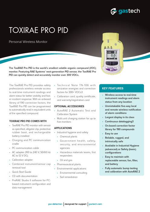
• Wireless access to real-time instrument readings and alarm status from any location • Unmistakable five-way local and remote wireless notification of alarm conditions • Largest display in its class • Continuous datalogging3• On-board correction factor library for 190 compounds • Easy to use• Reliable, rugged, and intrinsically safe• Available in Industrial Hygiene (advanced) or Safety (basic) configurations • Easy to maintain withreplaceable sensor, fan, filter, and battery • Fully automatic bump testing and calibration with AutoRAE 2The ToxiRAE Pro PID provides safety professionals wireless remote access to real-time instrument readings and alarm status for better visibility and fast-er incident response. With an onboard library of 190 correction factors, the ToxiRAE Pro PID can be programmed to automatically read in equivalent units of the specified compound.TOXIRAE PRO PID COMES WITH • T oxiRAE Pro PID monitor with sensoras specified, alligator clip, protective rubber boot, and rechargeable battery installed • Charging and PC communication cradle • PC communication cable• AC adapter (100 to 240 V, 50/60 Hz AC to 12 V DC)• Calibration adapter• Combined instrument/sensor cap removal tool • Quick Start Guide • CD with documentation• ProRAE Studio II software for PC-based instrument configuration and data management• Te c h n i c a l N o t e T N -106 w i t h ionization energies and correction factors for 300+ VOCs3• Calibration card; quality certificate; and warranty/registration card OPTIONAL ACCESSORIES• AutoRAE 2 Automatic Test and Calibration System • Multi-unit charging station for up to five monitors APPLICATIONS• Industrial hygiene and safety • Chemical plants• G overnment health, safety, security, and environmental agencies • Hazardous materials teams, first responders • Oil and gas • Pharmaceutical plants • Environmental applications • Environmental consulting • Soil remediationThe ToxiRAE Pro PID is the world’s smallest volatile organic compound (VOC) monitor. Featuring RAE Systems’ next-generation PID sensor, the ToxiRAE Pro PID can quickly detect and accurately monitor over 300 VOCs.KEY FEATURES。
BW Technologies LP Max XT 气体探测器用户手册说明书

Limited Warranty and Limitation LiabilityBW Technologies LP (BW) warrants the product to be free from defects in material and workmanship under normal use and service for a period of two years, beginning on the date of shipment to the buyer. This warranty extends only to the sale of new and unused products to the original buyer. BW’s warranty obligation is limited, at BW’s option, to refund of the purchase price, repair or replacement of a defective product that is returned to a BW authorized service center within the warranty period. In no event shall BW’s liability hereunder exceed the purchase price actually paid by the buyer for the Product.This warranty does not include:a)fuses, disposable batteries or the routine replacement of parts due to the normal wear and tear of the product arising from use;b)any product which in BW’s opinion, has been misused, altered, neglected or damaged, by accident or abnormal conditions of operation,handling or use;c)any damage or defects attributable to repair of the product by any person other than an authorized dealer, or the installation of unapprovedparts on the product; orThe obligations set forth in this warranty are conditional on:a)proper storage, installation, calibration, use, maintenance and compliance with the product manual instructions and any other applicablerecommendations of BW;b)the buyer promptly notifying BW of any defect and, if required, promptly making the product available for correction. No goods shall bereturned to BW until receipt by the buyer of shipping instructions from BW; andc)the right of BW to require that the buyer provide proof of purchase such as the original invoice, bill of sale or packing slip to establish that theproduct is within the warranty period.THE BUYER AGREES THAT THIS WARRANTY IS THE BUYER ’S SOLE AND EXCLUSIVE REMEDY AND IS IN LIEU OF ALL OTHER WARRANTIES , EXPRESS OR IMPLIED , INCLUDING BUT NOT LIMITED TO ANY IMPLIED WARRANTY OF MERCHANTABILITY OR FITNESS FOR A PARTICULAR PURPOSE . BW SHALL NOT BE LIABLE FOR ANY SPECIAL , INDIRECT , INCIDENTAL , OR BASED ON CONTRACT , TORT OR RELIANCE OR ANY OTHER THEORY .Since some countries or states do not allow limitation of the term of an implied warranty, or exclusion or limitation of incidental or consequential damages, the limitations and exclusions of this warranty may not apply to every buyer. If any provision of this warranty is held invalid or unenforceable by a court of competent jurisdiction, such holding will not affect the validity or enforceability of any other provision.Contacting BW Technologies by HoneywellEmail us at: ********************Visit BW Technologies by Honeywell’s website at: USA: 1-888-749-8878Canada: 1-800-663-4164Europe: +44(0) 1295 700300Other countries: +1-403-248-9226GasAlertMaxXT IIIntroductionThe Quick Reference Guide provides basic information to oper-ate the GasAlertMaxXT II gas detector. For complete operating instructions, refer to the GasAlertMaxXT II Technical Reference Guide provided on the CD-ROM. The GasAlertMaxXT II gas detector (“the detector”) is designed to warn of hazardous gas levels above user-defined alarm setpoints.The detector is a personal safety device. It is your responsibility to respond properly to the alarm.NoteThe detector is shipped with English as the defaultdisplayed language. Additional languages providedare French, German, Spanish, and Portuguese. Thescreens for the additional languages are displayed onthe detector and in the corresponding operator’smanual.Zeroing the SensorsTo zero the sensors, refer to steps #1-3 in Calibration onpage 9.Safety Information - Read FirstUse the detector only as specified in this operator’s manual and the technical reference guide, otherwise the protection provided by the detector may be impaired.Read the following Cautions before using the detector.1GasAlertMaxXT IIGasAlertMaxXT IIGasAlertMaxXT II5GasAlertMaxXT IIParts of the GasAlertMaxXT IIParts of the GasAlertMaxXT II6GasAlertMaxXT IIQuick Reference GuideDisplay ElementsGasAlertMaxXT II78GasAlertMaxXT IIQuick Reference GuideCalibration and Bump Test Installation9CalibrationCalibrationa CautionCalibrate only in a safe area that is free of hazardous gas in an atmosphere of 20.9 % oxygen. Do not calibrate the detector during or immediately after charging is complete.Note The maximum hose length for calibration is 3 ft. (1 m).NoteCalibration can be aborted at any time. To abort calibration, press C . The CAL ABORTED screen displays.1.Press and hold C as the detectorperforms the OFF countdown. Continue to hold C when the detector briefly deactivates.2.The detector activates again andperforms the CAL countdown. Continue to hold C until the countdown is complete to enter calibration.3.flashes while the detectorzeroes all of the sensors.If a sensor fails to auto zero, it cannot be spanned. When auto zero is complete, the LCD displays APPLY GAS.4.Refer to Calibration and Bump Test Installation (page 6). Attach the 0.5 l/min. regulator or the demand flow regulator and apply gas.NoteThe diffusion cover must be attached to the detector to calibrate.K flashes on the LCD. After a sufficient amount of gas has been detected (30 seconds), the detector beeps.flashes while the detectorcompletes the span.5.The LCD displays CAL DUE . Next, a screen displays showing the number of days remaining before calibration is due for each sensor. Last, the LCD displays (e.g.) CAL DUE 180 d . As some sensors require more frequentcalibrations, the LCD displays the earliestcalibration that must be performed.Refer to the following table for information about alarms and corresponding screens.NoteIf the Low Alarm Acknowledge option is enabled in Fleet Manager II, the low alarm can be acknowledged and the audible alarm deactivated by pressing C. If the alarm escalates to a high, STEL, TWA, or multi-gas alarm, the audible alarm reactivates.10LOW BATTERYNote:If enabled, during an alarm condition the Latched Alarms option causes the low and high gas alarms (audible, visual, and vibrator) to persist until the alarm is acknowledged (by pressing C) and the gas concentration is below the alarm setpoint. The LCD continues to display the high peak concentration until the alarm condition no longer exists. Enable/disable Latching Alarms in Fleet Manager II. Local regulations may require the Latching Alarms option be enabled.1112The detector, IR Link adapter, and Fleet Manager II software are required to define options. Refer to the GasAlertMax XT II Technical Reference Guide and Fleet Manager II Operator’s Manual . For user and sensor options, refer to the following:Device Configuration•Startup Message Top Line: Enter a line of text to display on the LCD during startup (maximum 25 characters).•Startup Message Bottom Line: Enter a line of text to dis-play on the LCD during startup (maximum 25 characters).•Lockout on Self-Test Error (sensor alarm lock): If a sensor fails during startup and the Lockout on Self-Test option is enabled, Safety Lock On displays on the LCD and the detector deactivates.•Safe Mode: If enabled, SAFE displays continuously on the LCD unless an alarm condition occurs.•Confidence Beep: If enabled, the confidence beep provides continuous confirmation that the detector is operating correctly. To define how often the detector beeps (every 1-120 seconds), enter the value in the Confidence Interval field. Confidence beep is automatically disabled during a low battery alarm.•Latching Alarms: Enable to ensure an alarm persists until the alarm is acknowledged and the gas concentrations are below the alarm setpoint. The audible alarm can be temporarily deactivated for 30 seconds by pressing C , but the LCD contin-ues to display the high peak concentration until the alarm con-dition no longer exists.•Force Calibration: If enabled, the detector must becalibrated if a sensor is overdue upon startup. User defined (0-365 days) in the Calibration Interval field.•Cal IR Lock (must use IR device to calibrate): If enabled, the detector automatically auto zeros, but the sensors must be•Force Bump: If enabled, a bump test must be performed to ensure the sensor(s) are responding correctly to the test gas. User defined (0-365 days) in the Bump Interval field.•Location Logging: If enabled, a series of numbers (1-999) can be entered on the detector to identify gaswells, plants, and other areas that identify the location where the detector is being used.•Force Block Test: If enabled, a pump block test must be performed during the startup tests.•Datalog Interval (seconds): Define how often the detector records a sample (every 1-120 seconds).•Confidence Interval (seconds): Define how often thedetector beeps (1-120 seconds) when the Confidence Beep option is enabled.•Language: The LCD displays the screens in English , Français (French), Deutsch (German), Español (Spanish), or Português (Portuguese). Select thelanguage from the drop-down menu in Fleet Manager II.Sensor Configuration (H 2S, CO, LEL, and O 2)•Sensor Disabled: Enables/disables the selected sensor.•Calibration Gas (ppm): Define the span gas concentration for each sensor. The span gas concentration must match the span value on the gas cylinder.•Calibration Interval (days): Define the number of days (0-365) when the next calibration is due.•Bump Interval (days): Define the number of days (0-365) when the next bump test is due.•Low Alarm (ppm): Define the low alarm setpoint for each sensor.•High Alarm (ppm): Define the high alarm setpoint for each sensor.Maintenance•TWA Alarm (ppm): Define the time-weighted average (TWA) alarm setpoint (toxic sensors only).•STEL Alarm (ppm): Define the short-term exposure limit (STEL) alarm setpoint (toxic sensors only).•STEL Interval (minutes): Define the short-term exposure limit (STEL) from 5-15 minutes (toxic sensors only).•TWA Period (hours) (TWA moving average (hours): The TWA Period option is used to define a time-weighted mov-ing average of accumulated gases over a period of 4-16 hours, to ensure the worker leaves the area whenthe defined maximum average is accumulated.•Correction Factor (%): Enter the compensation factors for hydrocarbons other than methane. The factor can only beapplied if the LEL sensor has been calibrated with methane (LEL only).•50% LEL = (%CH4): Enter a percentage value to display the LEL reading as %vol., assuming a methane environment (LEL only).•Auto-Zero on Startup: Enable/disable the detector to auto-matically zero the sensor(s) during startup (H2S, CO, LEL, and O2).•LEL by Volume CH4: If enabled, the detector operates assuming a methane (CH4) calibration. Enable to read and dis-play %CH4 values. Disable to read and display %LEL values.•5% LEL Over-span: If enabled, the detector automatically over-spans the LEL sensor by 5% LEL above the span gas concentrations to ensure the detector is in compliance with CAN/CSA C22.2 No. 152.•20.8% Base Reading: When enabled, the detector is configured to detect 20.8% O2 as ambient air. Whendisabled, the detector is configured to detect 20.9% O2as ambient air.•Low Alarm Acknowledge: If enabled, the audible alarm can be temporarily disabled during a low alarmby pressing C. The vibrator, alarm LEDs, and LCDremain operational (toxic and LEL only).MaintenanceTo maintain the detector in good operating condition, perform the following basic maintenance as required.•Calibrate, bump test, and inspect the detector on a regular schedule.•Maintain an operations log of all maintenance, bump tests, cali-brations, and alarm events.•Clean the exterior with a soft damp cloth. Do not use solvents, soaps, or polishes.•Do not immerse the detector in liquids.Charging the Detectora WarningCharge only in a safe area that is free of hazardous gas within temperatures of 32°F-113°F (0°C-45°C).Charge the battery after each workday. To charge the battery, refer to the following procedures and illustration:1.Deactivate the detector.2.Insert the charging adapter plug into an AC outlet.3.Connect the charging adapter to the detector IRreceptacle. Refer to the following illustration.4.Allow the battery to charge for 6 hours.1314a WarningTo avoid personal injury and/or property damage, only use sensors that are specifically designed for the detector.NoteDetectors that are configured for 1, 2, or 3 gases maycontain a dummy sensor in one of the four sensorlocations.To replace a sensor or sensor filter, refer to the following figure,table and procedures #1-13.15161.Deactivate the detector.2.Remove the pump inlet screw and the pump inlet.3.Remove the six machine screws from the rear shell.shell by lifting upward and tilting to the left. Both therear and front shell are laying flat side by side.5.Remove the two PCB screws.6.Lift the PCB upward and tilt to the left. Lay the PCB(sensors facing up) onto the rear shell.17remove.To remove the oxygen sensor, gently insert a screw-driver to the back of the oxygen sensor to push out the sensor.8.Insert the new sensor(s) and replace the sensor filter.9.Reassemble the detector and replace the two PCB screws.10.Replace the six machine screws.11.If required, replace the pump and moisture filter.12.Replace the pump inlet and the pump inlet screw.sensor(s). Refer to Calibration .SpecificationsInstrument dimensions: 13.1 x 7.0 x 5.2 cm (5.1 x 2.8 x 2.0 in.)Weight: 328 g (11.6 oz.)Operating temperature: -20°C 1 to +50°C (-4°F to +122°F)Storage temperature: -40°C 1 to +60°C (-40°F to +140°F)Operating humidity: 10% to 100% relative humidity (non-condensing)Dust and moisture ingress: IP66/IP67Alarm setpoints: May vary by region and are user-defined Detection range:H 2S: 0 - 200 ppm (1 ppm increments)CO: 0 - 1000 ppm (1 ppm increments)O 2: 0 - 30.0% vol. (0.1% vol. increments)Combustible (LEL): 0 - 100% (1% LEL increments) or0-4.4% v./v CH41.Standard release data. This product has extended characteristics. For specifications refer to EAC Ex certificate and Pattern Approval document.1822Combustibles: Plug-in catalytic beadO 2 measuring principle: Capillary controlled concentration sensorAlarm conditions: TWA alarm, STEL alarm, low alarm, high alarm, multi-gas alarm, over limit (OL) alarm, low battery alarm, confidence beep, automatic deactivation alarm, and pump alarmAudible alarm: 95 dB+ at 30 cm variable pulsed beeper with full battery chargeVisual alarm: Red light-emitting diodes (LEDs)Display: Alphanumeric liquid crystal display (LCD)Backlight: Activates upon startup and when the pushbutton is pressed; deactivates after 10 seconds. Also activates during an alarm condition and remains lit until alarm ceases Self-test: Initiated at activation and tests continuously Calibration: Automatic zero and automatic spanUser field options: Startup message, lockout on self-test error, safe mode, confidence beep, latching alarms, force calibration, cal IR lock, force bump, location logging, force block test,set datalog interval, set confidence interval, language selection Sensor options: Sensor enable/disable, set span calibration values, set calibration interval, set bump interval, set alarm setpoints, set STEL interval, set TWA period, auto zero atBattery operating time:One rechargeable lithium polymer: 13 hours (typical)Year of manufacture: The detector's year of manufacture is determined from the serial number. The second and third num-ber after the second letter determines the year of manufacture. E.g., MA 110-000001 = 2010 year of manufacture Approved batteries:North AmericaApproved batteries for GasAlertMax XT II product:Lithium-ion polymer battery as per standards EN50020, UL913, C22.2 No. 157Rechargeable battery (MX-BAT01) T emperature code Lithium polymer -20°C ≤ Ta ≤ +50°C T4Battery charger: charging adapter First-time charge: 6 hours Normal charge: 6 hoursWarranty: 2 years including sensors Approvals:Approved by CSA to both U.S. and Canadian Standards CAN/CSA C22.2 No. 157 and C22.2 152GasAlertMaxXT IIThis equipment has been tested and found to comply with the limits for a Class B digital device, pursuant to Part 15 of the FCC Rules and ICES-003 Canadian EMI requirements. These limits are designed to provide reasonable protection against harmful interference in a residential installation. This equipment generates, uses and can radiate radio frequency energy and, if not installed and used in accordance with the instructions, may cause harmful interference to radio communications. However, there is no guarantee that interference will not occur in a partic-ular installation. If this equipment does cause harmful interfer-ence to radio or television reception, which can be determined by turning the equipment off and on, the user is encouraged to •Reorient or relocate the receiving antenna.•Increase the separation between the equipment and receiver.•Connect the equipment into an outlet on a circuit different from that to which the receiver is connected.•Consult the dealer or an experienced radio/TV technician for help.CSA Class I, Division 1, Group A, B, C, and DATEX CE 0539 g II 1 G Ex da ia IIC T4 GaKEMA 08 ATEX 0001EN 60079-0, EN 60079-1, EN 60079-11IECEx Ex da ia IIC T4 Ga CSA 07.0012IEC 60079-0, IEC 60079-1, IEC 60079-11INMETRO Ex ia IIC T4 Ga DNV 12.0135KTL12-KB4BO-0054aa. /~/media/honey-well-analytics/products/gasalertmax-xt-ii/documents/certi-fications/koreanexcertificate_bw_gamaxxtii_12kb4-bo0054.pdf?la=enIP IP66/IP6719GasAlertMaxXT II20。
万能气体探测器XP-3110 XP-3140 XP-3160 使用说明书

■ XP-3110(可燃性气体探测器)便携式气体探测器■ XP-3140(高浓度气体探测器)使用说明书■ XP-3160(高灵敏度气体探测器) 本使用说明书记载有左面所示3种机型的使用方法。
● 请妥善保管本使用说明书,以便随时取阅。
● 请认真阅读本使用说明书再加以使用。
目 录包装内附属品的说明 (1)1.前言 (2)防爆相关事项 (2)符号图标的说明 (2)安全使用说明 (3)2.各部分名称与功能 (4)3.使用方法 (7)使用程序 (7)气体报警相关事项 (10)各种功能及设定方法 (11)峰值保持的设定 (12)报警蜂鸣器静音设定 (13)对象气体的切换 (14)记录数据 (15)数据读取 (16)时间设定 (17)4.异常报警 (18)5.消耗品的更换方法 (19)过滤片的更换 (19)电池的更换 (19)AC适配器(选购)的使用方法 (20)6.维护保养 (21)日常检查 (21)定期检查 (21)主要更换部件 (21)7.判断故障之前 (22)8.保修规定 (23)9.规格 (24)10.检测原理 (25)11.术语的说明 (26)12.环境保护使用期限 (27)—包装内附属品的说明—包装箱内装有下述物品。
使用前务请检查是否齐全。
虽然每台产品都已经过严格检验,但是万一产品出现了破损或缺失,请致电供应商或本公司。
我们将为您寄送。
名 称 数量便携式气体探测器主体(带便携包) 1背带 11m气体导管(带排污过滤器及吸管) 1更换用过滤片(FE-2)2片装 15号碱性电池 4使用说明书 1操作说明卡 1合格证 1选购品(另售)名 称 数量数据收集装置※各1软件(CD-R)USB线(1.8m)AC适配器 AD-21(有防爆要求的情况下,仅限在非危险场所使用)※ 电脑最低配置要求:·OS:MS-Windows®XP(其它版本下的运行情况未曾确认过)·硬盘空间:剩余空间 6M 以上·CD-ROM驱动器:可读CD-R的CD-ROM驱动器(软件从CD-R安装) ·USB接口:Windows可使用的USB1.1标准以上,可连接A型连接器。
多功能紧急检测气体探测器 使用手册说明书

Oxygen (O2)
0 to 30%
Phosphine (PH3)
0 to 5
Sulfur Dioxide (SO2)
0 to 20
Sensors are not interchangeable
Resolution 1 1 10 0.1 0.01 1 1 1 0.1 0.1% 0.01 0.1
Monitor includes:
red flashing LED, loud 90 dB buzzer, powerful vibration
Durable • Designed to meet IP-65
specifications • Highly resistant to EMI/RFI. Compliant
with EMC Directive 89/336/EEC • Durable, highly impact-resistant,
Applications • Oil and gas • Chemical plants • Fire service • Industrial safety • Pulp and paper • Waste-water treatment plants • Landfill operations • Power plants • Steel mills
Attachments
Stainless steel alligator clip (installed), wrist strap
Warranty
2-year warranty for instruments with O2, CO, and H2S sensors (1 year for all others)
UltraRAE3000便携式气体检测仪操作说明PPT课件

10. 实时协议 该设置可决定数据传输的方式。 P2M(连接线):单点对多点 P2P (连接线):点对点 P2M(无线) :单点对多点
编程模式功能——仪器设置
11. 开启零点校准 此项可设置开机时自动进行零点标定
12. 仪器编号 如果网络中有多台仪器需要跟主机通讯时,可以设置此编号来 进行区分。
2. 特种气体采样 使用分离管对苯或者丁二烯进行采样,采样完成后即可测 量这两种气体,具体过程在后面详细讲解
3. 测量值显示 这一屏显示仪器的TWA值,STEL值和峰值
常规模式功能
4. 日期时间温度 这一屏显示仪器的日期,时间和温度
5. 参考标定 更改参考气体
6. 测量气体 更改测量气体
常规模式功能
采样过程中记录数据。
编程模式功能——仪器设置
1. 操作模式 卫检模式:仪器自动连续监测 搜索模式:仅在激活采样时才会监测,处于此模式,看 到屏幕上显示“准备开始采样”,按Y/+开始; 当采样完毕时,按有功能键,屏幕示“停止 采样”,再按左功能键确认即可停止
编程模式功能——仪器设置
2. 现场编号 设置此编号对仪器使用的每个场合进行唯一化标识
提问与解答环节
Questions And Answers
谢谢聆听
·学习就是为了达到一定目的而努力去干, 是为一个目标去 战胜各种困难的过程,这个过程会充满压力、痛苦和挫折
Learning Is To Achieve A Certain Goal And Work Hard, Is A Process To Overcome Various Difficulties For A Goal
2. 报警模式 自动复位:报警条件不存在时,报警停止并复位 锁 定:报警触发后不会自动停止,只能通过手动停 止
梅思安说明书
Ultima-X系列气体探测器使用说明书(请以原版说明书为准)中美合资无锡梅思安安全设备有限公司WUXI MSA SAFETY EQUIPMENT CO. LTD.重要的警告本说明书只是对该类仪表作简要的介绍,具体使用说明请按原版英文说明书为准。
任何负责或将要负责安装、使用或维修本产品的人员都必须仔细阅读本说明书。
象任何复杂的设备一样,只有按照制造厂家的说明与要求去安装、使用及维修,才能使本仪表按设计的性能要求去年工作,否则,仪表将不能正常工作而致使依靠此仪表来保障安全的愿望无法实现,甚至发生更为严重的伤亡事故。
如果不按照本手册的说明去安装、使用及维修本仪表,无锡梅思安公司对本产品所作的保证将是无效的。
因此,请遵守本手册说明以保障你本人及员工的安全,欢迎用户在使用本产品之前写信或打电话来询问有关使用或维修方面的信息。
1注意事项1、本手册所叙述的变送器应按照产品标签、注意事项、警告等项说明(并仅限在指明的范围内)去安装、操作和维修保养。
2、为防止在危险环境下引燃起爆,当接通电源时探测器的防爆盒盖务必密闭。
如需打开盒盖维修或标定,先要确认环境空气中无可燃性气体存在,直至关上盒盖。
3、探测器设计用来检测空气中的可燃性气体、毒气、氧气或其蒸汽浓度,而不能测定水汽中或惰性气体中或严重缺氧环境中的可燃性气体与蒸汽浓度。
4、探测器探头探测器隔爆片上不能被粘污或涂漆。
如在安放探测器的场所进行喷漆,须注意确保探测器入口处的粉末冶金隔爆片上不能粘有漆,否则,漆会阻碍被监测的气体扩散进入探测器。
安装时探测器朝下并离地面至少0.3M,以方便检修及标定,要杜绝雨水的滴入和地面水的溅入。
5、确保探测器正常工作的唯一方法是用已知浓度的气体对探测器进行标定检查,因此标定检查应作为此系统日常检查工作的一部分。
6、探测器的电源电压为7~30VDC,推荐工作电压为24VDC。
超过30VDC的电压将导致仪表的永久性损坏!7、在进行本手册所介绍的操作和保养时,只可以使用真正无锡梅思安公司的配件,否则,可能会严重影响仪表性能。
Zoomlion XNX Universal Transmitter 气体检测设备说明书
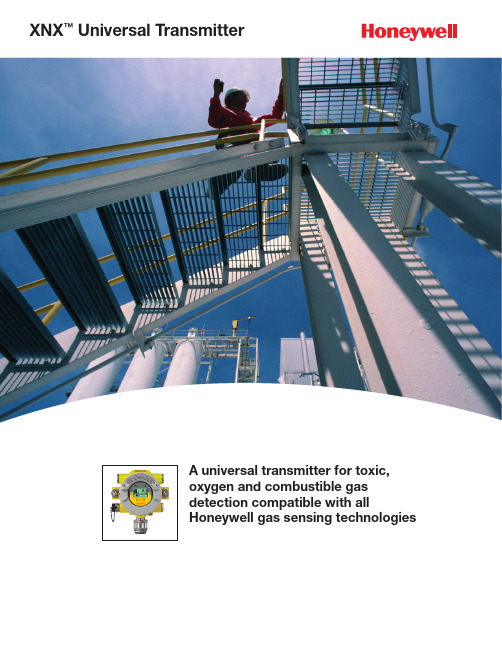
A universal transmitter for toxic, oxygen and combustible gas detection compatible with allHoneywell gas sensing technologiesXNX ™Universal TransmitterThe XNX Universal Transmitter, now with HART EDDL, marks a new turn in gas detection from Honeywell Analytics. It supports the widest range of sensors on a common platform and offers a modular choice of inputs and outputs.Bringing together the best solutions in gas detection High performance• Flammable gas detection 0 to 100% LFL/LEL • P oint IR with heated optics provides immunity to poisoning and no hidden faults • O pen-path IR flammable gas detection in LEL-m measurement• Electrochemical cell offers toxic gas detection in ppm • I R cell provides CO 2 and combustible gas monitoring • R obust and reliable operation in explosive areas and harsh environmentsFlexible Operation• 3 versions - supports (Catalytic Bead and IR Cell), Electrochemical Cell and IR (point and open-path) gas detection • M ulti-Purpose Detector (MPD) with field serviceable mV,Catalytic bead and IR Cell capability• 4-20mA with HART ® as standard• H ART Enhanced Device Description Language(EDDL) software*• M ultiple communications options include up to 3 relays, MODBUS ® and FOUNDATION ® H1 Fieldbus• O ptional local IS port for handheld HART configuratorEasy to Use • L arge, backlit, easy-to-view LCD display offers multi-sensory indicators (visual icons, colored buttons, text, etc.) to display gas and sensor readings • U ser interface supported by 8 selectable languages (English, Spanish, German, Italian, Portuguese, French, Russian, Chinese)• Self-test and fault indication features • N on-intrusive, one-man operation • Q uick calibration with auto-inhibitEasy to Install• 3 or 4 wire operation, source, sink or isolated • Simple plug-in sensors and replaceable cells • N EMA 4X IP66 rated for rugged indoor/outdoor use • F ive conduit entries for ease of installationCost Effective• Minimal training required • One-man operation• Plug-in sensor replacement • A ll necessary accessories includedXNX is designed for flexible integration, simple installation, user-friendly operation and straight-forward maintenance. It is ideal for use with a range of gasmonitoring controllers or industry standard PLCs. The introduction of our HART Enhanced Device Descriptor Language (EDDL) software provides users with an at-a-glance indication of the health of their gas detectors in the field.Electrochemical • P roven electrochemical sensing technology • S urecell™ electrochemical cells are ideal for hot and humid environments • L ong life sensing cells (typical >2 years)• P atented ‘Reflex’ sensing elementverification diagnostics• S ensor recognition software autoconfigures transmitter• P lug and play factoryconfigured sensors• I ntrinsically safe sensor connectionpermits hot swap, reducing down timeCatalytic Bead • S upports Honeywell Analytics 705, 705HT, Sensepoint, Sensepoint HT and MPD sensors • F ast response to wide range of hydrocarbons and flammablesInfrared (Open Path IR, Point IR, IR Cell)• S upports Honeywell Analytics Searchline Excel, Searchpoint Optima Plus • Failsafe operation • Fast speed of response • Reduced routine maintenance • Immune to catalytic poisons • Long operating life • Works in inert atmospheresThe XNX’s powerful advancedcommunications module – including our new HART EDDL software – adds increased efficiency, functionality and flexibility to a gas detection network.XNX offers a variety of communication options to suit your industrial operation’s unique and changing needs. HART communication comes standard on the XNX — with optional EDDL — along with optional Modbus, Foundation Fieldbus or relays. It can interface with a PLC and a host of other protocol compatible devices found in industrial applications. Unique to the XNX and Honeywell Analytics is our new HART EDDL software, which allows you to manage all of your HART devices’ advanced diagnostic data right from your PLC.With the XNX, you are freed from the need to add extra controllers, junction boxes, relays, monitors and other equipment accessories. The integration of our EDDL software also enables the XNX to work with a number of third-party distributed control systems (DCS).Searchline ExcelFoundation Fieldbus705/705HTadvanced diagnostic data at any time.of your HART device.DS01071_v4 8/11© 2011 Honeywell AnalyticsFind out more Contact Honeywell Analytics:AmericasHoneywell Analytics, Inc.405 Barclay Blvd.Lincolnshire, IL 60069USATel: 847.955.8200Toll-free: 800.538.0363Fax: 847.955.8210***********************Technical Services************************Europe, Middle East, Africa Life Safety Distribution AG Weiherallee 11a CH-8610 Uster SwitzerlandTel: +41 (0)44.943.4300Fax: +41 (0)44.943.4398**************************Asia PacificHoneywell Analytics, Asia Pacific #508, Kolon Science Valley (1)187-10 Guro-Dong, Guro-Gu Seoul, 152-050KoreaTel: +82 (0)2.2025.0307Fax: +82 (0)2.2025.0329**************************Please Note:While every effort has been made to ensure accuracy in this publication, no responsibility can be accepted for errors or omissions.Data may change, as well as legislation, and you are strongly advised to obtain copies of the most recently issued regulations, standards, and guidelines. This publication is not intended to form the basis of a contract.Honeywell Analytics Lines of BusinessCommercialGas detection from standalone units to fully engineered, multi-point systems, all offering cost-effective regulatory compliance» Applications: parking structures, chillers, mechanical rooms, office towers, commercial buildings,shopping centers, swimming pools, golf courses, schools and universities, laboratoriesIndustrialRenowned Sieger and Manning gas detection systems with advancedelectrochemical, infrared and open path sensing technologies» Applications: oil and gas, cold storage, water/wastewater treatment,chemicals, engine rooms, plastics and fibers, agriculture, printing and light industrialHigh Tech/GovernmentA complete portfolio of gas and chemical detection instrumentation includinginfrared spectroscopy (MST) with no cross interference, to Chemcassette paper-based solutions (MDA Scientific) offering detection down to parts per billion » Applications: semiconductormanufacturing and nanotechnology, aerospace propulsion and safety, s pecialty chemicals industry, research laboratories, emergency responsePortablesSingle or multi-gas Lumidor and other premium detectors with compact, lightweight designs ranging from simple alarm only units to advanced, fully configurable and serviceable instruments» Applications: underground utility and electricity ducts, boiler rooms, post-fire sites, sewers, industrial plants, industrial hygiene, first responder teams, remote fleetsTechnical Services24/7 global network includes post-sales service and Systems Integration teams» Emergency call out, servicecontracts, on/off-site repair, training and commissioning» Complete range of spares, consumables and accessories。
气体检测仪使用说明书

目录1.产品概述..................................................................................................................... 错误!未定义书签。
2.技术指标.. (2)3.安装说明 (3)3.1 安装结构图 (3)3.2 安装位置 (3)3.3 安装方法 (3)3.3.1墙壁式安装 (4)3.3.2管装式安装 (4)4.标定说明..................................................................................................................... 错误!未定义书签。
5.使用注意事项.. (4)6.常见故障及维修 (5)7.质量保证..................................................................................................................... 错误!未定义书签。
8.责任限定..................................................................................................................... 错误!未定义书签。
备注:............................................................................................................................... 错误!未定义书签。
2. 产品特点● LCD液晶屏幕,可实时显示检测器的浓度、状态;●使用数字信号传输,可靠性高;●可通过计算机实现本地监控及远程监控,检测器运行状态数据可永久储存;●使用485通讯协议,可靠性高;●隔爆式设计适用于危险条件1、2区;●防水、防尘的结构设计;3.技术参数表1 技术指标表4.安装说明4.1安装结构图图1 气体检测仪外形结构4.2 安装位置●气体检测仪与释放源的距离室外不宜大于2 m ,室内不宜大于1 m ;室内7.5米半径内至少安装一个气体检测仪;●气体检测仪安装位置宜在气体释放源的最小频率风向的上风侧;●要根据被测气体与空气的比重来确定安装高度;●要根据泄漏点人员出现的频率和停留时间、生产设备的新旧程度来选择安装数量,以期达到最佳的安装效果;●要防止高温热源的辐射,过高的温度会降低传感器的性能和使用寿命;●气体检测仪与可能的泄漏点要保持适当距离如需更具体说明,请参考:《石油化工企业可燃气体和有毒气体检测报警设计规范SH3063-1999》4.3 安装方法安装形式可以是墙壁固定式或管装式。
X便携式四合一气体检测报警仪说明指导书
X-4便携式四合一气体检测仪(气体检测报警器)使用说明书Operatiom Manual目录1、概述2、结构特征3、技术特征4、功效和操作5、菜单操作6、使用注意事项7、常见故障及其处理方法8、储存9、配件及其它10、附表一、概述本便携式气体检测仪(以下简称检测仪)采取了最优异大规模集成电路技术,国际标准智能化技术水准设计技术及专有数字模拟混合通讯技术而设计完全智能化气体检测仪。
检测仪采取自然扩散方法检测气体,敏感元件采取优质气体传感器,含有极好灵敏度和出色反复性,使用和维护方便,极大满足了工业现场安全监测对设备可靠性要求,外壳采取高强度工程塑料,强度高、手感好、而且防水、防尘、防爆。
本检测仪广泛应用于石油、化工、环境保护、冶金、炼化、燃气输配、生化医药、农业等行业。
1.1本产品设计、制造、检定遵守以下国家标准:GB3836.1-《爆炸性环境第1部分:设备通用要求》GB3836.4-《爆炸性环境第4部分:由本质安全型“i”保护设备》GB15322.3-《便携式可燃气体探测器第3部分:测量范围为(0~100)%LEL便携式可燃气体探测器》JJG693-《可燃气体检测报警器检定均规程》JJG365-电化学氧测定仪检定规程JJG695-硫化氢气体检测仪检定规程JJG915-一氧化碳检测报警器检定规程二、结构特征及工作原理2.1结构功效对照表1、2、3 报警指示灯窗口 7 气体感应孔 4 左键 8 充电口 5 中键 9 液晶屏 6 右键2.2检测仪结构:关键由壳体、线路板、电池、显示器、传感器、充电器等部件组成 2.3工作原理:电化学式和催化燃烧式三、技术特征 常规气体检测范围: 气体种类 量程 低报警点 高报警点 分辨率 EX (0~100)%LEL 20%LEL 50%LEL 1%LEL H2S (0~100)PPM 10PPM 20PPM 1PPM CO (0~1000)PPM 200PPM 500PPM 1PPM O2(0~30)%VOL19.5%VOL23.5%VOL0.1%VOL其它组合气体请联络企业响应时间:T<30s指示方法:LCD显示实时数据及系统状态发光二极管、声音、振动指示报警、故障及欠压工作环境:温度-20℃~50℃;湿度<95% RH(无结露)工作电压:DC3.7V(锂电池容量mAh)防爆标志:Ex ib IIB T3 Gb充电时间:6h~8h待机时间:大于8小时传感器寿命2年尺寸:130*65*45(mm)重量:0.5kg四、功效和操作4.1开机自检及预热过程探测器在关机状态下,按下中键约3秒,伴随两声“滴滴”,探测器显示器背光点亮,此时探测器由关机进入开机状态,同时屏幕显示欢迎界面。
便携式气体探测器使用说明
便携式气体探测器使用说明1.首先,确保便携式气体探测器的传感器已经校准。
校准是确认传感器的准确性和灵敏度的过程。
通常需要将探测器放置在一个已知气体浓度的环境中,然后校准仪器读数与已知浓度进行比对。
2.在使用便携式气体探测器之前,必须先了解被测气体的性质和特点。
了解气体的毒性、爆炸性、燃烧性和其它物理特性是非常重要的,以便在检测到有害气体时能够正确判断风险和采取适当的措施。
3.当开始使用便携式气体探测器时,应按下电源开关并等待几秒钟,直到显示屏上的指示变为稳定。
这表示探测器已经自检完成并准备好进行测量。
4.将便携式气体探测器的传感器放置在被测气体附近,并等待一段时间。
探测器将会实时监测空气中有害气体的浓度,并显示在显示屏上。
5.如果探测器检测到有害气体浓度超过了设定的安全阈值,它将发出警报信号,通常是声音和闪光报警。
一旦听到警报声或看到闪光警报,立即采取相应的措施,如撤离现场或戴上防护设备。
6.在使用便携式气体探测器时,要始终关注显示屏上的读数。
如果探测器显示的数值不断增加或超过了安全标准,应该停止工作并采取适当的措施,如通风或用适当设备过滤空气。
7.定期检查探测器的电池电量,并确保充电或更换电池,以确保探测器始终处于工作状态。
探测器通常具有低电量警报功能,可以自动发出警报信号或通过显示屏提醒用户进行充电或更换电池。
8.定期对便携式气体探测器进行维护和保养。
尽量避免碰撞、摔落或水浸,定期清洁传感器和探测器表面的灰尘和污垢,并确保传感器封盖处于良好的状态。
9.当不使用便携式气体探测器时,建议将其存放在干燥、通风且易于访问的地方。
以防止灰尘或湿气进入探测器,从而影响其性能。
总之,便携式气体探测器是一种重要的安全工具,可以帮助我们检测和防范空气中的有害气体。
但就算是使用这种探测器也不能完全取代其他的防护措施和安全规定。
在使用便携式气体探测器的同时,也应该根据具体的场景和需要采取其他的安全防护措施。
IRmax 红外氢化物气体检测器说明书
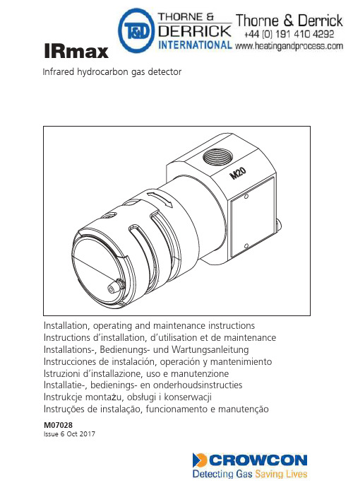
IRmaxInstallation, operating and maintenance instructionsInstructions d’installation, d’utilisation et de maintenanceInstallations-, Bedienungs- und WartungsanleitungInstrucciones de instalación, operación y mantenimiento Istruzioni d’installazione, uso e manutenzioneInstallatie-, bedienings- en onderhoudsinstructiesInstrukcje monta żu, obsługi i konserwacjiInstruções de instalação, funcionamento e manutençãoM07028Issue 6 Oct 2017Infrared hydrocarbon gas detectorContentsConcept and safety (1)IRmax concept (1)Safety information (2)Product overview (3)1.Introduction (4)1.1 General (4)1.2 Product description (4)2.Installation (6)WARNING (6)2.1 Location (6)2.2 Mounting (7)2.3 Cabling directly to IRmax (7)2.3.1 Terminal designation (8)2.3.2 Installing IRmax using a mounting bracket (8)2.4 Installing using a spigot gland and auxiliary junction box (9)2.4.1 To fit IRmax to an auxiliary junction box: (10)2.5 Cabling requirement (10)2.6 Connections and settings (11)3.Operation (12)3.1 Commissioning procedure (12)3.2 Routine maintenance (13)3.3 Changing gas types (13)3.4 Relative responses of gas types (14)4.Specification (15)5. Accessories and spare parts (16)6. Fault finding (17)6.1 Errors signalled by LED (17)6.2 Analogue Output (17)7. RS485 Modbus configuration (18)7.1 General (18)7.2 Wiring topology (19)7.2.1 Star connection (19)7.2.2 Linear bus connection (19)7.3 Cabling requirements (20)7.3.1 Calculating the minimum level of power required (20)7.3.2 Sample calculation (20)8. Functional Safety Manual (21)8.1 Introduction (21)8.2 IRmax and IRmax Modbus Safety Function (21)8.3 Functional Safety Data (21)8.4 Hardware Configuration (22)8.5 Software Configuration (22)8.6 Systematic Failures (22)8.7 Diagnostic Interval (22)8.8 Constraints (22)8.9 Environmental (23)8.10 Hardware fault tolerance (23)8.11 Systematic Capability (23)8.12 Classification (23)Warranty (24)1Detecting Gas Saving LivesConcept and safety2Detecting Gas Saving Lives3 Detecting Gas Saving LivesEx db ia IIC T4 Gb (-40°C ≤ Ta ≤ +75°C)Vmax=32V Wmax=5WIR GAS DETECTOR WITH REMOTE DISPLAY Baseefa09ATEX0220X IECEx BAS 09.0104XAbingdon, United Kingdom, OX14 4SD1180II 2GDEx tb ia IIIC T135°C Db (-40°C ≤ Ta ≤ +40°C) IRmax with IS Barrier certification label4Detecting Gas Saving Lives6Detecting Gas Saving Lives7 Detecting Gas Saving Lives8Detecting Gas Saving Lives9 Detecting Gas Saving Lives10Detecting Gas Saving Lives11Detecting Gas Saving LivesThe 4-20mA signal can be set to current 'Sink' or 'Source' using the pins and jumper link SignalsettingSource settingStatus LED12Detecting Gas Saving Lives13 Detecting Gas Saving Lives14Detecting Gas Saving LivesDiagram 8The diagram shows the approximate response of the gases mentioned above: from left to right, butane, propane, pentane, hexane & petrol vapour and methane.15Detecting Gas Saving Lives16Detecting Gas Saving Lives5. Accessories and spare parts17Detecting Gas Saving Lives18Detecting Gas Saving Lives7. RS485 Modbus configuration7.1 GeneralThis section explains how to use IRmax detectors in a Modbus configuration. An RS485 enabled version is available for such applications. Up to 32 IRmax detectors can be linked in star or bus configurations as described below.Connections to the RS485 version of the IRmax must be made via a spigot gland to an auxiliary junction box (see Section 5 on page 16), rather than by cabling directly into the detector.Please note that the IR Display cannot be used with RS485 enabled IRmax . The RS485 enabled version of the IRmax has five field terminals . The terminals are:1Positive supply 12 V to 30 V above 0 V 20 VReturn and RS485 reference 34-20 mA signal Source or Sink signal (optional)4RS485 B RS485 differential signal 5RS485 ARS485 differential signalThe signals on the RS485 terminals conform to the EIA/TIA-485 standard, which means that the common mode range is -7V to +12V with respect to the 0V terminal.Note that not all RS485 manufacturers agree on the polarity of the A and B signals. If the wiring does not work one way, users should switch the RS485 A&B wires. There is no risk in making the wrong connection.The communication settings are 9600 bps, two stop bits and no parity.When compiling an interface for a control system, it is important to consider the amount of time it takes for the system to collect information from each detector in turn. The fastest speed at which multiple detectors can be polled is 14 detectors per second; practical conditions may reduce this to 7 per second. Users must ensure that the arrangement allows alarm signals to be registered within acceptable time limits.It is also important to ensure that the system can supply enough power to keep all the detectors working. To calculate the amount of power required in a linear bus connection, see Section 7.3, Cabling requirements, on page 20.For full Modbus instructions, contact Crowcon (see addresses on back cover).19 Detecting Gas Saving Lives20Detecting Gas Saving Lives21Detecting Gas Saving Lives8.Functional Safety Manual8.1 IntroductionThe following sections provide detail on the certification of IRmax in accordance with the IEC 61508 and EN 50402 Functional Safety standards. Information is given on the features considered in the safety case, maintenance requirements and data to enable IRmax to be integrated into Safety Instrumented System (SIS).8.2 IRmax and IRmax Modbus Safety FunctionTo measure the concentration of flammable gas and indicate the measurement by means of a 4-20mA output.Failures in respect of the safety function will be detected by the hardware and associated firmware. They will be revealed as an output signal of less than 3.6mA or more than 21mA.8.3 Functional Safety Datafraction, all variants of the system are suitable for use in SIL 2 applications.22Detecting Gas Saving Lives23Detecting Gas Saving Lives24Detecting Gas Saving LivesWarrantyThis equipment leaves our factory fully tested and calibrated. If within the warranty period of three years from despatch, the equipment is proved to be defective by reason of faulty workmanship or material, we undertake at our option either to repair or replace it free of charge, subject to the conditions below.Warranty ProcedureTo facilitate efficient processing of any claim, contact our customer support team on +44 (0)1235 557711 with the following information:Your contact name, phone number, fax number and email address.Description and quantity of goods being returned, including any accessories. Instrument serial number(s).Reason for return.Obtain a Returns form for identification and traceability purposes. This form may be downloaded from our website ‘’, along with a returns label. Alternatively we can ‘email’ you a copy.IRmax will not be accepted for warranty without a Crowcon Returns Number (CRN). It is essential that the address label is securely attached to the outer packaging of the returned goods.The guarantee will be rendered invalid if the instrument is found to have been altered, modified, dismantled, or tampered with. The warranty does not cover misuse or abuse of the unit.Warranty DisclaimerCrowcon accept no liability for consequential or indirect loss or damage howsoever arising (including any loss or damage arising out of the use of the instrument) and all liability in respect of any third party is expressly excluded.This warranty does not cover the accuracy of the calibration of the unit or the cosmetic finish of the product. The unit must be maintained in accordance with the instructions in this manual.The warranty on replacement consumable items (such as the mirror) supplied under warranty to replace faulty items, will be limited to the unexpired warranty of the original supplied item. Crowcon reserves the right to determine a reduced warranty period, or decline a warranty period for any sensor supplied for use in an environment or for an application known to carry risk of degradation or damage to the sensor.Our liability in respect of defective equipment shall be limited to the obligations set out in the guarantee and any extended warranty, condition or statement, express or implied statutory or otherwise as to the merchantable quality of our equipment or its fitness for any particular purpose is excluded except as prohibited by statute. This guarantee shall not affect a customer’s statutory rights.25 Detecting Gas Saving Lives。
便携式气体探测器的操作规程范本

便携式气体探测器的操作规程范本操作规程:1. 安全准备在操作便携式气体探测器之前,必须确保以下安全准备工作已经完成:- 确认已佩戴好适合的个人防护装备,包括防护眼镜、手套和防护服。
- 确保工作区域通风良好,以排除有毒气体的风险。
- 检查便携式气体探测器的电池电量是否充足,如果电量不足,则需要更换电池。
- 阅读并熟悉便携式气体探测器的用户手册,了解相关的操作步骤和注意事项。
2. 打开气体探测器按下便携式气体探测器上的开关按钮,使其处于开启状态。
3. 设置气体类型根据需要检测的气体类型,通过便携式气体探测器上的菜单界面或旋钮,选择对应的气体类型。
4. 校准探测器在使用便携式气体探测器之前,需要进行校准操作以确保测量结果的准确性。
具体的校准步骤可以参照便携式气体探测器的用户手册进行。
5. 进行气体检测将便携式气体探测器靠近待检测区域,让其在空气中取样。
等待一段时间,直到便携式气体探测器显示出测量结果。
注意观察测量结果的数值,判断是否存在超过安全标准的气体浓度。
6. 操作响应当便携式气体探测器检测到有害气体浓度超过安全标准时,它会通过声音报警或闪光灯等方式发出警示信号。
在此情况下,应立即采取相应的应急措施,包括停止使用有害物质、迅速撤离等。
7. 结束操作在使用便携式气体探测器结束后,及时关闭探测器电源开关,并妥善存放。
清理探测器表面和传感器等部件,确保其干燥和无污染。
8. 日常维护定期检查便携式气体探测器的工作状况,包括电池电量、传感器灵敏度等。
如果发现异常情况,应及时更换电池或进行维修。
9. 储存和运输在储存和运输便携式气体探测器时,应注意避免振动、碰撞等对探测器造成损坏。
同时,确保探测器存放在干燥、通风的环境中,远离易燃易爆物品。
10. 紧急处理在出现严重事故或气体泄漏时,应立即采取相应的紧急处理措施,并及时通知相关部门进行处理。
以上是便携式气体探测器的操作规程,通过遵循这些步骤和注意事项,可以有效地进行气体检测和保障工作环境的安全。
气体探测器的操作方法

气体探测器的操作方法
气体探测器一般需要按照以下步骤进行操作:
1. 准备工作:根据气体探测器的类型选择合适的传感器,并确保传感器处于正常工作状态。
2. 安装位置:根据需要测量的气体类型和浓度,确定合适的安装位置。
一般来说,气体浓度较高的地方需要安装在较低的位置,以便及早探测到气体泄漏。
3. 连接电源:将气体探测器与电源连接,确保电源稳定正常。
4. 配置参数:根据实际需求,使用气体探测器的配置软件或调整按钮设置相应的参数,如报警阈值、报警方式等。
5. 启动校准:根据气体探测器的要求,进行校准操作。
通常情况下,需要使用标准气体对传感器进行校准,以确保测量结果准确可靠。
6. 监测气体:启动气体探测器,开始监测环境中的气体浓度。
根据设定的参数,当气体浓度超过设定的报警阈值时,气体探测器会发出警报,以提醒操作人员采取相应的安全措施。
7. 定期维护:定期检查气体探测器的工作状态和传感器的运行情况,根据需要
进行维护和更换。
需要注意的是,不同类型的气体探测器可能会有一些特殊的操作步骤或要求,因此在具体操作前,最好阅读相关的使用说明和操作手册。
ULTRAMAT23中文说明书
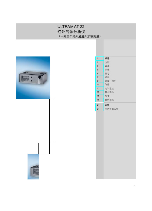
ULTRAMAT 23 红外气体分析仪
(一到三个红外通道外加氧测量)
2
概述
2
应用
3
设计
5
原理
6
型号
7
通讯
9
连接、组件
11 气路
13 电气连接
15 技术指标
16 尺寸
18 订购数据
24 备件 24 附两年的备件
1
ULTRAMAT 23 红外气体分析仪 概述
同时还适用于超过上述量程的所有更大量程。
ULTRAMAT 23 仅用于无潜在爆炸危险的环境中。
应用示例
• 小型燃烧系统的操作优化 • 监测各种燃料(油、气体和煤)燃烧系统排气浓
度以及热焚烧厂的运行检测
• 室内空气监测 • 监测水果贮藏间,温室,地窖及仓库的空气成分 • 监测过程控制 • 钢热处理时环境气体成分监测 • 用于无潜在的爆炸危险的环境中
2
基本特征
ULTRAMAT 23 红外气体分析仪 概述
设计
ULTRAMAT 23也可用于台式安装单元 • 顶盖上两个把手 • 用于放置的 4 个橡胶垫 • 无安装框架
也可用于滑轨
80数字量显示 (4 行/20 字)
防灰尘和可洗 涤膜状键盘
装在分析仪内部 • 凝气阀 • 压力传感器 • 样气泵(选择) • 安全过滤器 流量计带压力开关 用来监测样气流量
OXYMAT 6 针对SW 4.1以前版本: • 德文版 • 英文版 • 法文版 • 西班牙文版 • 意大利文版
订购号 S79610-B4014-A1
C79451-A3494-S501
C79451-A3478-S501 C79451-A3478-S502 C79451-A3478-S503 C79451-A3478-S504 C79451-A3478-S505
采用智能传感技术的下一代气体检测仪表ULTIMA X5000
第27卷 第9期2020年9月仪器仪表用户INSTRUMENTATIONVol.272020 No.90 引言一直以来,工程师们致力于使用多样化的气体检测技术确保油气生产、炼制、储运等环节中的安全等级,最大限度保护人员、设备和设施的安全,如果气体检测系统发生故障,其结果可能是灾难性的。
设计和使用安全、高性能的气体检测系统,能确保较长使用周期内可靠运行,并准确、及时地发现气体泄漏,从而最大限度地避免误报警、误停车等事件的频繁发生。
采用智能传感技术的下一代气体检测仪表ULTIMA X5000施晓东1,马云鹂2(1.中海石油(中国)有限公司 天津分公司,天津 300459;2.梅思安(中国)安全设备有限公司,江苏 苏州 215000)摘 要:简述了常规气体检测技术在石油化工天然气行业实际应用中的潜在问题,并引入智能传感技术的概念。
智能传感技术能够有效减除复杂多变工况环境中不利因素造成的安全风险,有效减少误报警,显著延长仪表标定周期,以及仪表有效寿命。
基于智能传感技术的梅思安下一代气体探测器ULTIMA X5000集成各类先进的检测技术,采用双探头设计,以及更加人性化的触摸屏和OLED 人机界面,适用于SIL2安全完整性等级的功能安全回路应用,显著减少误报警现象,提高安全防护等级。
关键词:智能检测技术;气体检测;误报警;安全失效;自动脉冲检测中图分类号:TH 文献标志码: ANew Generation Gas Detector ULTIMA X5000 Based on InnovativeTruCal Sensing TechnologyShi Xiaodong 1,Ma Yunli 2(1. Tianjin Branch of CNOOC(China) Co., Ltd., Tianjin,300459, China;2. MSA(China) Safety Equipment Co.,Ltd., Jiangsu,Suzhou,215000,China)Abstract:The potential risk of traditional gas detection in oil and gas industry is briefly described, then the innovative technolo-gy of TruCal is introduced. TruCal technology is helpful to effectively mitigate the environment disadvantages, so as to reduce false alarm and extend the calibration interval and lifetime. Based on TruCal technology, MSA next generation intelligent gas detector ULTIMA X5000 integrates diversified sensing technologies, adopting dual-sensor design and humanized HMI design such as touchscreen and OLED indication. X5000 is suitable in function safety applications where SIL2 is required, can help to enhance safety level with better availability.Key words:TruCal;gas detection;false alarm;safe failure;pulse check收稿日期:2020-05-07作者简介:施晓东(1977-),男,江苏海门人,硕士,研究方向:油气行业仪表自动化技术研究和应用。
XGSF-II SF6 气体综合测试仪 使用说明书
XGSF-II SF6气体综合测试仪XGSF-II SF6Gas All-in-One Tester使用说明书User's Manual武汉西高华电电气有限公司Wuhan Xigao Huadian Electric Co.,LTD敬告尊敬的用户:如果您是第一次使用本产品,敬请注意以下事项:◆测量开始,首先全部打开面板上的流量阀,然后用仪器测量管道上的针型阀调节流量。
测量结束,则反之操作。
◆本设备内置大容量锂电池,充满电后可连续工作10小时以上。
◆综合测试仪放置长时间不使用时,在测试管道和气室中会剩有部分空气,因此在第一次测试时,其中的高湿气体会影响其测试速度(针对微水检测),因为被测SF6气体达到饱和前需要先要将空气中的湿气带走。
所以我们会发现当测试第二台SF6电气设备及以后再测量的速度就会很快(3-5分钟)。
◆若单独测试SF6纯度、SF6分解物时,流量应调至0.3L/min。
谢谢合作!目录一、技术特点及参数 (1)二、仪器面板说明 (3)三、测量 (4)四、菜单操作 (5)五、注意事项 (6)六、常见故障及排除方法 (7)七、保修和技术服务 (8)一、技术特点及参数1、技术特点SF6综合测试仪是集SF6(露点)微水仪、SF6纯度仪、SF6分解产物分析仪于一体,将原来要用三台仪器才能实现的功能,集中在一台仪器。
一次现场测量,即可完成三项指标检测,大大节省设备中的气体,一次测量节省2/3气体用量,同时减少用户的工作量,提高了工作效率。
☐快速省气:开机进入测量状态后每SF6气隔露点测定时间为5min左右, SF6纯度、SF6分解物的测量时间为2min左右。
☐自锁接头:采用德国原装进口自锁接头,安全可靠,无漏气。
☐数据存储:采用大容量设计,最多可存储200组测试数据。
☐曲线功能:大屏幕曲线显示露点测量过程。
☐显示清晰:液晶屏直接显示露点、微水(ppm)、SF6纯度、SO2、H2S、CO及HF含量环境温度、环境湿度、时间及日期等内容。
Honeywell BW Ultra五气体探测器说明书

气体探测设备NOSO 2H 2NH 3Cl 2HCNNO 2H 2S O 2CO LEL CO2VOC 功能与优点超简易• 防篡改、一键式操作• 直观 LCD 图标方便快速决策• 维修维护简易超高的可视化程度• 大点阵显示屏方便直观清晰地读取数据• 智能气体布局方便清晰地读取传感器数据• Hole Watch 模式方便快速决策• IntelliFlash™ 及逆向 IntelliFlash™ 方便明确合规性超坚固• 蜂巢式外壳设计更加坚固耐用• 在适当位置进行了防护设计• 防刮擦显示屏保护超连接• 兼容 Honeywell 互联工人• Honeywell TouchConnect™ 技术可实现功能激活• Honeywell SafetySuite 支持仪器配置与报告超舒适• 符合人体工程学设计,易于使用• 质轻但设计坚固• 适合手握,方便取样超快速• 快速反应的传感器技术• 大点阵显示方便快速决策• 通过 IntelliDoX 系统可实现快速冲击和标定Honeywell 一贯坚持将您的安全置于首位。
Honeywell BW™ Ultra 是一 款新型便携式五气体探测器,给予工人安全保障。
Honeywell BW™ Ultra 专为密闭空间应用而设计,可满足密闭空间进入前后的取样和监测,其传 感器技术、可视化气体读数、舒适度与连接性均得到了加强。
该探测器为 用户提供了最可靠且最友好的方式,以避免安全事故。
超强气体探测,性能超凡Honeywell BW™ Ultra 可按照您的需求进行气体探测,并符合所有适用安全法规。
除常规四种气体外,这款探测器的第五种气体传感器可根据用户需求在气体清单中任选,以获得更好的服务,为工人提供额外保护。
Honeywell BW™ Ultra 是市场上首款采用1 系列传感器的气体 探测器,即使是在极端工作条件下,也具有快速响应、性能可靠 以及寿命长等特性。
这意味着高精度和更低成本。
OXYMAT 6 气体分析仪安全手册说明书

Trademarks
All names identified by ® are registered trademarks of the Siemens AG. The remaining trademarks in this publication may be trademarks whose use by third parties for their own purposes could violate the rights of the owner.
Danger
indicates that death or severe personal injury will result if proper precautions are not taken.
Warning indicates that death or severe personal injury may result if proper precautions are not taken.
- 1、下载文档前请自行甄别文档内容的完整性,平台不提供额外的编辑、内容补充、找答案等附加服务。
- 2、"仅部分预览"的文档,不可在线预览部分如存在完整性等问题,可反馈申请退款(可完整预览的文档不适用该条件!)。
- 3、如文档侵犯您的权益,请联系客服反馈,我们会尽快为您处理(人工客服工作时间:9:00-18:30)。
Ultima-X系列气体探测器使用说明书(请以原版说明书为准)中美合资无锡梅思安安全设备有限公司WUXI MSA SAFETY EQUIPMENT CO. LTD.重要的警告本说明书只是对该类仪表作简要的介绍,具体使用说明请按原版英文说明书为准。
任何负责或将要负责安装、使用或维修本产品的人员都必须仔细阅读本说明书。
象任何复杂的设备一样,只有按照制造厂家的说明与要求去安装、使用及维修,才能使本仪表按设计的性能要求去年工作,否则,仪表将不能正常工作而致使依靠此仪表来保障安全的愿望无法实现,甚至发生更为严重的伤亡事故。
如果不按照本手册的说明去安装、使用及维修本仪表,无锡梅思安公司对本产品所作的保证将是无效的。
因此,请遵守本手册说明以保障你本人及员工的安全,欢迎用户在使用本产品之前写信或打电话来询问有关使用或维修方面的信息。
1注意事项1、本手册所叙述的变送器应按照产品标签、注意事项、警告等项说明(并仅限在指明的范围内)去安装、操作和维修保养。
2、为防止在危险环境下引燃起爆,当接通电源时探测器的防爆盒盖务必密闭。
如需打开盒盖维修或标定,先要确认环境空气中无可燃性气体存在,直至关上盒盖。
3、探测器设计用来检测空气中的可燃性气体、毒气、氧气或其蒸汽浓度,而不能测定水汽中或惰性气体中或严重缺氧环境中的可燃性气体与蒸汽浓度。
4、探测器探头探测器隔爆片上不能被粘污或涂漆。
如在安放探测器的场所进行喷漆,须注意确保探测器入口处的粉末冶金隔爆片上不能粘有漆,否则,漆会阻碍被监测的气体扩散进入探测器。
安装时探测器朝下并离地面至少0.3M,以方便检修及标定,要杜绝雨水的滴入和地面水的溅入。
5、确保探测器正常工作的唯一方法是用已知浓度的气体对探测器进行标定检查,因此标定检查应作为此系统日常检查工作的一部分。
6、探测器的电源电压为7~30VDC,推荐工作电压为24VDC。
超过30VDC的电压将导致仪表的永久性损坏!7、在进行本手册所介绍的操作和保养时,只可以使用真正无锡梅思安公司的配件,否则,可能会严重影响仪表性能。
如擅自作超出本手册范围的修理或改动,或由非无锡梅思安指定的维修人员进行修理都可能引起产品不能按照设计性能工作,从而可能会导致依赖于此产品保障安全的用户遭受人身伤害,甚致死亡。
对此本公司将不承担责任。
2目录第一部分:Ultima-X气体探测器1.1:概述1.2:性能指标1.3:安装结构1.4:开机1.5:维修与保养1.6:附件第二部分:Ultima-X标定器、控制器2.1:标定器2.2:控制器2.2.1:概述2.2.2:标定2.2.3:操作2.2.4:维修与保养3第一部分:Ultima-X气体探测器1.1:概述该Ultima-X气体探测器为美国MSA公司进口产品,其结构紧凑,性能优良,可靠性高。
该探测器是监测可燃性气体、有毒有害气体或氧气的全自动化仪表,它的检测原理是:可燃气体为催化燃烧或红外吸收原理;毒气为电化学原理。
该探测器的输出信号有4~20mA标准信号或者内置继电器干触点输出,方便用户使用,并能与MSA的5000、6000、Toxgard,9020/9010系列控制仪表配套使用,亦可连接用户自己的读出装置上使用。
该Ultima-X探测器广泛应用于石油天然气,化工,冶金,油库,矿业,水处理等存在可燃性气体或有毒有害气体的各个行业,是保证工厂安全与人身安全的理想的探测器。
451.3:安装结构Ultima-X 气体探测器有多种型号,外壳全部是符合标准的坚固的不锈钢外壳或坚硬的工程塑料外壳:Ultima-XA是普通外壳,可测毒气、氧气;Ultima-X/XIR是不锈钢外壳,有防爆和非防爆之分,防爆外壳(符合I等1级,B、C、D组危险场所要求),可测可燃气、部分毒气、氧气。
以上多种型号都有双盒式产品(探头远传分离连接)。
如果用户需要订购选择件(如:管道安装组件)与该仪表一起使用,请参看相关的说明。
(具体外形结构见图1, 图2,图3,接线图见图4。
)Ultima-XA外形结构及安装示意图(图1 )Ultima-XA安装示意图6Ultima-X外形结构及安装示意图(图2 )Ultima-XIR安装示意图Ultima-XIR外形结构及安装示意图(图3 )注:ULTIMA-XIR 由于其特殊的光学系统,其安装方式为水平安装。
7Ultima-XA/XE/XIR接线示意图(图4)警告!为了避免人身伤害,在安装连线Ultima-X探测器时,应切断仪表的电源。
在打开Ultima-X防爆型探测器的仪表盖之前,需确认周围环境中无可燃气与空气的混合气体。
否则,如金属物体触及表内电路而产生火花会引起爆炸。
必须严格禁止水和灰尘通过管道和连线进入仪表腔体内。
所以连线接口处的密封圈是必须安装完好的,否则容易损坏仪表线路板,引起仪表故障。
安装本仪表必须遵照国家电气及本地的电气安装规定。
否则可能导致严重的人身伤亡!连线安装步骤:1)打开Ultima-XA仪表的盖子,用“一”字起子, 旋开面板四个角上的固定螺丝,小心向外移出,可以看到图4的接线端子。
打开Ultima-X/XIR 仪表的盖子,只需用手旋开盖子,可以看到有一个拉环,小心地向外拉出,可以看到图4的接线端子。
2)选择某个连接口处将待接电缆线穿进去,在仪表的电路板的接线端子J8上接线。
如使用的是屏蔽电缆,将屏蔽层接在现场导线的屏蔽层上。
83)请认清导线的接线标志,并使接线牢固,以保证接线正确。
4)重新利用拉环按照原来的方位小心地推入线路板,并压紧。
5)将穿线钢管固定在连接口处,将电缆线拉紧以防松弛,注意进线口处密封圈是否紧套在进线电缆上,以防止水或水汽渗入。
6)重新安装固定好仪表的盖子7)连线的距离根据所用的导线线径和探测器是否带继电器输出的不同而有所不同具体如下所示:* 1M(米) =3.28 FEET91.4:开机I、初次开机Ultima-X气体探测器出厂时已由厂家标定好,开机即可使用。
但是为了更好的适合客户的检测气体种类和使用环境,建议第一次通电时进行一次初始标定。
其监测量程及输出是预先设定的。
电源接通后,LCD即显示全部自测项目,以及软件版本号码。
然后,仪表便开始显示气体浓度值,气体种类名称,及其相应的测量单位:.ppm.%气体(仅用于氧气).%LEL正常工作期间,Ultima-X仪表显示其周围环境的气体浓度。
相应的输出信号被输出送到控制器去。
II、标定与任何其他气体探测器一样,探测器需要经常直接通入气体以校正其功能。
标定的间隔时间取决于探测器的工作时间及其所接触的化学物质。
新的探测器需要比较经常地进行标定,直至标定记录显示探测器已稳定,此后,标定即可按常规日程表进行。
Ultima-X可燃气探测器如位于可能有非可燃性化学物质泄漏,如:硅、硅酸盐及卤族元素化合物(含有氟、氯、溴、碘的化学物),可能降低探测器灵敏度。
当需要进行标定调整时,Ultima-X气体探测器可以由单人进行遥控操作。
标定操作需要下列两种附件中的一种:标定器或控制器。
1、标定器具有以下功能:.调零位.标定(零点及量程).改变多路输出型的多路地址编码2、控制器除以上标定器的功能以外,还可进行下列操作:.与MSA Ultima-X带继电器输出一起使用时,设定三级报警点,设定三级报警,故障报警及继电器输出功能。
.显示最近一次完成标定的日期。
.按选定的时间段落显示最高气体浓度读数。
.按选定的时间段落显示平均气体浓度读数。
.改变部分由厂家设定的检测气体量程值及标定值。
.进入有时间和日期标记的时钟功能。
详细标定步骤,请参看说明书第二部分。
1.5:维修与保养1.5.1更换探头在正常的操作条件下,Ultima-X气体探测器基本无需维护。
但是,探头器需要定期更换。
典型情况下,探头使用快到期限必须更换时在Ultima-X气体探测器的LCD显示屏上将出现提示信息CHANGE SENSOR。
警告!探头需小心处置。
电化学探头的密封内芯含有腐蚀性电解液。
如有泄漏,务必小心,切勿接触皮肤、眼睛或衣物,以免烧伤。
如有触及应立即用大量的水冲洗。
如接触眼睛,立即用大量的水冲洗至少15分钟,并请医生诊治。
Ultima-XIR 由于利用的是光学原理,所以对光路系统要求很严格,为了防止水,灰尘,油性物质对镜片的污染,要经常对镜片进行擦拭,只需要用干净,柔和的布,打开防护罩对镜片进行擦拭。
擦拭完毕,进行零位校准和标定即可。
注意:在探测器组件中不可安装有泄漏的探头。
泄漏探头应按照当地或国家有关规定妥善处理。
新的探测器请按MSA部件号定购。
1、Ultima-XE/XA若更换探头,无须切断电源。
2、无需打开探测器主壳体,只需旋开仪表下部的探头。
在取下的时候忌讳迅速取出,最好在取出前滞留10秒钟,然后慢慢取出。
3、请辨认所需探测器的探头型号,并取得相同型号的替换探头。
4、自动对准位置,旋上新的探头,旋紧即可,不可过分用力。
5、接好电源。
即完成了对Ultiam-XE/XA 探头的更换。
注:Ultima-XIR可燃气体探测器的探头需要在切断主电源的情况下,旋开探测器盖子,从主组件线路板上取下探头接线(如图4)。
旋出坏的XIR探头,旋上新的XIR探头,在主组件线路板上接上探头接线(如图4),旋上盖子,即完成了XIR探头的更换。
6、仪表通电稳定,建议按照说明书中第二部分进行初始标定。
这一步骤与标准的标定步骤稍许有些不同。
对新更换探头的探测器使用这一初始标定程序是为了确保Ultima-X仪表的顺利进行气体检测,否则可能导致仪表出现标定故障。
1.6:附件附件A:Ultima-X系列探测器内置继电器输出A.1:概述A.1.1此件设计的目的是当达到报警时,通过内置继电器使得探测器可以去控制其他设备或报警装置。
其中包括三只报警继电器和一只故障继电器。
A.1.2当探测器检测到报警时,即启动适当的报警继电器,同样,如检测到探测器短路或开路、连接电缆短路或开路等故障时,会启动故障继电器。
A.1.3报警继电器出厂时设置为非自锁模式。
对于自锁或非自锁模式,可利用控制器进行设定.注:下列情况下,继电器不响应。
1)上电后一分钟2)标定期间3)标定完成之后二分钟内具体接线图可以参照接线图图4。
第二部分:Ultima-X标定器、控制2.1:标定器2.1.1标定器介绍1 它是一个手握式的由内部两节AAA电池供电的单元;2 无需开盖即可对Ultima-X仪表进行单人标定操作;3 无需任何调整,即可投入使用;4 操作简单,只有三个操作键;5 自动关断标定器本身电源;6 具有UL本安型认证(#117653)2.1.2三个功能键操作1 ZERO 键对Ultima-X探测器执行调零功能;2 CALIBRATE键对Ultima-X探测器执行零点、量程气体的标定功能;在整个标定的过程中需要配备零气和量程气体两种检查气体;3 ADDRESS 键显示或修改多元输出型Ultima-X探测器的地址;所有的对Ultima-X探测器的操作都是通过在7~15cm的距离内将标定器对准探测器的显示窗口,并按键,利用红外连接技术进行通讯从而来完成上述操作。
