omron光电传感器EE-SX671
OMRON光电传感器操作手册
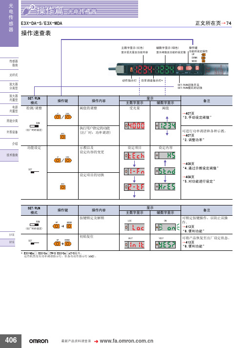
݊Ёӏϔ䬂 ᣝV
᳝Ꮉӊ⢊ᗕϟ
Ꮉ 7(&+ ----
݊Ёӏϔ䬂 ᣝV
Ā----ā䮾⚕
Ā----ā䮾⚕
83 581 '2:1
㟇581
᮴Ꮉӊ⢊ᗕϟ
5)&+ 䯜ؐ
݊Ёӏϔ䬂 ᣝV
7+58
䯜ؐ
ĀᏆ䆒ᅮདⱘ䯜ؐā䮾⚕
ĀᏆ䆒ᅮདⱘ䯜ؐā䮾⚕
ফܝ䞣
䯜ؐ
ফܝ䞣
䯜ؐ
䆒ᅮ㒧ᴳৢˈ䖨ಲࠄ ᪡ࠡⱘᰒ冫
406
᳔ᮄѻક䌘᭭䇋ⱏᔩ
᪡㆛⬉ܝӴᛳ఼
ܝ ⬉ Ӵ ᛳ ఼
⊼
ৠᯊᣝV
䆒ᅮࡼᓣ
ৃҹ䗮䖛ߛᤶᓔ݇䆒ᅮࡼᓣDŽ ࡼᓣ ᪡ /g21 'g21
/
ߎॖᯊⱘ䆒ᅮ
>䖨ಲ߱ྟܝ䞣ᯊ@
'2:1 02'(
ܹܝᯊ21 䙂ܝᯊ21
⊼ᣝ02'(䬂ৢ䇋ゟेᣝ'2:1䬂DŽ
显示 主数字显示
/2&
辅数字显示
21
备注 可锁定按键操作,以防止误操 作。 →413页 “6.便利功能” 可将产品恢复至出厂设定状态。 →413页 “6.便利功能”
UP
MODE
ᡔᴃ㆛ ᪡㆛
6(7
UP DOWN
初始复位
,1,7
<(6"
* E3X-MDA□/E3X-DA□TW-S/E3X-DA□AT-S除外。 这些机型没有功率调谐指示灯,但备有动作指示灯(ch2)。
䗮䖛ᬍ䆒ᅮݙᆍDŽ
ࡳ㛑ৡ鹵
ࡼᓣ Ẕ⌟ࡳ㛑
䆒ᅮݙᆍ ᰒ冫
ܹܝᯊ21˖ǃ䙂ܝᯊ21˖ ᳔ᖿ˖ǃ催䗳˖ǃᷛ˖ޚǃ催㊒ᑺ˖ǃ ᖂߚࡼ˖ ҙ催ࡳ㛑ൟ
EE-_

Ӵᛳ఼
ᦦӊ
ܝ㑸Ӵᛳ఼
⬉ܝӴᛳ఼ ԡ鼠Ӵᛳ఼/ ⌟䭓Ӵᛳ఼ 㾚㾝Ӵᛳ఼/ 䇏ⷕ఼ 䖥Ӵᛳ఼ ᖂൟ ⬉ܝӴᛳ఼ ᮟ䕀㓪ⷕ఼
䍙ໄ⊶Ӵᛳ఼
ⓣ⎆Ẕ⌟఼
品名 型号
接插件 EE-1002
带导线接插件 EE-1003
带导线接插件 EE-1013
带导线接插件 EE-1017
带机器人导线的 接插件
EE-1017-R
使用环境温度范围
材质
罩盖 触头
适用的微型光电传 感器
20mΩ以下 (20mV以下、 100mA以下)
50次以上 极数×6N以下
15MΩ以下 (DC100V以下)
─ 50N以下
10mΩ以下 (DC100V以下)
极数×0.4N以上
─
20N以上
─
1m、 2m
─
1m、 2m
极数×29N以上
─
-10~+60℃
ᛳ
品名
接插件 *1
带导线接插件 *1
带机器人导线接 插件 *1
接插件
接插件 *2 ((+)端子和L
端子短路)
带导线接插件
఼
型号
EE-1009
EE-1010
EE-1010-R
EE-1001
EE-1001-1
EE-1006
形状
项目
接触电阻
插拔寿命 *3
插入力
拔出力 (罩盖保持力)
标准导线长度
锁定强度 *3
带机器人导线的 接插件
EE-1016-R
形状
ѻક䗝ൟ ݅䗮⊼ᛣџ乍 ߍῑൟ ೈ䆒 EE-@
项目
接触电阻
10mΩ以下 (DC10mA及 DC1A)
光电传感器OMRON

光电传感器OMRON什么是光电传感器?光电传感器是一种探测物体存在和运动的设备,可以将光反射、透射、散射等物理现象转换成电信号输出,以实现物体检测和位置控制。
光电传感器的工作原理是利用发射器发射光线,光线照射在被测试物体上,然后由接收器接受反射回来的光线,经过处理电路转换成电信号。
OMRON光电传感器系列OMRON光电传感器系列包含多种不同类型的传感器,包括切割式传感器、感应式传感器、接近式传感器、微型传感器等,可广泛应用于制药、印刷、食品加工、自动化流水线等领域。
切割式传感器切割式光电传感器主要用于反复运动工作的设备上,主要用于通过物体的旋转来检测物体的位置、速度和方向。
OMRON光电传感器系列中的切割式传感器具有高灵敏度、高精度、高速度等特点,可以适应各种要求严格的自动化设备和流水线。
感应式传感器感应式光电传感器主要用于检测非透明材料的存在和位置,比如金属、塑料等材料。
OMRON光电传感器系列中的感应式传感器具有高灵敏度、高信号分辨率、可调目标检测功能等特点,可以实现对各种复杂形状物体的准确探测。
接近式传感器接近式光电传感器主要用于检测透明材料或特定颜色材料的存在和位置,比如透明玻璃、透明薄膜等。
OMRON光电传感器系列中的接近式传感器具有高精度、高重复性、高反应速度等特点,可以实现对透明和半透明物体的高效探测。
微型传感器微型光电传感器主要用于对微小物体的探测和精度测量,比如微型机械零件、电子元件等。
OMRON光电传感器系列中的微型传感器具有小巧的尺寸、高灵敏度、高分辨率等特点,可以实现对微小物体的高精度探测。
OMRON光电传感器的优点OMRON光电传感器具有以下优点:1.高精度:OMRON光电传感器具有高精度的检测和测量功能,可以满足精度要求严格的自动化设备和流水线。
2.高可靠性:OMRON光电传感器采用高品质的材料和先进的制造工艺,能够保证产品的长期稳定性和可靠性。
3.多样化功能:OMRON光电传感器系列包含多种不同类型的传感器,可以满足各种不同类型的检测需求,具有多样化的功能。
omron光电传感器EE-SX671

Photomicrosensor EE-SX67/47 Photomicrosensor with 50- to 100-mASwitching Capacity that can be Builtinto EquipmentPNP output models newly added.Standard, L-shaped, T-shaped, and Close-mount-ing: Five series of models available.Select from thirty output variations, includingLight-ON or Dark-ON/Light-ON (selectable) mod-els.Response frequency as high as 1 kHz.Easy operation monitoring with bright lightindicator.Wide operating voltage range from 5 to 24 VDC.Models (EE-SX jjj A and EE-SX jjj R) withoperation indicators that are lit when sensingobjects are detected (when light is interrupted) areavailable.T-shapedClose-mountingDetection of Lead Frame PositionEE-SX670Lead frameRatingsNote: 1.The indicator is GaP red LED (peak emission wavelength: 690 nm).2.The response frequency was measured by detecting the following rotating disks.Disk2.1 mmCharacteristicsSensing Position Characteristics (Typical)Dark-ON mode Dark-ON moded Tr ONTr OFFd’Tr ONTr OFFDistance d (mm)Distance d (mm)Repeated Sensing Position Characteristics (Typical)No. of repetitions: 20Distance d (mm)OutputleveltransistorV cc = 12 Vn d1 = 0.002 mmn d2 = 0.004 mmn d3 = 0.005 mmn d4 = 0.02 mmn d5 = 0.04 mmOutput Circuit DiagramsEE-SX670/670P EE-SX670A/670REE-SX470/470PT erminal Arrangement 6.9525.4191913.4513.25.56.23.813.82.546.40.820.30.7Two, 3.2-dia. holesFour, R1Optical axis(1)(2)(3)(4)Two, 3.8-dia.holesOperation indicator9Note:Not used in EE-SX470EE-SX671/671PEE-SX671A/671R EE-SX471/471P(1)(2)(3)(4)14.53.26.23.826.219.03.02.5413.05.09.08.39.07.23.613.013.419.06.200.70.62.10.36.956.350.87.2215.5Four, R1.0Operation indicatorOptical axisTwo, 3.2-dia. holes13.4Four, R2TerminalArrangement Note:Not used in EE-SX4713.0EE-SX672/672P EE-SX672A/672R EE-SX472/472P(4)(3)(2)(1)13.73.026.012.6 6.413.45.022.29.06.23.82.5413.06.34.32.50.70.319.00.82136.2Operation indicator (back)Optical axisFour, R1.6Four, R1.0Note:Not used in EE-SX472T erminal ArrangementEE-SX673/673P EE-SX673A/673R EE-SX473/473P12.86.33.5722.292.84.96.23.82.5414.413.450.820.30.7Two, R1Two, 3.2-dia. holes(6.65)(1)(2)(3)(4)Optical axisOperation indicator Terminal Arrangement Note:Not used in EE-SX473EE-SX674/674PEE-SX674A/674R EE-SX474/474PT erminal ArrangementNote:Not used in EE-SX474Optical axisOptical axis markOperation indicatorTwo, 3.5-dia. holesotherwise the EE-SX may be damaged.SensorLoad+–Out Do not make mistakes in wiring, such as mistakes in polarity , other -wise the EE-SX may be damaged.SensorLoad+–Out Do not short-circuit the load (i.e., do not connect a power supply di -rectly to the Sensor) as shown below , otherwise the EE-SX may be damaged.SensorLoadLoadshort-circuiting+–OutMountingThe EE-SX is a Sensor to be built into equipment. Therefore, no special protective measures have been taken to protect the EE-SX from external light disturbance. Make sure that the EE-SX is not affected by incandescent lamps or other light sources that may cause external light disturbance, otherwise the EE-SX may mal-function.Be sure to mount the Sensor securely to flat plates. The characteris -tics of the Through-beam Sensor change if the slot is e M3.0 screws when mounting the EE-SX. Be sure to use spring washers with the screws so that the screws will not loosen. The tightening torque applied to each screw must be no more than 0.59 N S m (6 kgf S cm).Make sure that nothing will come into contact with the sensing ele -ment of the Sensor . If the sensing element has scratch damage, the characteristics of the Sensor will decrease.Make sure that the EE-SX is securely mounted and not loosened by vibration or shock.WiringCountermeasures Against SurgeIf the power supply has surge voltage, connect a Zener diode with -standing 30 to 35 V or 0.1 to 1-µF capacitor in parallel to the power supply to absorb the surge voltage.0.1 to 1 µFthe EE-SX as shown below . Be sure to connect a diode for counter-voltage absorption.RelayOUTDo not wire power lines or high-tension lines alongside the lines of the EE-SX in the same conduit, otherwise the EE-SX may be dam -aged or malfunction due to induction. Be sure to wire the lines of the EE-SX separately from power lines or high-tension lines or lay them in an exclusive, shielded conduit.Voltage OutputA Sensor with open collector output can be connected to a device with voltage-input specifications by connecting a resistor between the power supply and output terminals as shown in the following cir -cuit diagram. The resistance of the resistor is normally 4.7 k Ω and must withstand a power of 0.5 W at 24 V and 0.25 W at 12 V .Sensor main circuitResistorCounter (voltage-input model)+24 V (power supply)Input terminal (CP)Input impedance:approx. 4.7 k ΩOutputEE-SX67/47 NPN modelsEE-SX47/67 NPN Models with a 4.7-k Ω Resistor High level:Input voltage (V H ) =R+Z ZV CC =4.7 k + 4.7 k4.7 k x 24 V = 12 V Low level:Load current (I C ) =RV CC == 5.1 mA x 50 to 100 mA R24 VInput voltage (V L ) x 0.4 V Sensor main circuitResistor+24 V (power supply)Input terminal (CP)Input impedance:approx. 4.7 k ΩOutputEE-SX67/47 PNP modelsEE-SX47/67 PNP Models with a 4.7-k Ω Resistor High level:Input voltage (V H ) = Vcc–residual voltage[24 V–1.3 V=22.7 VLow level:Input voltage (V L ) [0 VNote:Refer to the ratings of the Sensor for the relationship be-tween the residual voltage and load current.OthersDo not wire the EE-SX while power is applied, otherwise the EE-SX may be damaged.Do not install the EE-SX in the following locations, otherwise the EE-SX may be damaged or malfunction.Locations with excessive dustLocations with corrosive gasLocations where water, oil, or chemical is directly sprayed Outdoors or locations exposed to direct sunlightMake sure that the operating ambient temperature is within the rated range.The Sensor may be soluble in organic solvent, acid, and alkaline, aromatic hydrocarbon, and chlorinated aliphatic hydrocarbon sol-vents. The characteristics of the Sensor may decrease as a result. Therefore, make sure that the Sensor is free from these solutions.StandardThrough-beam (slot)5 mm(slot1112Photomicrosensors (EE-SX67/47, 77/87 models) and Connectors(EE-1001/1001-1/1006/1009/1010/1010-R) have been certified as products that conform to the following UL Standard.Certified Date:February 9, 1998Certified Models:All OMRON EE-SX67/47-series Photomicrosensors and the Photomicrosensor Connectors (EE-1001/1001-1/1006/1009/1010/1010-R)File No.:E41515Standard Name:UL508: industrial control devicesCertification Method:UL Recognition (recognition certification for products used in the U.S.A.) and Canadian UL Recognition (recog -nition certification for products used in Canada)Applicable Lot No.:928 and after (products manufactured on and after February 9, 1998)The following Photomicrosensors have been certified as products conforming to the EMC Directives (CE marking).CE Marking Date:April 1, 1998Applicable Models:All EE-SX67/47 (A) models, EE-SX67/47 P , R models All EE-SX77/87 (A) models, EE-SX77/87 P , R models EE-SY671/672EE-SPW311/411EE-SPY311/312EE-SPY301/302EE-SPY401/402EE-SPY411/412EE-SPX302/304/306-W2A EE-SPX402/404/406-W2A EE-SPX303/403EE-SPX301/401ALL DIMENSIONS SHOWN ARE IN MILLIMETERS.To convert millimeters into inches, multiply by 0.03937. T o convert grams into ounces, multiply by 0.03527.Cat. No. E303-E1-1In the interest of product improvement, specifications are subject to change without notice.Printed in Japan 0898-4M (0898) aOMRON CorporationIndustrial Sensors DivisionSensing Devices and Components Division H.Q.28th Fl., Crystal T ower Bldg.,1-2-27, Shiromi, Chuo-ku,Osaka 540-6028 JapanPhone: (81)6-949-6012 Fax: (81)6-949-6021。
OMRON-ee-sx673a

OMRON-ee-sx673a
接近开关是一种无需与运动部件进行机械直接接触而可以操作的位置开关,当物体接近开关的感应面到动作距离时,不需要机械接触及施加任何压力即可使开关动作,从而驱动直流电器或给计算机(plc)装置提供控制指令。
接近开关是种开关型传感器(即无触点开关),它既有行程开关、微动开关的特性,同时具有传感性能,且动作可靠,性能稳定,频率响应快,应用寿命长,抗干扰能力强等、并具有防水、防震、耐腐蚀等特点。
产品有电感式、电容式、霍尔式、交、直流型。
接近开关又称无触点接近开关,是理想的电子开关量传感器。
当金属检测体接近开关的感应区域,开关就能无接触,无压力、无火花、迅速发出电气指令,准确反应出运动机构的位置和行程,即使用于一般的行程控制,其定位精度、操作频率、使用寿命、安装调整的方便性和对恶劣环境的适用能力,是一般机械式行程开关所不能相比的。
它广泛地应用于机床、冶金、化工、轻纺和印刷等行业。
在自动控制系统中可作为限位、计数、定位控制和自动保护环节等。
OMRON-ee-sx673a。
Omron光电开关资料(EE-SX670)

REE-SX470/471/472/473/474/670/671/672/673/674(P)Photomicrosensor with 50mA (PNP)or 100mA (NPN)Switching Capacity that can be Built into EquipmentH Standard,L-shaped,T-shaped,and close mounting models availableH Easy to maintain,plugs into Connector cordset EE-1006H Models available with Light-ON orLight-ON/Dark-ON output configurations H Response frequency as high as 1kHz H Easy operation monitoring with bright LED indicatorHWide operating voltage range (5to24VDC)makes smooth connection of thephotomicrosensor with TTLs,relays,and programmable controllers (PLC)possibleOrdering InformationAppearance Sensing method Slot width Slot depth Output configuration Weight Part number StandardSlot5mm9mmLight-ON Approx.EE-SX470gpp 3.1gEE-SX470PLight-ON/Dark-ON(S t )EE-SX670g /(See note)EE-SX670P L-shaped Light-ON Approx.EE-SX471pgpp 3.0gEE-SX471PLight-ON/Dark-ON(S t )EE-SX671g /(See note)EE-SX671P T-shaped Light-ON Approx.EE-SX472pgpp 2.4gEE-SX472PLight-ON/Dark-ON(S t )EE-SX672g /(See note)EE-SX672P Close-mounting Light-ON Approx.EE-SX473ggpp 2.3gEE-SX473PLight-ON/Dark-ON(S t )EE-SX673g /(See note)EE-SX673P Close-mounting Light-ON Approx.EE-SX474ggpp3.0gEE-SX474PLight-ON/Dark-ON EE-SX674gEE-SX674PNote:The EE-SX67j series models can be used as Light-ON models when the L terminal and positive (+)terminal are short-circuited.To use them as Dark-ON models do not short-circuit these terminals.Connector EE-1001-1can be used for Light-ON operation.EE-SX470/471/472/473/474/670/671/672/673/674(P)EE-SX470/471/472/473/474/670/671/672/673/674(P)2J ACCESSORIESNamePart number Solder connector EE-1001Connector with 2m cable EE-1006Connector holder for EE-1006EE-1006ASpecificationsJ RATINGSItem Standard L-shaped T-shaped Close-mounting Output typeNPN output EE-SX470EE-SX670EE-SX471EE-SX671EE-SX472EE-SX672EE-SX473,EE-SX474EE-SX673,EE-SX674PNP outputEE-SX470P EE-SX670PEE-SX471P EE-SX671PEE-SX472P EE-SX672PEE-SX473P ,EE-SX474P EE-SX673P ,EE-SX474PSupply voltage 5to 24VDC ±10%,ripple (p-p):10%max.Current consumption NPN models:35mA max.,PNP models:30mA max.Standard reference object Opaque:0.8x 2mm Differential distance 0.025mmControl outputNPN open collector output models:At 5to 24VDC:100mA load current (l c )with a residual voltage of 0.8V max.When driving TTL:40mA load current (l c )with a residual voltage of 0.4V max.PNP open collector output models:At 5to 24VDC:50mA load current (l c )with a residual voltage of 1.3V max.Indicator note 1.)Without detectingobject ON (See ote )With detecting objectOFFResponse frequency (See note 2.)1kHz max.(3kHz typ.)Light source GaAs infrared LED with a peak wavelength of 940nm ReceiverSi phototransistor with a sensing wavelength of 850nm max.Connecting methodEE-1001/1006Connectors;soldering terminals/cordsetNote:1.The indicator is GaP red LED (peak emission wavelength:690nm).2.The response frequency was measured by detecting the following disks rotating.Disk2.1mm1mm1mmt =0.2mmEE-SX470/471/472/473/474/670/671/672/673/674(P)EE-SX470/471/472/473/474/670/671/672/673/674(P)3J CHARACTERISTICSAmbient illumination (See note 1.)Fluorescent light:1,000ℓx max.Ambient temperature Operating -25°C to 55°C (-13°F to 131°F)p Storage -30°C to 80°C (-22°F to 176°F)Ambient humidity Operating 5%to 85%y Storage5%to 95%Vibration resistance Destruction:20to 2,000Hz,(with a peak acceleration of 10G),1.5-mm doubleamplitude for 2hrs (with 4-minute cycles)each in X,Y ,and Z directions Shock resistanceDestruction:500m/s 2(approx.50G)for 3times each in X,Y ,and Z directions Soldering heat resistance (See note 2.)260°±5°C when the portion between the tip of the terminals and the position 1.5mm from the terminal base is dipped into the solder for 10±1seconds Degree of protection IEC 60529,IP50MaterialsCase Polybutylene teraphthalate (PBT)CoverPolycarbonate (PC)Emitter/Receiver Polycarbonate (PC)Note:1.The ambient luminance is measured on the surface of the receiver.2.This conforms to MIL-STD-750-2031-1.Engineering DataJ SENSING POSITION CHARACTERISTICS (TYPICAL)Tr ONTr OFFDark-ON modeDistance d (mm)Tr ONTr OFFDark-ON modeDistance d (mm)J REPEATED SENSING POSITION CHARACTERISTICS (TYPICAL)No.of repetitions:20at V cc =12V Distance d (mm)O u t p u t l e v e l t r a n s i s t o rn d1=0.002mm n d2=0.004mm n d3=0.005mm n d4=0.02mm n d5=0.04mmddEE-SX470/471/472/473/474/670/671/672/673/674(P)EE-SX470/471/472/473/474/670/671/672/673/674(P)4OperationEE-SX470/471/472/473/474/670/671/672/673/674(P)EE-SX470/471/472/473/474/670/671/672/673/674(P)5DimensionsUnit:mm (inch)J EE-SX470(P),EE-SX670(P)Two,3.2dia.holesFour,R1Optical axis(1)(2)(3)(4)Two,3.8dia.holesIndicator windowTerminal Arrangement (1)(2)(3)(4)V CCL OUTL (See Note.)OUTPUT GND (0V)25.4(1.00)19(0.75)6.95(0.27)6.4(0.25)13.4(0.53)0.8(0.03)5(0.20)19(0.75)2(0.08)13.8(0.54)0.3(0.01)0.7(0.03)9(0.35)2.54(0.10)13.2(0.52)5.5(0.22)3.8(0.15)6.2(0.24)Note:L Terminal needs noconnection for all EE-SX47j series sensors.J EE-SX471(P),EE-SX671(P)Four,R1.0Indicator windowOptical axisTwo,3.2dia.holesFour,R2(1)(2)(3)(4)Note:L Terminal needs no connection for all EE-SX47j series sensors.Terminal Arrangement(1)(2)(3)(4)V CCL OUTL (See Note.)OUTPUT GND (0V)26.2(1.03)3.0(0.12)3.2(0.13)19.0(0.75)6.2(0.24)9.0(0.35)5.0(0.20)14.5(0.57)7.2(0.28)6.20(0.24)13.4(0.53)3.8(0.15)2.54(0.10)13.0(0.51)9.0(0.35)2.1(0.08) 6.35(0.25)15.5(0.61)2(0.08)0.8(0.03)3.6(0.14)7.2(0.28)13.0(0.51)13.4(0.53)19.0(0.75)0.7(0.03)0.3(0.01)0.6(0.02)6.95(0.27)8.3(0.33)EE-SX470/471/472/473/474/670/671/672/673/674(P)EE-SX470/471/472/473/474/670/671/672/673/674(P)6J EE-SX472(P),EE-SX672(P)Indicator window operation (back)Optical axis4-R1.64-R1.0Terminal Arrangement (1)(2)(3)(4)V CCL OUTL (See Note.)OUTPUT GND (0V)13.7(0.54)2.54(0.10)3.0(0.12)2.9(0.11)3.8(0.15)0.2(0.01)6.2(0.24)5.0(0.20)22.2(0.87)13.4(0.53)9.0(0.35)26.0(1.02)6.4(0.25)12.6(0.50)4.3(0.17)13(0.51)0.8(0.03)19.0(0.75)6.3(0.25)2(0.08)0.7(0.03)6.2(0.24)0.3(0.01)0.1(0.004)0.1(0.004)Note:L Terminal needs no connection for all EE-SX47j series sensors.J EE-SX473(P),EE-SX673(P)Two,R1Two,3.2dia.holes(1)(2)(3)(4)Optical axis Indicator windowTerminal Arrangement (1)(2)(3)(4)V CCL OUTL (See Note.)OUTPUT GND (0V)2.54(0.10)3.8(0.15)6.2(0.24)5(0.20)22.2(0.87)13.4(0.53)9(0.35)0.8(0.03)2(0.08)0.7(0.03)0.3(0.01)6.65(0.26)7(0.28)14.4(0.57)2.8(0.11)4.9(0.19)6.3(0.25)12.8(0.50)3.5(0.14)Note:L Terminal needs no connection for all EE-SX47j series sensors.EE-SX470/471/472/473/474/670/671/672/673/674(P)EE-SX470/471/472/473/474/670/671/672/673/674(P)7J EE-SX474(P),EE-SX674(P)2--R11234Optical Axis Optical Axis MarkTwo 3.5dia holes Light IndicatorNote:L Terminal needs no connection for all EE-SX47j series sensors.Terminal Arrangement (1)(2)(3)(4)V CCL OUTL (See Note.)OUTPUT GND (0V)7(0.28) 2.2(0.09)0.3(0.01)2.1(0.08)0.6(0.02)0.7(0.03)13.6(0.54)9.3(0.37)2.9(0.11)5(0.20)13.0(0.51)2.54(0.10)3(0.12)3.8(0.15)6.2(0.24)21.5(0.85)0.8(0.03)7(0.28)6.2(0.24)2.6(0.10)15.5(0.61)0.1(0.004)JEE-1001SOLDER CONNECTORJ EE-SX67j (P)WITH EE-1001CONNECTOR2.54±0.152.9±113.0(0.51)6.0(0.24)10.8(0.43)22.2(0.87)0.6(0.02)6.0(0.24)10.8(0.43)4.0(0.16)J EE-1006CONNECTOR WITH CABLE(1)(2)(3)(4)Note:Older standard colors are shown inparentheses.Connector comes with a 2-m attached cable.Terminal Arrangement --IEC Colors (1)(2)(3)(4)Brown (Red)Pink (Yellow)Black (White)Blue (Black)LOUTVCC OUTPUT L GND (O V)2.54(0.10)0.6(0.02)11.8(0.46)25(0.98)2,000(78.74)20(0.79)16.2(0.64)5.3(0.21)15(0.59)EE-SX470/471/472/473/474/670/671/672/673/674(P)EE-SX470/471/472/473/474/670/671/672/673/674(P)8J EE-1006A CONNECTOR HOLDERR3Four,R2Four,R1.6(R1)21.9(0.86)25.2(0.99) 1.2(0.05)5.5(0.22)2(0.08)15(0.59)19.4(0.76)10.2(0.40)3(0.12)2.1(0.08)3.6(0.14)3.4(0.13)3.2(0.13)12(0.47)19(0.75)3(0.12)PrecautionsRefer to the the Technical Information Section for general precautions.The sensing window is made of a polycarbonate resin which withstands chloride solvents and strong acids but is soluble in strong alkali,aromatic hydrocarbons,and aliphatic hydrocarbonate chloride solvents.The casing material uses a PBT resin which withstandschemicals and oil but is soluble in strong acid or alkali solvents.The temperature of the terminals at the time of soldering must not exceed the following:Item Temperature Permissible time Remarks Dip260°C10secThe portion be-tween the base of the terminals and 15Iron350°C3secthe position 1.5mm from the ter-minal base must not be soldered.The terminal base uses a polycarbonate resin,which could be deformed by excessive soldering heat.Cat.No.GC APMS-109/02Specifications subject to change without notice.Printed in U.S.A.OMRON ELECTRONICS LLCOne East Commerce Drive Schaumburg,IL 60173NOTE:DIMENSIONS SHOWN ARE IN MILLIMETERS.To convert millimeters to inches divide by 25.4.1-800-55-OMRONOMRON CANADA,INC.885Milner Avenue416-286-6465ROMRON ON--LINEGlobal -- USA --/oei Canada --/ociToronto,Ontario M1B 5V8。
光电传感器
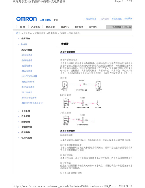
(检测距离 R25mm或
R10mm
素 (中间的 线分散) 耐反 ( 容曲 复代许折 弯弯表性 例 曲 曲良次) 半好数径:10R0万4m次m以上 即难破使损使用机器人手臂等可
三 ④ 角测距
三 三 距离设定型光电传感器主要以 角测距为检测原理。下图所示的是 角测距的原理
元 透 件投射的光线将在检测物体上扩散反射。反射光将通过受光 镜在位置检测
内有检测物体时进行检测。 响。
② 对射按型/检回归测反方射型式的确选认择事项点
检测物体
. 纵×横× 1 大小、形状(
高)
.透明 透明 半透明 透明 2
度(不 体|
体|
.移动 3
速度V(m/s或个/分)
体)
传感器
.1 检测距离(L) .2 形状?大小的限制
a)传感器
板 情况 b)回归反射 (回归反射型的 下)
对射型
超声波传感器
压力传感器 微型光电传感器
回归反射型
接插件中继传感器对应
公司新闻 产品新闻 最新活动 欧姆龙学堂 在线咨询 认证与法规
扩散反射型
光电传感器特长
①检测距离长 如果在对射型中保留10m以上的检测距离等,便能实现其他检测手段(磁性、 ②对检测物体的限制少 由于以检测物体引起的遮光和反射为检测原理,所以不象接近传感器等将检测 等几乎所有物体进行检测。 ③响应时间短 光本身为高速,并且传感器的电路都由电子零件构成,所以不包含机械性工作 ④分辨率高 能通过高级设计技术使投光光束集中在小光点,或通过构成特殊的受光光学系 和高精度的位置检测。 ⑤可实现非接触的检测
欧姆龙学堂-技术指南-传感器-光电传感器
Page 6 of 23
特长
差 可对微小的段 进行检测(BGS、FGS)。 易 影 不 受检测物体的颜色 响(BGS、FGS)。 易 背景 影 不 受 物体的 响(BGS)。 斑 影 有时会受检测物体的 点 响(BGS、FGS)。
Omron 光电传感器选择指南说明书
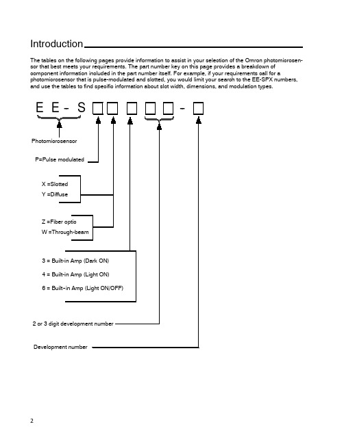
IntroductionThe tables on the following pages provide information to assist in your selection of the Omron photomicrosen-sor that best meets your requirements.The part number key on this page provides a breakdown of component information included in the part number itself.For example,if your requirements call for a photomicrosensor that is pulse-modulated and slotted,you would limit your search to the EE-SPX numbers, and use the tables to find specific information about slot width,dimensions,and modulation types.E E--S--PhotomicrosensorP=Pulse modulatedX=SlottedY=DiffuseZ=Fiber opticW=Through-beam3=Built-in Amp(Dark ON)4=Built-in Amp(Light ON)6=Built--in Amp(Light ON/OFF)2or3digit development numberDevelopment numberAmplified PhotomicrosensorsJ SLOT (TRANSMISSIVE)Slot width Appearance and dimensions (mm)Model Output Optical modulation Aperture width (mm)and orientationPage 3.6mm21.2EE-SPX740Dark-ON Modulated24257.4EE-SPX840Light-ON 2424EE-SPX301Dark-ON 58267EE-SPX401Light-ON 58EE-SPX306-W2ADark-ON 307.42521.2EE-SPX406-W2A Light-ON 3021.2EE-SPX742Dark-ON 24137EE-SPX842Light-ON 0.52421.2EE-SPX302-W2ADark-ON 30137EE-SPX402-W2ALight-ON 3021.2EE-SPX743Dark-ON 24137EE-SPX843Light-ON 2421.27EE-SPX304-W2ADark-ON 3013EE-SPX404-W2A Light-ON 305.0mm15.5EE-SPX741Dark-ON 2427.26.95EE-SPX841Light-ON 2427.215.5EE-SPX305-W2A Dark-ON3015.5EE-SPX405-W2A Light-ON 0.83013.0mmEE-SPX303Dark-ON 54267.4EE-SPX303-15426EE-SPX403Light-ON0.554(This table continues on the next page.)Slot (transmissive)--continued from previous pageSlot width Appearance and dimensions (mm)Model OutputOptical modulation Aperture width (mm)and orientationPage 5.0mm222EE-SX670Light-ON/Dark-ONNon-modulated3822.26.95EE-SX670A 4625.4EE-SX470Light-ON38155EE-SX671Light-ON/Dark-ON 3815.514.5EE-SX671A g 4626.2EE-SX471Light-ON38222EE-SX672Light-ON/Dark-ON3822.226EE-SX672A 4613.4EE-SX472Light-ON38222EE-SX673Light-ON/Dark-ON3822.212.8EE-SX673A 4613.4EE-SX473Light-ON 38155EE-SX674Light-OFF/ON3815.5215EE-SX674A 4621.513.6EE-SX474Light-ON 083818EE-SX770Dark-ON0.8344EE-SX770A31.1EE-SX870Light-ONEE-SX870A EE-SX771Dark-ON 342113EE-SX771AEE-SX871Light-ON18EE-SX871A EE-SX772Dark-ON3431.119.1EE-SX772AEE-SX872Light-ON12EE-SX872AJ DIFFUSESensing distance Sensing method Appearance and dimensions (mm)Model Output Optical modulation Features Page 5.0mmDiffuse reflective20Horizontal modelEE-SPY301Dark-ON ModulatedWide operating voltage range 64267EE-SPY401Light-ON (5to 24VDC)Built-in LED indicatorControl output:6420Vertical modelEE-SPY302Dark-ON p 80mA64267EE-SPY402Light-ON641to 5mm2525.46.95Horizontal modelEE-SY671Light-ON/Dark-ONNon-modulatedBuilt-in sensitivity adjusterWide operating voltage range (5722525.46.95Vertical modelEE-SY672Light-ON/Dark-ONto 24VDC)Output mode selectable72EE-SB5MLight-ON Incorporated 68222EE-SB5MC Dark-ON filter cuts off visible light 6822.2695EE-SB5V Light-ONSensitivity dj t t 686.95EE-SB5VC Dark-ON y adjustment 6819mm (3/4")25.4EE-SB5V-ELight-ON terminals incorporated 682to 6mm (approx.Convergent reflective 22.8Horizontal modelEE-SPY311Dark-ON ModulatedDetects objects against 761/4")268EE-SPY411Light-ON mirror-like surfacesat a distance of more 7622.8Vertical modelEE-SPY312Dark-ON 20mm or more.Detects minute or black objects.76268EE-SPY412Light-ON 76200mmDiffuse retro--EE-SPZ301-ADark-ON Long-distance detection with 80reflective7.42625EE-SPZ401-ALight-ONthe E39-R1Reflector80Note:The maximum detectable distance of each reflective photomicrosensor is based on detecting a piece of white paper with areflection factor of 90%.J FIBER-OPTIC7.42625J THROUGH--BEAMSensing distance Appearance and dimensions (mm)Model Output Optical modulation Detectable object (mm)Page 1m27EE-SPW311Dark-ON ModulatedOpaque:5dia.min.8625.48EE-SPW411Light-ON 8630cm125.8EE-SPW321(-A)Dark-ON Opaque:2dia.min.907.54610.712EE-SPW421(-A)Light-ON90Specialty PhotomicrosensorsSensing Distance Sensing Method Appearance and dimensions (mm)Model Output Optical modulation Features Page 4mmReflective3031.915.4Z4D-F04AAnalogNon-modulatedResolution down to 5μm.1024mmReflective3031.915.4Z4D-F04DON/OFFResolution down to 5μm.1025mmInductive sensing(unshielded)641.328E2R-A01NPN open collectorNoneHigh response frequency of 5khz minimum.98J LIQUID LEVEL SENSORSlot width Appearance and dimensions (mm)Model OutputOptical modulation Aperture width (mm)and orientationPage 13.0mm7.417.22616EE-SPX613Light-ON/Dark-ON Modulated0.896J CONNECTORSModel AppearanceApplicable sensorsEE-1001EE-SX470/470P/670/670P EE-SX471/471P/671/671P EE-SX472/472P/672/672P EE-SX473/473P/673/673P EE-SX474/474P/674/674P EE-1006The connectorincorporates a 2-m wire harness.EE-SX670A/670R EE-SX671A/671R EE-SX672A/672R EE-SX673A/673R EE-SX674A/674REE-SPX303/303-1/403EE-SY671/672EE-SB5M(C)/SB5V(C)EE-SB5V-EEE-SPY311/411/312/412EE-SPW311/411EE-1006A Connector HolderWhen using the EE-1006connectorEE-1006D,1006L The connectorincorporates a 2-m wire harness.EE-SPW311/411EE-1002EE-SPX301/-SPX401,EE-SPY301/-SPY401,EE-SPY302/-SPY402,EE-SPZ301-A/-SPZ401-A,EE-SPZ301Y-01/-SPZ401Y-01,EE-SPZ301W-01/-SPZ401W-01,EE-SPZ301W-02/-SPZ401W-02,EE-1003The connectorincorporates a 1-m wire harness.EE-SPZ301/-SPZ401EE-1003A Connector HolderEE-1010D Z4DEE-1013EE-SPX740/840E22-01E2R-A01J NPN-PNP OUTPUT CONVERTERModel Appearance Applicable sensor Page120 EE-2001EE-SPX301,EE-SPX401,EE-SPY301,EE-SPY401,EE-SPY302,EE-SPY402EE-SPZ301-A,EE-SPZ401-A,EE-SPZ301Y-01,EE-SPZ401Y-01,EE-SPZ301W-01EE-SPZ401W-01EE-SPZ301W-02,EE-SPZ401W-02,EE-SPZ301,EE-SPZ401120 EE-2002EE-SX670,EE-SX670-A,EE-SX671,EE-SX671-A,EE-SX672,EE-SX672-A,EE-SX673,EE-SX673-A,EE-SX470,EE-SX471,EE-SX472,EE-SX473,EE-SPY311,EE-SPY312,EE-SPY411,EE-SPY412,EE-SY671,EE-SY672,EE-SPX303,EE-SPX403,EE-SPW311,EE-SPW411,EE-SB5V,EE-SB5V-E,EE-SB5VC,EE-SB5M,EE-SB5MC。
EE-SY672;EE-SY671;中文规格书,Datasheet资料

Photomicrosensor with sensitivity adjuster.•Easy adjustment with a built-in sensitivity adjuster.•Easy optical axis monitoring with a bright light indicator.•Compact design incorporating a built-in amplifier and special IC enables direct switching capacity of up to 100 mA.•Wide operating voltage range: 5 to 24 VDC•Connection possible with a range of ICs, relays, and Programmable Controllers (PLCs).Be sure to readSafety Precautionsonpage 4.Ordering InformationSensorsterminal.An EE-1001-1 Connector with the terminals already short-circuited is also available.Accessories (Order Separately)*Refer to Accessories for details.Infrared lightTypeCable lengthModel RemarksConnectorEE-1001EE-1001-1L terminal and positive (+) terminal are already short-circuited.EE-1009Connector with Cable1 mEE-1006 EE-1010 2 mEE-1006EE-1010 Connector with Robot Cable1 m EE-1010-R2 mEE-1010-REE-SY671/672Ratings and SpecificationsItemModelsEE-SY671, EE-SY672Sensing distance 1 to 5 mm (Reflection factor: 90%; white paper 15 × 15 mm)*1.The indicator is a GaP red LED(peak wavelength: 690 nm).*2.The response frequency was measured bydetecting the following rotating disk.*3.The ambient illuminance is measured on thesurface of the receiver.Sensing object Transparent or opaque: 15 × 15 mm min.Differential distance 0.5 max. (with a sensing distance of 3 mm, horizontally)Light source GaAs infrared LED with a peak wavelength of 940 nm Indicator *1Light indicator (red)Supply voltage 5 to 24 VDC ±10%, ripple (p-p): 10% max.Current consumption40 mA max.Control outputNPN open collector:Load power supply voltage: 5 to 24 VDC Load current: 100 mA max.OFF current: 0.5 mA max.100 mA load current with a residual voltage of 0.8 V max.40 mA load current with a residual voltage of 0.4 V max.Response frequency *250 Hz min. (Average: 500 Hz)Ambient illumination *31,500 lx max. with fluorescent light on the surface of the receiver Ambient temperaturerangeOperating: −25 to +55°C Storage: −30 to +80°C Ambient humidity range Operating: 5% to 85%Storage: 5% to 95%Vibration resistance Destruction: 20 to 2,000 Hz (peak acceleration: 100 m/s 2)1.5-mm double amplitude for 2 h (4-min periods) each in X, Y, and Z directions Shock resistance Destruction: 500m/s 2 for 3 times each in X, Y, and Z directions Degree of protection IEC IP50Connecting method Special connector (direct soldering possible)WeightApprox. 3.5 g (including screwdriver for adjustment)Material CasePolybutylene phthalate (PBT)Emitter/receiverPolycarbonateAccessoriesScrewdriver for adjustmentDiskEE-SY672EE-SY671DiskEE-SY671/672Engineering Data (Typical)I/O Circuit DiagramsNPN OutputOperating Range Characteristics (Max. Sensitivity)EE-SY67@EE-SY67@Sensing Distance vs. Object Area CharacteristicsSensing Distance vs. Sensitivity VolumeD i s t a n c e Y (m m )Distance X (mm)D i s t a n c e Y (m m )Distance X (mm)Sensing area l 2 (mm 2)S e n s i n g d i s t a n c e (m m )S e n s i n g d i s t a n c e (m m )max.min.Sensing adjuster scaleEE-SY671/672 Safety PrecautionsRefer to Warranty and Limitations of Liability.This product is not designed or rated for ensuringsafety of persons either directly or indirectly.Do not use it for such purposes.Make sure that this product is used within the rated ambient environment conditions.● WiringSoldering•When direct soldering to the terminal, use the following guidelines. Soldering Conditions•The terminal base uses a polycarbonate resin, which could be deformed by excessive soldering heat, resulting in damage to the product’s functionality.Cable Extension•When extending the cable, use an extension cable with conductors having a total cross-section area of 0.3 mm2. The total cable length must be less than 10 m.● InstallationThe photomicrosensor is built into the device being used and so is not equipped to deal with interference from an external light source. When using the sensor in an area exposed to an incandescent lamp, install so as to minimize the effects of external light sources.● Sensitivity AdjustmentUse the special screwdriver (sold together) for sensitivity adjustment.•When an excessive force is applied to sensitivity adjuster, it may be damaged.•The shaft of the sensitivity adjuster is charged. Connect a DC power supply incorporating an insulated transformer to the photomicrosensor. Do not connect a DC power supply incorporating an autotransformer or the user may receive an electric shock when adjusting the sensitivity.WARNING Precautions for Correct UseItem Temperature PermissibletimeRemarksSolderingiron 350°Cmax.3 s max.The portion between the base ofthe terminals and the position1.5 mm from the terminal basemust not be soldered.EE-SY671/672 Sensitivity Adjustment with Background ObjectSensitivity Adjustment with No Background ObjectEE-SY671/672(Unit: mm) Dimensions Tolerance class IT16 applies to dimensions in this datasheet unless otherwise specified. SensorsAccessories (Order Separately)*Refer to Accessories for details.Read and Understand This CatalogPlease read and understand this catalog before purchasing the products. Please consult your OMRON representative if you have any questions orcomments.WARRANTYOMRON's exclusive warranty is that the products are free from defects in materials and workmanship for a period of one year (or other period if specified) from date of sale by OMRON.OMRON MAKES NO WARRANTY OR REPRESENTATION, EXPRESS OR IMPLIED, REGARDING NON-INFRINGEMENT, MERCHANTABILITY, OR FITNESS FOR PARTICULAR PURPOSE OF THE PRODUCTS. ANY BUYER OR USER ACKNOWLEDGES THAT THE BUYER OR USER ALONE HAS DETERMINED THAT THE PRODUCTS WILL SUITABLY MEET THE REQUIREMENTS OF THEIR INTENDED USE. OMRON DISCLAIMS ALL OTHER WARRANTIES, EXPRESS OR IMPLIED.LIMITATIONS OF LIABILITYOMRON SHALL NOT BE RESPONSIBLE FOR SPECIAL, INDIRECT, OR CONSEQUENTIAL DAMAGES, LOSS OF PROFITS OR COMMERCIAL LOSS IN ANY WAY CONNECTED WITH THE PRODUCTS, WHETHER SUCH CLAIM IS BASED ON CONTRACT, WARRANTY, NEGLIGENCE, OR STRICT LIABILITY.In no event shall the responsibility of OMRON for any act exceed the individual price of the product on which liability is asserted.IN NO EVENT SHALL OMRON BE RESPONSIBLE FOR WARRANTY, REPAIR, OR OTHER CLAIMS REGARDING THE PRODUCTS UNLESSOMRON'S ANALYSIS CONFIRMS THAT THE PRODUCTS WERE PROPERLY HANDLED, STORED, INSTALLED, AND MAINTAINED AND NOTSUBJECT TO CONTAMINATION, ABUSE, MISUSE, OR INAPPROPRIATE MODIFICATION OR REPAIR.SUITABILITY FOR USEOMRON shall not be responsible for conformity with any standards, codes, or regulations that apply to the combination of products in the customer's application or use of the products.At the customer's request, OMRON will provide applicable third party certification documents identifying ratings and limitations of use that apply to the products. This information by itself is not sufficient for a complete determination of the suitability of the products in combination with the end product, machine, system, or other application or use.The following are some examples of applications for which particular attention must be given. This is not intended to be an exhaustive list of all possible uses of the products, nor is it intended to imply that the uses listed may be suitable for the products:•Outdoor use, uses involving potential chemical contamination or electrical interference, or conditions or uses not described in this catalog.•Nuclear energy control systems, combustion systems, railroad systems, aviation systems, medical equipment, amusement machines, vehicles, safety equipment, and installations subject to separate industry or government regulations.•Systems, machines, and equipment that could present a risk to life or property.Please know and observe all prohibitions of use applicable to the products.NEVER USE THE PRODUCTS FOR AN APPLICATION INVOLVING SERIOUS RISK TO LIFE OR PROPERTY WITHOUT ENSURING THAT THE SYSTEM AS A WHOLE HAS BEEN DESIGNED TO ADDRESS THE RISKS, AND THAT THE OMRON PRODUCTS ARE PROPERLY RATED AND INSTALLED FOR THE INTENDED USE WITHIN THE OVERALL EQUIPMENT OR SYSTEM.PROGRAMMABLE PRODUCTSOMRON shall not be responsible for the user's programming of a programmable product, or any consequence thereof.CHANGE IN SPECIFICATIONSProduct specifications and accessories may be changed at any time based on improvements and other reasons.It is our practice to change model numbers when published ratings or features are changed, or when significant construction changes are made.However, some specifications of the products may be changed without any notice. When in doubt, special model numbers may be assigned to fix or establish key specifications for your application on your request. Please consult with your OMRON representative at any time to confirm actualspecifications of purchased products.DIMENSIONS AND WEIGHTSDimensions and weights are nominal and are not to be used for manufacturing purposes, even when tolerances are shown.PERFORMANCE DATAPerformance data given in this catalog is provided as a guide for the user in determining suitability and does not constitute a warranty. It may represent the result of OMRON’s test conditions, and the users must correlate it to actual application requirements. Actual performance is subject to the OMRON Warranty and Limitations of Liability.ERRORS AND OMISSIONSThe information in this document has been carefully checked and is believed to be accurate; however, no responsibility is assumed for clerical,typographical, or proofreading errors, or omissions.2008.11In the interest of product improvement, specifications are subject to change without notice. OMRON CorporationIndustrial Automation Company/(c)Copyright OMRON Corporation 2008 All Right Reserved.分销商库存信息:OMRONEE-SY672EE-SY671。
光电开关EE-SX671,EE-SX47X系列.pdf

NPN
EE-SX670 EE-SX670A*2
Model
PNP
EE-SX670P EE-SX670R*3
Weight Approx. 3.1 g
L-shaped T-shaped
Light-ON
Dark-ON/Light-ON (selectable) *1
Light-ON
Dark-ON/Light-ON (selectable) *1
T-shaped
EE-SX672 EE-SX672A EE-SX472
EE-SX672P EE-SX672R EE-SX472P
Close-mounting
EE-SX673 EE-SX673A EE-SX473
EE-SX674 EE-SX674A EE-SX474
EE-SX673P EE-SX673R EE-SX473P
Light-ON
Dark-ON/Light-ON (selectable) *1
EE-SX472
EE-SX673 EE-SX673A*2
EE-SX472P
EE-SX673P EE-SX673R*3
Approx. 2.3 g
Light-ON
EE-SX473
EE-SX473P
Close-mounting
2. The response frequency was measured by detecting the following rotating disks.
Disk
1 mm
2.1 mm
1 mm t = 0.2 mm
2
EE-SX67/47
EE-SX67/47
Characteristics
Item
OMRON-sx674
OMRON-sx674
接近开关是一种无需与运动部件进行机械直接接触而可以操作的位置开关,当物体接近开关的感应面到动作距离时,不需要机械接触及施加任何压力即可使开关动作,从而驱动直流电器或给计算机(plc)装置提供控制指令。
接近开关是种开关型传感器(即无触点开关),它既有行程开关、微动开关的特性,同时具有传感性能,且动作可靠,性能稳定,频率响应快,应用寿命长,抗干扰能力强等、并具有防水、防震、耐腐蚀等特点。
产品有电感式、电容式、霍尔式、交、直流型。
接近开关又称无触点接近开关,是理想的电子开关量传感器。
当金属检测体接近开关的感应区域,开关就能无接触,无压力、无火花、迅速发出电气指令,准确反应出运动机构的位置和行程,即使用于一般的行程控制,其定位精度、操作频率、使用寿命、安装调整的方便性和对恶劣环境的适用能力,是一般机械式行程开关所不能相比的。
它广泛地应用于机床、冶金、化工、轻纺和印刷等行业。
在自动控制系统中可作为限位、计数、定位控制和自动保护环节等。
OMRON-sx674。
omron光电传感器EE-SX671

Photomicrosensor EE-SX67/47 Photomicrosensor with 50- to 100-mASwitching Capacity that can be Builtinto EquipmentPNP output models newly added.Standard, L-shaped, T-shaped, and Close-mount-ing: Five series of models available.Select from thirty output variations, includingLight-ON or Dark-ON/Light-ON (selectable) mod-els.Response frequency as high as 1 kHz.Easy operation monitoring with bright lightindicator.Wide operating voltage range from 5 to 24 VDC.Models (EE-SX jjj A and EE-SX jjj R) withoperation indicators that are lit when sensingobjects are detected (when light is interrupted) areavailable.T-shapedClose-mountingDetection of Lead Frame PositionEE-SX670Lead frameRatingsNote: 1.The indicator is GaP red LED (peak emission wavelength: 690 nm).2.The response frequency was measured by detecting the following rotating disks.Disk2.1 mmCharacteristicsSensing Position Characteristics (Typical)Dark-ON mode Dark-ON moded Tr ONTr OFFd’Tr ONTr OFFDistance d (mm)Distance d (mm)Repeated Sensing Position Characteristics (Typical)No. of repetitions: 20Distance d (mm)OutputleveltransistorV cc = 12 Vn d1 = 0.002 mmn d2 = 0.004 mmn d3 = 0.005 mmn d4 = 0.02 mmn d5 = 0.04 mmOutput Circuit DiagramsEE-SX670/670P EE-SX670A/670REE-SX470/470PT erminal Arrangement 6.9525.4191913.4513.25.56.23.813.82.546.40.820.30.7Two, 3.2-dia. holesFour, R1Optical axis(1)(2)(3)(4)Two, 3.8-dia.holesOperation indicator9Note:Not used in EE-SX470EE-SX671/671PEE-SX671A/671R EE-SX471/471P(1)(2)(3)(4)14.53.26.23.826.219.03.02.5413.05.09.08.39.07.23.613.013.419.06.200.70.62.10.36.956.350.87.2215.5Four, R1.0Operation indicatorOptical axisTwo, 3.2-dia. holes13.4Four, R2TerminalArrangement Note:Not used in EE-SX4713.0EE-SX672/672P EE-SX672A/672R EE-SX472/472P(4)(3)(2)(1)13.73.026.012.6 6.413.45.022.29.06.23.82.5413.06.34.32.50.70.319.00.82136.2Operation indicator (back)Optical axisFour, R1.6Four, R1.0Note:Not used in EE-SX472T erminal ArrangementEE-SX673/673P EE-SX673A/673R EE-SX473/473P12.86.33.5722.292.84.96.23.82.5414.413.450.820.30.7Two, R1Two, 3.2-dia. holes(6.65)(1)(2)(3)(4)Optical axisOperation indicator Terminal Arrangement Note:Not used in EE-SX473EE-SX674/674PEE-SX674A/674R EE-SX474/474PT erminal ArrangementNote:Not used in EE-SX474Optical axisOptical axis markOperation indicatorTwo, 3.5-dia. holesotherwise the EE-SX may be damaged.SensorLoad+–Out Do not make mistakes in wiring, such as mistakes in polarity , other -wise the EE-SX may be damaged.SensorLoad+–Out Do not short-circuit the load (i.e., do not connect a power supply di -rectly to the Sensor) as shown below , otherwise the EE-SX may be damaged.SensorLoadLoadshort-circuiting+–OutMountingThe EE-SX is a Sensor to be built into equipment. Therefore, no special protective measures have been taken to protect the EE-SX from external light disturbance. Make sure that the EE-SX is not affected by incandescent lamps or other light sources that may cause external light disturbance, otherwise the EE-SX may mal-function.Be sure to mount the Sensor securely to flat plates. The characteris -tics of the Through-beam Sensor change if the slot is e M3.0 screws when mounting the EE-SX. Be sure to use spring washers with the screws so that the screws will not loosen. The tightening torque applied to each screw must be no more than 0.59 N S m (6 kgf S cm).Make sure that nothing will come into contact with the sensing ele -ment of the Sensor . If the sensing element has scratch damage, the characteristics of the Sensor will decrease.Make sure that the EE-SX is securely mounted and not loosened by vibration or shock.WiringCountermeasures Against SurgeIf the power supply has surge voltage, connect a Zener diode with -standing 30 to 35 V or 0.1 to 1-µF capacitor in parallel to the power supply to absorb the surge voltage.0.1 to 1 µFthe EE-SX as shown below . Be sure to connect a diode for counter-voltage absorption.RelayOUTDo not wire power lines or high-tension lines alongside the lines of the EE-SX in the same conduit, otherwise the EE-SX may be dam -aged or malfunction due to induction. Be sure to wire the lines of the EE-SX separately from power lines or high-tension lines or lay them in an exclusive, shielded conduit.Voltage OutputA Sensor with open collector output can be connected to a device with voltage-input specifications by connecting a resistor between the power supply and output terminals as shown in the following cir -cuit diagram. The resistance of the resistor is normally 4.7 k Ω and must withstand a power of 0.5 W at 24 V and 0.25 W at 12 V .Sensor main circuitResistorCounter (voltage-input model)+24 V (power supply)Input terminal (CP)Input impedance:approx. 4.7 k ΩOutputEE-SX67/47 NPN modelsEE-SX47/67 NPN Models with a 4.7-k Ω Resistor High level:Input voltage (V H ) =R+Z ZV CC =4.7 k + 4.7 k4.7 k x 24 V = 12 V Low level:Load current (I C ) =RV CC == 5.1 mA x 50 to 100 mA R24 VInput voltage (V L ) x 0.4 V Sensor main circuitResistor+24 V (power supply)Input terminal (CP)Input impedance:approx. 4.7 k ΩOutputEE-SX67/47 PNP modelsEE-SX47/67 PNP Models with a 4.7-k Ω Resistor High level:Input voltage (V H ) = Vcc–residual voltage[24 V–1.3 V=22.7 VLow level:Input voltage (V L ) [0 VNote:Refer to the ratings of the Sensor for the relationship be-tween the residual voltage and load current.OthersDo not wire the EE-SX while power is applied, otherwise the EE-SX may be damaged.Do not install the EE-SX in the following locations, otherwise the EE-SX may be damaged or malfunction.Locations with excessive dustLocations with corrosive gasLocations where water, oil, or chemical is directly sprayed Outdoors or locations exposed to direct sunlightMake sure that the operating ambient temperature is within the rated range.The Sensor may be soluble in organic solvent, acid, and alkaline, aromatic hydrocarbon, and chlorinated aliphatic hydrocarbon sol-vents. The characteristics of the Sensor may decrease as a result. Therefore, make sure that the Sensor is free from these solutions.StandardThrough-beam (slot)5 mm(slot1112Photomicrosensors (EE-SX67/47, 77/87 models) and Connectors(EE-1001/1001-1/1006/1009/1010/1010-R) have been certified as products that conform to the following UL Standard.Certified Date:February 9, 1998Certified Models:All OMRON EE-SX67/47-series Photomicrosensors and the Photomicrosensor Connectors (EE-1001/1001-1/1006/1009/1010/1010-R)File No.:E41515Standard Name:UL508: industrial control devicesCertification Method:UL Recognition (recognition certification for products used in the U.S.A.) and Canadian UL Recognition (recog -nition certification for products used in Canada)Applicable Lot No.:928 and after (products manufactured on and after February 9, 1998)The following Photomicrosensors have been certified as products conforming to the EMC Directives (CE marking).CE Marking Date:April 1, 1998Applicable Models:All EE-SX67/47 (A) models, EE-SX67/47 P , R models All EE-SX77/87 (A) models, EE-SX77/87 P , R models EE-SY671/672EE-SPW311/411EE-SPY311/312EE-SPY301/302EE-SPY401/402EE-SPY411/412EE-SPX302/304/306-W2A EE-SPX402/404/406-W2A EE-SPX303/403EE-SPX301/401ALL DIMENSIONS SHOWN ARE IN MILLIMETERS.To convert millimeters into inches, multiply by 0.03937. T o convert grams into ounces, multiply by 0.03527.Cat. No. E303-E1-1In the interest of product improvement, specifications are subject to change without notice.Printed in Japan 0898-4M (0898) aOMRON CorporationIndustrial Sensors DivisionSensing Devices and Components Division H.Q.28th Fl., Crystal T ower Bldg.,1-2-27, Shiromi, Chuo-ku,Osaka 540-6028 JapanPhone: (81)6-949-6012 Fax: (81)6-949-6021。
欧姆龙光电开关ee-sx671

欧姆龙光电开关ee-sx671
接近开关是一种无需与运动部件进行机械直接接触而可以操作的位置开关,当物体接近开关的感应面到动作距离时,不需要机械接触及施加任何压力即可使开关动作,从而驱动直流电器或给计算机(plc)装置提供控制指令。
接近开关是种开关型传感器(即无触点开关),它既有行程开关、微动开关的特性,同时具有传感性能,且动作可靠,性能稳定,频率响应快,应用寿命长,抗干扰能力强等、并具有防水、防震、耐腐蚀等特点。
产品有电感式、电容式、霍尔式、交、直流型。
接近开关又称无触点接近开关,是理想的电子开关量传感器。
当金属检测体接近开关的感应区域,开关就能无接触,无压力、无火花、迅速发出电气指令,准确反应出运动机构的位置和行程,即使用于一般的行程控制,其定位精度、操作频率、使用寿命、安装调整的方便性和对恶劣环境的适用能力,是一般机械式行程开关所不能相比的。
它广泛地应用于机床、冶金、化工、轻纺和印刷等行业。
在自动控制系统中可作为限位、计数、定位控制和自动保护环节等。
欧姆龙光电开关ee-sx671。
EE-SX671;EE-SX674;EE-SX670A;EE-SX670P;EE-SX671A;中文规格书,Datasheet资料

Infrared light
EE-SX670-C1J-R Models with connectors (0.1m) 0.1M L-shaped Pre-wired Models (1m) EE-SX671-WR 1M
EE-SX671-C1J-R Models with connectors (0.1m) 0.1M T-shaped, slot center 7 mm Closemounting Throughbeam type (with slot) Dark-ON/ Incident Light-ON (slot width) (selectable) * light Pre-wired Models (1m) EE-SX672-WR 1M
T-shaped, slot center 7 mm
Dark-ON/Light-ON Incident light (selectable) *3 No incident light Light-ON Incident light
Closemounting Throughbeam type (with slot) Connector (4 poles)
Dark-ON/Light-ON Incident light (selectable) *3 No incident light
5 mm
(slot width)
Light-ON
Incident light
Closemounting
Dark-ON/Light-ON Incident light (selectable) *3 No incident light Light-ON Incident light
ቤተ መጻሕፍቲ ባይዱ
/
欧姆龙产品及型号
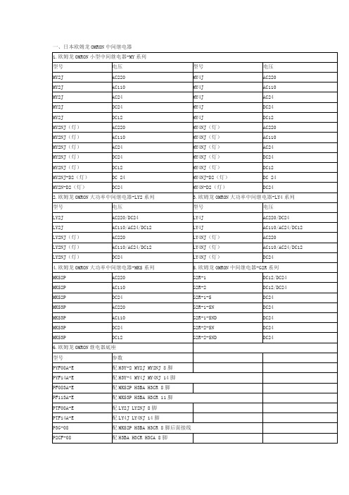
3.欧姆龙OMRON数显定时器-H5CX系列
型号
电压
H5CX-A
AC100-240
H5CX-AD
DC12-48
H5CX-ASD
DC12-48
H5CX-A11
AC100-240
H5CX-L8
AC100-240
H5CX-L8S
AC100-240
H5CX-L8D
DC12-48
E2E-X2ME1-Z
M8 NPN常开
E2E-CR8B1
M4 PNP常开
E2E-X5ME1-Z
M12 NPN常开
E2E-X1R5F1
M8 PNP常开
E2E-X10ME1-Z
M18 NPN常开
E2E-X2MF1
M8 PNP常开
E2E-X18ME1-Z
M30 NPN常开
E2E-X5MF1
M12 PNP常开
M12常开
E2E-X5Y1
M18 NPN常开
E2E-X10MY1
M18常开
E2E-X10Y1
M30 NPN常开
E2E-X18MY1
M30常开
4.欧姆龙OMRON方型通用接近开关TL系列导线引出型
型号
参数
型号
参数
TL-Q5MC1-Z
NPN常开
TL-N10ME1
NPN常开
TL-Q5MC2-Z
NPN常闭
TL-N20ME1
D4N-2122
D4NA-4122
4.欧姆龙OMRON小型限位开关
型号
参数
型号
参数
D4V-8104Z
D4V-8107Z
D4V-8108Z
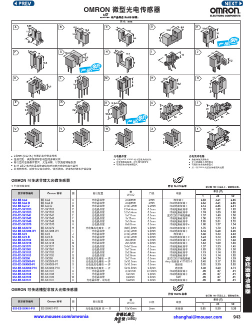
OMRON 微型光电传感器 说明书
943
OMRON 微型光电传感器
/omronia
OMRON 可传送非放大光微传感器包括接线抑制
OMRON 可传送槽型非放大光微传感器
•0.5mm (0.02 in.) 光圈的高分辨率传感•包括过孔、表面贴装和引线型的多种封装
•输出型号包括晶体管只,光达林顿,以及施密特触发器•红外LE D 和光电晶体管确保长时间使用寿命和高可靠性
•非接触传感,适合办公室自动化、钱币处理、游戏和计算机外设设备
光电晶体管:•小到4mm x 5mm 的小型化传送封装•可提供表面贴装、过孔和引线型号•
可提供集成连接器型式
光电集成电路:
•施密特触发器输出•光开启或暗开启的输出•可提供集成连接器型式
•
从1 到5mm 的反射传感距离范围
shanghai@。
欧姆龙各种电气元器件

型号
电压
LY4J
AC220/DC24
LY4J
AC110/AC24/DC12
LY4NJ(灯)
AC220
LY4NJ(灯)
AC110/AC24/DC12
LY4NJ(灯)
DC24
5.欧姆龙OMRON中间继电器-G2R系列
MKS2P
AC220
G2R-1
MKS2P
AC110
G2R-2
MKS2P
DC24
G2R-1-S
欧姆龙光电开关|欧姆龙接近开关|欧姆龙微动开关||欧姆龙液位控制开关|欧姆龙限位开关|欧姆龙继电器|欧姆龙温控器|欧姆龙定时器|欧 欧姆龙旋转编码器|欧姆龙变频器|欧姆龙触摸屏|欧姆龙PLC可编程控制器|欧姆龙传感器|欧姆龙开关电源
OMRON光电开关|OMRON接近开关|OMRON微动开关||OMRON液位控制开关|OMRON限位开关|OMRON继电器|OMRON温控器|OMRON定时器|OMRON计数 编码器|OMRON变频器|OMRON触摸屏|OMRONPLC可编程控制器|欧OMRON传感器|OMRON开关电源
E2E-X2ME1-Z
M8 NPN 常开
E2E-CR8B1
E2E-X5ME1-Z
M12 NPN 常开
E2E-X1R5F1
E2E-X10ME1-Z
M18 NPN 常开
E2E-X2MF1
E2E-X18ME1-Z
M30 NPN 常开
E2E-X5MF1
E2E2-X10MC1
M18 NPN 常开
E2E-X10MF1
滚珠短摆杆型
D4MC-2000
滚珠摆杆型
D4MC-5000
面板安装柱塞型
D4MC-5020
OMRON光电开关671
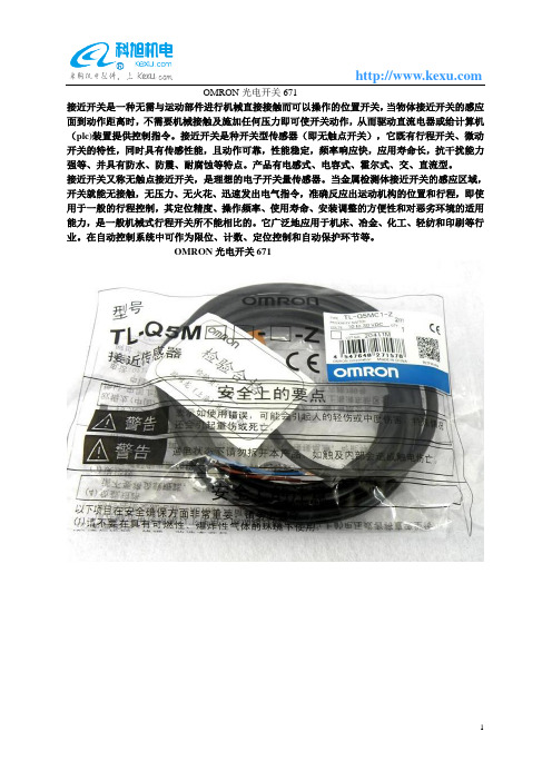
OMRON光电开关671
接近开关是一种无需与运动部件进行机械直接接触而可以操作的位置开关,当物体接近开关的感应面到动作距离时,不需要机械接触及施加任何压力即可使开关动作,从而驱动直流电器或给计算机(plc)装置提供控制指令。
接近开关是种开关型传感器(即无触点开关),它既有行程开关、微动开关的特性,同时具有传感性能,且动作可靠,性能稳定,频率响应快,应用寿命长,抗干扰能力强等、并具有防水、防震、耐腐蚀等特点。
产品有电感式、电容式、霍尔式、交、直流型。
接近开关又称无触点接近开关,是理想的电子开关量传感器。
当金属检测体接近开关的感应区域,开关就能无接触,无压力、无火花、迅速发出电气指令,准确反应出运动机构的位置和行程,即使用于一般的行程控制,其定位精度、操作频率、使用寿命、安装调整的方便性和对恶劣环境的适用能力,是一般机械式行程开关所不能相比的。
它广泛地应用于机床、冶金、化工、轻纺和印刷等行业。
在自动控制系统中可作为限位、计数、定位控制和自动保护环节等。
OMRON光电开关671。
- 1、下载文档前请自行甄别文档内容的完整性,平台不提供额外的编辑、内容补充、找答案等附加服务。
- 2、"仅部分预览"的文档,不可在线预览部分如存在完整性等问题,可反馈申请退款(可完整预览的文档不适用该条件!)。
- 3、如文档侵犯您的权益,请联系客服反馈,我们会尽快为您处理(人工客服工作时间:9:00-18:30)。
Photomicrosensor EE-SX67/47 Photomicrosensor with 50- to 100-mASwitching Capacity that can be Builtinto EquipmentPNP output models newly added.Standard, L-shaped, T-shaped, and Close-mount-ing: Five series of models available.Select from thirty output variations, includingLight-ON or Dark-ON/Light-ON (selectable) mod-els.Response frequency as high as 1 kHz.Easy operation monitoring with bright lightindicator.Wide operating voltage range from 5 to 24 VDC.Models (EE-SX jjj A and EE-SX jjj R) withoperation indicators that are lit when sensingobjects are detected (when light is interrupted) areavailable.T-shapedClose-mountingDetection of Lead Frame PositionEE-SX670Lead frameRatingsNote: 1.The indicator is GaP red LED (peak emission wavelength: 690 nm).2.The response frequency was measured by detecting the following rotating disks.Disk2.1 mmCharacteristicsSensing Position Characteristics (Typical)Dark-ON mode Dark-ON moded Tr ONTr OFFd’Tr ONTr OFFDistance d (mm)Distance d (mm)Repeated Sensing Position Characteristics (Typical)No. of repetitions: 20Distance d (mm)OutputleveltransistorV cc = 12 Vn d1 = 0.002 mmn d2 = 0.004 mmn d3 = 0.005 mmn d4 = 0.02 mmn d5 = 0.04 mmOutput Circuit DiagramsEE-SX670/670P EE-SX670A/670REE-SX470/470PT erminal Arrangement 6.9525.4191913.4513.25.56.23.813.82.546.40.820.30.7Two, 3.2-dia. holesFour, R1Optical axis(1)(2)(3)(4)Two, 3.8-dia.holesOperation indicator9Note:Not used in EE-SX470EE-SX671/671PEE-SX671A/671R EE-SX471/471P(1)(2)(3)(4)14.53.26.23.826.219.03.02.5413.05.09.08.39.07.23.613.013.419.06.200.70.62.10.36.956.350.87.2215.5Four, R1.0Operation indicatorOptical axisTwo, 3.2-dia. holes13.4Four, R2TerminalArrangement Note:Not used in EE-SX4713.0EE-SX672/672P EE-SX672A/672R EE-SX472/472P(4)(3)(2)(1)13.73.026.012.6 6.413.45.022.29.06.23.82.5413.06.34.32.50.70.319.00.82136.2Operation indicator (back)Optical axisFour, R1.6Four, R1.0Note:Not used in EE-SX472T erminal ArrangementEE-SX673/673P EE-SX673A/673R EE-SX473/473P12.86.33.5722.292.84.96.23.82.5414.413.450.820.30.7Two, R1Two, 3.2-dia. holes(6.65)(1)(2)(3)(4)Optical axisOperation indicator Terminal Arrangement Note:Not used in EE-SX473EE-SX674/674PEE-SX674A/674R EE-SX474/474PT erminal ArrangementNote:Not used in EE-SX474Optical axisOptical axis markOperation indicatorTwo, 3.5-dia. holesotherwise the EE-SX may be damaged.SensorLoad+–Out Do not make mistakes in wiring, such as mistakes in polarity , other -wise the EE-SX may be damaged.SensorLoad+–Out Do not short-circuit the load (i.e., do not connect a power supply di -rectly to the Sensor) as shown below , otherwise the EE-SX may be damaged.SensorLoadLoadshort-circuiting+–OutMountingThe EE-SX is a Sensor to be built into equipment. Therefore, no special protective measures have been taken to protect the EE-SX from external light disturbance. Make sure that the EE-SX is not affected by incandescent lamps or other light sources that may cause external light disturbance, otherwise the EE-SX may mal-function.Be sure to mount the Sensor securely to flat plates. The characteris -tics of the Through-beam Sensor change if the slot is e M3.0 screws when mounting the EE-SX. Be sure to use spring washers with the screws so that the screws will not loosen. The tightening torque applied to each screw must be no more than 0.59 N S m (6 kgf S cm).Make sure that nothing will come into contact with the sensing ele -ment of the Sensor . If the sensing element has scratch damage, the characteristics of the Sensor will decrease.Make sure that the EE-SX is securely mounted and not loosened by vibration or shock.WiringCountermeasures Against SurgeIf the power supply has surge voltage, connect a Zener diode with -standing 30 to 35 V or 0.1 to 1-µF capacitor in parallel to the power supply to absorb the surge voltage.0.1 to 1 µFthe EE-SX as shown below . Be sure to connect a diode for counter-voltage absorption.RelayOUTDo not wire power lines or high-tension lines alongside the lines of the EE-SX in the same conduit, otherwise the EE-SX may be dam -aged or malfunction due to induction. Be sure to wire the lines of the EE-SX separately from power lines or high-tension lines or lay them in an exclusive, shielded conduit.Voltage OutputA Sensor with open collector output can be connected to a device with voltage-input specifications by connecting a resistor between the power supply and output terminals as shown in the following cir -cuit diagram. The resistance of the resistor is normally 4.7 k Ω and must withstand a power of 0.5 W at 24 V and 0.25 W at 12 V .Sensor main circuitResistorCounter (voltage-input model)+24 V (power supply)Input terminal (CP)Input impedance:approx. 4.7 k ΩOutputEE-SX67/47 NPN modelsEE-SX47/67 NPN Models with a 4.7-k Ω Resistor High level:Input voltage (V H ) =R+Z ZV CC =4.7 k + 4.7 k4.7 k x 24 V = 12 V Low level:Load current (I C ) =RV CC == 5.1 mA x 50 to 100 mA R24 VInput voltage (V L ) x 0.4 V Sensor main circuitResistor+24 V (power supply)Input terminal (CP)Input impedance:approx. 4.7 k ΩOutputEE-SX67/47 PNP modelsEE-SX47/67 PNP Models with a 4.7-k Ω Resistor High level:Input voltage (V H ) = Vcc–residual voltage[24 V–1.3 V=22.7 VLow level:Input voltage (V L ) [0 VNote:Refer to the ratings of the Sensor for the relationship be-tween the residual voltage and load current.OthersDo not wire the EE-SX while power is applied, otherwise the EE-SX may be damaged.Do not install the EE-SX in the following locations, otherwise the EE-SX may be damaged or malfunction.Locations with excessive dustLocations with corrosive gasLocations where water, oil, or chemical is directly sprayed Outdoors or locations exposed to direct sunlightMake sure that the operating ambient temperature is within the rated range.The Sensor may be soluble in organic solvent, acid, and alkaline, aromatic hydrocarbon, and chlorinated aliphatic hydrocarbon sol-vents. The characteristics of the Sensor may decrease as a result. Therefore, make sure that the Sensor is free from these solutions.StandardThrough-beam (slot)5 mm(slot1112Photomicrosensors (EE-SX67/47, 77/87 models) and Connectors(EE-1001/1001-1/1006/1009/1010/1010-R) have been certified as products that conform to the following UL Standard.Certified Date:February 9, 1998Certified Models:All OMRON EE-SX67/47-series Photomicrosensors and the Photomicrosensor Connectors (EE-1001/1001-1/1006/1009/1010/1010-R)File No.:E41515Standard Name:UL508: industrial control devicesCertification Method:UL Recognition (recognition certification for products used in the U.S.A.) and Canadian UL Recognition (recog -nition certification for products used in Canada)Applicable Lot No.:928 and after (products manufactured on and after February 9, 1998)The following Photomicrosensors have been certified as products conforming to the EMC Directives (CE marking).CE Marking Date:April 1, 1998Applicable Models:All EE-SX67/47 (A) models, EE-SX67/47 P , R models All EE-SX77/87 (A) models, EE-SX77/87 P , R models EE-SY671/672EE-SPW311/411EE-SPY311/312EE-SPY301/302EE-SPY401/402EE-SPY411/412EE-SPX302/304/306-W2A EE-SPX402/404/406-W2A EE-SPX303/403EE-SPX301/401ALL DIMENSIONS SHOWN ARE IN MILLIMETERS.To convert millimeters into inches, multiply by 0.03937. T o convert grams into ounces, multiply by 0.03527.Cat. No. E303-E1-1In the interest of product improvement, specifications are subject to change without notice.Printed in Japan 0898-4M (0898) aOMRON CorporationIndustrial Sensors DivisionSensing Devices and Components Division H.Q.28th Fl., Crystal T ower Bldg.,1-2-27, Shiromi, Chuo-ku,Osaka 540-6028 JapanPhone: (81)6-949-6012 Fax: (81)6-949-6021。
