常州凯文电动装置与阀门选型手册
技能培训资料-阀门选型注意事项

对于执行机构的输出要大于阀门的负荷,且合理匹配。
检查标准组合时,要考虑阀门所规定的允许压差是否满足工艺要求。
大压差时要计算阀芯所受的不平衡力。
要考虑执行机构的响应速度是否满足工艺操作要求,尤其是电动执行机构。
气动执行机构相比电动执行机构有何特点,输出形式:电动驱动源为电力简单方便,推力、扭矩大,刚度大。
但结构复杂,可靠性差。
在中小规格上比气动的贵。
常用于无气源或不需严格防爆、防燃的场合。
电动执行机构有角行程、直行程、和多回转三种输出形式。
角行程类阀的切断压差较大,是因为介质在阀芯或阀板上产生的合力对转动轴产生的力矩非常小,因此,它能承受较大的压差。
蝶阀,球阀是最常见的角行程类阀门。
单密封类的调节阀如单座阀、高压阀、无平衡孔的单密封套筒阀需进行流向选择。
流开、流闭各有利弊。
流开型的阀工作比较稳定,但自洁性能和密封性较差,寿命短;流闭型的阀寿命长,自洁性能和密封性好,但当阀杆直径小于阀芯直径时稳定性差。
单座阀、小流量阀、单密封套筒阀通常选流开,当冲刷厉害或有自洁要求时可选流闭。
两位型快开特性调节阀选流闭型。
除单、双座阀及套筒阀外,具有调节功能的阀:隔膜阀、蝶阀、O型球阀(以切断为主)、V型球阀(调节比大、具剪切作用)、偏心旋转阀都是具有调节功能的阀。
计算与选型比较而言,选型要重要得多,复杂得多。
因为计算只是一个简单的公式计算,它的本身不在于公式的精确度,而在于所给定的工艺参数是否准确。
双座阀阀芯的优点是力平衡结构,允许压差大,而它突出的缺点是两个密封面不能同时良好接触,造成泄漏大。
人为地、强制性地用于切断场合,显然效果不好,即便为它作了许多改进(如双密封套筒阀),也是不可取的。
双座阀小开度工作时容易振荡:对单芯而言,当介质是流开型时,阀稳定性好;当介质是流闭型时,阀的稳定性差。
双座阀有两个阀芯,下阀芯处于流闭,上阀芯处于流开。
这样,在小开度工作时,流闭型的阀芯就容易引起阀的振动,这就是双座阀不能用于小开度工作的原因所在。
电动阀门电动驱动器说明书
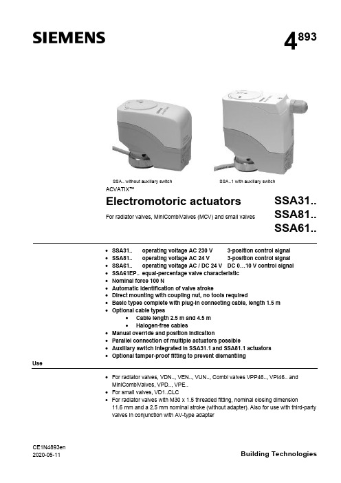
CE1N4893en 2020-05-11Building Technologies4893SSA.. without auxiliary switch SSA..1 with auxiliary switchACVATIX™Electromotoric actuatorsFor radiator valves, MiniCombiValves (MCV) and small valvesSSA31..SSA81..SSA61..·SSA31.. operating voltage AC 230 V 3-position control signal ·SSA81.. operating voltage AC 24 V 3-position control signal ·SSA61.. operating voltage AC / DC 24 V DC 0…10 V control signal ·SSA61EP.. equal-percentage valve characteristic ·Nominal force 100 N·Automatic identification of valve stroke·Direct mounting with coupling nut, no tools required·Basic types complete with plug-in connecting cable, length 1.5 m ·Optional cable types·Cable length 2.5 m and 4.5 m ·Halogen-free cables·Manual override and position indication·Parallel connection of multiple actuators possible·Auxiliary switch integrated in SSA31.1 and SSA81.1 actuators ·Optional tamper-proof fitting to prevent dismantlingUse·For radiator valves, VDN.., VEN.., VUN.., Combi valves VPP46.., VPI46.. and MiniCombiValves, VPD.., VPE..·For small valves, VD1..CLC· For radiator valves with M30 x 1.5 threaded fitting, nominal closing dimension11.6 mm and a 2.5 mm nominal stroke (without adapter). Also for use with third-party valves in conjunction with AV-type adapter2/10SiemensCE1N4893enSmart InfrastructureBuilding Technologies2020-05-11· For modulating or 3-position control in heating systems, chilled ceilings and terminal units.Type summaryTypereference Operating voltage Run time at 50 HzControl signalConnecting cableAuxiliary switchSSA31AC 230 V150 s3-position1.5 m SSA31/001)no cable SSA31.1 1.5 m YesSSA81AC 24 V1.5 m SSA81/001)no cable SSA81.1 1.5 m YesSSA61AC / DC 24 V 34 s DC 0...10 V1.5 m SSA61/001)no cable SSA61EP 2) 1.5 m SSA61EP/002)no cable1)For available cable lengths or terminal block connectors refer to "Accessories", page 42)With equal-percentage valve characteristicTypereference DescriptionOperating voltage Control signalASY3L25Connecting cable 2.5 mAC 230 V3-positionASY3L45Connecting cable 4.5 m ASY8L25Connecting cable 2.5 m AC 24 V ASY8L45Connecting cable 4.5 mASY8L45HF Connecting cable 4.5 m, halogen-free, VDE 0207-24ASY6L25Connecting cable 2.5 m AC / DC 24 V DC 0...10 V ASY6L45Connecting cable 4.5 m ASY6L45HF Connecting cable 4.5 m, halogen-free, VDE 0207-24ASY98Retaining screw for terminal block connectors. Included in ASY99 and ASY100.ASY99Terminal block connector for 3-position actuators SSA81../00ASY100Terminal block connector for DC 0…10 V modulating actuators SSA61/00AL40Tamper-proof fitting to prevent dismantling of actuators Adapter typefor third-party valves Adapter type for third-party valves AV51Beulco old (M30x1.0)AV56Giacomini AV522)Comap AV57Herz AV53Danfoss RA-N (RA2000)AV58Oventrop old (M30x1.0), till 2002AV54Danfoss RAVL AV592)Vaillant AV55Danfoss RAV AV60TA, till 20021)AV61Markaryd (MMA)1) No adapter required for type TBV-C 2)While stocks lastOrdering Type Stock no.DescriptionQuantity SSA81/00SSA81/00Electromotoric actuator 2ASY8L45ASY8L45Connecting cable2Actuators, valves and accessories are packed separately. Items are suppliedindividually packed.Overview tables, see page 9.AccessoriesExample:DeliveryRev.-No.3/10SiemensCE1N4893en Smart Infrastructure2020-05-11Equipment combinationsk vs = nominal flow rate of cold water (5...30 °C) through the fully open valve (H 100)at a differential pressure of 100 kPa (1 bar)V & = Nominal volume flow at 0.5 mm strokeTo ensure trouble-free operation of third-party valves with the SSA.. actuator, the valves must satisfy the following requirements:·Threaded connections with coupling nut M30 x 1.5·Nominal force F £ 100 N ·Dimension x x > 9.0 mm ·Dimension y y £ 14.5 mmFunction / mechanical designWhen the actuator is driven by DC 0…10 V control voltage or by a 3-position signal, it produces a stroke which is transmitted to the valve stem.The description of operation in this document applies to the valve versions which are fully open when de-energized (NO).·Voltage at Y1:Stem retracts Valve opens ·Voltage at Y2:Stem extends Valve closes ·No voltage at Y1 and Y2:Actuator maintains its current position· The valve opens / closes in proportion to the control signal at Y.· At DC 0 V, the valve is fully closed (A à AB).· When power supply is removed, the actuator maintains its current position.1)Actuator is calibrated to 2.5 mm stroke of VPI46.15.L06S t r o k e 2,5 m m ((c a l i b r a t e d )1)22.51.510.500246810control signal Y [V]Type reference Valve type k vs [m 3/h]V&[l/h]PN class Data sheet VDN.., VEN.., VUN..Radiator valves 0.09…1.41PN 10N2105, N2106VPD.., VPE..MCV radiator valves 25…483N2185VD1..CLC Small valves 0.25…2.60N2103VPP46.., bi valves 30…4001PN 25N4855For other radiator valves with type AV.. adapters refer to "Type summary / accessories"Radiator valves (M30 x 1.5) from other manufacturers, without adapter:· Heimeier · Crane D981..· TA-Type TBV-C · Oventrop M30 x 1.5 (from 2001)· MNG · Junkers · Honeywell-Braukmann · Cazzaniga · Beulco (new)Valves from othermanufacturers3-position control signalSSA31.. / SSA81..DC 0...10 V control signalSSA61, SSA61/004/10SiemensCE1N4893enSmart InfrastructureBuilding Technologies2020-05-11Combi valves VPI46../VPP46.. in combination with SSA61EP.. have an equal-percentage characteristics.· The valve opens / closes in equal percentage ratio to the control signal at Y.· At DC 0 V, the valve is fully closed (A à AB).· When power supply is removed, the actuator maintains its current position.1)Actuator is calibrated to 2.5 mm stroke of VPI46.15L06S t r o k e 2,5 m m (c a l i b r a t e d )1)2.42.51.510.500246810control signal Y [V]·Plastic housing·Locking-proof, maintenance-free gear train·Manual override with hexagonal socket wrench 3 mm ·Reduced power consumption in the holding positions·Load-dependent switch-off in the event of overload and in stroke end positions·Parallel operation of 6 SSA31.., 24 SSA81.. and 10 SSA61..possible, provided the controllers’ output is sufficient ·Terminal block connectors for customer made cables available (only for use with AC 24 V and AC / DC 24 V actuators)·Connecting cables with AC 24 V and AC 230 V connectors cannot be mixed up·Halogen-free cables availableAccessoriesAdapter types AV51 to AV61 are available for mounting the SSA.. actuators on third-party radiator valves as shown under "Type summary/accessories", page 2.1xtighten gentlyType ASY98 to secure the cable connector. Included in ASY99 and ASY100.The cable connector snaps into position,but can be additionally secured with the retaining screw.DC 0...10 V control signal SSA61EP,SSA61EP/00Features and advantagesAdapter type AV.. for third-party valves Tamper-proof fitting AL40Retaining screw ASY985/10SiemensCE1N4893en Smart Infrastructure2020-05-11For special cable lengths of the AC / DC 24 V actuators.·Type ASY99 for 3-position actuators SSA81../00·Type ASY100 for DC 0…10 V modulating actuators SSA61/00The terminal block connectors are supplied complete with mounting instructions (74 319 0385 0).Notes The actuators must be electrically connected in accordance with local regulations (refer to "Connection diagrams", page 9).Regulations and requirements to ensure the safety of people and property must be observed at all times!The permissible temperatures (refer to "Technical data", page 7) must be observed.The connecting cable of the actuator may come into contact with the hot valve body,provided the temperature of the valve body does not exceed 80 °C.Actuator types SSA 31.1 and SSA81.1 have a built-in auxiliary switch. The switch cannot be fitted in other actuators later.Mounting instructions (Ref. 74 319 0497 0) are enclosed in the product packaging.The actuator and valve are assembled with the coupling nut; no tools or adjustments are required.The actuator must be fitted in position 1 with the power disconnected (refer also to "Manual override", page 6):·Position the actuator and tighten the coupling nut manually ·Do not use any tools such as wrenches·Avoid lateral pressure or (cable) tension on the mounted actuator!In the case of actuators without a connecting cable (SSA../00), the separately orderedCrimp ferrule on stripped wire of connecting cable.When commissioning, check the wiring and the functioning of the actuator and auxiliary switch, if fitted.·Actuator stem extends (from position 1 to 0): Valve closes ·Actuator stem retracts (from position 0 to 1): Valve opens During commissioning and whenever the operating voltage is switched on,the SSA61.. runs a self-calibration routine. (Valve stroke 0® Max.stroke ® Setpoint).Never intervene manually in this process.ON0 %EngineeringMountingOrientationInstallationCommissioningTerminal block connectors ASY99ASY1006/10SiemensCE1N4893enSmart InfrastructureBuilding Technologies2020-05-11The second or third attempt at calibration occurs automatically after an 8-minute delay.After three failed calibration attempts the actuator stem remains in the extended position and the radiator valves are closed.For valves with strokes < 1.5 mm, the actuator/valve combination locks after three failed calibration attempts.The new Siemens type VDN.., VEN.. and VUN.. radiator valves have in all 1.5 mm stroke.A 3 mm hexagonal socket wrench can be used to move the actuator to any position.However, if a control signal from the controller is present, then this takes priority in determining the position.To retain the manually set position, unplug the connecting cable or switch off the operating voltage and the control signal.2.5 mm stroke5.5 mm strokeThe actuators are maintenance-free.When carrying out service work on the plant, following must be noted:·Turn power off (e.g. remove the plug)·If necessary, disconnect electrical connections from the terminals·The actuator must be commissioned only with a correctly mounted valve in place!SSA.. actuators cannot be repaired; the complete unit must be replaced.DisposalWarrantyThe technical data given for these applications is valid only when the actuators are used with the Siemens valves listed under "Equipment combinations", page 2.The use of the SSA.. actuators in conjunction with third-party valves invalidates any warranty offered by Siemens Building Technologies / HVAC Products.Note: Correctcalibration is only possible ·with valve·stroke > 1.5 mmOperationNoteManual overrideMaintenance!Repair7/10SiemensCE1N4893en Smart Infrastructure2020-05-11Technical dataPower supplyControlFunctional dataElectrical connectionsNorms and directivesDimensions /weight Housing colors 1)Provided the controller output is sufficient2)The documents can be downloaded from /bt/download8/10SiemensCE1N4893enSmart InfrastructureBuilding Technologies2020-05-11General ambient conditionsOperation EN 60721-3-3Transport EN 60721-3-2Storage EN 60721-3-1Environmental conditions Class 3K3Class 2K3Class 1K3Temperature +1...+50 °C –25...+70 °C –5...+50 °C Humidity 5...85 % r.h.< 95 % r.h. 5...95 % r.h.Connecting cableConnection terminalsY2Y1G4864Z 15Control signal CLOSE Control signal OPENSystem potential AC 24 VG0Y G4864Z 16System neutralControl signal DC 0...10 V System potential AC/DC 24 VFactory setting: 50 %0...50 % Q11® Q1250...100 % Q11® Q14The switching point can be adjusted by turning the switching cam with a screwdriver (see Mounting Instructions).Recommended connecting cable: H03VV-F, 2x0.5…0.75 mm 2.ASY3L.. with SSA31..ASY8L.. with SSA81..ASY6L.. with SSA61..ASY99for SSA81..ASY100for SSA61..Terminals for auxiliary switchesSSA31.1, SSA81.19/10SiemensCE1N4893en Smart Infrastructure2020-05-11Connection diagramsN Controller Y ActuatorL System potential AC 230 V NSystem neutralY1, Y2Control signal OPEN, CLOSE Q1, Q2Controller contactsN Controller YActuatorSP, G System potential AC 24 V SN, G0System neutralY1, Y2Control signal OPEN, CLOSE Q1, Q2 Controller contactsN Controller YActuatorSP, G System potential AC 24 V SN, G0System neutral Y Control signalSSA31..SSA81..SSA61..10/10SiemensCE1N4893enSmart InfrastructureBuilding Technologies2020-05-11DimensionsDimensions in mm8377484893M 0172.59M30 x 1,54893M 0298.5834889.5M30 x 1,59Revision numbersType reference Valid from Rev.-No.Type reference Valid from Rev.-No.SSA31K SSA61K SSA31/00K SSA61/00KSSA31.1K SSA81K SSA81/00K SSA81.1KActuator without auxiliary switch SSA31..SSA81..SSA61..Actuator with auxiliary switch SSA31.1..SSA81.1..Issued bySiemens Switzerland LtdBuilding Technologies Division International Headquarters Theilerstrasse 1a 6301 Zug SwitzerlandTel. +41 41-724 24 24/buildingtechnologies © Siemens Switzerland Ltd, 2005Technical specifications and availability subject to change without notice.。
Spears 电动阀门电动驱动器选择手册说明书

Actuated Valves TechnicalElectric Actuator SelectionMade in the U.S.A.Suitable for Oil-Free air handling to 25 psi, not for distribution of compressed air or gasSee Spears ® Product Sourcebook for product offerings Page 6Revised: 12-20-2022Step 2: Actuator Code SelectionSpears ® actuated valves are available with either electric or pneumatic motors. Actuators are pre matched to each type and size of valve with proper operating torque and cycle time. Additional actuator accessories are selected and are factory installed on the Actuated Valve Package in Step 3 instructionsSelect the applicable options from either the Electric Actuators (Selection Table 4) or Pneumatic Actuators (Selection Table 5) and enter the designated Actuator Code portion of the package part number.Table 4: ELECTRIC ACTUATORS (Voltage-Enclosure Rating-Manual Override-Duty Cycle)ACTUATOR CODE Optional Control Number (not used on basic packages)1-2-3-4-56-7-8-910-11-12Reserved for Valve Reserved for SizeDuty Cycle (see note 3)1 = 25%2 = 75%3 = 100%4 = 50%5 = 70% (custom only)6 = 80% (custom only)7 = 40%8 = 60%9 = 20%Voltage (see note 1)A = 115 VAC 60 Hz B = 230 VAC 60 Hz C = 230 VAC 3-phase 50 Hz (EU)D = 230 VAC 3-phase 60 Hz E = 24 VAC F = 12 VDC G = 24 VDC L = 460 VAC 3-Phase 50 Hz (EU)M = 460 VAC 3-Phase 60 Hz N = 460 VAC 1-Phase 60 Hz R = 415 VAC 3-Phase 50 Hz S = 230 VAC 50 Hz (EU)T= 575 VAC 3-Phase 60Hz (EU)U = 115 VAC 50 Hz (EU)V = 208 VAC 3-Phase 60 Hz X = Single Indicator Switch Only (see note 2)Y = Double Indicator Switch Only (see note 2)Z = Actuator Bracket Only (see note 2)1 = 480 VAC 50 Hz2 = 480 VAC 60 Hz3 = 480 VAC 3-Phase 50 Hz4 = 480 VAC 3-Phase 60 Hz5 = 380 VAC 3-Phase 60 Hz6 = 12 VAC 60 Hz7 = 440 VAC 3-Phase 60 HzManual Override (see note 4)0 = None1 = Basic Manual Override2 = Declutchable Manual Override3 = Spring Return Open with Declutchable Manual Override (see not 5)4 = Spring Return Close with Declutchable Manual Override (see note 5)5 = Spring Return Open no override (see note 5)6 = Spring Return Close no override (see note 5)7 = RCE Battery Backup Actuator8 = Spring Return Open with Basic Manual Override (see note 5)9 = Spring Return Close with Basic Manual Override (see note 5)A = Super Capacitor Open with Basic Manual OverrideB = Super Capacitor Close with Basic Manual OverrideC = Super Capacitor Open with Declutchable Manual OverrideD = Super Capacitor Close with Declutchable Manual OverrideEnclosure1 = NEMA4 5 = NEMA 4 Double Powder Coated 9 = AWWA C=NEMA 6P,prolonged2 = NEMA4x 6 = NEMA 4x Double Powder Coated A = NEMA 7 Modulation enclosure submersion at a limited depth.(for 1/2"-2" modulated Ball /Butterfly)3 = NEMA 77 = NEMA 7 Double Powder Coated D=NEMA 84 = NEMA 98 = NEMA 9 Double Powder Coated B = NEMA 6Notes:1 - 460 VAC available on Butterfly Valves only.2 - Bracket & Indicator Switch Only part numbers do not allow any other options(must be Z000, Y000, or X000).3 - Standard Duty Cycles vary according to valve type and size as indicated in chart below. Standard Duty Cycles can be upgraded only.Note: 50% duty cycle available on non-standard, special order actuators only.Valve Type Size Range 25% Duty Cycle 75% Duty Cycle 100% Duty CycleBall Valve 1/2" - 2"XBall Valve 2-1/2" - 4"XButterfly Valve 1-1/2" - 10"XButterfly Valve 12" - 24"XDiaphragm Valve 1/2" - 8"X4 - Basic Manual Override is standard on Ball Valve sizes 1/2" - 3" with Declutchable Manual Override as an option.Declutchable Manual Override is standard on Ball Valve sizes 4" & larger and all Butterfly Valves.Standard Gate Valve and Diaphragm Valve packages have no override with Declutchable Manual Override as an option. Spring return notavailable on electric Diaphragm valves.5 - Electric Spring Return Actuators come standard with no type of override. Need to verify if either Declutchable Manual Override or BasicManual Overrides are available in all applications.。
(完整word版)控制阀选型原则)
控制阀选型原则调节阀的节流原理和流通能力当流体经过调节阀时,由于阀芯、阀座间流通面积的局部缩小,形成局部阻力,使流体在此处产生能量损失,这个损失的大小通常用阀前后的压差来表示. 当调节阀口径一定,即调节阀接管截面积A一定,且P1—P2不变时,阻力系数ζ减小,流量Q则增大,反之ζ增大则Q减小,所以调节阀的工作原理就是由输入信号的大小、改变阀芯的行程,从而改变流通面积达到调节流量的目的。
C称为流通能力,与阀芯、阀座的结构、阀前后的压差、流体性质等因素有关.必须在规定了—定的条件后,再描述调节阀的流通能力。
我国所用流通能力C的定义为:在调节阀全开,阀前后压差为1kgf/cm2,介质重度为1gf/cm3时,流经调节阀的流量数。
例如:一个C值为32的调节阀就是表示当阀全开,阀前后压差为1kgf/cm2时,每小时能通过的水量为32m3。
一、由工艺或用户提供相关资料:1、被控制流体的种类:(3种)液体、气体和蒸汽对于液体应考虑黏度的修正,当液体粘度过高时,其雷诺数下降,改变了流体的流动状态,在计算控制阀流通能力时,必须考虑粘度校正系数。
对于气体,应该考虑其可压缩性。
对于蒸汽,要考虑饱和蒸汽和过热蒸汽。
2、流体的温度、压力根据工艺介质的最大工作压力来选定控制阀的公称压力时,必须对照工艺温度条件综合选择,因为公称压力是在一定基准温度下,依据强度确定的,其允许最大工作压力必须低于公称压力。
例如:对于碳钢阀门,当公称压力PN1.6MPa,介质温度在200℃时,最大耐压力为1。
6 MPa;当250℃时,最大耐压力为1。
5 MPa;当400℃时,最大耐压力为0。
7 MPa。
对于压力调节系统,还要考虑其阀前取压、阀后取压和阀前后压差,在进一步来选择阀的形式。
3、流体的粘度、密度和腐蚀性根据流体的粘度、密度和腐蚀性来选择不同形式的阀门以便满足工艺的要求。
对于高粘度、含纤维介质常用O型和V型球阀;对于腐蚀性强的易结晶的流体常用阀体分离型的阀体。
电动控制阀门配件和选项说明书
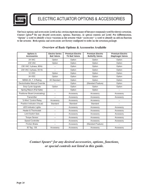
The basic options and accessories listed in this section represent many of the most commonly used for electric actuation. Contact Spears® for any desired accessories, options, functions, or special controls not listed. For differentiation, “Option” is used to identify a basic variation in the actuator while “Accessory” is used to identify an add-on function to the actuator. Both options and accessories are factory con¿ gured to order on the actuation package.Overview of Basic Options & Accessories AvailableOptions & Accessories Electro SeriesBall ValvesPremium ElectricTU Ball ValvesPremium ElectricButterÀ y ValvesPremium ElectricDiaphragm Valves24 VAC Option Option Option Option230 VAC Option Option Option Option 230 VAC 3-phase, 60Hz--Option Option Option 230 VAC 3-phase, 50 Hz--Option Option Option12 VDC Option Option Option Option24 VDC Option Option Option OptionNEMA 4X, 7, 9 Rating4X Standard Option Option Option Declutchable Manual Override--Option(Standard Feature)Option Duty Cycle Upgrade Option Option Option Option Spring Return (Fail Safe)--Option Option--Positioner Board (modulating)--Accessory Accessory Accessory Transmitter--Accessory Accessory Accessory “2-Wire” Control Relay Accessory Accessory Accessory--Position Indicator (Visual)Standard Standard Standard--LED Indicator Lights--Accessory Accessory Accessory Heater & Thermostat--Accessory Accessory Accessory Limit Switch Sets--Accessory Accessory Accessory Torque Sensor--Accessory Accessory Accessory Speed Controller--Accessory Accessory Accessory Friction Brake--Accessory(Standard Feature)--ID Tag - SS Accessory Accessory Accessory AccessoryContact Spears® for any desired accessories, options, functions,or special controls not listed in this guide.Standard (2-position) Actuator Voltage OptionsV oltage options and maximum current draw (Lock Rotor Current) are listed for each type and size of valve with 2-position (open/close) actuation. See Modulating Service Option for variable position actuators and applicable voltages.Voltage OptionsLoc Roter AMP Electro-50Loc Roter AMP Electro-10012 VAC 2.4N/A 24 VAC 2.17.8230 VAC .5 1.512 VDC .3.224 VDC .2.2115 VAC.61.9Electro Series Ball Valves (All 1/2" - 2")Voltage OptionsSize Max. Current24 VAC1/2" - 2" 2.52-1/2" - 4"3.26"3.2230 VAC 1/2" - 6".3812 VDC 1/2" - 2" 2.892-1/2" - 6"4.024 VDC1/2" - 2" 2.442-1/2" - 6"3.2True Union 2000 Ball ValvesVoltage OptionsSize Max. Current24 VAC1-1/2" - 6" 3.28" - 10" 3.212"20230 VAC1-1/2" - 10".3812" 2.812 VDC 1-1/2" - 6" 4.08" - 10" 4.012"1424 VDC1-1/2" - 6" 3.28" - 10" 3.212"20Butter À y ValvesVoltage OptionsSize Max. Current24 VAC 1/2" - 4" 3.2230 VAC 1/2" - 4".3812 VDC 1/2" - 2" 4.02-1/2" - 4"N/A 24 VDC1/2" - 2" 2.62-1/2" - 4"N/ADiaphragm ValvesEnclosure NEMA Rating OptionsStandard enclosures are NEMA 4. The following NEMA ratings are available for all True Union Ball Valves, ButterÀ y Valves and Diaphragm Valves (see NEMA Ratings in Terminology & De¿ nitions for additional description detail).Enclosure Rating General DescriptionNEMA 4Watertight & Dust TightNEMA 4X Watertight & Dust Tight with corrosion resistanceNEMA 7Explosion Proof (class I, division 1, groups A, B, C, D)NEMA 9Explosion Proof (class II, division 1, groups E, F, G)Declutchable Manual Override OptionAvailable for all Premium Electric actuated valves.Valve Type Standard Actuator Package Declutchable Option Available True Union 2000 Ball Valve 1/2" - 3"Manual YesTrue Union 2000 Ball Valve 4" - 6"Declutchable(standard) ButterÀ y Valve - All Declutchable(standard)Diaphragm Valve - All None YesSlightly different than straight manual override, Declutchable Manual Override disengages the actuator gear train for manual operation of the valve. Valves with this option have a hand wheel mounted on top of the actuator for manual valve operation. Spears® True Union Ball Valves and ButterÀ y valves include either straight Manual or Declutchable Override as part of standard actuation package, as indicated in the Table.Duty Cycle Upgrade OptionAvailable for all Premium Electric actuated valves. Upgrades in duty cycles use heavier motors to handle heat build up from extended operation. Standard duty cycles are listed for each valve type and are upgradeable to extended cycles as indicated. Valves with Modulating Service option are equipped with a minimum of a 75% duty cycle as standard. Contact Spears® if a higher Duty Cycle is requiredValve Type Size Range Standard Duty Cycle Upgrade To 75%Electro Series1/2" - 2"25%X True Union Ball Valve1/2" - 2"75%--True Union Ball Valve2-1/2" - 4"25%X ButterÀ y Valve1-1/2" - 10"25%XButterÀ y Valve12"100%--Diaphragm Valve1/2" - 6"25%XSpring Return (Fail Safe) OptionAvailable for all Premium Electric actuated Ball valves and ButterÀ y valves. An internal spring in the actuator is con¿ gured to either open or close upon loss of power supply. Special gear clutch uncouples motor during spring return. Operation can be speci¿ ed as either fail-open when spring return open is desired or fail-close when spring return close is desired.“2-Wire” Control RelayAvailable for Premium Electric actuated Ball valves and Butter À y Valves. Special control switch setup operates the valve through internally mounted control relay. Valve opens when control switch is open and closes when control switch is closed. Uses 4-wire connection with 2 wires to line voltage and 2 wires to SPST control switch. Available either in normally closed or normally open con ¿ guration.Positioner Board (Modulating)Available for all Premium Electric actuated valves. Modulation is used to control or throttle À ow in response to an external control signal. An internally mounted, solid state positioner board accurately controls valve position from open to close. Available in the actuator voltages and input signals shown Note: Modulating Service option includes Duty Cycle Upgrade to a minimum of 75%.LED Position Indicator LightsAvailable for all Premium Electric actuated valves. LED(light emitting diode) red/green indicator lights mounted on actuator enclosure to designate open/closed position.Heater and ThermostatAvailable for all Premium Electric actuated valves. Mounted internally, heats the inside of the enclosure in low temperature environments to prevent condensation and keep internal lubricants À uid. The thermostat activates the heater when the enclosure internal temperature drops below the set point. There are a variety of thermostatsavailable and a set point must be speci ¿ ed at the time of ordering.Modulating ActuatorVoltageInput Signal115 VAC 4-20mA, 0 - 5 VDC, 0 - 10 VDC 230 VAC 4-20mA, 0 - 5 VDC, 0 - 10 VDC 24 VAC 4-20mA, 0 - 5 VDC, 0 - 10 VDC 24 VDC4-20mA, 0 - 5 VDC, 0 - 10 VDCAuxiliary Limit Switches (Provide in sets of 2)Available for all Premium Electric actuated valves. Additional internally mounted single pole double throw limit switch (SPDT) independent from the motor switches. Typically used for indicator lights, auxiliary equipment, etc. Actuation packages accept from 1 to 2 additional sets of auxiliary limit switches as indicated. When ordering replacement sets, specify hole size of cams (either 3/8" or 1/2").Speed ControllerAvailable for all Premium Electric actuated valves.Internally mounted relays (not shown) and solid state timer allow variable control of valve cycle time (speed) by selecting combinations of ON time and OFF time options. Rate may be slowed, but cannot exceed the standard cycle time speci ¿ ed for the actuator.Torque SensorAvailable for all Premium Electric actuated valves.Internally mounted sensor is adjustable to speci ¿ c torque limits to avoid damage to valve in the event of blockage..Valve Type Auxiliary Limit Switch SetsTrue Union Ball Valve1/2" - 2"12-1/2" - 3"14" - 6"2Butter À y Valve1-1/2"12" - 10"212"2Diaphragm Valve - all SizesTransmitterAvailable for all Premium Electric actuated valves. The Transmitter module is normally used with the 4-20mA Positioner Board and the board’s power supply. It can also be used as a stand alone feedback transmitter when no position controller is used, but will require an external power supply for stand alone application. This internally mounted module provides a 4-20mA output signal directly proportional to the Positioner Board feedback potentiometer. This signal can be used by a remote instrument to monitor or display actuator position. Zero and span adjustments allow adjustment of the Transmitter’s 4-20mA signal to correspond with the zero and span positions set by the Positioner Board.Friction BrakeAvailable for all Premium Electric actuated valves. Internally mounted device which is used to eliminate mechanical “coast” of the actuator motor at the end of its cycle. Brakes are standard on all electrically actuated ButterÀ y Valves and not applicable to Diaphragm Valves.Custom ID TagStainless steel valve/actuator ID Tag imprinted to user speci¿ ed identi¿ cation criteria. Each tag is 1/2" x 3" and accommodates up to 3 lines of text, maximum of12 characters and spaces per line.。
阀门选用标准及要求
阀门选用标准及要求阀门选型一般要求阀体常用材质阀门内件常用材质阀门密封面常用材料及适用温度闸阀平板闸阀锲式闸阀截止阀柱塞阀球阀节流阀旋塞阀蝶阀止回阀隔膜阀蒸汽疏水阀安全阀减压阀一般要求:根据我集团各产品生产工艺的特点,针对各种介质,作阀门选用的一般要求如下:第一条:阀门选用的第一原则是阀门的密封性能要符合介质的要求。
即内漏要符合标准GB /T13927-1992《通用阀门压力试验》,外漏则是根本不允许的。
第二条:正确选择阀门的类型。
阀门类型的正确选择是以选用者对整个生产工艺流程需要的综合估计为先决条件的,在选择阀门类型的同时,选用者应首先了解每种阀门的结构特点和性能。
一般阀门的类型选择如中低压蒸汽选用铜密封面的截止阀,DN200以上的蒸汽用闸阀;循环水总管上用蝶阀,支管上用衬胶闸阀;低压空气总管上用蝶阀,支管上用截止阀;一般液态物料用球阀等。
第三条:确定阀门的端部连接。
在螺纹连接、法兰连接、焊接端部连接中,前两种最常用,其中螺纹连接形式的价格比法兰连接形式低得多,一般为较小口径阀门,应首先选用。
第四条:阀门主要零件材质的选择。
选择阀门主要零件的材质,首先应考虑到工作介质的物理性能(温度、压力)和化学性能(腐蚀性)等。
同时还应了解介质的清洁程度(有无固体颗粒)。
除此之外,还要参照国家和使用部门的有关规定的要求。
正确合理地选择阀门的材料可以获得阀门最经济的使用寿命和最佳的性能。
(附表1-1、1-2、1-3) 阀体材料选用顺序大致按照铸铁-碳钢-不锈钢,密封圈材料选用顺序:橡胶-铜-合金钢-F4。
第五条:确定流经阀门的流量。
第六条:压力等级选用按照由低到高顺序。
附表1-1阀门壳体常用材质附表1-2阀门内件常用材质附表1-3阀门密封面常用材料及适用温度各种类型阀门的选用标准及要求如下:闸阀特点:密封性能好,流体阻力小,且有一定的调节性能;但尺寸大、结构复杂,加工困难、密封面易磨损,不易维修,启闭时间长。
多回转阀门电动装置

多回转阀门电动装置型号:DZW10、DZW20﹑DZW30﹑DZW60、DZW90﹑DZW120、DZW180﹑DZW250、DZW500输出力矩:100~5000N.m供电电源:220V 、380V、415V、660V品牌:常州凯文1:概述多回转阀门电动执行机构,通称为DZW/Z型。
适用于启闭件做直线运动的阀门,如闸阀,截止阀,隔膜阀,闸门,水闸阀等。
用于阀门的开启,关闭或调节。
是对阀门实现远控,集控和自控的必不可少的驱动装置。
他们具有功能全,性能可靠,控制系统先进,体积小,重量轻,使用维护方便等特点。
广泛用于电力,冶金,石油,化工,造纸,脱硫除尘,污水处理等行业。
多回转电动执行机构有:户外型,隔爆型,整体型,调节型,整体隔爆型等。
按连接型式,分为转矩型和推力型。
2:型号表示方法型号示例1:DZW30I-18/50:表示电动执行机构为多回转,输出转矩300N.m(30Kgf.m),电站型接口,输出转速18r/min,最大转圈数50,户外型。
2:DZB45T-24/120S:表示电动执行机构为多回转,带手动二级减速装置,输出转矩450N.m(45Kgf.m) 推力型接口,输出转速24r/min,最大转圈数120,隔爆型/3:DZBT120-24/80:表示电动执行机构为多回转,输出转矩1200N.m(120Kgf.m),输出转速24r/min, 最大转圈数80圈,隔爆整体调节型。
3:工作环境和主要技术参数1:电源:常规:单相220V,三相380V,远程DC24V(50HZ)特殊:单相110V,三相415V,660V,(50HZ,60HZ)2:工作环境:●环境湿度:-20~+60℃(特殊订货-60~+80℃)。
●相对湿度:≤95%(25℃时)●户外型用于无易燃/易爆和无腐蚀性介质的场所;●隔爆型产品有dI和dIIBT4两种,dI适用于煤矿非采掘工作面;dIIBT4用于工厂,适用于环境为IIA,IIB级T1-T4组的爆炸性气体混合物。
7-5 KIP 电磁阀选型说明书
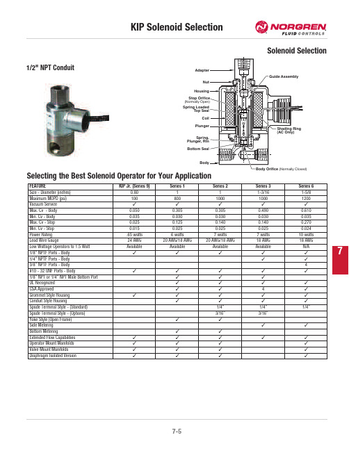
7Selecting the Best Solenoid Operator for Your ApplicationStop(NormallyTopPlunger,Bottom1/2"NPT ConduitFEATURE KIP Jr.(Series9)Series1Series2Series3Series6Size-Diameter(inches)0.80111-3/161-5/8Maximum MOPD(psi)100800100010001200Vacuum Service¤¤¤¤¤Max.Cv-Body0.0500.3050.3050.4900.610Min.Cv-Body0.0350.0300.0300.0300.035Max.Cv-Stop0.0250.1250.1400.1400.270Min.Cv-Stop0.0150.0250.0250.0250.024Power Rating.65watts6watts7watts7watts10wattsLead Wire Gauge24AWG20AWG/18AWG20AWG/18AWG18AWG18AWGLow Wattage Operators to1.5Watt Available Available Available Available N/A1/8"NPTF Ports-Body¤¤¤¤¤1/4"NPTF Ports-Body¤¤3/8"NPTF Ports-Body4#10-32UNF Ports-Body¤¤¤¤¤1/8"NPT or1/4"NPT Male Bottom Port¤¤¤UL Recognized¤¤¤¤CSA Approved¤¤4¤Grommet Style Housing¤¤¤¤¤Conduit Style Housing¤¤¤¤Spade Terminal Style-(Standard)1/4"1/4"1/4"Spade Terminal Style-(Options)3/16"3/16"Yoke Style(Open Frame)¤¤Side Metering¤¤Bottom Metering¤¤Extended Flow Capabilities¤¤¤¤¤Operator Mount Manifolds¤¤¤¤Valve Mount Manifolds¤¤¤¤Diaphragm Isolated Version¤¤¤¤7U 240115-0251-24VDC*CoilsAll standard KIP valves are supplied with a Class “B”dry tape wound coil construction with 24"black leads,P/N (01)in the ordering system,unless otherwise specified.When using this chart below note the available housing styles and the series in which coils are available.The following chart shows all coil options readily available,for other options in OEM quantities consult KIP.Non-standard voltages,leadwire lengths,other lead wire types and colors,may require minimum quantities.KIP standard voltages:12VDC,24VDC,24/60,120/60,110/50,220/50,240/60.Lead wire type -AWG 20on Series 1and 2AWG 18on Series 1and 2with free standing molded coil AWG 18on Series 3and 6Coil classification -Class B =130°C or 266°F Class F =155°C or 311°F Class H =180°C or 356°F**For Class H coils change the second digit to a 3.Consult KIP for minimum order quantities.***Full wave rectification7 KIP Part Identification Numbering(PIN)System For ValvesThe KIP part number provides information about every aspect of the product it represents.The first letter is an optional prefix which identifiesUL recognized,oxygen or low wattage.The following numbers identify series,ports,housing style,material,valve function,orifice,seal,coil construction and coil temperature,in that order.The numerical value for each respective category represents one of multiple options.Where possible,the organization of this KIP catalog presents information in the order of the part identification number.You may use the number as a guide to finding information within the catalog.The following chart is the key to understanding the KIP Part Identification Number.UYABCDG7=#10-32UNF8=3/8"NPT(f)1=Grommet2=1/2"NPT Conduit3=Yoke(d)4=Yoke w/bracket(d)7=Grommet w/bracket9=Slotted(e)0=Slotted w/bracket(e)BunaFluorocarbon®Neoprene®Low temperature BunaPolyurethane(2WNC only)Teflon®(2WNC only)Neoprene W®Ethylene Propylene(EPR(Food Grade)be usedmolded coil(e)=Slotted housing(used with31&51spade coiloption),available in Series2,3&ed withmolded coil61in Series2&3,and41in Series1.(f)=Available in Series6,2WNC only.(g)=Available in Series1&2diaphragm only.® Teflon and Neoprene are registered trademarks of E.I. Dupont De Nemours Co.*Available in Series 1, 2 & 3 for 2-Way Normally Closed, 3-Way Normally Closed and 3-Way Multi-Purpose functions.7Series 6Note: Series 6 manifold mount 3-Way valves have a 1/4" NPTF adapter as standard. 1/8" NPTF available upon request.** Manifold Mount valve has maximum 400 MOPD rating for UL recognition.† These valves are supplied with 3/8" NPTF ports.Series 6Orifice Diameter Cv Factor MOPD (psi)Standard Valve Body Grommet Manifold Mount**Valve Body-Grommet Stainless Steel BrassBodyStop BodyStop 1/8" NPTF 1/4"NPTF 1/8" NPTF1/4"NPTF Stainless Steel Brass 2-Way Normally Open1/320.03510006410206510206411206511206610206611203/640.0506006410216510216411216511216610216611211/160.0953506410226510226411226511226610226611225/640.1402506410236510236411236511236610236611233/320.2001756410246510246411246511246610246611241/80.2951006410256510256411256511256610256611252-Way Nomally Closed1/320.03512006410106510106411106511106610106611103/640.05010006410116510116411116511116610116611111/160.0955006410126510126411126511126610126611125/640.1403006410136510136411136511136610136611133/320.2002006410146510146411146511146610146611141/80.2951506410156510156411156511156610156611155/320.3701106410166510166411166511166610166611163/160.435606410176510176411176511176610176611171/40.610306410186510186411186511186610186611183/80.9005—681019†—681119†——3-Way Normally Open1/321/320.0350.0254006410506510506411506511506610506611503/643/640.0500.0652506410516510516411516511516610516611511/161/160.0900.1152006410526510526411526511526610526611525/645/640.1350.1801756410536510536411536511536610536611533/323/320.1800.2101256410546510546411546511546610546611541/81/80.2750.240856410556510556411556511556610556611555/321/80.3700.240506410566510566411566511566610566611563/161/80.4550.240356410576510576411576511576610576611571/41/80.6500.240156410586510586411586511586610586611583-Way Normally Closed(For free vent,change fifth digit from 4 to 3)1/321/320.0350.0253006410406510406411406511406610406611403/643/640.0500.0652506410416510416411416511416610416611411/161/160.0900.1152006410426510426411426511426610426611425/645/640.1350.1801756410436510436411436511436610446611443/323/320.1800.2101256410446510446411446511446610456611451/81/80.2750.240856410456510456411456511456610466611465/321/80.3700.240506410466510466411466511466610476611473/161/80.4550.240306410476510476411476511476610486611481/41/80.6500.24015641048651048641148651148--3-Way Multi-Purpose1/321/320.0350.0252756410606510606411606511606610606611603/643/640.0500.0652006410616510616411616511616610616611611/161/160.0900.1151756410626510626411626511626610626611625/645/640.1350.1801256410636510636411636511636610636611633/323/320.1800.2101006410646510646411646511646610646611641/81/80.7500.240606410656510656411656511656610656611655/321/80.3700.240406410666510666411666511666610666611663/161/80.4550.240256410676510676411676511676610676611671/41/80.6500.240156410686510686411686511686610686611687Operator StandardBracket DimensionsManifold Mount ValveAB C D E F G H Series6 1.64(42)G- .97 (25)C- .80 (20)1.79(46)2.48(63)1.03(26)1.58(40)1-32 UN1/8-27 NPTF or 1/4-18NPTFA B C D E F Series 62.13 (54)1.97 (50).20 (5)2.63 (67)2.15 (55)2.68 (68)AB C D E F m n r Series 6 1.62(41)G-1.73 (44) 2.55(65)3.23(82)1.03(26)1.58(40)1/2 20UNF.31(8)1/8-27 NPTFor 1/4-18 NPTFC-1.56 (40)。
Q型阀门电动装置操作说明书.doc

更多企业学院:《中小企业管理全能版》183套讲座+89700份资料《总经理、高层管理》49套讲座+16388份资料《中层管理学院》46套讲座+6020份资料《国学智慧、易经》46套讲座《人力资源学院》56套讲座+27123份资料《各阶段员工培训学院》77套讲座+ 324份资料《员工管理企业学院》67套讲座+ 8720份资料《工厂生产管理学院》52套讲座+ 13920份资料《财务管理学院》53套讲座+ 17945份资料《销售经理学院》56套讲座+ 14350份资料《销售人员培训学院》72套讲座+ 4879份资料Q型阀门电动装置QTYPE ELECRIC VALVE ACTUATORS使用说明书Instruction Manual常州凯文阀门控制设备有限公司目录一、概述二、型号表示方法三、技术条件和性能参数四、结构五、电气控制原理和接线六、外形及安装尺寸七、安装八、调整九、使用注意事项十、故障原因及排除方法一、概述Q型阀门电动执行机构适用于蝶阀、球阀、旋塞阀等部分回转阀门和类似设备,该产品结构紧凑、起动转矩大、控制精度高、功能齐全、性能可靠、安装调整简便。
Q型为一体结构(区别于叠加结构)90度回转产品,它与阀门配套组成电动阀门,用来驱动和控制阀门的开启和关闭,操作人员既能在控制室内远距离对阀门进行控件,亦能在现场进行操作。
该产品广泛应用于给排水、供热、电站、化工、食品、纺织、造纸、制药、船舶、钢铁、煤炭等工业部门。
按使用环境分:Q为户外型、QB为隔爆型、QZ为整体型、QT为整体调节型、QBZ为整体防爆型、QBT 为整体防爆调节型。
转矩范围:50N.m -- 50000N.m本产品的性能符合 JB/T8528-1997 《普通型阀门电动装置技术条件》的规定。
防爆型的性能符合GB3836.1-83 《爆炸性环境用防爆电气设备通用要求》, GB3836.2-83 《爆炸性环境用防爆电气设备隔爆型电气设备“d”》及 JB/T8529-1997 《隔爆型阀门电动装置技术条件》的规定。
阀门选型手册

阀门选型手册-阀门选型的步骤和依据阀门选型手册-阀门选型的步骤和依据在流体管道系统中,阀门是控制元件,其主要作用是隔离设备和管道系统、调节流量、防止回流、调节和排泄压力。
由于管道系统选择最适合的阀门显得非常重要,所以,了解阀门的特性及选择阀门的步骤和依据也变得至关重要起来。
阀门行业到目前为止,已能生产种类齐全的闸阀、截止阀、节流阀、旋塞阀、球阀、电动阀、隔膜阀、止回阀、安全阀、减压阀、蒸汽疏水阀和紧急切断阀等12大类、3000多个型号、4000多个规格的阀门产品;最高工作压力为600MPa,最大公称通径达5350mm,最高工作温度为1200℃,最低工作温度为-196℃,适用介质为水、蒸汽、油品、天然气、强腐蚀性介质(如浓硝酸、中浓度硫酸等)、易燃介质(如笨、乙烯等)、有毒介质(如硫化氢)、易爆介质及带放射性介质(金属钠、-回路纯水等)。
阀门承压件材质铸铜、铸铁、球墨铸铁、高硅铸铁、铸钢、锻钢、高、低合金钢、不锈耐酸钢、哈氏合金、因科镍尔、蒙乃尔合金、双相不锈钢、钛合金等。
并且能够生产各种电动、气动、液动阀门驱动装置。
面对如此众多的阀门品种和如此复杂的各种工况,要选择管道系统最适合安装的阀门产品,我以为,首先应了解阀门的特性;其次应掌握选择阀门的步骤和依据;再者应遵循选择阀门的原则。
1.阀门的特性一般有两种,使用特性和结构特性。
使用特性:它确定了阀门的主要使用性能和使用范围,属于阀门使用特性的有:阀门的类别(闭路阀门、调节阀门、安全阀门等);产品类型(闸阀、截止阀、蝶阀、球阀等);阀门主要零件(阀体、阀盖、阀杆、阀瓣、密封面)的材料;阀门传动方式等。
结构特性:它确定了阀门的安装、维修、保养等方法的一些结构特性,属于结构特性的有:阀门的结构长度和总体高度、与管道的连接形式(法兰连接、螺纹连接、夹箍连接、外螺纹连接、焊接端连接等);密封面的形式(镶圈、螺纹圈、堆焊、喷焊、阀体本体);阀杆结构形式(旋转杆、升降杆)等。
阀门选型的步骤和依据 吴片刚

阀门选型的步骤和依据吴片刚摘要:针对阀门选型的步骤和依据,结合理论实践,在简要阐述阀分类的基础上,分析了阀门选型的具体步骤和依据。
最后通过深入分析得出阀门选型中遵循科学合理和步骤和依据才能提高阀门的使用周期和安全性的结论,希望对相关单位有一定帮助。
关键词:阀门选型;分类;步骤;依据引言:阀门是流体输送过程中的主要控制部件,在具体应用过程中,阀门具有截止、导流、调节、分流、稳压、溢流泄压等功能。
近年来,随着我国科学技术的发展,阀门的种类不断增加,其功能和作用也快速发展。
在具体应用过程中,如何选择合适的阀门也变的非常重要,本文结合理论实践,对阀门选型的步骤和依据做了如下分析。
1、阀门的种类1.1根据用途和作用分类根据阀门用途和作用的不同大体上可以分为以下几大类:第一类,截断类,其主要作用是截断或者接通介质流,比如:截止阀、球阀、蝶阀等;第二类,止回类,主要作用是组织介质发生倒流;第三类,调节类,主要作用是调节流体介质的压力和流量,比如:减压阀、调压阀、节流阀等都属于调节阀;第四类,安全类,当流体介质的压力超过规定限值以后,来排放多余的介质,确保管道系统和设备安全性;第五类,分配类,其主要作用改变流体介质的流向或者分配介质,确保流体能够顺利通过管道,最常见的有三通旋塞、分配阀等;第六类,特殊用途类,包括疏水阀、放空阀等1.2根据压力不同的分类当阀门的工作压力在标准大气压以下时,称之为真空阀;当公称压力在1.6MPa以下时,称之为低压阀门;当公称压力在2.6~6.4MPa时,称之为中压阀门;当公称压力在10.0~80.0MPa之间时,称之为高压阀门;当公称压力超过100MPa时,称之为超高压阀门。
1.3按照介质的温度分当通过阀门的介质达在450℃以上时,称之为高温阀门;当介质温度在120℃~450℃时,称之为中温阀门;当介质的温度在40℃~120℃时,称之为常温阀门;当介质温度在-40℃~100℃时,称之为低温阀门;当通过阀门的介质温度在-100℃以下时,称之为超低压阀门。
智能控制电动调节阀选型原则
智能掌控电动调整阀选型原则智能掌控电动调整阀选型原则电动调整阀重要性能指标有:基本误差、回差、死区、额定行程偏差、泄漏量、密封性、耐压强度、外观、额定流量系数、固有流量特性、耐振动、温度、长期工作牢靠性、防爆、阻尼特性、电源电压变化影响、环境温度变化影响、绝缘电阻、绝缘强度等。
指标的要求和试验方法均与气动调整阀相同或相像,其中基本误差、回差、死区、泄漏量、密封、外观、阻尼特性、电源电压变化影响、绝缘电阻为出厂试验项目,后3项性能指标的要求和试验方法为:电动调整阀的调整阀重要由阀体、套筒、阀瓣、阀杆等零件构成。
套筒和阀瓣上都开有节流孔通过阀瓣在阀座内回转来更改过流面积,调整流量。
配ZKJ型或其它型电动角行程执行器可实现遥控和自动掌控。
因电动调整阀牢靠、全功能、超轻型等优点,被应用地越来越广泛,在一些相对较小的工厂,只需几台电动调整阀,配以调整器或PLC等掌控系统,就可实现自动化掌控。
下面我们来了解一下电动调整阀的重要性能特点,实在如下:调整阀在现代工厂的自动掌控中特别紧要。
通过接受掌控单元输出的掌控信号,从而更改介质流量,压力,温度,液位和其他工艺参数,可以说:掌控阀是工艺环路中的最后一道关卡!因此,如何选择正确的调整阀,以达到的掌控效果?这成为一个关键问题。
调整阀固有流量特性的“选择原理”掌控阀的选择应依据掌控系统的特性,干扰源和S(阀阻比)值三个方面综合考虑。
一、智能掌控电动调整阀选型原则一般选择原则1. 阀上的压差变化很小,给定值变化很小,过程的重要变量变化很小,并且S 0.75掌控对象,选择直线流量特性是适当的。
2. 在缓慢的生产过程中,当S 0.4时,直线流量特性。
3. 在要求大可调范围,管路系统压力损失大,阀门开度和压力差变化较大的场合,应选择等百分比流量特性。
4. 快速的生产过程,假如对系统的动态过程不太了解,建议选择等百分比的流量特性。
5. 也可以依据以前的阅历依据下表选择流量特性。
阀门电动装置选型要点 阀门电动装置如何操作

阀门电动装置选型要点阀门电动装置如何操作阀门电动装置是实现阀门程控、自控和遥控不可缺少的驱动设备,其运动过程可由行程、转矩或轴向推力的大小来掌控。
行业阀门电动装置有侧紧要的作用。
电动阀门比气动阀门电动装置是实现阀门程控、自控和遥控不可缺少的驱动设备,其运动过程可由行程、转矩或轴向推力的大小来掌控。
行业阀门电动装置有侧紧要的作用。
电动阀门比气动、液动阀门使用更为普遍,因此在采购阀门电动装置的时候,对阀门电动装置进行合理的选型使电动执行装置具有更高的牢靠性和安全性。
阀门电动装置选型要点:一、依据阀门类型选择电动装置:阀门种类繁多,各种阀门的工作原理也不一样,依照阀门类型概括一下几种电动装置:1、角行程电动装置(转角360度);此类电动装置适用于闸阀、截止阀等。
3、直行程电动装置(直线运动);此类电动装置适用于单座调整阀、双座调整阀等。
二、依据生产工艺掌控要求选择电动装置:电动装置的掌控模式一般分为开关型(开环掌控)和调整型(闭环掌控)两大类。
1、开关型电动装置一般实现对阀门的开或关掌控,阀门要么处于全开位置,要么处于全关位置,此类阀门不需对介质流量进行精准明确掌控。
特别值得一提的是开关型电动装置因结构形式的不同还可分为分体结构和一体化结构。
选型时必需对此做出说明,不然常常会发生在现场安装时与掌控系统冲突等不匹配现像。
2、调整型电动装置不仅具有开关型一体化结构而精准明确调整介质流量。
因的功能,它还能对阀门进行精准明确掌控,从篇幅有限其工作原理在此不作认真说明。
下面就调整型电动装置选型时需注明的参数做简要说明。
三、依据阀门操作力矩选择阀门电动装置:阀门正常启闭所需的扭力由阀门口径大小、工作压力等因素决议,但因阀门厂家加工精度、装配工艺有所区分,所以不同厂家生产的同规格阀门所需扭力也有所区分,即使是同个阀门厂家生产的同规格阀门扭力也有所差别,当选型时执行器的扭力选择太小就会造成无法正常启闭阀门,因此电动装置必需选择一个合理的扭力范围。
阀门选型配置技术手册
阀门选型配置技术手册为了规范给排水、消防水、空调水系统常用阀门的选型与配置,明确相关阀门的技术要求,指导各项目公司对阀门集采清单列项的选用,特制订本技术手册,包含的阀门类别有:蝶阀、闸阀、浮球阀、止回阀、过滤器、倒流防止器、减压阀、泄压阀、截止阀、软接头。
本手册适用范围为万达广场各业态。
一、根据各管道系统以及阀门特点的不同,确定阀门配置标准如下,并附图示。
A、钢制阀门(球墨铸铁或铸钢类)适用于公称直径DN≥65的管道系统,其中一)公称压力1.6MPa钢制阀门1、给水系统(生活冷水系统、中水系统):1)泵房外管道上:暗杆式弹性座封闸阀;2)泵房内管道上: 明杆式弹性座封闸阀;3)生活水箱补水处:100X遥控浮球阀;4)水泵出水端:300X缓闭止回阀;5)水泵进水端:Y型过滤器;6)生活水泵进出水处:不锈钢软接头;7)中水水泵进出水处:橡胶软接头;8)分区供水需减压时,选用200X减压阀;9)市政给水接驳处水表附近:倒流防止器。
2、生活热水系统锅炉房及换热站一次水侧:1)热水锅炉进出水管道的第一个阀门:铸钢截止阀;2)循环水泵进出水处:不锈钢软接头;3)循环水泵出水端的止回阀可根据设计要求进行选定。
4)热水管道上:法兰式硬密封蝶阀;换热器后二次水侧:同给水系统;3、排水系统1)污水泵出水处:橡胶瓣止回阀+明杆式弹性座封闸阀。
4、消防水系统(包括消火栓系统、喷洒系统、消防水泡系统):1)泵房外消防管道上:中心线对夹式软密封蝶阀;2)泵房内、水泵出水端:中心线法兰式软密封蝶阀;泵房内、水泵进水端:明杆式弹性座封闸阀;3)消防水池补水处:100X遥控浮球阀;4)分区供水需减压时,选用200X减压阀;5)消防水泵出水端:H41X消声止回阀;6)消防水泵出水端若需要泄压,选用500X泄压阀;7)消防水泵进水端:Y型过滤器;8)消防水泵进出水处:橡胶软接头。
5、空调水系统1)制冷站外空调水管道上:中心线对夹式软密封蝶阀;2)制冷站内空调水管道上:中心线法兰式软密封蝶阀;3)空调水泵出水端:300X缓闭止回阀;4)空调水泵进水端:Y型过滤器;5)空调水泵或空调机组(新风机组)进出水处:橡胶软接头。
企业信用报告_常州凯文阀门控制设备有限公司
目录一、企业背景 (5)1.1 工商信息 (5)1.2 分支机构 (5)1.3 变更记录 (5)1.4 主要人员 (6)1.5 联系方式 (6)二、股东信息 (7)三、对外投资信息 (7)四、企业年报 (7)五、重点关注 (8)5.1 被执行人 (8)5.2 失信信息 (9)5.3 裁判文书 (9)5.4 法院公告 (9)5.5 行政处罚 (9)5.6 严重违法 (9)5.7 股权出质 (9)5.8 动产抵押 (9)5.9 开庭公告 (10)5.11 股权冻结 (10)5.12 清算信息 (10)5.13 公示催告 (10)六、知识产权 (10)6.1 商标信息 (10)6.2 专利信息 (11)6.3 软件著作权 (11)6.4 作品著作权 (11)6.5 网站备案 (11)七、企业发展 (11)7.1 融资信息 (11)7.2 核心成员 (11)7.3 竞品信息 (12)7.4 企业品牌项目 (12)八、经营状况 (12)8.1 招投标 (12)8.2 税务评级 (12)8.3 资质证书 (12)8.4 抽查检查 (13)8.5 进出口信用 (13)8.6 行政许可 (13)一、企业背景1.1 工商信息企业名称:常州凯文阀门控制设备有限公司工商注册号:320404000092237统一信用代码:91320404693339778F法定代表人:陆丽雯组织机构代码:69333977-8企业类型:有限责任公司(自然人投资或控股)所属行业:批发业经营状态:开业注册资本:888万(元)注册时间:2009-08-12注册地址:钟楼区五星街道新丰村委花园路24号营业期限:2009-08-12 至无固定期限经营范围:阀门驱动装置、阀门及配件、电力成套辅机设备的制造(制造限分支机构经营)、销售;普通机械及配件、金属材料、建筑材料、非危险化学品化工原料的销售。
(依法须经批准的项目,经相关部门批准后方可开展经营活动)登记机关:常州市钟楼区市场监督管理局核准日期:2019-11-211.2 分支机构截止2022年02月11日,爱企查未找到该公司的分支机构内容。
- 1、下载文档前请自行甄别文档内容的完整性,平台不提供额外的编辑、内容补充、找答案等附加服务。
- 2、"仅部分预览"的文档,不可在线预览部分如存在完整性等问题,可反馈申请退款(可完整预览的文档不适用该条件!)。
- 3、如文档侵犯您的权益,请联系客服反馈,我们会尽快为您处理(人工客服工作时间:9:00-18:30)。
700 Q350 Z20 Q500 Z30 Z45 Z60 Z90 Z90 Z180 Z250
400 Z30
800 900 1000 1100 1200 1400 1600 1800 Q400 Q500 Z45 Z60 Z60 Z90 Z120 Z180 Z20 Z30 Z45 Z60 Z60 Z90 Z90 Z120 Z180 Z180 Z60 Z90 Z90 Z90 Z120 Z180 Z250 Z350 Z90 Z90 Z90 Z120 Z180 Z250 Z350 Z90 Z120 Z120 Z180 Z250 Z350 Z120 Z180 Z180 Z250 Z350 Z180
15
20
25
32
40
50
65
80
100
125
150
200
10
Z5
Z5
Z5
Z5
Z5
Z5
Z5
Z 10 Z 15 Z 20 Z 30 Z 45
16
Z5
Z5
Z5
Z5
Z5
Z5
Z 10 Z 20 Z 20 Z 30 Z 45 Z 60
25
Z5
Z5
Z5
Z5
Z5
Z 10 Z 10 Z 20 Z 20 Z 30 Z 45 Z 60
900 Z 90 Z 120 Z 120
1000 Z 90 Z 120 Z 180
1200 1400 Z 120Z Z180 Z 180 Z 180 Z 250 Z250
250
Z 60 Z 120 Z 180
300
Z 90 Z 180 Z 250
350
Z 120 Z 250
400
Z 250 Z 350
6 Z 5 Z 5 Z 5 Z 10 Z 15 Z 15 Z 15 Z 20 Z 20 Z 30 Z 30 Z 45 Z 45 Z 60 Z 60 Z 60
10 Z 5 Z 10 Z 10 Z 10 Z 15 Z 15 Z 15 Z 20 Z 20 Z 30 Z 45 Z 45 Z 60 Z 60 Z 60 Z 90
Q5
Q5
Q10
Q20
Q30
Q60
Q90 Z10
Q120 Q200 Q300 Z45 Z15 Z20 Z30
25
Q5
Q5
Q5
Q5
Q5
Q10
Q20
Q30
Q60
Q90
Q120 Q200 Q250 Q400 Z45 Z10 Z20 Z20 Z30
40
Q5
Q5
Q5
ቤተ መጻሕፍቲ ባይዱ
Q5
Q10
Q10
Q20
Q30
Q60
Q90
Q120 Q250 Q400 Q500 Z60 Z10 Z20 Z30 Z45
Z10 Z10 Z15 Z20 Z30
Z60 Z60 Z90 Z120 Z120 Z90 Z90 Z120 Z120 Z120 Z120
80 100 125 150 200 250 300 350 400 450
1
Q5 Q5 Q10
2.5 Q10 Q10 Q10
6
Q10 Q10 Q20
10 Q10 Q10 Q20
型号
Z962Y-P54140V
Z962YP54140V Z962YP54170V
Z962YP54170V
公称通径 DN(MM) 250 125 175 225 100 125 150 175 225 175 225 250 300
压力 14 14
17 17
电装型号
DZW250 DZW90 DZW120 DZW180 DZW90 DZW90 DZW120 DZW120 DZW180 DZW120 DZW80 DZW250 DZW350
压力 10 14 17
电装型号
DZW60 DZW60 DZW30 DZW45 DZW60 DZW0 DZW45 DZW60 DZW90 DZW120
联系人:刘治国 13401350750
400 Z45 Z60 Z90 Z90 Z120
450 Z60 Z60 Z90 Z90 Z180
500 Z60 Z90 Z120 Z120 Z180
600 Z90 Z120 Z180 Z180 Z250
700 Z120 Z180 Z250 Z250 Z350
电动装置与通风蝶阀力矩选配表
通 50 60 80 100 125 150 200 250 300 350 400 450 500 600 700 800 900 1000 1100 1200 1400 1600 1800 2000 径
16 Q10 Q20 Q20
25 Q20 Q20 Q30
40
Q60 Q60
64
Q60 Q120
100
Q120 Z10
电动装置与刀型闸阀选配表
Q10
Q20
Q20
Q30
Q60
Q60
Q90 Q200 Z10 Q200 Z15
Q20
Q60
Q60
Q90
Q90 Z10 Q200 Z10 Q200 Z15 Q250 Z15 Q300 Z20
40 Z 5 Z 10 Z 10 Z 15 Z 20 Z 20 Z 30 Z 30 Z 45 Z 60 Z 90 Z 120 Z 180 Z 250 Z 500 Z 800
64 Z 10 Z 10 Z 10 Z 20 Z 20 Z 30 Z 30 Z 45 Z 60 Z 90 Z 120 Z 180 Z 250 Z 500 Z 500 Z 800
型号
Z960Y-320 Z962Y-320
Z960YP54100V
Z962YP54100V
Z962YP54140V
公称通径 DN(MM) 125 175 225 176 225 250 300 150 225 250 125 175 225
压力 PN(mpa) 32
10 10 14
电装型号
DZW15 DZW20 DZW30 DZW45 DZW60 DZW90 DZW120 DZW45 DZW60 DZW 90 DZW120
型号
J961Y-320 J961YP54100V
公称通径 DN(MM) 10 20 25 32 50 65 80 100 50 65
压力 PN(mpa)
32 10
电装型号
DZW120 DZW180 DZW250 DZW90 DZW120 DZW120 DZW60 DZW120 DZW120 DZW120 DZW90 DZW120 DZW180
电动装置与阀门选配表
电动装置与闸阀选配表
40 50 65 80 100 125 150 200 250 300 350 400 450 500 600 700
2.5 Z 5 Z 5 Z 5 Z 5 Z 10 Z 10 Z 15 Z 15 Z 20 Z 20 Z 30 Z 30 Z 45 Z 45 Z 60 Z 60
力矩 Z10 Z10 Z10 Z10 Z10 Z10 Z15 Z20 Z20
500 Q200 Z15 Q200 Z15 Q300 Z20 Q400 Z20 Z60
Z60
Z60
Z90
Z120
300 Z20
600 Q250 Z15 Q400 Z20 Q500 Z30 Z45
Z90
Z80
Z60
Z180
Z250
64
Q5
Q5
Q5
Q10
Q10
Q20
Q30
Q60
Q90 Z10
Q200 Q200 Q300 Q500 Z45 Z10 Z10 Z20 Z30
Z60
100 Q5
Q5
Q5
Q10
Q20
Q20
Q60
Q90
Q200 Q200 Q300 Q500 Z45 Z10 Z15 Z20 Z30
Z45
Z120
800 Z 60 Z 90 Z 120 Z 350 Z 500
Q60 Q90 Q90 Q120 Q200 Q150 Q250 Q500 Z45 Z60 Z60 Z10 Z15 Z20 Z30 Z45
Q90
Q90
Q120 Q200 Q250 Q400 Q500 Z45 Z10 Z15 Z20 Z20 Z30
Z60
Z90
Z90
Q120 Q120 Q200 Q400 Q500 Z60
25
175
225
Z960Y-300 225
30
300
电动装置与高温压焊接截止阀选配表
型号
公称通径 压力
DN(MM)
20
25
32
50
65
25
80
100
50
65
80
20
100
电装型号
DZW120 DZW180 DZW180 DZW120 DZW120 DZW180 DZW90 DZW120 DZW120 DZW120 DZW180 DZW250 DZW500
Z 30
Z 30
Z 45
Z 90
Z 120 Z 180
320
Z5
Z 10
Z 20
Z30
电动装置与软密封球阀力矩选配表
Z 45 Z 45 Z 90 Z 120 Z 250 Z 500
15 20 25 32 40 50 65 80 100 125 150 200 250 300 350
16
Q5
Q5
Q5
Q5
2.5 Q10 Q10 Q10 Q10 Q10