CY-2010A数字风速仪说明书
sY_2010A说明书
sY_2010A说明书
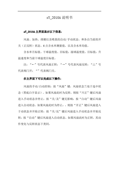
sY_2010A主界面显示以下信息:
风扇、加热、排潮以及喷蒸的自动/手动状态,和各自当前的开关(正反转)状态。
6点含水率测量值,以及含水率均值。
含水率月标值。
干球温度值、目标值:湿球温度值、目标值:升温速度和当前干球温度目标值。
注:“←”号代表风扇正转:“→”号代表风扇反转:“△”号代表阀门开:“”代表阀门关。
在主界面下可以完成以下操作:
风扇的手动/白动控制:按“风扇”键,风扇状念兰处于选中状念(黑底白字显示)。
如果风扇此时为反转,则按“川正”键后风扇进入手动状态并停止:按“关/及”键无影响:按“白动”键后风扇进入自动状态。
如果风扇此时为停止:,则按“开正”键后风扇进入于动状态并开始正转:按“关/反”键后风扇进入手动状态并开始反转:按“自动”键后风扇进入自动状态。
如果风扇此时为正转,其动作变化与反转状态下类同。
Met One 010C 风速传感器用户手册说明书

MODEL010CWIND SPEED SENSOROPERATION MANUALMet One Instruments, IncCorporate Sales & Service: 1600 NW Washington Blvd. Grants Pass, OR 97526 Tel (541) 471-7111 Fax (541) 471-7116******************1.0 GENERAL INFORMATION1.1 The 010C Wind Speed Sensor uses a durable, three-cup anemometer assembly andsolid-optical link with a 40-slot chopper disk to produce a pulsed output whosefrequency is proportional to wind speed. An internal heater reduces moisture forextended bearing life. This sensor is usually used in conjunction with the 191 Cross arm Assembly. The sensor may be used with a translator module, or used directlywith a variety of data loggers.1.2 The Sensor Cable has a quick-connect connector with vinyl jacketed, shielded cable.Cable length is given in -XX feet on each cable part number. A 1953-XX cable isused with translators having terminal strip connections.Table 1-1Model 010C Wind Speed Sensor SpecificationsPerformance CharacteristicsMaximum Operating Range 0-60 meters/sec or 0-125 mphStarting Speed 0.27 meters/sec or 0.6 mphCalibrated Range 0-50 meters/sec or 0-100 mphAccuracy ±1% or 0.15 mphTemperature Range -50︒C to +85︒CResponse Distance constant less than 5 ft of flow**The distance traveled by the air after a sharp-edged gust has occurred for theanemometer rate to reach 63% of the new speed. Distant constant less than 15ft of flow with optional 010C-1 aluminum cupset.Electrical CharacteristicsPower Requirements 12 VDC at 10 mAOutput Signal 11-volt pulseOutput Impedance 100 ohms maximumHeater Power Requirement 12 VDC at 350 mAStandard Cable Length 300’ maximum (consult factory if longercable is to be used for special requirements) Physical CharacteristicsWeight 1.1 poundsFinish Anodized aluminumMounting Use with 191 CrossarmCabling 1953-XX Cable (XX is cable length in feet)Optional AccessoriesA. External heater and power supply for extreme low temperature operation.B. Ice Skirt for extreme icing environments.C. Aluminum cup assembly.2.0 INSTALLATION2.1 The 010C Wind Speed InstallationA. Mount the cup assembly and secure with the Allen head set screw, check to seethat the cup assembly rotates freely.B. Install the sensor in the end of the Model 191 Crossarm Assembly (the endwithout the bushing).C. Tighten the locking set screw. Do not over-tighten. Apply a small amount ofsilicone grease to set screws to prevent freezing in adverse environments.D. Connect the cable assembly to the keyed sensor receptacle and tape it to themounting arm.2.2 WiringA. The cable assembly contains five wires. Typical wiring hookup is shown inFigure 2-1.No Connection White/Brown ShieldElectrical ConnectorView looking at connector pins. (Pins are also identified on connector).2.3 Lightning ProtectionA. Weather sensors are sensitive to direct or nearby lightning strikes. A well-grounded metal rod or frame should be placed above the sensor installation. Inaddition, the shield on the signal cable leading to the translator must beconnected to a good earth ground at the translator end and the cable routeshould not be vulnerable to lightning.3.0 OPERATIONAL CHECK-OUT AND CALIBRATION3.1 010C Wind Speed Sensor Check-OutA. Spinning the anemometer cup assembly will produce a series of pulses (40pulses per revolution). To verify sensor output, monitor this signal with either thetranslator module, data logger, or an oscilloscope. (Refer to Frequency vs. WindSpeed Table 3-1). Spinning the hub of the wind speed transmitter without thecup assembly mounted and allowing it to coast to a stop will give a goodindication of threshold performance; a jerky or sudden stop indicates damage tobearings, bent drive shaft, or obstruction in the light chopper.B. Inspect the cup assembly for loose cup arms or other damage. The cupassembly cannot change calibration unless a mechanical part has come loose orhas been broken. If a cup arm is loose or broken the calibration of the sensormay be affected.C. If the sensor heater is used, check internal heater operation by sliding sensorcover down and touching the housing behind the printed circuit board. Thehousing should feel warmer than the adjoining metal parts. The sensor has abuilt-in heater that is designed to provide a raise in the internal temperature,providing a small amount of positive pressure. This heater requires as external12 V (@500ma) power supply.FREQUENCY vs WIND SPEED FOR 010 SENSORTABLE 3-1Transfer FunctionsMiles per hour: Meters per second:rpm = 16.767 * (V mph - 0.6) rpm = 37.522 * (V m/s - 0.27) V mph = (rpm / 16.767) + 0.6 V m/s = (rpm / 37.522) + 0.27 f Hz = (V mph - 0.6) / .08946 f Hz = (V m/s - 0.27) / 0.039976 V mph = V m/s * 0.44704 V m/s = V mph / 0.447044.0 MAINTENANCE AND TROUBLESHOOTING4.1 General Maintenance Schedule*6 – 12 Month Intervals:A. Inspect sensor for proper operation per Section 4.2.B. Replace wind speed sensor bearings in extremely adverse environments perSection 4.5.12 – 24 Month Intervals:A. Recommended complete factory overhaul of sensor.*Schedule is based on average to adverse environments.Table 4-1010C Wind Speed Sensor TroubleshootingSymptom Probable Cause Solution Refer toNo wind speed output Loss of supplyvoltage Check translator +12supply & connectingcablesFigure 2-1Faulty integratedamplifierReplace circuit board Section 4.5Faulty diodes,D1, D2Replace circuit board Section 4.5Faulty detector Replace detector Section 4.6No wind speed outputbelow 2-5 mphBad bearing(s) Replace bearing(s) Section 4.4Faulty detector Replace detector Section 4.6Wind speed signal drops ouas speed increasesFaulty detector Replace detector Section 4.64.2 010C Wind Speed Sensor: 6 – 12 Month Periodic ServiceA. At the crossarm assembly, disconnect the quick disconnect plug from the sensor(leave the cable secured to the crossarm) and remove the sensor from thecrossarm assembly.B. Loosen the set screw holding the cup assembly. Support the rotating hub of thesensor with one hand and pull the anemometer cup assembly free.C. Visually inspect the anemometer cups for cracks and breaks. Also, make surethat each arm is securely attached to the cup assembly hub.D. Slide the sensor cover down to expose the light-chopper disc assembly, lightsource, detector, and circuit board.E. Inspect the interior of the sensor for any signs of corrosion and/or dust buildup.F. Inspect the light-chopper for cracks, and make sure that all slots are free ofcorrosion.G. Inspect the signal-conditioning module for cracks and corrosion around solderedconnections.H. Rotate the sensor hub assembly to ensure that it turns freely and that the sensorbearings are not damaged. Make sure the light-chopper assembly is notcontacting the light source and detector.I. Apply a small amount of silicone lubricant. (Dow-Corning DC-33 or equivalent) tothe sensor O-ring seals; slide the cover up over the sensor and wipe off anyexcess lubricant.J. A moisture vent is located on the base of the sensor; make sure that this vent is clear.K. Re-install sensor according to installation procedure (Section 2.0); verify proper operation using procedures in Section 3.0.4.3 010C Wind Speed Sensor Maintenance (Refer to 010C Sensor Assembly Drawing)The following procedures require a relatively clean, dry work area, a source of 12VDC power at approximately 20 mA, and an oscilloscope (DC to 10 KHz minimumrange required.4.4 Sensor Bearing Replacement. (Refer to 010C Sensor Assembly Drawing)A. Remove sensor from tower and remove cup assembly (1). Refer to Section 4.2.B. Disassemble sensor and remove old bearings (6).1. Slide the sensor cover (16) down to expose the light-chopper discassembly (10), detector assembly (12) and circuit board (18).2. Loosen both special set screws on the shaft of the light chopper assembly(11).3. Support the light-chopper assembly (10) with one hand and slowly pullthe rotating hub/shaft assembly (2) out of the column (8).4. Remove the shield (4) and slinger (5) from the column (8).5. Remove the light-chopper assembly (10) from the sensor housing, beingcareful not to damage the slots located between the light-chopper holderand the lower bearing.6. Insert the lower end of the rotating hub/shaft assembly into the upperbearing, cock it slightly to one side and push out the lower bearing.7. Insert a right-angle type of tool, such as an Allen wrench, into the upperbearing; cock it slightly to one side and remove the bearing.8. Clean dirt from bearing bores, using a cotton swab and alcohol.C. Install the new bearings and assemble the sensor.1. Install new upper and lower bearings in the column (8). Bearings shouldslide easily into bearing bores.2. Install a slinger and shield (4, 5) on the column assembly. Use new partsif old ones are damaged or corroded.3. Insert the rotating hub shaft (2) into the column assembly (8), through theshield (4), slinger, and upper bearing, until it starts to protrude through thelower bearing.4. Support the light-chopper assembly (10) with one hand and slowly pushthe rotating hub shaft into it until the shaft almost touches the bottom.5. Tighten both special set screws on the light-chopper assembly; do notover tighten as the set screw tips will damage the shaft.6. Rotate the sensor hub assembly (2) to ensure that it turns freely and thatan endplay of about .005” exis ts.7. Hold sensor vertically and make sure that the light-chopper assembly (10)is not contacting the detector assembly (12).8. Apply small amount of silicone lubricant (Dow-Corning DC-33 orequivalent) to the sensor O-rings (9); slide the cover (16) up over thesensor and wipe off any excess lubricant.D. Replace cup assembly and re-install (refer to Section 2.0)4.5 1200-1 Circuit Board Assembly Replacement (Refer to 010C Assembly Schematic)A. Remove sensor from tower and remove cup assembly (refer to Section 4.2).B. Slide the sensor cover (16) down to expose the light-chopper disc assembly (10),detector assembly (12), and circuit board (18).C. Remove two screws (17) holding circuit board assembly (18) and lift circuit boardaway from sensor housing.D. Note color of wires and then unsolder wires to detector assembly from circuitboard and three wires from connector (19).E. Install new circuit board assembly by reversing above procedure.4.6 Detector Assembly Replacement Refer to 010C Assembly Schematic)NOTE: 010C sensors SN M10560 and later use 520253 photodetector. Oldersensors use 1074 photodetector assemblies.A. Remove sensor from tower and remove cup assembly. Refer to Section 4.2.B. Slide the sensor cover (16) down to expose the light-chopper disc assembly (10),detector assembly (12) and circuit board (18).C. Remove two screws (17) holding circuit board assembly (18) and lift circuit boardaway from sensor housing.D. Note color of wires and then unsolder wires to detector assembly from circuitboard (18).E. Remove two screws (20) holding detector assembly (12) and remove assembly.F. Install new detector assembly by reversing above procedures.4.7 010C Wind Speed Sensor Repair and Recalibration ServiceThe factory provides fast, economical service for the user. This repair andcalibration service includes disassembly and detailed inspection of all movingmechanical parts and electronic components.Service includes replacement of bearings, regardless of apparent condition, andfunctional test of sensor. Replacement of the following items is also included: O-rings, shield and slinger, shaft, set screws. Other components will be replaced as required. Only charges for additional materials will be added to the basic service charge.Table 4-2Replacement 010C Parts ListRef No.U Description Part No.1 Cup Assembly Lexan - 2672Aluminum – 2672-1 2 Hub/Shaft Assy. 26584 Shield 10095 Slinger 10106 Bearing 10559 O-ring 72012010 Chopper Wheel Assembly 220211 Set Screw 60125012 Photo Detector 520253*13 Heater Clamp 48010014 Heater 80508016 Sensor Cover 267517 PCBA Mounting Screws 60124018 PCBA 1200-120 Detector Assembly Mounting Screws 60127022 Standoff 86005023 Integrated Amplifier 62030024 Nut, Hex, Kep 4-40 60040025 Screw FH 82︒ 4-40 x 3/8 60133026 Screw FH 82︒ 4-40 x ¼ 601240NOTE: 010C sensors SN M10560 and later use the black 520253 photodetector. Earlier sensors use the white 1074 photodetector assemblies.。
风速风向仪说明书

推荐几个调试方法:
首先要确保设备接线正确,且严格合乎规范。
终端电阻法: 在最后一台485设备的485+和485-上并接420欧姆的终端电阻来改善通讯质量.注意:许多485布线文档推荐使用120终端匹配电阻、但是使用120欧电阻值太小,会导致功耗过大,且会拉低485+和485-之间的压差,影响信号的传输,因此我们推荐使用较大的几百欧的终端匹配电阻。
PH计算机风速软件用于读取PH风速风向仪测量的当前风速风向,下载风速风向仪里面记录存储的风速风向历史数据,并将历史数据保存在MS ACCESS数据库中,通过表格或曲线视图对数据进行分析,计算机软件还可以对风速风向仪的实时时钟、历史数据记录间隔等参数进行设置。
PH风速风向仪软件操作方法:
使用时请在软件设备种类种选择风速风向仪(ACPH-4),其它使用会在我公司软件光盘中详解。
报警设置:
当风速超过设定的风速上限时,继电器吸合蜂鸣器响报警,该功能为选配功能。
系统时间设定:
使用“↑”键更改系统时间,使用“↓”键光标向右移动,使用“确认”键保存设置并自动保存新的时间。
记录间隔:
用来设置风速风向历史记录时间间隔,1分钟—240分钟可调。如果间隔时间设为2分钟,则PH风速风向仪可以连续纪录天数为:57344/(30*24)=79.64天。
PH风速风向仪
PH3000功能
PH风速风向仪用于测量和记录风速风向,可以循环记录存储57344条风速风向历史纪录。液晶屏显示和键盘,使PH风速风向仪的操作简单方便;它还可以与计算机进行通讯,将记录的风速风向数据下载到计算机中,进行观察分析。
气象测量设备使用说明书

气象测量设备使用说明书1. 概述气象测量设备是用于测量和记录气象要素(如温度、湿度、风速、风向等)的工具。
本使用说明书旨在帮助用户正确操作和维护气象测量设备,以获得准确可靠的测量结果。
2. 设备介绍2.1 设备外观- 外观描述:本气象测量设备外观精美,造型美观大方,结构紧凑。
- 按键布局:设备正面设有清晰的按键布局,包括电源开关、功能设置等。
- 显示屏幕:设备配备高清液晶显示屏,可显示各项测量参数。
2.2 主要功能- 温度测量:本设备可测量环境温度,支持华氏度(℉)和摄氏度(℃)两种温度单位。
- 湿度测量:本设备可准确测量环境湿度,提供相对湿度百分比显示。
- 风速测量:本设备可实时测量风速,并提供单位切换和风力等级显示。
- 风向测量:本设备可测量风向,并通过图示或数字形式进行显示。
3. 操作指南3.1 开机与关机- 开机:按下电源开关,设备将自动开机,液晶显示屏显示设备初始化信息。
- 关机:长按电源开关,设备将自动关机,确保设备长时间不使用时关闭电源。
3.2 功能设置- 语言设置:通过设置菜单可选择设备的语言显示,支持多国语言。
- 温度单位设置:通过设置菜单可选择温度显示单位,华氏度或摄氏度。
- 风速单位设置:通过设置菜单可选择风速显示单位,米/秒、千米/小时或英里/小时。
- 报警阈值设置:用户可设置温度和湿度的报警阈值,当环境参数超过设定阈值时,设备将发出警报。
3.3 数据存储- 本设备具备数据存储功能,可记录多次测量结果,用户可通过菜单查看历史数据。
4. 维护与保养4.1 清洁维护- 提示用户定期使用干净柔软的布进行设备表面清洁。
- 避免使用刷子、化学溶剂等可能损伤设备表面的清洁工具。
4.2 电池更换- 当设备电量低时,电池指示灯将亮起,提醒用户更换电池。
- 当更换电池时,请确保选择适配的电池类型,并正确安装。
4.3 设备存放- 长时间不使用设备时,请关闭电源,并妥善存放在干燥、通风的地方,避免阳光直射。
气象仪器使用说明书
气象仪器使用说明书一、产品概述本产品是一款气象仪器,主要用于测量和记录气象参数,提供准确的气象数据。
本说明书旨在向用户介绍气象仪器的功能和正确的使用方法,以确保用户能够正确操作仪器,并获得可靠的测量结果。
二、产品特点1. 高精度测量:本仪器采用先进的测量技术,具有高精度和稳定性,确保测量结果的准确性。
2. 多功能操作:本仪器具备多种测量模式和参数设置功能,可以满足不同用户的需求。
3. 方便携带:本仪器体积小巧、轻便,方便用户在不同地点进行气象数据的测量。
4. 易于操作:本仪器配备清晰的操作界面和简单的操作步骤,使用户能够快速上手并顺利完成测量任务。
5. 数据记录与导出:本仪器可以记录并存储多组测量数据,并支持通过数据线将数据导出到计算机进行进一步分析。
三、使用方法1. 开机与关机按下电源按钮,仪器即可开机,显示屏亮起。
长按电源按钮,仪器即可关机。
注意:使用完毕后,请及时关闭仪器以节省电量。
2. 参数设置a. 进入设置菜单:在主界面长按设置按钮进入参数设置菜单。
b. 调整参数:根据需要,选择相应的参数进行调整。
通过上下方向键或旋钮进行选择与调整。
c. 保存设置:调整完成后,按下确认键保存设置。
3. 测量操作a. 选择测量模式:在主界面通过上下方向键或旋钮选择所需的测量模式。
b. 开始测量:按下开始/停止按钮开始测量操作。
仪器会自动测量并显示结果。
c. 结束测量:测量完成后,按下开始/停止按钮停止测量,并关闭仪器。
4. 数据记录与导出a. 数据记录:仪器会自动记录每次测量的数据,并显示在主界面上。
b. 数据导出:将仪器与计算机相连,通过数据线将测量数据导出到计算机。
在仪器主界面长按导出按钮,按照屏幕提示进行导出操作。
注意事项:1. 请在操作仪器之前,先仔细阅读本使用说明书,并按照说明书中的操作步骤进行操作。
2. 请使用本仪器配套的电源适配器进行供电,以确保仪器的正常运行。
3. 请勿将仪器暴露在高温、潮湿或易受振动的环境中,以免影响仪器的性能和寿命。
风速测量仪说明书
设置死区滞后开或关……………………………………………………………………………26
校准微压风速计(人工校准)…………………………………………………………………27
选择人工校准或出厂校准………………………………………………………………………27
第二章拆箱和建立………………………………………………5
拆箱………………………………………………………………………………………………5
准备仪器…………………………………………………………………………………………6
交流转换器供电给微压风速计…………………………………………………………………6
电池供电给微压风速计…………………………………………………………………………6
第一章简介…………………………………………………………1
仪器叙述…………………………………………………………………………………………1
微压风速计………………………………………………………………………………………2
微压风速计………………………………………………………………………………………2
标准器械…………………………………………………………………………………………3
邮编:55126
传真:(651)490-3824
质保和责任限制(自2000年7月生效)
本公司保证产品如下内容:按操作手册的指导进行操作和使用,自购买日起,在2年内将不会出现制造和材料的质量问题。
此保单同样适用以下情况:
a.风速仪或者其他指明的部件中的热线或者热膜传感器,以及保单上提到的附件,自购买日3个月内提供保证。
空气流量探针与微压风速计的连接……………………………………………………………10
风速温度测量仪说明书

1 234 5Vane probe thermo-anemometerDescription of the device1. OK key2. Backlight key3. Select key4. Backlight key On/Off/Esc key5. Hold/min/max keyL V 110 - L V 111- L V 117(1)All the accuracies indicated in this technical datasheet were stated in laboratory conditions, and can be guaranteed for measurements carried out in the same conditions, or carried out with calibration compensation.Once the measurement is frozen:• Press on "Hold/min/max".The device displays the maximum value of velocity or airflow measured since the last questioning at the top of the screen and the minimum value of velocity or airflow measured since the last questioning at the bottom of the screen.• Press again on "Hold/min/max".The device displays the maximum value of temperature measured since the last questioning at the top of the screen and the minimum value of temperature measured since the last questioning at the bottom of the screen.• Press on "On/Off/Esc" to return to the measurements display.Display the minimum and the maximum• Turn on the de device by pressing on "On/Off/Esc".The device displays its name "LV110", "LV111" or "LV117".• Put the probe to the required location.The device displays the velocity and temperature measurement.Perform a measurementDuring a measurement:• Press once on "Hold/min/max"."Hold" appears on screen and the measurement is frozen.• Press on "On/Off/Esc" to exit the hold function. The device returns to the measurement display.Freeze the measurement The device is on and displays the measurement.• Press on "OK"."START" displays on screen.• Press on "OK", the average calculation is launched, "END" displays on screen,"AVG" blinks.• Press on"OK" to stop the calculation, the average displays.• Press on "OK" to display the maximum and minimum values measured during the calculation of this average.• Press on "On/Off/Esc" to exit the average function and return to the measurements display.Perform an average in velocityIt is possible to display and to measure the airflow in place of the velocity. The device is on and displays the velocity and temperature measurements.• Press on "Select".• "MODE" blinks on screen.• Press on "OK"."VELO" blinks at the bottom of the screen.• Press on "Select"to select the "FLOW" mode then press on "OK" to validate.Depending on the device type, "CIRC", "K 25 85", "CONE" or "RECT" blinks at the bottom of the screen.• Press on "Select" to select rectangular "RECT", "CIRC", "K 25 85" (LV110) or "CONE" (LV111) for a measurement with an airflow cone then press on"OK".If "RECT" or "CIRC" is selected, the measuring unit of the type of duct displays.• Press on "Select" to select the unit: mm or inch then press on "OK" to validate.• If the type of selected duct is circular: "DIAM" displays and the first digit blinks.Press on "Select" to select its value then press on "OK" to validate. Perform the same procedure to select the values of the following digits (to return to the previous digit press on "On/Off/Esc"). When the last digit is adjusted, press on "OK" to validate. The device returns to the display of airflow and temperature measurements.• If the type of selected duct is rectangular: "LENGT" displays on screen and the first digit blinks.Press on "Select" to select its value then press on "OK" to validate. Perform the same procedure to select the values of following digits (to return to the previous digit press on "On/Off/Esc"). When the last digit is adjusted, press on "OK".Display and measure the airflowAdjust the deviceDevice drop-down menuSelect the measuring unit in velocity The device is on and in velocity mode.• Press on "Select" until "UNIT" blinks on screen.• Press on "OK".The unit currently used blinks on screen.• Press on "Select" until the required unit appears: m/s, fpm or km/h.• Press on "OK" to validate the unit selection. "UNIT" blinks on screen.•Press on "On/Off/Esc" to return to the measurements display."WIDTH" to adjust the width displays on screen, perform the same procedure to select the digits value, when the last digit is adjusted, press on "OK" to validate. The device returns to the display of airflow and temperature measurements.• If "K 25 85" is selected (LV110): the device returns to the measurements display.• If "CONE" is selected (LV111): "CONE" displays on screen and the cone type blinks: K35, K75, K120, K150.• Press on "Select" to select the type of cone, then press on "OK" to validate. The device returns to the display of airflow and temperature measurements.The length, the width and the section diameter are adjustable from 1 to 3000 mm.Select the measuring unit in airflow The device is on and in airflow mode.• Press on "Select" until "UNIT" blinks on screen.• Press on "OK"The unit used currently blinks on screen.• Press on "Select" until the required unit appears: m 3/h, L/s, cfm or m 3/s.• Press on "OK" to validate the unit selection. "UNIT" blinks on screen.•Press on "On/Off/Esc" to return to the measurements display.N T _E N – p o r t a b l e -L V 110-L V 111-L V 117 – 10/11/17 – N o n -c o n t r a c t u a l d o c u m e n t – W e r e s e r v e t h e r i g h t t o m o d i f y t h e c h a r a c t e r i s t i c s o f o u r p r o d u c t s w i t h o u t p r i o r n o t i c e.The device is on.• Press on "Backlight" to activate the device backlight.• Press again on this key to deactivate the backlight.Activate the backlight• Remove the front part at the back of the device.• Change the old batteries by AAA LR03 1.5V batteries.• Replace the front part.Change the batteriesSelect the measuring unit in temperature The device is on and displays the measurements.• Press on "Select" until "UNIT" blinks on screen with the unit temperature displayed below.• Press on "OK".The unit currently used blinks at the bottom of the screen.• Press on "Select" until the required unit appears: °C or °F .• Press on "OK" to validate. "UNIT" blinks on screen.• Press on "On/Off/Esc" to return to the measurements display.Adjust the auto shut-offThe device is on and displays the measurement.• Press on "Select" until "AUTO OFF" blinks on screen.• Press on "OK".The time before device auto shut-off blinks at the bottom of the screen.• Press on "Select" until the required time before auto shut-off appears: 15, 30, 45, 60, 75, 90, 105, 120 minutes or OFF • Press on "OK" to validate. "AUTO OFF" blinks on screen.•Press on "On/Off/Esc" to return to the measurement.Activate or deactivate the keys beepThe device is on and displays the measurement.• Press on "Select" until "BEEP" blinks on screen.• Press on "OK"."OFF" or "ON" blinks on screen.• Press on "Select" to activate the keys beep "ON" or deactivate it "OFF".• Press on "OK" to validate. "BEEP" blinks on screen.•Press on "On/Off/Esc" to return to the measurement display.。
多功能风速仪产品说明书

AM-4836V 风向
AM-4836C
量程参数
量程 分辨率
准确度
m/s (米/秒) 0.4~45.0 0.1 ±(2%n+0.1m/s)
km/h (千米/时) 1.4~162.0 风速
ft/min(呎/分) 80~8860
0.1 ±(2%n+0.1km/h) 0.1 ±(2%n+1ft/min)
——
低摩擦方向指针
温度
热敏电阻
自动关机
0~9 分钟之间任意设定
温度 操作环境
湿度
0~50°C (32~122°F) <80 %RH
电源 主机
4 节 7 号电池 156x67x28mm ( 6.1x2.6x1.1inch)
尺寸 传感器
重量(含电池)
叶轮:直径 72mm 3杯:65x65x115mm
——
方向:86x69x115mm
260g
375g
标准配置
主机
手提便携箱(B04) 手提便携箱(B10)
使用说明书
叶轮
三杯传感器
——
方向指针
可选附件
USB 联机线及软件
蓝牙适配器及软件
南北潮商城|www.nbchao.com
±22.5°
浪高(米)
0~14
0.1
±0.1
温度
14~140°F 0.1°F
0.9°F
-10~60°C 0.1°C
0.5°C
产品型号: AM-4836V AM-4836C
应用特点
广泛应用于锅炉、制冷、暖通、通风管道、环境监测、 航海测量中的数据采集,以及天气预报、野外作业和 消防部门的数据采集。 * AM-4836V可测量风速、风温、浪高、风级和风量等。 * AM-4836C不仅可以测量以上参数,还可测量风向。 * 带存储功能,可存储 24组数据。 * 具有最大值锁存,多种单位转换,自动关机等功能。 * 采用 USB 线、蓝牙数据输出,与 PC 进行通讯。
宝云兴业科贸 专业空气测计仪器 产品说明书

北京宝云兴业科贸有限公司成立于1998 年,自成立伊始,就秉持着“诚信、执着、创新、快速”的经营理念。
公司以国家相关标准为依据,引进国际先进仪器,以个性化配置方案与完善的服务体系为特色,先后成为国家卫生健康委员会、中国各省市疾控中心、卫生监督所等企事业单位的优质合作伙伴。
连续多年被推举为中国卫生监督协会环境卫生与健康专业委员会副主任委员单位,以及北京教育装备行业协会会员单位。
典型用户:国家卫生健康委员会、浙江省、福建省、安徽省、广西壮族自治区、江西省、辽宁省、河北省卫生厅、中国疾控中心、北京市疾控中心以及各省市卫生监督所、大专院校等单位。
美国TSI 公司成立于1961年,它是全球精密测量仪器设计和生产的行业领导者,出品的室内空气质量检测仪、颗粒物检测仪等都在国际上享有盛誉。
Sun Nuclear 成立于1984年,由一支经验丰富的辐射检测科学家和工程师队伍组成。
公司旨在为社会提供了一种新的测量辐射的方法,在提高了测量质量的同时也简化程序。
Mesalabs 股份有限公司是一家研发、制造及销售为一体的综合型企业,总部位于美国科罗拉多州的丹佛市。
公司主要产品包括监测仪器,数据采集仪器,气体流量校准仪器,环境监测仪及耗材等,仪器广泛应用于工业、实验室及环保等相关领域。
公司简介成功案例合作伙伴COMPANY PROFILESUCCESSFUL CASESPARTNERS美国SKC 公司是世界上最大的空气采样器制造商,是世界空气采样技术的领跑者,距今已有近60年的发展历史。
它向全球用户提供600种以上专业的空气采样产品。
日本理研计器株式会社成立于1939年,是日本知名的上市公司,也是日本首屈一指的气体测试仪器生产商,产品畅销于全球五大洲。
其生产的 FP-30MK2(C)甲醛检测仪,检测方法已被列为中国国标检测方法。
手动采样泵&检气管风速/新风量检测仪甲醛检测仪大气压力表射线检测仪水质检测套装空气采样泵流量校准器温湿度计振动测试仪细菌/病毒微生物采样系统差压计气体检测仪集中空调采样设备便携式B超检测仪在线监测系统采样附件颗粒物检测仪照度计热辐射检测仪撞击式空气微生物采样器室内空气质量检测仪测氡仪噪声检测仪水质检测仪061317263549 01082532 061520273655 05092633 0716252937产品手册 目录THE WHOLE INDUSTRYPRODUCT MANUALS01便携式采样泵(5-5000mL/min)产品特点AirChek Connect 型AirChek Connect 型便携式采样泵可通过蓝牙和USB 两种方式连接手机和电脑的低噪声采样泵。
72-10455 风速计操作手册说明书

Maintenance Technical Specification2427 1Table of ContentsTitle PageOverviewUnpacking InspectionRules For Safety Operation The Anemoscope Structure Display SymbolsSetting Up The Anemoscopes Using The Anemoscopes Measuring Wind Speed 2 3 4 7 8 14 16 21OverviewThe 72-10455 is a anemoscope featuring a highly accurate, sensitive resistance (NTC) temperature testing point. The fan axis uses a highly durable ruby shaft for accurate and stable measurement. The meter also includes a dual 4-digit display (VEL + Temperature, Flow + Area), with real time wind spead measurement, including m/s, kn/h, ft/min, MPH, KNOT, CFM, CMM as measuring unit options. In addition, the meter can provide maximum value, minimum value, average value record, Centigrade temperature and Fahrenheit temperature.The meter also features data point storage for up to 2,044 records.This Operating Manual covers information on safety and cautions. Please read the relevant information carefully and observe all the Warnings and Notes strictly.229 V Battery Software 1 piece 3Item 1Description English Operating Manual Qty1 pieceWarningTo avoid electric shock or personal injury, read the "Rules for Safe Operation"carefully before using the Anemoscope.Unpacking InspectionOpen the package case and remove the Meter. Check the following items carefully for any missing or damaged part:In the event you find anything missing or damaged, please contact your dealer immediately. In this manual, a Warning identifies conditions and actions that pose hazards to the user, or may damage the anemoscopes or the equipment under test.A Note identifies the information that user should pay attention to.Rules For Safety OperationWarningBefore using the anemoscope inspect the case,do not use the anemoscope if it is damaged or the case (or part of the case) is removed. Look for cracks or missing plastic around the case, cord, and connections.4To avoid possible electric shock or personal injury and to avoid possible damage to the anemoscopes or to the equipment under test, adhere to the following rulesDo not use your hand to touch the fan or temperature sensorReplace the battery as soon as the battery indicator appearsIf the unit does not appear to be working correctly, discontinue use immediatelyand contact your supplier.Before using the anemoscopes inspects the case, do not use the anemoscopesif it is damaged or the case (or part of the case) is removed. Look for cracks ormissing plastic. Pay attention to the insulation around the connections.Do not use the anemoscopes in an environment of high humidity or around flammable or combustible materials.The performance of the anemoscopes may deteriorateafter dampened.5Use the specific authorized replacement part if you need to repair the anemoscopes Do not use the anemoscope if the housing is open.Note the battery " + " and " - "pole when inserting the battery.The following are conditions which can damage the anemoscope. Please carefully following these instructions to avoid damage and inaccurate measurements.Judge the range of the wind speed before use, and avoid overloading the unit (greater than 30 m/s) in unknown or extreme scenarios.Make your best judgement to avoid using the meter in extreme temperatures(less than 0°C or greater than 40°C).Do not try to recharge the battery.6The Anemoscope Structure (see figure 1)Fan Wind Speed Indicator Handle Secondary Display Primary Display Power Button Operational Button Main Unit 12345768Figure 178Display Symbols (see figure 2)Figure 2Functional SignsBelow table indicated for information about the functional sign operations.91011Figure 312Note: Under the button 1-9, it is under the area 0.000 ~ 9999 range of the wind count measurement13Setup up the AnemoscopesPress and hold button 9 (menu) to select feature setup. Press next button to go next feature sub-menu.A. Auto Switch DownPress button "8" while in the menu to toggle the auto power off feature. The display will change from APOO to APO1 when activated. This will change the default, and there is no need to reset it when the unit powers back on.B. Auto RecordNext, you will see the "REC" displayed on the LCD with the current auto recording time (between 0.5 ~ 255 seconds). Press button 2 to extend auto recording time at the bottom of the LCD. Press button 8 to reduce auto recording time. Press and hold button to store in after power off.14This will change the default time, and there is no need to reset it when the unit powers back on.C. Master ResetThe unit will display and flash "DEF". You can reset your anemoscopes to the factory settings. Press button 2 of to the factory settings for USBO, APO1, 60S data clearing. Press button 9 (menu) to cancel the factory setting. Then enter wind speed measurement15Using the AnemoscopesPower On: Press and hold the "POWER" button to turn the meter on.Wind Speed and Wind Count Feature Switch: Press VEL / FLOW button. VEL (wind speed) to FLOW (wind count)Data Hold: Press " Hold " button to data capture, then press again to cancel the data capture feature.Wind Speed Measuring Unit Switch: Under the wind speed measurement, press " UNIT " button m/s ft/min KNOTS Km/hr MPH in order to random to have the measuring unit switch.Wind Count Measuring Unit Switch: Under the wind count measurement, press " UNIT " button CMM CFM to have the measuring unit switch.16Wind pipe input area:1) Enter the correct area for the duct or tunnel before wind count measurement.2) Set default area is one square meter after the entering wind countmeasurement.3) Select the approiate wind count-measuring unit. The press " Sample " buttonto enter area input. LCD shows KEYIN blank on the top.4) Enter the data and four digits value, then LCD will be manipulated it a newdisplay on the topExample:Enter 1, 0, 0, 0 Mean 1000 LCD display " 1000 "Enter 1, ., 0, 0, 0 Mean 1.000LCD display " 1.000 "Enter 1, ., ENTET Mean 1.0LCD display " 1.000 "17Enter 1, ENTET Mean 1LCD display " 1.000 "Enter 0, 0, 0, 1 Mean 0001LCD display " 1.000 "Enter ., 0, 0, 1 Mean . 001LCD display " 0.001 "... ... ...In one area, it will probably to have a different input methods but finally it will have one display: Data Input Range: 0.000~9999 Temperature Measuring Unit Switch: Under the wind speed measurement, press " / " button and vice versaMaximum Wind Speed, Temperature: Under the wind speed measurement, press " MAX/MIN " button Normal MAX and vice versaMaximum, 2/3, Average Wind count: Under the wind count measurement, press " MAX/MIN " button Normal MAX AVE and vice versa18Data Storage Functions:1) LCD display " No Data " if no data storage2) LCD display " Time " if database is full and cannot store any data in thecurrent time.3) Manual data storage: press button 7 to display the automatic data storage in LCD, also LCD displays REC and around 0.5 seconds to disappear " REC "signal. Then press button 7, the data store in next position.4) Automatic data storage: press button 7. The LCD displays "REC" andresumes if you press button 7 again (quickly pressing button 7 twice). You will then enter automatic data storage, and the REC will begin to flash. Press the setup menu - automatic data storage. In case of full data storage, it exits the automatic data storage features.195) Record ClearingMethod 1: Press and hold button 8 until LCD displays CLR during whenpower on.Method 2: Restore to factory settings (see function setting notes)Press and hold button 7 to view the data records of wind speed measurement and wind count measurement.It will automatically display the last data record. The unit will display the recoding number or recording data. LCD display will show "RECNO"1) Press button 2 to increase the reading records. Press and Hold toautomatically increase the reading records2) Press button 8 to reduce the reading records. Press and Hold toautomatically reduce the reading records3) Press button 4 to increase 100 pieces of records (when the databaseis large to use). The maximum record is 2044.4) Press and hold button 7 to quite the database records module.2021Screw Wind Figure 4Measuring For Wind Speed (Wind Count) (see figure 4)To carry out measurement, follow thisprocedure:1. Press on " Power " button until theunit powers on2. Press VEC / FLOW (figure 4) to conductfunction switch. LCD shows either " VEL "or " FLOW "3. Press Button 1 (UNIT) to togglemeasuring unit.Note: before use, make sure the wind speed is over 10m/s under 1 - 2 minutes duration.4. See figure 4 for example of wind speed measurement. Follow the wind direction labeled on the unit. WARNING - do no use the unit backwards, especially if utilizing the mounting screw (not included).5. Wait for at least two seconds after initial reading to obtain a precise measurement.6. Tip: Also, to obtain a more accurate reading.7. The secondary display will show air temperature value.8. Press " / " (button 6) to conduct temperature unit selection of Centigrade Temperature and Fahrenheit Temperature.9. The primary display show wind speed measurement value22MaintenanceA.Replacing The BatteryTo avoid false readings, which could lead to damage or injury, be sure to replace theTo replace the battery1) Turn the anemoscope off2) Turn the anemoscope's front case down3) Remove the screw from the battery compartment and separate thebattery compartment from the case bottom4) Take out the old battery and replace with a new 9V battery (6LF22)235) Rejoin the case bottom and the battery compartment and reinstall thescrew.B.CleaningPeriodically wipe the case with a damp cloth and mild detergent. Do not use abrasives or solvents.C.Service And RepairingThis anemoscope is an auto calibration. Do not attempt to repair or service your anemoscope unless you are qualified to do so and have the relevantcalibration, performance test, and service informationD.General Service1) Periodically wipe the case with a damp cloth and mild detergent. Donot use abrasives or solvents.242) Take out the battery when it is not using for a long time.3) Do not use or store the Meter in a place of humidity, high temperature,explosive, inflammable and strong magnetic field.Environmental RequirementsOperating Temperature Range:0 ~50 ( 32 ~ 122 )Relative Humidity:0 ~75%, no condensationStorage Temperature:- 20 ~ 65 ( - 4 ~ 149 ) Pressure:500mB ~ 2 BarSafety/ Compliances:Certification: EN61326: 2006EN55022: 1998+A1+A2EN55024: 1998+A1+A225Technical SpecificationWind Speed Measurement26Temperature Measurement** END **27This operating manual is subject to change without notice. Tenma Test EquipmentDistributed by:MCM Electronics405 S. Pioneer Blvd.Springboro, OH 45066800-543-433028。
数字式风速风量计(ASB856)操作规程
仪器
名称
数字式风速风量计(ASB856)
主要
用途
测量所在场所流动的速度、方向和温度;测量来流的脉动速度及其频谱。
性能
指标
量程范围0.5-10m/s
环境
要求
整洁、干燥,工作温度0℃~50℃,湿度不大于80%
操
作
规
程
测量方法:
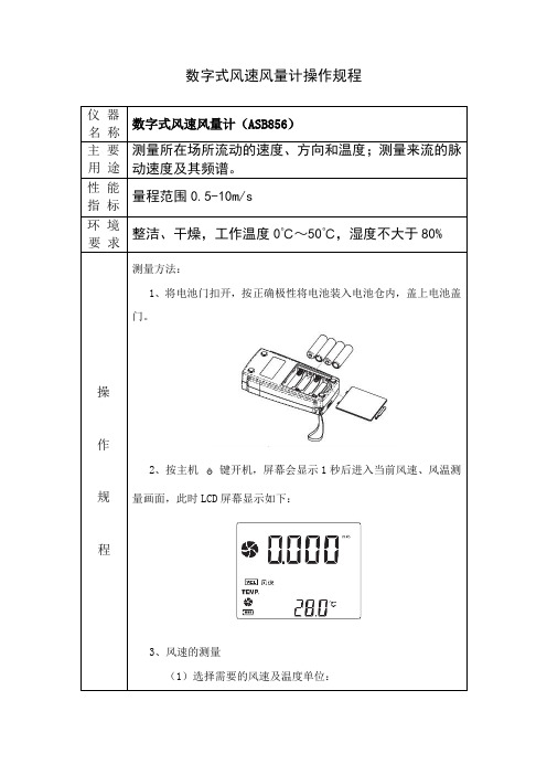
1、将电池门扣开,按正确极性将电池装入电池仓内,盖上电池盖门。
6、风量2/3V MAX值测量
(1)按“VEL/FLOW”键转到“FLOW”(风量测量)状态模式,此时LCD屏幕显示如图:
(2)按“UNIT”键设置好需要的单位。
(3)按“AREA”键。LCD下方4个数字会消失,此时则可输入风口面积,如1.2,再按“ENTER”键确定,再按“OPTION”键选择“2/3V MAX”此时屏幕显示如图:
(2)手持风速计,按风叶内箭头指示,将风叶对准出风口,保持风叶与风向垂直(注意:请勿用力挤压风叶,否则将导致风叶损坏或测量不准)。
4、风温和空气温度测量
(1)当测量风速时,风温同时会测量出来,小风叶图案会显示出来,并显示“TEMP”符号。
(2)选择“℃/℉”可按“℃/℉”键(数字键6)。
注意:
1)若当前为风量模式时(LCD左侧显示FLOW),此时可按“VEL/FLOW”键,反之亦然。
(4)将附机之风叶按正确风向对准出口即可测出风量的2/3V MAX值,再按“OPTION”键可退出风量2/3V MAX值的测量。
(5)2/3V MAX风量计算公式:FLOW=2/3×MAX风速×风口面积。
7、风量平均值测量
(1)按“VEL/FLOW”键转到“FLOW”(风量测量)状态模式,此时LCD屏幕显示如图:
LZCDCY04-14 testo 405-v1 热敏风速仪操作规程

龙州县疾病预防控制中心作业指导书版号:第三版文件编号:LZCDC/Y04-14Testo 405-V1热敏风速仪操作规程2012年12月28日批准 2013年1月1日实施龙州县疾病预防控制中心龙州县疾病预防控制中心发布编写、修订记录编写人:林葵娇完成编写日期:2012年12月10日审核人:黄建岩审核日期:2012年12月20日批准人:周培育批准发布日期:2012年12月28日版号:第三版修订次数及页码:第0次修订共4页Testo 405-v1热敏风速仪操作规程版号:第2010年版文件编号: LZCDC/Y04-14 1、目的为规范Testo 405-v1热敏风速仪的测定,特制定本指导书对其作必要的细化和补充。
2、适用范围适用室内、室外、公共场所环境中风速的检测。
3、职责检验人员:负责按照本检测方法对被检样品进行检测。
复核人员:负责对检测的规范操作以及检测结果是否准确进行复核。
科室负责人:负责对科室综合管理和检测报告的签发。
4、使用方法4.1 开机按一次ON键,液晶显示器会出现开机显示后出现当前读数。
4.2 转换显示参数反复按ON键,液晶显示器会按风速、温度、风量3数值界面变化。
4.3设定管道横截面开机状态下长按ON键,液晶屏幕第一个数值位置会闪动。
4.4.1反复按ON键改变数字直到需要的数字出现,停止2秒,数字将固定,开始设定第二位置。
4.4.2重复以上操作完成设定。
4.5关机长按ON 3秒,仪器关闭。
如果五分钟之内没有新的操作,仪器也会自动关闭5仪器维护与保养5.1电池更换如果测定测量器不能正常开机或屏幕不稳定,无法读取数值时,请更换电池。
更换电池方法:打开背面的电池盒,把旧电池取出,并放入3节新电池(AAA),注意电池极性,关上电池盒即可。
5.2仪器的使用和存放点姚避免剧烈震动、腐蚀性物质,温湿度超过仪器指标的环境。
5.3仪器设备使用记录(LZCDC/QBG )6 支持性文件Testo 405-v1热敏风速仪中英文使用说明书。
检测仪器操作说明
检测仪器操作说明维保检测仪器操作规程为了提高维保人员实际操作水平,全面提升维保工作,更好地服务于广大客户。
根据维保检测仪器功能、检测对象、国家标准等制定检测仪器操作规程。
一、设备名称:秒表名称:秒表量程:量程不小于15min;精度:0.1s应用范围:防火卷帘、消防电梯、火灾自动报警系统响应时间,应急灯及疏散指示时间,各消防设施联动时间等。
操作说明:1、检查仪器是否在检定有效期内。
2、使用前检查是否完好,开启关闭及各项功能正常。
3、每单项检测应重复两次,求平均值。
4、仪器使用后应置于干燥适宜的环境存放。
规范标准:*自动发电机组自动启动正常工作时间不应大于30s;*火灾自动报警系统响应时间不应大于30s;*湿式系统开启末端泄水装置5min内自动启动消防水泵;*干式系统开启末端试水装置1min内出水压力不应低于0.05MPa;*预作用系统火灾报警器确认火灾后2min,末端试水装置的出水压力不低于0.05MPa ;*泡沫系统做联动实验时从接到信号到喷射不宜(小于)1min;*气体灭火系统做模拟启动实验时应有20—30s延时;*应急照明灯工作时间不应小于20min,建筑高度超过100的建筑不应小于30min;*疏散指示标志应急工作时间不应小于30min;*消防电梯迫降时间不应大于60s。
二、设备名称:卷尺名称:卷尺量程:量程不小于30m;精度:1mm应用范围:测量室内、外消火栓间距、消防水带长度及设备设施高度、宽度等。
操作说明:1、检查仪器是否在检定有效期内。
外观完好、开启灵活。
2、在测量时需反复测量被测项目两次,求取平均值。
规范标准:1火灾探测器周围0.5m内不应有遮挡物。
2.手报距离地面1.3—1.5m。
3.从一个防火分区内任何一点到最近一个手报距离不大于 30m。
4.壁挂式火灾报警控制器底边距地面1.3—1.5m,靠近门轴一侧不小于0.5m,正面操作距离不小于1.5m。
5.柜式火灾报警控制器,当设备单列时正面操作距离不小于1.5m,双列时不小于2m,距墙维修距离不小于1.0m,其底高出地面0.1-0.2m。
数字气象仪使用说明书
XZC2-2D型数字气象仪使用说明书北京同德创业科技有限公司感谢您选择本产品!本产品依据中华人民共和国机械行业标准—JB/T9468-1999制造生产。
本产品已通过计量器具型式批准。
本产品关键部件为风速风向传感器。
在安装使用前请仔细阅读《使用说明书》并请妥善保存,以备日后查阅。
目录一、主要用途 (3)二、显著特点 (3)三、显示术语 (3)四、技术指标 (3)五、基本原理 (5)六、键盘功能 (6)七、操作方法 (7)八、故障判断 (10)九、维护保养 (11)十、安装程序 (11)十一、安装方法 (12)十二、贮存环境 (12)十三、保证期限 (12)十四、装箱清单 (13)十五、订货须知 (13)十六、附图说明一、主要用途本仪器主要用于各种类型的舰船、海洋石油钻井平台以及海洋口岸气象台站,通过有线遥测迅速提供准确的气象数据:1.瞬时合成风速与瞬时合成风向。
2.2分钟平均合成风速与2分钟平均合成风向。
3.瞬时真风速与真风向。
4.2分钟平均真风速与2分钟平均真风向。
5.空气温度与空气相对湿度。
6.大气气压。
二、显著特点1.先进的计算机技术与传感器技术,仪器的可靠性大为提高。
2.大屏汉字显示可同时显示多项测量数据。
3.全中文菜单。
人机对话功能屏幕显示,使用更直观。
方便的健盘操作方式,可人工输入舰船的航速、航向。
4.参数单元采用320×240点阵液晶显示,即使在夜间或灯火管制的情况下,也能清晰地显示测量数据。
5.通过了“军检”和“船检”,显示出仪器的高质量。
6.独特的声、光大风报警功能,其报警风速值可根据用户要求任意预置。
7.仪器配有微型打印机,用户可根据需要把测量数据自动或手动打印存档。
其打印时间可根据用户要求任意预置。
8.仪器配有外接[GPS].卫星定位系统接口;用户可根据[GPS]协议提供数据预置。
9.仪器配有气压接口,可根据需要对实地进行测量。
10.数据存储功能,仪器配有大容量的存储器,可实时的存储、打印。
数字风速计使用说明书-HoldPeak

例如:
(1) 测量风速最大值时,LCD 屏幕上方显示“MAX”字
样,如图 4:
图4 (2) 测量风速最小值时,LCD 屏幕上方显示“MIN”字
样,如图 5:
2. 操作说明
-2-
图5
(3) 测量风速平均值时,LCD 屏幕上方显示“AVG”字 样,如图 6:
图6
数据的保持、存储、读取及清除 数据保持:
保养和保修 1). 保养: 电池的更换和产品的保养
a 当您长时间不使用本机时,请将电池仓内电池取 出,以免电池漏液后腐蚀电池盒及电池极片。
b 开机后,LCD 上显示 " " 符号时,请您及时更 换电池,打开电池门,取出旧电池,换上新的 9V 电池(注意电池极性),然后扣合电池门。
机壳清洗 不能使用酒精、稀释液等清洗机壳,会对 LCD 屏幕 有腐蚀作用,所以清洗机壳只需用少量清水轻轻擦拭 即可。
Scale
Resolution Accuracy
℃
0.0-45.0
0.1
±1.0℃
℉
32.0-113.0
0.1
±1.8℉
5 .工作环境:
温度
湿度
主机 风速传感器
0-50℃(32-122℉) 0-60℃(32-140℉)
≤80%RH
6. 储存环境:
温度
-10-60℃(14-140℉)
湿度
≤80%RH
7. 电源: 6F22 9V×1
:大风叶符号,表示测量风速,风量状态并
且测量时会随风速,风量转动。
:风速值和风量值显示区域
:平均值测量
、
: 最小、最大值显示
:读取记录数据时此符号显示
: 数据保持符号
日本加野A531智能风速仪说明书

智能型环境测试仪A531一操作面板按键说明MENU 主菜单START/HOLD 开始/停止切换SET 选定确定键MODE 每项测试功能切换上下三角键光标移动以及数值选择二仪器的主菜单1NORMAL 通常测试方式2DUCT TYPE 通道的类型选择3CALCULATION 演算测定方式4FLOW RATE 风量测量方式5DATA OUTPUT 数据的输出6DATA CLEAR 数据的删除7UTILITY 时间测定单位的测定8压力零点的调整通常只有在测压力的时候才有三主菜单MENU说明主菜单下有8个子菜单分述如下NORMAL 通常测试方式进行正常的风速测定不需要任何参数设定DUCT TYPE 通道的类型选择其下面有6个子项ENTRY NO 可保存1~25种形状的风道尺寸SHAPE通道类型的选择RECTANGLE 方型CIRCLE 圆形W SIZE 宽 1-999H SIZE 长 1-999以上是选择方型如果选择圆形则只有一项参数即圆直径的选择UNIT mm/inch单位的选择毫米/英寸SA VE INFO 保存信息CALCULATION 演算测定方式R1420/1500R1420/1500的意思是仪器共能够存储1500个数据现有1420个剩余MODE 测量方式A VERAGE 平均测试方式INSTANT 立即测试方式SAMPLING TIME 采样时间间隔 1-999NO TRIAL N测定次数 1-999DATA STORAGE 测定数据是否保存 YES/NOSET TO START 返回测试画面FLOW RATE R1500/1500风量测定方式SAMPLING TIME 采样时间间隔 1-999NO TRIAL N测定次数 1-999MEAS POINT 在指定时间内读取的数据次数 1-999如果为30次10秒即为在10秒钟内读了30次数30次的平均数反映到屏幕上DATA STORAGE YES/NO数据是否保存DUCT ENTRY NO 返回到通道类型测定菜单SET TO START 返回测试画面DATA OUTPUT 数据输出DISPLAY 显示测试结果PAGE页数输出页的号MODE模式CALCULATION A A VERAGE平均IINSTANT立即DATE日期年/月/日TIME时间小时/分钟/秒DATA/DIV测试的总数SHAPE形状R方型/C圆形只有在风量测试时才有这个选项PRINTER 打印各项参数同5DATA CLEAR 数据删除CLEAR 删除单个数据START 开始END 结束SET YES/NO例如START 1END 4SET 选择YES 则从第一个到第四个都删除了ALL CLEAR 数据全部删除UTILITY 参数设定TIME ADJUST 时间调整DATE 日期年/月/日TIME 时间小时/分钟/秒SA VE INFO 保存信息UNIT ADJUST 单位设定VELOCITY 风速m/s米/秒或FPM每分钟英尺TEMPERATURE 温度或℉FLOW RATE 风量m3/min m3/h ft3/h ft3/minBAUD RATE 波特率 9600/4800/19200/38400 必须设置为9600 SA VE INFO 保存信息ANALOG OUTPUT 各种项目测试范围的选择OUTPUT SELECT 输出选择VEL风速HUM湿度TMP温度单位范围TEMPERATURE 风温 0-50-10-400-100VELOCITY 风速0-5m/s0-10m/s0-30m/sHUMIDITY 湿度0-50%RH0-100%RHSA VE INFO 保存信息TC T H SETTC T H SET YES/NO存储设定YES 风速风量温度压力风温同时显示NO 风速风量显示SA VE INFO 保存信息压力零点调整四注意事项进入NORMAL后屏幕显示TC 1每1秒的输出值TC5每5秒的输出值TC10每10秒的输出值全部测试完后屏幕显示DT 露点温度11.4在这个温度会有雾出现DI 不快指数 66.7 人在这个指数下会感到不舒服不快指数相对应的值在说明书中可以查到ProbeA‚T P A‚T S P l n c d k A‚T SAir Velocity SensorTemp. CompensationSensorHumidity SensorTemperature SensorWind Direction MarkProbe Number Unit• mmi MODELA531only•Temp. CompensationSensorTemperature SensorAir Velocity Sensor Probe Numberl n c d k A‚T l n c d k A‚T SAir Velocity SensorTemp. CompensationSensorHumidity SensorTemperature Sensor Probe NumberAir Velocity SensorTemp. Compensation Sensor Temperature SensorProbe NumberMulti-Function Thermal AnemometerCAT.NO.EA5SE-0EEVentilation Testing Laboratory Control Cleanrooms IAQ Investigation Industrial HygieneQuality ControlA531-01A541-01A542-01A533-01A543-01Climomaster SeriesFeatures:•Probe Compatibility feature allows you to havespare probe .•The world’s most accurate handheld hot-wireanemometer in its class.•Robust design.•Detachable probe.•Automatic Flow Rate Calculation function .•RS232C terminal for data logging.•Stores up to 1500 measurement data.•Differential Pressure available as an option.Benefits:•Probe Compatibility saves your downtime andshipping cost.•With ±2% accuracy, there is no match!•If you have more than one unit, detachable probeallows you to share the main unit or the probe.•By registering duct sizes (up to 25 duct sizes), itautomatically gives you flow rate.•Well designed software allows you to reach thedata instantly.•You can store the data or you can dump it to yourPC via RS232C cable and software (both optional).•A variety of optional parts available.A531A541A542A533A543A 531-01A 541-01A 542-01A 533-01A 543-01RangeAccuracyResponse TimeApprox. 4sec.*ResolutionRangeAccuracyResponse TimeResolutionRange2.0 to 98.0%RH 2.0 to 98.0%RH --Accuracy +/-2.0%RH from 2to 80%RH+/-3%RH from 80to 98%RH+/-2.0%RH from 2to 80%RH +/-3%RH from 80to 98%RH --Response Time Approx. 15sec.Approx. 15sec.--Resolution0.1%RH 0.1%RH --Range Accuracy Response Time Resolution Digital Analog Main Unit Probe 41-104 F (5 to 40C)Storing EnvironmentOptional Accessories Spare Probe, Analog Output, Pressure Sensor, Extension Rod, Printer, Printer Cable, CommunicationCable, Software (for Windows), AC Adapter: AC100-240V 50/60HzWeightApprox. 0.9lbs (400g)Standard KitCarrying Case, Operation Manual, AA Batteries, Probe Cable Battery LifeApprox. 10hrs. Continuous at 984fpm (5m/s), 68F (20C) with alikaline batteries OperatingEnvironement41 to 104F (5 to 40C)32 to 140F (0 to 60C)OutputRS-232c (Baud Rate 4800, 9600, 19200 and 39400bps)DC0-1V (Select from Air Velocity, Air Temperature, Relative Humidity and Pressure)Power Supply6 x 1.5V AA Batteries, AC Adapter (Optional): AC100-240V DifferentialPressure(Optional)-5.00 to +5.00kPa +/-(3% of reading +0.01)kPa Approx. 1sec.0.01kPa Relative Humidity --------1fpm (0.01m/s)Air Temperature 32.0 to 140.0F (0.0 to 60.0C)+/-1F (+/-0.5C)Approx. 30 sec.*0.1F (0.1C)10 to 984fpm (0.05 to 5.00m/s)+/-2% of reading or +/-3fpm (+/-0.015m/s) whichever is greater Approx. 1sec.*Approx. 7sec.*ModelStandar d P robeAir Velocity 20 to 6,000fpm (0.10 to 30.0m/s) 1fpm 0.01m/s from 0 to 9.99m/s 0.1m/s from 10.0 to 30.0m/s Model Standard Probe Spare Probe Measuring Range Probe Type Directivity Velocity &Temperature Relative Humidity A531A531-01A531-0120 - 6,000 fpm Rod Mono ○○A541A541-01A541-0120 - 6,000 fpm Rod Mono ○×A542A542-01A542-0120 - 6,000 fpm Needle Omni ○×A533A533-01A533-0110 - 1,000 fpm Spherical Omni ○○A543A543-01A543-0110 - 1,000 fpm Spherical Omni ○×SpecificationsSelection GuideKanomax reserves the right to change specifications and accessories without notice.ATTENTION !For safe and trouble-free operation, please read “Operation Manual”carefully before use of the instrument.Kanomax USA, Inc. 250 West 57th Street, Suite 816New York, N.Y. 10107 U.S.A.Phone: 212-489-3755 Fax: 212-489-4104 E-mail: kanomax@Web site: Kanomax Japan, Inc. 2-1 Shimizu, Suita, Osaka, 565-0805 Japan Phone: +81-6-6877-0183 Fax: +81-6-6879-2080 E-mail: sales@kanomax.co.jp Web site: www.kanomax.co.jp。
XK3110-A说明书2010版

目录
一、概述 (1)
1 型号定义与功能简介 (1)
2 主要功能 (1)
3 工作原理 (2)
二、技术规格 (3)
1 一般规格 (3)
2 模拟测量部分 (3)
3 开关量输入部分 (3)
4 开关量输出部分 (3)
三、仪表前面板说明 (4)
1 外观 (4)
2 显示窗口1 (4)
3 显示窗口2 (4)
4 按键 (5)
四、仪表后面板说明 (6)
1 说明 (6)
2 电源插座 (6)
3 开关量输出插座 (6)
4 开关量输入插座 (7)
5 传感器插座 (9)
6 打印/通讯插座(选配) (9)
五、仪表配置设定 (10)
1 有关术语 (10)
2 基本操作 (10)
六、仪表通讯设定(选配) (15)
七、仪表打印设定(选配) (16)
八、仪表校称操作 (17)
九、仪表配方设定 (20)
十、仪表落差设定 (22)
十一、仪表的具体应用 (24)
1 仪表生产控制流程图 (24)
2 生产前调试操作建议 (25)
3 生产操作步骤 (25)
4 线控按钮盒控制卸料时的注意事项 (27)
5 爬斗行程开关控制卸料时的注意事项 (27)
十二、常见故障处理 (28)
十三、仪表尺寸 (31)
十四、附件 (32)
十五、快速应用 (33)。
- 1、下载文档前请自行甄别文档内容的完整性,平台不提供额外的编辑、内容补充、找答案等附加服务。
- 2、"仅部分预览"的文档,不可在线预览部分如存在完整性等问题,可反馈申请退款(可完整预览的文档不适用该条件!)。
- 3、如文档侵犯您的权益,请联系客服反馈,我们会尽快为您处理(人工客服工作时间:9:00-18:30)。
C C Y Y--22001100A A数数字字风风速速仪仪说说明明书书
一.概述
1.用途
CY-2010A数字风速仪是用于测量风速的袖珍型测量仪,该仪器广泛用于环保、劳动卫生、体育、科研、公共场所及农业等方面的采暖通风、室内环境、超净间、设置在风洞内的模型试验、管道内的风速压力测试、空调检修及能力试验、地铁隧道的通风检测、工厂生产监测、建筑劳动作业现场环境卫生管理、空气调节等。
该仪器小巧,便于室内及室外使用。
2.简介
CY-2010A数字风速仪是一种热球式风速仪,本仪器由探头和电路二部分组成,探头经过导线连接到主板上,测量时将探头直接暴露在空气中,气流的变化而影响到探头阻止的变化,从而使主板的电流发生变化,经过增益和逻辑处理后,显示为当前的风速值,由液晶直接显示出来。
该仪器采用集成电路设计,具有灵敏度高、体积小、重量轻、操作简单、数字直读等优点。
该仪器采用交直流两用供电方式,直流采用500mA,12.6V锂离子充电电池,交流是用专用充电器直接给仪器供电,因此方便可靠。
二.工作原理
CY-2010A数字风速仪是探头阻值变化而产生不同的电流的原理制成的。
灵敏度极高的探头在遇到不同风速时使其冷却程度不同,阻值变化不同,从而产生的电流也不同,将电流信号转化为电压信号,经过主板进行放大,经增益调整、逻辑信号分离、线性化校正,将非线性信号转换成线性信号并由面板上的液晶显示器直接显示出风速的数值。
三.仪器的结构及功能介绍
(一)结构图
(二)功能介绍
1 .液晶屏幕
2 . POWER电源开关按键
3 . HOLD保持按键
4 . 机壳
5 . 充电器插口
6 . 电缆线
7 . 拉杆
四.技术参数
1 . 测量范围:A型0—10m/s B型0—30m/s
2 . 分辨率:0.01m/s
3 . 精确度:±(读数×2%+0.2)m/s
4 . 4位字段液晶显示
5 . 工作环境:5℃—50℃清洁空气中的风
6 . 电源:①锂离子充电电池
②AC适配器(选择性)
7 . 规格:主体:135×70×30mm
探头:160mm—422mm可拉伸探杆
电缆:75mm可拉伸弹簧电缆线
8 . 重量:0.28Kg
五.操作说明
1 . 开机检测,按POWER键仪器加电,几秒钟后仪器显示回到“0.00”,
这时已经进入测试状态,待仪器充分稳定后开始测试。
2 . 将仪器拿到测试地点,拉开拉杆,漏出传感器探头,使传感器朝向风
速方向,待液晶显示较为稳定,所显示的数值即为所测得风速。
此时
按下“HOLD”键,液晶保持闪烁显示所测得数值,再按下”HOLD”
键又回到测试状态。
可多次测量取其平均值。
(注意:人的呼吸远离拉杆中的传感器探头)
六.保养维护
根据检测频率的不同,每隔一段时间要对仪器进行一次保养。
仪器使用完毕必须关闭电源,当仪器长时间不用时,为了保护充电电池和程序稳定,每隔三个月要进行充电一次,并且不要放在腐蚀性气体过高的环境中。
请注意不要轻易打开仪器内部,如需进行较大维修,请寄回我公司由专业人员进行修理。
七.常见故障
八.附件
1. CY-2010A主机: 1台
2. 专用充电器: 1个
3. 说明书: 1份
4. 保修卡、合格证:各1份
九.售后服务
1.凡购买本公司CY-2010A产品,自购机之日起保修三年(电池保修1年)。
保修期内如果有问题,本公司将负责免费维修及更换部件,保修期外只收
取成本费,努力为用户服务是本公司的行为准则。
2.下列情况所出现的故障不在免费保修范围内
⑴因用户操作使用和保管不当引起的故障。
⑵因非专业人员修理和改造而引起的故障。
⑶因未经与本公司协商而在特殊场合使用引起的故障。
⑷因火灾、水灾、震灾等不可抗拒原因而引起的故障。
⑸因储存环境恶劣,而对仪器造成的损坏,(如酸性或碱性过大而对仪器
造成了腐蚀的)。
十.风速等级表。