戴森V6说明书中文版本
SCHLAGEL, INC. EDI-V6控制器使用指南说明书
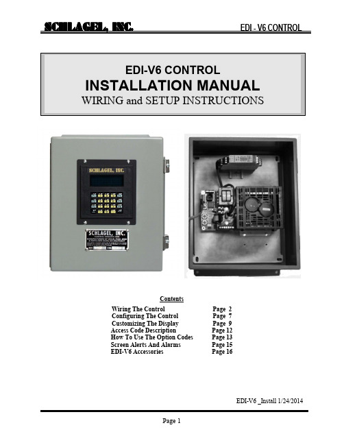
ContentsWiring The Control Page 2 Configuring The Control Page 7 Customizing The Display Page 9 Access Code Description Page 12 How To Use The Option Codes Page 13 Screen Alerts And Alarms Page 15 EDI-V6 Accessories Page 16EDI-V6 _Install 1/24/2014Figure 1 General wiring layout of the power modulewiring instructions in this document could leadThe patented EDI-V6 control is furnished with an inverter drive, therefore a mechanical reversing starter is no longer used. Since the inverter can stop the motor in a pre-determined time, regardless of load, it also eliminates the need for a brake motor. The installation is further simplified by using a 120-volt supply to power both the control and the inverter. The inverter converts the single phase supply to 240-Volt 3 Phase power needed by the motor.Caution: The inverter drive has been factory adjusted to function properly with any EDI distributor. Changes to the inverter adjustments will alter the positioning of the distributor spout.Figure 2 High voltage wiring terminations.High Voltage Power WiringHigh Voltage Wiring. Refer to Figures 1 and 2The 120 Volt supply (L1 and L2) may come from a fused disconnect or a panel mounted circuit breaker rated for 10 Amps. The ground wire is attached to one of the two ground terminals.The 1/2 HP 3 phase distributor motor must be wired for 240 voltsThe motor power wiring carries 0-240 VAC 3 Ph, 2.4 Ampconnected to the terminals marked T1, T2 and T3. The ground wire is attached to the open green ground terminal. It is not necessary to considerThe control will determine and correct the rotation during thedescribed later in this manual.L1,L2120 VAC, 9.6Amp InputGroundsT1,T2,T3240 VAC 2.4AMP OutputThe sensors are part of an intrinsically safe (IS) circuit created by the barrier relay. There are 2, two wire sensors located on the distributor. These are Intrinsically Safe (IS) sensors suitable for many hazardous locations including Class II, Division 1, Group G. When properly guarded from non-IS wiring they can be run openly through these locations. These 4 wires can be of almost any wire type, 26 ga. or heavier, up to 1000' in length. IS rules do not allow them to be run these wires in conduits or cable trays with other power circuits. Route and mark these wires according to jurisdictional authority IS code.Figure 3. Turk IM1-22EX-T Barrier RelayIdentifying sensors at the distributor.Sensor 1 is the one closest to the distributor pivot point and reads the inside of the code cluster.Sensor 2 is the farthest sensor from the spout pivot and reads the outside of the code cluster.SensorIntrinsically Safe WiringSensor 1 Brn/Blu Brn/BluLEDSensor 1 LED switches upPower LEDConfirming that the motor, barrier relay and sensors are properly connected is done at the power module using the pushbuttons on the CB6 board shown in Figure 4. These buttons have alternate uses when the distributor is in operation and will be explained later in this manual.Figure 4 Manual motor buttons on EDI-CB6 board.Apply 120 power to the power module. Refer to Figure 4 and check the following on the CB6 board:The 2 power LEDs should be green.The 2 digit display should show ‘ 0’.Next Refer to Figure 3 and check the following at the barrier relay:The switches are set properly.The power LED should be green.The sensor LEDs can be Yellow or Off but not Red.Now, pressing the MTR1 or MTR 2 buttons will activate the motor on the distributor in either direction. While the distributor spout is moving, verify that both the sensor 1 and 2 LEDS are blinking.Note: The ‘IM1’ barrier relay has 2 lamps marked 1 & 2. These are shown in Figure 3. If either of these lamps are red, it is an alarm indicating either an open circuit or short circuit in the wiring of the corresponding sensor or improper setting of the barrier relay switches. Correct before proceeding.Lamps 1 & 2 indicate the switched status of the 2 sensors and will turn on and off as each code cluster on the distributor codewheel passes the sensors.See the Figure 1 for the location of the pushbutton switches that manually operate the motor. Manually press the Fwd or Rev buttons to begin spout motion. If you are installing a Flatback or Swingset distributor, the spout may be against one end or the other so there may be no motion unless the other side of the starter is engaged.The Lamp 2 on the relay should blink off rapidly in sets of 5 blinks per burst. The Lamp 1 on the relay should blink off intermittently during each burst.If either one or both sensors do not blink or the blink pattern is on the wrong lamp, the wiring must be corrected before proceeding further with the installation. Correct the wiring or barrier relay switch status and repeat the blink test.This completes the wiring of the EDI Control.The control must now configure itself to operate the distributor it is wired to. This procedure is covered in the next section of the manual.Note: If the install prompt shown does not appear on the screen, you may still proceed with installation by pressing the number ‘1’ instead of ‘Enter’. The EDI-V6 control uses an automated setup routine to recognize the distributor and configure the control. This is done once, only when installing the control. The control must be wired and the sensors connected properly as described earlier in this manual. This setup will fail if those instructions are not followed first. Note: Some of the information on the sample screens shown may be different than your screen depending on the type of the distributor being installed.Upon Power-up or Reset, the control will display the following screen: To begin the automated setup from the above screen, press ‘Enter’The screen will now display the above information as the automated setup progresses. This process may take a few minutes depending on the style and size of the distributor. The control will determine the type of distributor, code pattern, number of ducts and determine and adjust the motor direction if necessary.Without user intervention the control begins the Autotune sequence. This attempts to find, and self adjust, the spout to the best duct centering adjustment.Starting the Setup RoutineUpon completion of the Autotune process an information screen will appear with the information it has acquired. Be sure to confirm that these details are correct.Press ‘Enter’ after confirming this data.Press ‘Enter’ to finish the setup and begin normal operation.This is the OPERATING Screen. All operator control begins with this screen.Customization of captions, spout access numbers, destination names and many other options may now be made. Information on how to do this can be found in the next section of this manual.During the initial installation, default information is set so that the distributor can be operated without further changes. However, most operators would like familiar names and access codes assigned to each position of the distributor. The EDI-V6 control allows customization of Line1 and Line 3 using the control keypad to make the changes.Line 3Line 4In the examples above, the default O PERATING screen is shown on the left and afully modified display on the right. These changes are made using special 4-digit access codes. The following changes were made to the default O PERATING screen: Line 1 The caption on this line has been changed from “SCHLAGEL, INC .” to “RECEIVING LEG ”.Line 2 This line is used for system alerts and information and cannot be modified. Line 3 the access code <001> has been changed to <031>. This allows the operator to move the distributor spout to this position by entering 31, a more logical choice for accessing this position. Also, the name for the destination has been changed from “POSITION 1” to the more logical “BIN 31”.Each distributor position can be individually programmed and displayed on this line.Line 4 This line is used for system status and keypad input and cannot be modified.Changing the Line 1 caption is a good example of using the special access codes and character programming so we will explain all of the details here.At the O PERATING screen press 8004 Enter . That is the access code for changing the caption. The blinking cursor shows where each character will be entered. Pressing any numeric key will enter that number and move the cursor right to the next position.The Shift key is used to enter an alpha character. Consider the number 7 key. On the top left of the key is the character A and at the top right is the character B. To enter an A press the Shift key once and a ‘-‘ will appear under the cursor. Now press the 7 key and the A character will be entered. If the Shift had been pressed twice, a “=” would have been shown and after pressing the 7 key, a B would have been entered. Pressing the Shift key multiple times changes the cursor background between “ “, “-“, “=”, and back to “ “.Up to 16 characters may be entered. A space is entered with a single Shift and Space. A backspace can be executed by a double Shift and Space . When finished, press the Enter key. The display will return to the O PERATING screen showing the new caption. Changing the caption is a good way to build your editing skills without affecting the operation of the distributor.Note: To modify duct information, the spout must first be set to the position you intend to modify.At the O PERATING screen press 5993 Enter . This displays the first prompt screen (see below) requesting the access number. This can be any number, 1 thru 255, and will be the number used to move the spout to this duct from the O PERATING screen. After entering the access number press Enter .The next prompt screen asks for the F-KEY number. There are 6 ‘speed-dial’ keyson the keypad that can be used for frequently accessed positions. Here is where you can specify the assignment of a function key for this position by entering a number, 1 thru 6. Enter a 0 (zero) if no function key will be assigned to this position. When finished, press Enter . Modify Line 1 (Access code 8004)Modify Line 3 (Access code 5993)The last screen allows the assignment of a logical name for this duct. Use the same procedure as explained above for editing the caption. Up to 14 characters may be entered. When finished, press the Enter key. The display will return to the O PERATING screen showing the new information.Hint: The position of the distributor can always be moved to the desired position, regardless of which access number was programmed, by pressing the Minus key and then the ‘absolute’ position required. The ‘absolute’ position is the physical number of the duct, 1 through the total number of ducts on the distributor.two access codes have been explained previously, 8004 and 5993. Using these codes allowed changes to the configuration and operation of the EDI-V6 control. There are other access codes used to change the operation of the distributor. Most of these must be used with caution because they can adversely affect reliable operation of the distributor.Below is a list of access codes and a brief description of each. These are available to the user that is familiar with the use of these codes. Please contact our technical support group if you are unsure of any modification you wish to make.Note: The following codes are for controls with firmware revision EDI-V6.100.5 or earlier. It is possible that some may be elimitated or changed in future revisions. AccessCodeName Description5991 New Configure the EDI Control to a new distributor.5992 Global SpoutAdjustment Manually input the stop position adjustment numbers for any duct. This number will then be used for all spout positions.5993 Define DuctData Assign Access numbers, Function numbers and Names for any duct.5994 EraseMemory Erase all duct names, numbers and definitions and replace them with default information.5995 Display EDIData Displays 3 screens of critical setup and operation information.5996 Set Options Used to set various modes of operation andcommunication. See the 'Options' table for details.5997 IndividualSpoutAdjustment Manually input the stop position adjustment numbers for the current spout position. This number will then be used for this spout to duct position only.8002 Auto Mode Starts operation of the distributor in a random mode.Distributor then runs continuously until any key ispressed.8003 ResetCountersZeros all Access, Alarm and Position Error counters. 8004 Edit Caption Change the Line 1 distributor name.8005 Edit Net Addr Allows a change to a network address letter.9001 Auto TuneFullAuto tune every spout to duct position in the distributor9002 Auto TuneLimited Auto tune only one spout position in the distributor and use this number for all positions.Some accessories and operating functions of the EDI-V6 control require software switches to be turned on or off. These switches are called Options and are made accessible by the special access code 5996.Note: Changing options from factory defaults may have unexpected consequences. Most of these must be used with caution because they can adversely affect reliable operation of the distributor. Please contact our technical support group if you are unsure of how to use these options.See the chart on the following page for a complete list of options.To change an option, press 5996 Enter at the operating screen. The following example screen will appear.The Ones and Zeros on Line 2 signify which of 16 option switches are on and which are off. Starting from the left, Options 1-3 are on, 4-11 are off, 12 is on and 13-16 are off. Refer to the EDI-V6 OPTIONS chart on the next page to determine the action for each switch.Turning The Network Option On And OffThe most common option change made in the field is turning the network on and off. For that reason we will use it in the following example.The table on the next page shows that option 7 turns the network on or off. In the screen above it is shown as being off. To turn it on, press 7 Enter. The following screen then appears showing the present status of this option and requests a 0 or 1 input to change it, or just press Enter to leave it unchanged.Press 1 (for on).In the special case of turning the network on, you will be immediately asked for a network address. In this case you must enter A through R , T or U using the alpha input described earlier before the next screen appears.The first screen will re-appear, showing the change and awaiting the selection of another option. Pressing Enter without entering a number will return the control to the O PERATING screen.Note: The following codes are for controls with firmware revision EDI-V6.100.5 or earlier. It is possible that some may be elimitated or changed in future revisions.EDI-V6 OPTIONSOption Name Range Default1 Boot Prompt 0=Base, 1=Alternate 12 In Position check 0=Off, 1=On 13 Position Alarm 0=Off, 1=On (a) 14 N/A 05 N/A 06 N/A 07 I/O Network (d) 0=Off, 1=On (b) 08 N/A 09 Auto Mode Speed 0=1 Sec, 1=4 Sec 010 Slow Speed 0=Off, 1=On 011 Simulator Mode 0=Off, 1=On 012 10 Second Timeout 0=Off (5 Sec.), 1= On 113 N/A 014 N/A 015 N/A 016 N/A 0 Notes(a) Special relay option hardware must be added.(b) Only one of Options 5, 6 or 7 can be on at any time. Otherswill be automatically turned off.(c) Must be off when using the UIO interface.(d) Must be off when using the UIO interface in Digital mode.Must be on when using the UIO interface in Network mode.The EDI-V6 control continuously monitors the distributor for abnormal behavior and will notify the operator when a detectable error occurs. The notification is displayed on Line 2 of the display. Various interfaces are available to activate audible or visual alarms, or to notify PLCs or other computer equipment of the error. Please contact us if you are interested in any of these accessories.Reason: The control has attempted to move the spout but has not received any feedback that it is moving. If it does not receive feedback for 10 seconds, the control will turn off the motor and display this error message.Cause: The spout is jammed, the clutch is slipping or the sensor circuit is not functioning.Remedy: This is a fatal error. Press Enter and the control will return to the RESET screen. This is almost always a mechanical obstruction at the distributor.Reason: When the control was positioning the spout over a duct, it was not able to set it to the exact predetermined position.Cause: The spout adjustment number may be off or there is some mechanical difficulty preventing proper final positioning.Remedy: This is not a fatal error but the alarm will stay in the screen until a successful position has been achieved. To clear the alarm, re-enter the access number so the spout can reset itself to the correct position.Reason: This error message indicates that the spout has been moved out of position after a successful stop. EDI-V6 controls continuously monitor spout position and raise this alarm if the spout moves out of position.Cause: Something has electrically or mechanically disturbed the spout position over the duct.Remedy: This is a fatal error. Press Enter and the control will return to the RESET screen. Check for a loose clutch or loose drive chains in the drive assembly.Reason: While the control is moving the spout it continuously anticipates the next code it will encounter. If the next code does not match the anticipated code, the control will attempt to re-read it up to 3 times. If it fails on the 3rd try, the control will issue this error.Cause: An improperly positioned sensor block in the distributor usually causes this error.Remedy: This is a fatal error. Press Enter and the control will return to the RESET screen. Position and shim the sensor block properly. Clean the surface of the codewheel.TIMEOUTPOSITIONING ERRORSPOUT MOVEDSENSOR ERRORUIO Serial or Ethernet Interface ModuleThe UIO is a multi-function interface to the EDI control. It can act as a digital I/O device or a network scanner to combine multiple EDI controls and communicate with a PLC via protocols such as Ethernet/IP, Modbus-RTU, Modbus/TCP and DF1. It can also directly operate motor starters, push buttons, lamps and alarms. This DIN rail mounted module can be placed up to 4000’ from the nearest EDI control, next to a PLC or MCC.Remote Keypad/Display KitRemote keypad/displays allow operation of an EDI control from multiple locations. The display can be furnished loose or installed in a 8 x 10 x 5 NEMA 12 cabinet.Alarm RelaySeveral relay options are available to indicate when a error occurs or to confirm that the distributor is in the indicated position. In addition to the relay, these accessories can include audible or lamp indicators.Please contact us if you need custom enclosures for multiple EDI controls, UL/CSA labeling, special interfaces or other options that are necessary to meet specific site requirements.Schlagel, Inc.491 N. Emerson, Cambridge MN 55008763-689-5991, 800-328-8002 Fax 763-689-5310 ******************,。
MRAS6中文操作手册
V 1.0目录操作须知 (3)仪器介绍 (4)安全通则 (5)密闭微波消解中不适消解的物质 (6)高温下化学物质的安全要点 (6)安装 (7)工具 (7)安装地点 (7)开箱 (8)检查 (8)仪器描述 (9)软件图标和按键指引 (13)创建传统方法 (14)编辑方法 (19)删除方法 (20)运行方法 (21)系统菜单 (25)工具 (25)系统 (25)诊断 (26)功率 (26)红外 (26)压力 (27)升级管理 (27)设置 (28)维护、故障解决及服务 (37)清洁 (37)微波泄漏测试 (37)微波功率测试 (37)温度标定(红外传感器) (40)红外温度传感器的校验 (42)压力标定 (43)升级固件 (43)故障解决指南 (44)规格 (47)保修 (48)操作须知MARS6仪器所使用电源必须具有良好接地,以防电源短路对仪器造成严重伤害。
仪器配备了接地插头,必须插入正常接地的插座中。
如果接地要求不能达到或者怀疑仪器没有正常接地,请咨询电工或者相关认证部门。
如果需要使用延长线,仅适用3插头延长线,并保证插入3插头接地插座。
延长线的标号必须等于或者高于仪器原装线指标。
仪器不应该放置在易受电磁干扰的设备旁边。
仪器应远离磁场,微波泄漏量应小于5 mW/cm 2。
本仪器如果选配有磁力搅拌功能会产生一定的磁场,患有心脏病或体内有心脏起搏器的人员请勿操作使用仪器。
仪器发生问题时,维修应由CEM 公司专业工作人员来完成。
本仪器所通过美国、加拿大、欧共体相关安全标准。
本手册中使用的Teflon 为E.I. DuPont 公司注册商标。
仪器介绍微波加速反应系统(MARS6)是一种应用于消解、萃取、蛋白水解浓缩、干燥、合成等实验室工作的仪器。
它的主要功能是为AA(原子吸收)、ICP(电感耦合等离子发射光谱)和LC(液相色谱)等分析的前处理加速样品反应,缩短处理时间,从而提高工作效率。
MARS 组成:◆磁控管(输出功率:0~1800W±15%,IEC)◆防腐内腔◆排风扇及排气管◆数字化电脑编程,每个程序最高可达5步◆自动转盘◆三个内锁开关和一个检测开关保护仪器在开门时停止微波发射MARS 使用微波能量加热样品。
戴森吸尘器说明书
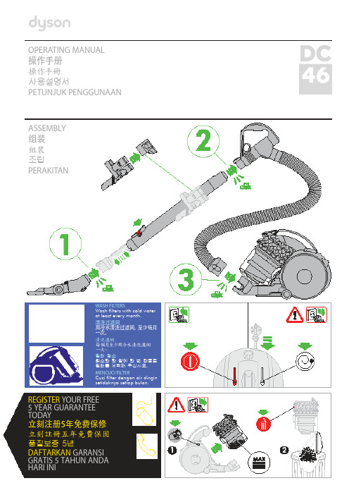
OPERATING MANUAL操作手册操作手冊사용설명서PETUNJUK PENGGUNAANASSEMBLY组装組裝조립PERAKITANWASH FILTERS清洗过滤网清洗濾網필터 청소MENCUCI FILTERREGISTER YOUR FREE5 YEAR GUARANTEE TODAY立刻注册5年免费保修立刻註冊五年免費保固품질보증 5년DAFTARKAN GARANSI GRATIS 5 TAHUN ANDA HARI INIDYSON CUSTOMER CARETHANK YOU FOR CHOOSING TO BUY A DYSON APPLIANCEAfter registering your free 5 year guarantee, your Dyson appliance will be covered for parts and labour for5 years from the date of purchase, subject to the terms of the guarantee.If you have any questions about your Dyson appliance, call the Dyson Helpline with your serial number and details of where/when you bought the appliance.Most questions can be solved over the phone by one of our trained Dyson Helpline staff.Alternatively visit for online help, general tips and useful information about Dyson.戴森客户服务感谢您选择购买戴森产品登记获取 5 年免费保修后,您的戴森产品自购买之日起,将享受 5 年的零件和人工保修服务,但须符合保修条款的规定。
Bridgelux V6 HD LED Array 产品数据手册说明书
Gen. 7V6 HD LED Array Product Data Sheet DS401V Series™ HD LED array product, an ultra-high lumen density COB product line, is designed for high intensity spotlights used in commercial and retail settings. V Series HD arrays offer industry leading color over angle uniformity, and replace ceramic metal halide lamps by providing equal or greater center beam candle power at lower power and at greater lifetimes. Their tight beam control and exceptional quality of light is well suited for demanding directional spot applications.The V6 HD LED array is available in a variety of CCT and CRI combinations providing substantial design flexibility and energy efficiencies.Lighting system designs incorporating these LED arrays deliver increased system level efficacy and longer service life. Typical applications include, but are not limited to, commercial and residential down lights, accent, spot and track lights.Bridgelux Décor Series™ is our state of the art color line designed specifically for premium applications, producingunmatched LED light quality with brilliant color-rendering options and offer pleasing and inspiring lighting palettes. Bridgelux Décor Series color points are available on Vero® SE Series, Vero ® Series, V Series™ and V Series™ HD.Décor Series Class A is based on human response testing, providing color points with a combined GAI and CRI metric. Décor Series™ Ultra products provide a high CRI of 97 and a minimum R9 value of 91, which emphasizes the reds and color tones to which the human eye is most receptive - perfect for the most luxurious retail shops and world renowned museums. Décor Series Ultra is designed as a replacement for halogen.Décor Series™ Showcase is the optimal solution for replacing ceramic metal halide lamps, incorporating the same pure white light with enhanced spectrum coverage and higher efficacy.Features • Efficacy of 125 lm/W typical• Compact high flux density light source • Uniform high quality illumination • Minimum 80, 90 and 95 CRI options • Streamlined thermal path• ENERGY STAR® / ANSI compliant color binning structure with 3 SDCM options • More energy efficient than incandescent, halogen and fluorescent lamps • Low voltage DC operation• Instant light with unlimited dimming • V f bin code backside markingBenefits• Enhanced optical control• Clean white light without pixelation • High quality true color reproduction• Significantly reduced thermal resistance and increased operating temperatures • Uniform consistent white light • Lower operating costs• Easy to use with daylight and motion detectors to enable increased energy savings • Reduced maintenance costs• Environmentally friendly, no disposal issueContentsProduct Feature Map2 Product Nomenclature2 Product Selection Guide3 Performance at Commonly Used Drive Currents5 Electrical Characteristics7 Eye Safety8 Absolute Maximum Ratings9 Performance Curves10 Typical Radiation Pattern12 Typical Color Spectrum13 Mechanical Dimensions14 Color Binning Information15 Packaging and Labeling16 Design Resources18 Precautions18 Disclaimers18 About Bridgelux19Product Feature MapProduct NomenclatureThe part number designation for Bridgelux V Series HD LED arrays is explained as follows:1 2 3 45 67 8 9 10 11 –12 – 13 14Product FamilyCCT Bin Options3 = 3 SDCMCRIE = 80 CRI min. G = 90 CRI min.H = 97 CRI typ.A = Class AArray Configuration27 = 2,700K 30 = 3,000K 35 = 3,500K40 = 4,000KBXRH – 30 E100 0 – C–7 3Color Targeting Designator 0 = Cold Targeted 1 = Hot TargetedC = Décor Series Showcase Target Gen. 7Nominal CCTFlux Indicator 100x = 1000 lmBridgelux arrays are fully engineered devices thatprovide consistent thermal and optical performance on an engineered mechanical platform. The V Series HD arrays are the most compact chip-on-board devices across all ofBridgelux’s LED array products. The arrays incorporate several features to simplify design integration and assembly. Please visit for more information on the V Series HD family of products.Fully engineered substratefor consistent thermal, mechanicaland optical propertiesYellow phosphor Light Emitting Surface (LES)Note: Part number and lot codes are scribed on back of arrayPolarity symbolsWhite ring around LESCase Temperature (T c Measurement PointDesigned to comply with global safety standards for creepageand clearance distancesProduct Selection GuideThe following product configurations are available:Table 1: Selection Guide, Pulsed Measurement Data (T j = T c= 25°C)Notes for Table 1:1. Nominal CCT as defined by ANSI C78.377-2011.2. CRI values are typical for Decor Series Ultra and Decor Series Class A products. CRI values are minimums for all other products. Minimum R9 value for 80 CRI products is 0, the minimum R9 values for 90 CRI products is 50, the minimum R9 values for 97 CRI products is 91. Bridgelux maintains a ± 3 tolerance on CRI and R9 values .3. Drive current is referred to as nominal drive current.4. Products tested under pulsed condition (10ms pulse width) at nominal test current where T j (junction temperature) = T c (case temperature) = 25°C.5. Typical performance values are provided as a reference only and are not a guarantee of performance.6. Bridgelux maintains a ±7% tolerance on flux measurements.7. Minimum flux values at the nominal test current are guaranteed by 100% test.8. Nominal CCT is defined by the Lighting Research Center’s Class A definition. The center of the Class A color bin is on the corresponding isothermal line.9. GAI value is 80. To help ensure optimal fixture level performance, GAI is measured at the fixture level, on axis, at a case temperature of 70°C. GAI may vary depending on fixture design and performance.Product Selection GuideTable 2:Selection Guide, Stabilized DC Performance (T = 85°C) 4,5Notes for Table 2:1. Nominal CCT as defined by ANSI C78.377-2011.2. All CRI values are measured at Tj = Tc= 25°C. CRI values are typical for Decor Series Ultra and Decor Series Class A products. CRI values are minimums forall other products. Minimum R9 value for 80 CRI products is 0, the minimum R9 values for 90 CRI products is 50, the minimum R9 values for 97 CRI prod-ucts is 91. Bridgelux maintains a ± 3 tolerance on CRI and R9 values.3. Drive current is referred to as nominal drive current.4. Typical stabilized DC performance values are provided as reference only and are not a guarantee of performance.5. Typical performance is estimated based on operation under DC (direct current) with LED array mounted onto a heat sink with thermal interfacematerial and the case temperature maintained at 85°C. Based on Bridgelux test setup, values may vary depending on the thermal design of the luminaire and/or the exposed environment to which the product is subjected.6. Minimum flux values at elevated temperatures are provided for reference only and are not guaranteed by 100% production testing. Based on Bridgelux testsetup, values may vary depending on the thermal design of the luminaire and/or the exposed environment to which the product is subjected.7. Nominal CCT is defined by the Lighting Research Center’s Class A definition. The center of the Class A color bin is on the corresponding isothermal line.8. GAI value is 80. To help ensure optimal fixture level performance, GAI is measured at the fixture level, on axis, at a case temperature of 70°C. GAI may varydepending on fixture design and performance.Performance at Commonly Used Drive CurrentsV Series HD LED arrays are tested to the specifications shown using the nominal drive currents in Table 1. V Series HD LED arrays may also be driven at other drive currents dependent on specific application design requirements. The performance at any drive current can be derived from the current vs. voltage characteristics shown in Figure 1 and the flux vs. current characteristics shown in Figure 2. The performance at commonly used drive currents is summarized in Table 3.Product Performance at Commonly Used Drive CurrentsTable 3:1. Alternate drive currents are provided for reference only and are not a guarantee of performance.2. Bridgelux maintains a ± 7% tolerance on flux measurements.Table 3:Product Performance at Commonly Used Drive Currents (Continued)1. Alternate drive currents are provided for reference only and are not a guarantee of performance.2. Bridgelux maintains a ± 7% tolerance on flux measurements.3. Typical stabilized DC performance values are provided as reference only and are not a guarantee of performance.Table 3:Product Performance at Commonly Used Drive Currents (Continued)1. Alternate drive currents are provided for reference only and are not a guarantee of performance.2. Bridgelux maintains a ± 7% tolerance on flux measurements.3. Typical stabilized DC performance values are provided as reference only and are not a guarantee of performance.Electrical CharacteristicsTable 4: Electrical CharacteristicsNotes for Table 4:1. Parts are tested in pulsed conditions, T c = 25°C. Pulse width is 10ms.2. Voltage minimum and maximum are provided for reference only and are not a guarantee of performance.3. Bridgelux maintains a tester tolerance of ± 0.10V on forward voltage measurements.4. Typical coefficient of forward voltage tolerance is ± 0.1mV for nominal current.5. Thermal resistance values are based from test data of a 3000K 80 CRI product.6. Thermal resistance value was calculated using total electrical input power; optical power was not subtracted from input power. The thermal interface material used during testing is not included in the thermal resistance value.7. V f min hot and max cold values are provided as reference only and are not guaranteed by test. These values are provided to aid in driver design and selection over the operating range of the product.8. This product has been designed and manufactured per IEC 62031:2014. This product has passed dielectric withstand voltage testing at 500 V. The working voltage designated for the insulation is 50V d.c. The maximum allowable voltage across the array must be determined in the end product application.Eye SafetyNotes for Table 5:1. Eye safety classification for the use of Bridgelux V Series HD LED arrays is in accordance with specification IEC/TR 62778: Application of IEC 62471 for theassessment of blue light hazard to light sources and luminaires.= 1760 lx.2. For products classified as RG2 at 4000K, Ethrvalues at specific drive currents and CCTs not listed.3. Please contact your Bridgelux sales representative for EthrAbsolute Maximum RatingsNotes for Table 6:1. For IEC 62717 requirement, please consult your Bridgelux sales representative.2. Refer to Bridgelux Application Note AN101: Handling and Assembly of Bridgelux V Series LED Arrays.3. Arrays may be driven at higher currents however lumen maintenance may be reduced, and product warranty will be void.4. Bridgelux recommends a maximum duty cycle of 10% and pulse width of 20 ms when operating LED Arrays at maximum peak pulsed current specified. Maximum peak pulsed currents indicate values where LED Arrays can be driven without catastrophic failures.5. Light emitting diodes are not designed to be driven in reverse voltage and will not produce light under this condition. Maximum rating provided for reference only.Table 6: Maximum RatingsPerformance CurvesFigure 1: Drive Current vs. Voltage V6B HD 21. Bridgelux does not recommend driving high power LEDs at low currents. Doing so may produce unpredictable results. Pulse width modulation (PWM) is recommended for dimming effects.2. Products tested under pulsed condition (10ms pulse width) at nominal test current where T j (junction temperature) = T c (case temperature) = 25°C.3. Characteristics shown for warm white based on 3000K and 80 CRI. Characteristics shown for neutral white based on 4000K and 80 CRI. Characteristicsshown for warm white includes Decor Series Class AFigure 5: Typical DC Flux vs. Case Temperature3Figure 3: Typical Relative Flux vs. Current V6B HD 1,2Figure 2: Drive Current vs. Voltage V6G HD 2Figure 4: Typical Relative Flux vs. Current V6G HD 1,2Performance Curves1Figure 9: 3000K, 97 CRI Color Shift vs. Case Temperature 1Figure 10: 3500K Class A Color Shift vs. Case Temperature 11. Measurements made under DC test conditions at the nominal drive current.2. Typical color shift is shown with a tolerance of ±0.002.Figure 11: 3000K, 90 CRI Color Shift vs. Case Temperature 3Figure 7: Typical DC ccy Shift vs. Case Temperature 4Figure 6: Typical DC ccx Shift vs. Case Temperature 4Typical Radiation PatternFigure 12: Typical Spatial Radiation PatternFigure 13:Typical Polar Radiation PatternNotes for Figure 12:1. Typical viewing angle is 120⁰.2.The viewing angle is defined as the off axis angle from the centerline where intensity is ½ of the peak value.Typical Color Spectrum Figure 14: Typical Color SpectrumNotes for Figure 14:1. Color spectra measured at nominal current for Tj = Tc= 25°C.2. Color spectra shown is 2700K and 80 CRI.3. Color spectra shown is 3000K and 80 CRI.4. Color spectra shown is 4000K and 80 CRI.Figure 15: Typical Color Spectrum for Décor Series Note for Figure 15:1. Color spectra measured at nominal current for Tj = Tc= 25°C.Mechanical DimensionsFigure 16: Drawing for V6 HD LED ArrayNotes for Figure 16:1. Drawings are not to scale.2. Drawing dimensions are in millimeters.3. Unless otherwise specified, tolerances are ±0.1mm.4. Solder pad labeled “+” denotes positive contact.5. Refer to Application Notes AN101 for product handling, mounting and heat sink recommendations.6. The optical center of the LED Array is nominally defined by the mechanical center of the array to a tolerance of ± 0.2mm.7. Bridgelux maintains a flatness of 0.10mm across the mounting surface of the array.Color Binning InformationFigure 17: Warm and Neutral White Test Bins in xy Color SpaceFigure 18: V6 HD Packaging TubeNotes for Figure 18:1. Each tube holds 35 V6 HD COB arrays.2. One tube is sealed in an anti-static bag. Four bags are placed in a shipping box. Depending on quantities ordered, a bigger shipping box, containing four boxes may be used to ship products.3. Each bag and box is to be labeled as shown above.4. Dimensions for each tube are 15.4 (W) x 8.3 (H) x 430 (L) mm. Dimensions for the anti-static bag are 75 (W) x 615 (L) x 0.075 (T) mm. Dimensions for theshipping box are 58.7 x 13.3 x 7.9 cmBXRH-30E1000-B-7330Figure 19: V Series HD Product LabelingBridgelux COB arrays have laser markings on the back side of the substrate to help with product identification. In addition to the product identification markings, Bridgelux COB arrays also contain markings for internal Bridgelux manufacturing use only. The image below shows which markings are for customer use and which ones are for Bridgelux internal use only. The Bridgelux internal manufacturing markings are subject to change without notice, however these will not impact the form, function or performance of the COB array.Customer Use- 2D BarcodeScannable barcode providesproduct part number and otherBridgelux internal productioninformation.Customer Use- Product part number Customer Use- V f Bin Codeincluded to enable greaterluminaire design flexibility.Refer to AN92 for bin codedefinitions.Design ResourcesDisclaimersPrecautionsApplication NotesBridgelux has developed a comprehensive set of application notes and design resources to assistcustomers in successfully designing with the V Series HD product family of LED array products. For all available application notes visit . Optical Source ModelsOptical source models and ray set files are available for all Bridgelux products. For a list of available formats, visit .MINOR PRODUCT CHANGE POLICYThe rigorous qualification testing on products offered by Bridgelux provides performance assurance. Slight cosmetic changes that do not affect form, fit, or function may occur as Bridgelux continues product optimization.CAUTION: CHEMICAL EXPOSURE HAZARDExposure to some chemicals commonly used in luminaire manufacturing and assembly can cause damage to the LED array. Please consult Bridgelux Application Note AN101 for additional information.CAUTION: RISK OF BURNDo not touch the V Series HD LED array during operation. Allow the array to cool for a sufficient period of time before handling. The V Series HD LED array may reach elevated temperatures such that could burn skin when touched.3D CAD ModelsThree dimensional CAD models depicting the product outline of all Bridgelux V Series HD LED arrays areavailable in both IGS and STEP formats. Please contact your Bridgelux sales representative for assistance.LM80LM80 testing has been completed and the LM80 report is now available. Please contact your Bridgelux sales rep -resentative for LM-80 report.STANDARD TEST CONDITIONSUnless otherwise stated, array testing is performed at the nominal drive current.CAUTIONCONTACT WITH LIGHT EMITTING SURFACE (LES) Avoid any contact with the LES. Do not touch the LES of the LED array or apply stress to the LES (yellow phosphor resin area). Contact may cause damage to the LED array.Optics and reflectors must not be mounted in contact with the LES (yellow phosphor resin area).About Bridgelux: Bridging Light and Life™© 2018 Bridgelux, Inc. All rights reserved 2018. Product specifications are subject to change without notice. Bridgelux, the Bridgelux stylized logo design and Vero are registered trademarks, V Series and Decor Series are trademarks of Bridgelux, Inc. All other trademarks are the property of their respective owners.Bridgelux V6 HD Array Series Product Data Sheet DS401 Rev. D (09/2018)46430 Fremont Boulevard Fremont, CA 94538 U.S.A.Tel (925) At Bridgelux, we help companies, industries and people experience the power and possibility of light. Since 2002, we’ve designed LED solutions that are high performing, energy efficient, cost effective and easy to integrate. Our focus is on light’s impact on human behavior, delivering products that create better environments, experiences and returns—both experiential and financial. And our patented technology drives new platforms for commercial and industrial luminaires.For more information about the company, please visit /Bridgelux /Bridgelux/user/Bridgelux/company/bridgelux-inc-_2WeChat ID: BridgeluxInChina。
戴森空气净化器说明书
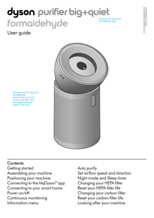
S V 12 J N .00000 P N .000000-00-00 00.00.00 V E R S I O N N O .01ContentsGetting startedAssembling your machine Positioning your machineConnecting to the MyDyson™ a pp Connecting to your smart home Power on/offContinuous monitoring Information menuAuto purifySet airflow speed and direction Night mode and Sleep timer Changing your HEPA filter Reset your HEPA filter life Changing your carbon filter Reset your carbon filter life Looking after your machineDyson purifier big+quiet formaldehyde logo.formaldehyde.real time.Hidden wheelsEasy to manoeuvre across a room – designed for hard surfaces.Carbon filterfilter is wrapped A real-time LCD display screen reports indoor air quality.on hard surfaces.Assembling your machineUse both hands to lift your machine out of the box, by its base.Your machine comes with a HEPA filter, carbon filter and permanent catalytic filter. These are already installed in your machine.Lift the conic amplifier out of the box and place it on the top of your machine.Rotate the conic amplifier until it clicks securely into place.Plug in and press the power button on the screen or remote control.Place the remote control on the front of yourmachine with the buttons facing down.The image demonstrates the location of the standby button and remote control.Image demonstrates how to assemble theDyson purifier big+quiet formaldehyde’s conic amplifier. Position and twist. A click indicates a secure lock.Positioning your machineYour machine is fitted with wheels to make it easier to move.Position your machine on a level floor.For the most effective purification, position your machine on the edge of the room at least 1 metre from the wall, with the conic amplifier pointing to the furthest point, along the wall.You can also position your machine facing diagonally acrossthe room.The purifier positioned on the edge of a room. A blue arrow shows the conic amplifier direction, pointing to furthest point, along the wall.The purifier positioned on the edge of a room. A blue arrow shows the conic amplifier direction, pointing diagonally across the room.Connecting to the MyDyson™ a ppConnecting to your smart homeTake full control with the MyDyson™ a pp and access step-by-step setup and support, control how and when your Dyson air purifier operates, monitor air quality with visual updates and automatically keep up to date with the latest software updates.Download the MyDyson™ a pp from the App Store or Google Play.Open the app and follow the on-screen instructions to create a new account.Apple and the Apple logo are trademarks of Apple Inc., registered in the U.S. and other countries. App Store is a service mark of Apple Inc., registered in the U.S. and other countries.Google Play and the Google Play logo are trademarks of Google Inc.The Android robot is reproduced or modified from work created and shared by Google and used according to terms described in the Creative Commons 3.0 Attribution License.Using Amazon AlexaAsk Alexa to enable the Dyson skill – to help control your air purifier. Set a routine that automates how your machine works with other devices in your home.Using Google AssistantControl all of your connected purifiers with Google or set a routine to automate how your machine works with other devices in your home. Just say “Hey Google” to get started.Using SiriConnect your Dyson machine to Siri Shortcuts to control it by voice onyour Apple device.Power on/offPress the Stand-by on/off button on your Dyson air purifier or remote control to start/stop your machine. It will continue to monitor the air quality.Continuous monitoring is turned off by default. You’ll need to activate it to see your historic AQ data.With continuous monitoring active, your Dyson air purifier will gather air quality and temperature information, displaying iton the LCD screen and in the MyDyson™ a pp.Continuous monitoring on/offYou’ll be prompted to activate Continuous monitoring on the MyDyson™ a pp. To turn it on or off using the remote control, press and hold the Auto mode button for five seconds. The LCD screen will indicate the Continuous monitoring status.Wi-Fi connectivityWi-Fi is turned on by default. To turn the Wi-Fi on or off, press and hold the Stand-by on/off button on your machine for five seconds.Continuous monitoring The remote control with the Stand-by button on the top left.Information menuPress this button to scroll through information monitored by your Dyson air purifier.Information about air quality, temperature, humidity and filter levels is shown on the LCD screen.When a particular type of pollutant causes air quality to decrease, a symbol for the pollutant will show on the LCD screen.Volatile organic compoundsVOCs are potentially harmful odours found in cleaning products, paints and furnishings.The current status of connection to theIndoor temperatureMonitor the ambient temperature of the room.Particulate matter (PM2.5)Microscopic particles up to 2.5 microns in size, suspended in the air we breathe. These include smoke, bacteria and allergens.Indoor humidityThe amount of water vapour in the air, shown as a percentage.Nitrogen dioxide and other oxidizing gases Potentially harmful gases released into the air by combustion from cooking and vehicle exhaust emissions.Particulate matter (PM10)Larger microscopic particles up to 10 microns in size, suspended in the air we breathe. These include dust, mould and pollen.Indoor air qualityAir quality graph shows the last12 seconds of data.Formaldehyde (HCHO)A common indoor pollutant released for many years from furnishings, floorings and glue.Carbon dioxide (CO 2)CO 2 can build up indoors without adequate ventilation, which can impact cognitive function.The remote control with the information button highlighted on the right hand side.In Night mode, your Dyson air purifier will continue to clean the air quietly, in a lower airflow speed with its LCD screen dimmed. Press the Night mode and Sleep timer button to scroll through the timer options.Night mode and Sleep timerSet your air purifier to Auto mode and the on-board sensors willintelligently adjust the settings of the machine according to the air quality.Air quality: your machine will pause when the target air quality has been reached, switching on again when the air quality levels drop.Airflow speed: the airflow speed will increase to its maximum until the target air quality has been reached.Increase or decrease the airflow speed and change air direction from 0° to 50° using the remote or MyDyson™ a pp.Select Breeze mode by repeatedly pressing down on the airflow direction button until it activates or by using the MyDyson™ a pp.Auto purifySet airflow speed and directionThe remote control with the Auto mode button highlighted on the left hand side.The remote control with the Night mode button on the bottom right and Sleep timer button on the bottom left.running low. Replacement filters are available to buy on www.dysoncanada.caRemove the conic amplifierSlide the Release button on the back of the conic amplifier to unlock. Lift the conic amplifier off your machine.Lift the outer cover off the base of your machine.Remove the filterThe HEPA filter is located in the outer cover. Press the filter release buttons located on the inner rim and lift the outer cover off the filter.Dispose of the filter.Install a new filterRemove your replacement filter from any packaging. Place the filter on the base of your machine.Place the outer cover over the filter and press down until it clicks securely into position.Place the conic amplifier on your machine and rotate until it clicks securely in position.Plug in, switch on and reset your filter life.Reset your HEPA filter lifeIt’s important to reset the filter life after replacing your filter.Press and hold the Night mode button on the remote control.The LCD screen on your machine will count down from five, until a tick appears on the screen.The filter life has been reset and your machine is ready to use.Pressing the night mode button on the bottom right of the remote control for 5 seconds.running low. Replacements are available to buy on www.dysoncanada.caRemove the conic amplifierSlide the Release button on the back of the conic amplifier to unlock. Lift the conic amplifier off your machine.Lift the outer cover off the base of your machine.Reset your carbon filter lifeIt’s important to reset your filter life after you have replaced your filter.Press and hold the down airflow direction button on the remote control. The LCD screen on your machine will count down from five, until a tick appears on the screen.The filter life has been reset and your machine is ready to use.Remove the filterThe carbon filter is wrapped around the central body of your machine. Pull each of the four clips towards you to release the filter.Dispose of the filter.Install a new filterRemove your replacement filter from any packaging.Wrap the filter around the base of your machine, fit the clips in position and push each one to secure the filter.Place the outer cover and HEPA filter back in position on the base of your machine.Place the conic amplifier on your machine and rotate until it clicks securely in position.Plug in and switch on, and reset your filter life.Holding down theairflow direction button on the right hand side of the remote control for 5 seconds.machine. A clickPlace the outer cover position on the base of your machine.Looking after your machineTo always get the best performance from your Dyson air purifier, it’s important to regularly clean it and check for blockages.Cleaning your machine If your machine is dusty, wipe with damp, lint-free cloth.Check the sensor inlets on the left hand side of the conic amplifier for dust and debris.Look for dust and debris in the outer cover and in the conic e a soft brush to remove dust and debris.Don’t use detergents or polishes to clean your machine.Eye icons identify where a user should regularly check for dust and debris, in outer cover and conic amplifier. Use a soft brush on the areas highlighted to clean the purifier.。
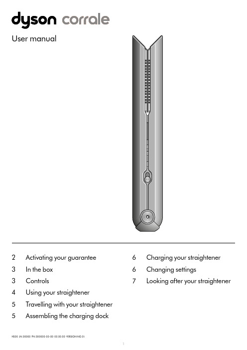
Dyson Corrale 直发器使用说明书
Target temp
210 185 165
Current temp
Adjusting the temperature Press the Temperature (+/-) control buttons to select the temperature that suits your hair type and styling preference.
Reactivating your straightener Insert the Flight-ready tag back into your straightener.
Assembling the charging dock
Your dock can be used as a charging dock or a stand to store your Dyson Corrale™ straightener.
To achieve enhanced styling with less reliance on heat, Dyson engineers developed flexing plates. Made from materials selected for their flexibility, strength and thermal conduction, they shape to gather and control hair.
Charging when travelling Just check if you need a travel adaptor. The Magnetic 360° charging cable is suitable for use with all mains electricity supplies.
空氣盒子 V6 安裝指南说明书
AI-1001W V6 空氣盒子V6產品規格包裝內容1. 空氣盒子V6 x 12. 電源供應器(5V/2A) x 1 及USB 線x 13. 壁掛支架及螺絲包x 1組4. 安裝指南x 15. 簡易故障排除指南x 16. Wi-Fi 天線(短) 及NBIoT天線(長) 各一本體LED指示燈號說明系統狀態Wi-Fi使用安全須知為了有效檢測和檢索環境數據,請詳閱下列使用安全須知:1.請安裝在通風良好的地方。
2.進氣口必須保持清潔,並應定期檢查。
3.安裝地點必須具備電源插座、良好的NB-IoT 或Wi-Fi等訊號並可24小時連上網際網路。
4.安裝地點必須於高於地面100公分或以上的位置。
5.安裝地點必須在有條件限制的半戶外有遮蔽空間下,以有效獲取環境感測資訊,例如:陽台、屋簷下或通風良好的開放空間,避免日光直射或淋雨。
6.請採直立式安裝,請勿橫置,以利設備進風口處的空氣對流。
7.請勿堵塞設備進風口處,平時注意保持進風口暢通。
8.請勿將產品安裝在直接暴露於陽光或有反射光源的地方。
9.請勿靠近火源、暖氣或使用於極端溫、濕度的環境中。
10.請勿向設備直接注入氣體、污染物或直接噴入煙霧。
11.請勿將本產品安裝於沒有良好遮蔽的戶外環境,請避開任何極端天氣的環境,例如颱風、沙塵暴、暴雨等。
12.請勿安裝於具腐蝕性的環境中,例如:含有鹽分的空氣中、酸鹼等腐蝕性氣體中、存放化學或任何腐蝕性液體的地方。
建議每個產品的安裝距離保持150公尺以上,以實現地圖定位和空氣質量數據的準確性。
如有使用問題,請聯繫客戶服務中心******************.tw。
硬體安裝✧請先確定您的手機可以正常上網。
✧您若採用NB-IoT 連線方式請先參考下面操作說明,小心地把NB-IoT SIM 卡安裝入空氣盒子裡。
1.請用十字起子取下底部的四顆固定螺絲。
2.再小心將底座抽出,本模組採用Nano SIM 請小心把SIM卡取下,並將金屬接點面朝上斜口朝左,小心地將把SIM卡推入卡槽中,會聽到咯一聲代表正確插好。
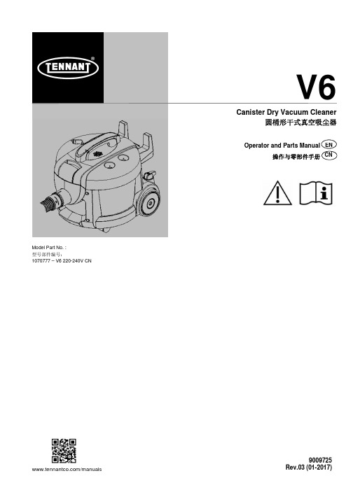
Tennant V6 圆桶形干式真空吸尘器操作与零部件手册说明书
ENCanister Dry Vacuum Cleaner圆桶形干式真空吸尘器/manuals V6Model Part No. : 型号部件编号:1070777 – V6 220-240V CN9009725Rev.03 (01-2017)Operator and Parts Manual 操作与零部件手册CNENGLISH ENIntroductionThis manual is furnished with each new model. It provides necessary operation and maintenance instructions and replacement parts information.Read all instructions before using machine.Intended UseThis canister dry vacuum cleaner is suitable for picking up dray, non-flammable dust and debris in an indoor environment. It is not suitable for picking up liquids or hazardous materials.General InformationThis machine will provide excellent service. However, the best results will be obtained at minimum costs if:• The machine is operated with reasonable care.• The machine is maintained regularly - per the machine maintenance instructions provided.• The machine is maintained with manufacturer-supplied or equivalent parts.Protect the EnvironmentPlease dispose of packaging materials and used machine components in an environmentally safe way according to local waste disposal regulations. Always remember to recycle.Machine DataPlease fill out at time of installation for future reference. Model No. - Serial No. - Installation Date -Technical Specifications Model V6Voltage 220-240V Frequency 50-60Hz Rated Power 1200W Airflow Rate 40 l/s Bag Capacity9 L Power Cord Length 12mFiltration (HEPA) 99.95% @ 0.3 micron Weight7.6 kg Size (Height x Width)36 x 40cmSound Pressure Level L pA ************Sound Uncertainty K pA 1.645 dBA Sound Power Level L wA + uncertainty K wA73 dBA Constructions Class IIVibrations at Controls <2.5 m/s² Protection GradeIP20Tennant CompanyPO Box 1452, Minneapolis, MN 55440 USA Phone: (800) 553-8033 or (753) 513-2850 Tennant Cleaning Systems & Equipment Co., Ltd Building 1, No. 3777 Caoying Road Qingpu Shanghai, China 201712 phone: (86-21) 6922-53333 fax: (86-21) 6922-5151Original Instructions. Copyright ©2012 Tennant Company.All rights reserved. Printed in China.Specifications and parts are subject to change without notice.IMPORTANT SAFETY INSTRUCTIONSThis symbol warns the operator of hazards and unsafe practices which could result in severe personal injury or death.WARNING - To reduce the risk of fire, electric shock, or injury:1. Do not leave appliance when plugged in.2. Unplug cord from outlet when not in use and before servicing.3. Do not use outdoors or on wet surfaces. This machine is forindoor and dry use only.4. Do not allow to be used as a toy. Close attention is necessarywhen used by or near children.5. Use only as described in this manual. Use only manufacturer'srecommended attachments.6. Operators shall be adequately instructed on the use of thismachine.7. This machine is not intended for use by persons (includingchildren) with reduced physical, sensory or mental capabilities, or lack of experience and knowledge, unless they have been given supervision or instruction concerning use of the appliance by a person responsible for their safety.8. Do not use with damaged cord or plug. Regularly inspect cordand plug for damage. If the cord is damaged, it must bereplaced by the manufacturer, its service agent or a similarly qualified person in order to avoid a hazard.9. Do not pull or carry by cord, use cord as handle, close a dooron cord, or pull cord around sharp edges or corners. Do not run appliance over cord. Keep cord away from heated surfaces.10. Do not unplug by pulling on cord. To unplug, grasp the plug,not the cord.11. Do not handle plug or appliance with wet hands. 12. Connect to a properly grounded outlet only.13. Make sure the power voltage corresponds with the voltageshown on the machine's rating plate.14. Do not put any object into openings. Do not use with anyopening blocked; keep free of dust, lint, hair, and anything that may reduce air flow.15. Keep hair, loose clothing, fingers, and all parts of body awayfrom openings and moving parts.16. Turn off all controls before unplugging.17. Do not use to pick up flammable or combustible liquids, suchas gasoline, or use in areas where they may be present. 18. Do not pick up any type of fluid, hazardous dust or toxicmaterials.19. Do not pick up anything that is burning or smoking, such ascigarettes, matches, or hot ashes.20. Use extra care when cleaning on stairs.21. Do not use without dust bag and/or filters in place.22. If using an extension cord make sure the cord rating is suitablefor this machine.23. Do not modify machine from its original design.24. Keep children and unauthorized persons away from themachine when in use.25. All repairs must be performed by a qualified service person.Use only manufacturer-supplied or equivalent replacement parts.26. Do not expose to rain or moisture. Store indoors only.SAVE THESE INSTRUCTIONSStorage and TransportingCarefully wrap power cord around machine's cord hooks and store machine in a dry indoor environment. Do not expose machine to rain or moisture. Lift machine by the carrying handle to transport.Name ofpartsHazardous SubstanceLead (Pb) Mercury (Hg) Cadmium (Cd) Hexavalent chromium Cr(VI) Polybrominatedbiphenyls (PBB)Polybrominateddiphenyl ethers(PBDE)PCBA andassmy X O O O O OMotor O O O O O O Cover O O O O O O Other O O O O O O This form is prepared in accordance with SJ/T11364.O Indicating that the content of all hazardous substances in the uniformity of the material in the GB / T26572 below limit requirementsX Indicates that the hazardous substance is present in at least one homogeneous material of the part in excess of the limits specified in GB / T26572操作CN介绍本手册提供各款最新型号的说明。
戴森 吸尘器 用户手册说明书
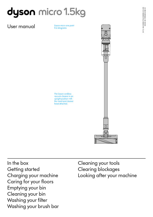
User manualIn the boxGetting startedCharging your machine Caring for your floors Emptying your bin Cleaning your bin Washing your filterWashing your brush barS V 12 J N .00000 P N .000000-00-00 00.00.00 V E R S I O N N O .01Cleaning your tools Clearing blockagesLooking after your machineThe Dyson cordless vacuum cleaner in an upright position with the wand and cleaner head attached.Dyson micro one point five kilogramsIn the boxWand clipClips to your vacuum's wand to hold tools.A plastic clip that attaches to the wandGetting startedCharging your machineFor the best experience, we recommend fully charging your machine, and any additional batteries, as soon as you open the box and after every clean.The LED light on the end of the handle will flash when the power is running low and you need to put your battery on to charge.Connect the charger directly to the charging point on the base of the handle of your machine. You can also connect to your dock as shown in the installation instructions supplied with your dock.The LED light on the end of the handle will pulse with a blue LED light when charging, and the light will go out when fully charged.It can take up to four hours to fully charge your battery. Your battery has been designed to be left on charge.Your machine won’t operate or charge if the ambient temperature is below 5°C (41°F). This is designed to protect both the motor and battery.You can help prolong the battery life by leaving your machine to cool downbefore recharging.Caring for your floorsCheck that the underside of the cleaner head or tool is clean and free from any objects that may cause damage.Before vacuuming your flooring, rugs, and carpets, check the manufacturer’s recommended cleaning instructions.This machine is designed for use on hard floors. The brush bar on your machine can damage certain flooring. Some rug materials may fuzz if a rotating brush bar is used when vacuuming. If this happens, we recommend vacuuming without the motorised floor tool and consulting with your flooring manufacturer.Washing your filterWash your filter at least once a month to maintain the best performance. Make sure the filter is completely dry before refitting.Twist off your filterDon’t put any part of your machine in a dishwasher or use detergents, polishes or air fresheners.Turn your filter anti-clockwise and pull it away from your machine.Before washing your filter, tap it gently over a bin to remove any loose dust and debris.Wash your filterWash the outside of the filter, rubbing with your fingers to remove the dirt. Carefully rinse the inside filter, without allowing water to fill the filter. Repeat these steps until the water runs clear.Shake and dryEmpty the filter and shake firmly to remove excess water.Keep shaking until there’s no water coming from the filter.Place your filter end up, as shown.Leave your filter to dry for at least 24 hours in a well-ventilated, warm place. Don’t dry your filter in a tumble dryer, microwave or near a naked flame. Important: your filter must be completely dry before you put it back into the machine. Your machine could be damaged if used with a damp filter.Refit your filterTo refit your filter, slide it onto the handle and turn it clockwise until it clicks into place.Your filter may need more frequent washing if you vacuum fine dust,use Max mode frequently or use with the bin full.A hand holding the filter with thenarrow end pointing downwards withdroplets of water being shaken from thefilter and again, with the end pointingdownwards shaking water out.The filter is left to drywith the pleated filterend facing upwards.Filter with hand overthe open end witharrows showing ashaking motion.Filter held in uprightposition, with the widerend in the palm of ahand. Water runningfrom a tap into thenarrower end.The filter is located at therear of your machine.Holding the filterby the hard, plasticend, tap the otherend over the bin.Washing your brush barRemove brush barDon’t put any part of your machine in a dishwasher or use detergents, polishes or air fresheners.Press the cleaner head release button to remove it from the wand.Pull the brush bar off the end cap and put the end cap to one side, don’t wash it.Wash and dry brush baror dirt. Keep washing until the water runs clear.Stand the brush bar upright and leave for at least 24 hours to dry.Replace your brush barsMake sure your brush bar is completely dry before refitting.Rotate the end cap until it clips securely back into position.The cleaner head housing is not washable and should only be wiped over with a damp lint-free cloth.Cleaning your toolspolishes or air fresheners.Light pipe crevice tool Mini motorised toolClearing blockagesIf your machine detects a blockage, the motor will pulse six times. You won’t be able to use your machine until the blockage has been cleared.If you try to use your machine when the motor is pulsing, it will automatically cut out.Leave your machine to cool down before looking for blockages and, for yoursafety, take care not to touch the power button.Disconnect your machine from the charger before looking for blockages. Be careful not to touch the trigger and be aware of sharp objects.Leave your machine to cool down before looking for blockages.Don't use your machine when looking for blockages as this could cause injury.With the wand removed from the machine, check for blockages at both ends of the wand.With the bin removed, check for blockages, paying particular attention to the air inlet, located at on the right–hand side of the machine just below the point where the bin joins the main body of the machine.Turn the cleaner head over to check for obstructions on the brush bar and air inlet.runner.Remove any obstructions from the brush bar.Looking after your machineTo always get the best performance from your machine, it’s important to clean it regularly and check for blockages.Look after your machineIf your machine is dusty, wipe with a damp lint-free cloth.Check for blockages in the cleaner head, tools and main body of your machine. Wash your filter regularly and leave to dry completely.Don’t use detergents or polishes to clean your machine.Look after your batteryTo get the best performance and life from your battery, use Eco mode.Your machine won’t operate or charge if the ambient temperature is below 5°C(41°F). This is designed to protect both the motor and battery.Your serial numbersYou can register your machine using the serial number found on the bottomof your machine.You can find your serial numbers on your machine, battery and charger.Use your serial number to register.。
戴森吸尘器优惠范文
第一篇戴森吸尘器优惠WYSON吸尘器使用说明》初次开箱,可以直接使用。
等到电用完了,机器就不能工作。
插上电源充电5小时,充电的时候机器亮蓝灯,充满了灯就熄火了。
充满电请立即拔掉插头,避免安全隐患。
如果超过3个月以上不使用吸尘器,请把电池拆下来,在阴凉通风处保存(只要拧开螺幺幺,电池就能取下)。
机器有大、小两档吸力。
请按机器背后圆形MAX按键调节吸力,DC62按住红色开机键的时候按max按键调节吸力,大吸力最多工作6分钟,小吸力工作20分钟左右。
垃圾满了,按红色按键倒出垃圾。
注意垃圾桶不能水洗,机器也不能吸水。
机器进水会导致机器报废不能使用,请特别注意。
机器内部有一个紫色圆柱形hepa滤网,上而有水龙头标志,这个滤网每3个月淸洗一次。
洗好以后一泄要晾干,需要晾24个小时。
晾干以后放入机器,可以重复使用。
吸地面的炭纤维涡轮吸头不能水洗。
如果滚轮上缠了头发,可以拿一元硬币,根据吸头上的指示转开,取出滚轮淸理。
第二篇戴森吸尘器优惠《戴森吸尘器》戴森吸尘器英国知爼工程师及发明家詹姆士・戴森日前宣布,由英创建的家电品牌戴森正式进军中国市场,为中国消费者带来包括Ball技术、手持式吸尘器械以及气流倍增器风扇和暧风器等在内的一系列戴森公司最新技术与产品。
31年前,戴森创造了全球第一款吸力永不减弱的无尘袋吸尘器,戴森品牌应运而生。
戴森原创的气流倍增器是全球首款无叶风扇,该项技术通过环状气流倍增器中的环形狭缝对气流进行加速,形成由弧形翼面引导喷射方向的喷射气流,并将周帀的空气卷入气流,使用安全且易于淸洁。
9月1日,戴森在上海第一八佰伴开出在中国市场的第一家专卖店,其后在北京金融街开岀第二家专卖店,年内讣划在北京和上海共开8家专卖店。
戴森还有意在广州、深圳等其他市场进行布局。
此外,电商市场也是戴森产品销售的另一个重要渠道。
戴森公司是一家总部设在英国的工程技术创新公司,英产品行销全球45个国家。
在创始人詹姆斯•戴森的领导下,戴森公司为吸尘器,洗衣机,自动吸尘器以及手持吸尘器设计并研发新技术。
海尔戴森2007年Honda ENGINEERING DX LX EX发动机类型说明书

•
Electronic Brake Distribution (EBD)
•
Daytime Running Lights (DRL)
•
Outboard Lower Anchors and Tethers for Children (LATCH) •
Child-Proof Rear Door Locks
10. 3 / 7.9
15" with Full Covers P195/65 R15 89H
16" with Full Covers P205/55 R16 89H
• • • 24. 2 /10.0 • 2.67 35.4
10. 3 /10. 2
16" Alloys P205/55 R16 89H
12.0 88.4
SEATING
Driver’s Seat with Manual Height Adjustment
•
Adjustable Head Restraints
•
Fold-Down Rear Seatback
•
•
•
•
•
•
60/40 Split
EXTERIOR MEASUREMENTS Wheelbase (in.) Length (in.) Height (in.) Width (in.) Track (in., front/rear) Curb Weight (lbs., MT/AT)
• ULEV-2
• •
EX In-Line 4-Cylinder Aluminum-Alloy
179 9 140 @ 6300 128 @ 4300
10.5 :1 16-Valve SOHC i-VTEC
DC52.62中文使用说明书
Dyson DC59/62无线吸尘器使用说明及日常保养注意事项1、主机部分:●电机和集尘盒不能进水,否则会烧毁电机。
●机器有高低2个档位,高档持续使用时间不宜太长,以免电机持续高温,影响使用寿命。
建议仔细阅读原厂说明书,都是图示的,简单易懂!2、电动吸头:●DC59/DC62的涡轮地板吸头,涡轮毛发吸头都是电流驱动,所以吸尘器不能吸有水的东西,吸头不能进水,中间的旋转毛刷轴可以拆下定期清理。
●第一次拆卸很关键,建议用一元硬币插进凹槽,沿着开锁方向用大力旋转,盖子打开后,毛刷轴抽出来冲洗,请勿用力拉刷毛,冲洗后晾干24小时候装回。
3、清洁事项:●透明的集尘盒外罩可以拆下来,不可水洗,用湿布或湿巾纸擦干净可以了。
●透明的集尘盒中间紫色(直驱版红色)的网状集尘器不可拆卸,不能水洗,电机电池进水就会报废,定期拿自带的伸缩小毛刷清理即可。
●透明集尘盒的拆卸方法:按下集尘盒舱门的红色按键,舱门打开后,再次按下按键到底,同时用另外一只手握住集尘盒的吸头接口向上侧一下,就可以取下透明的集尘盒了。
里面紫色(直驱版红色)的过滤器不可拆卸,所以只能用毛刷清洁,水洗容易弄湿电池马达部分。
●机器顶部的蓝色锥形HEPA过滤网可以抽出来水洗,但是不用洗的太频繁,灰尘拍净即可。
建议一个月清洗一次,不要搓洗,用水冲洗,晒干24小时装回即可。
4、电池保养:a.充电电池是锂电池,没有记忆,但是建议尽量每次用完后再充。
充电只需要大概3.5小时。
充电指示灯在电池把手处,蓝灯长亮表示正在充电,熄灭表示充电完成了。
b.电池用完电后,不要立刻充电,要让电池冷却几分钟后再充电,这点很重要,特别是使用MAX模式的时候,电池发热的情况下。
5、电池指示灯:a.充电指示灯在电池上面,蓝灯长亮表示正在充电,熄灭表示充电完成了。
b.电池部位的灯出现蓝色闪烁表示电力不足,出现黄色表示电池温度过低或者过高,出现红色闪烁表示电池故障。
c.主机尾部中央圆形MAX按键,是高低挡切换开关,需要红色扳机扣住运行状态下才能切换超强和普通模式,MAX键蓝色灯亮起,表示正在使用超强MAX模式(使用6分钟左右);MAX键没有亮灯表示正在使用普通模式(使用20分钟左右),一般使用普通模式即可。
戴森加湿空气净化器说明书
Indoor air quality – 24hrs Monitor the current air quality with a graph showing the last 24 hours of data.
Indoor humidity The amount of water vapor in the air, shown as a percentage.
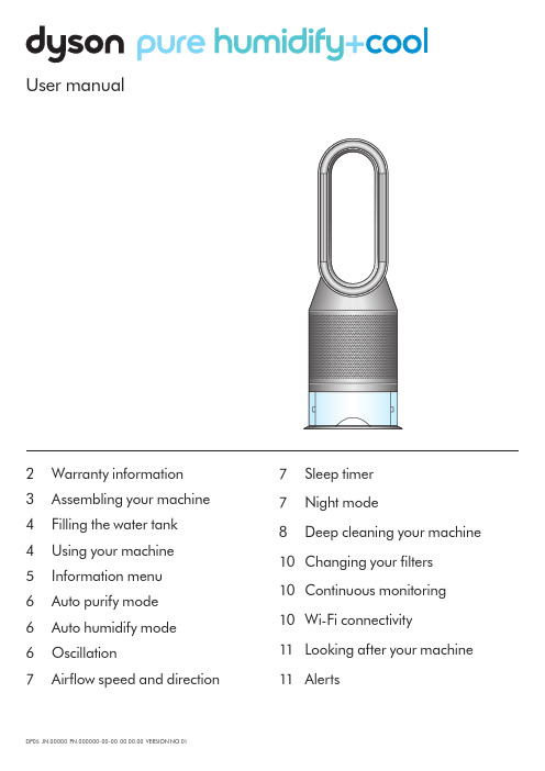
Thank you for choosing to buy a Dyson purifying humidifying fan.
Set up your machine quickly, with step-by-step support
– Personalize your settings for maximum comfort.
Before you remove the water tank, make sure humidification modes are turned off.
Push down the water tank release buttons on the sides of your machine.
Clik
Use both hands to lift your Dyson purifying humidifying fan out of the box, by its base.
Don’t lift it out by the amplifier loop.
Push down the Shroud release buttons on both sides of your machine to release the shrouds.
Push down the Shroud release buttons on both sides of your machine to release the shrouds.
戴森超音速吹风机用户手册说明书
目录页数特性和优势3零配件组装6使用和操作7 LED显示灯的故障诊断7滤网清洁8零配件指导9部件识别图(分解图)10热线诊断12安全警告20戴森两年保修期21高压高速的气流高速喷射而出,实现可控的吹干和造型。
周围的空气被吸入并产生形成3倍的气流。
戴森第九代数码马达其转速相比其他吹风机马达快8倍,而重量却减半。
在手持处的气流倍增技术每秒推动13公升的空气。
全面稳定的气流快速吹干不只是需要高速的气流,对双组加热元件进行智能调整。
因为戴森独有设计的减震系统。
戴森第九代数码马达每分钟旋转高达110,000次,产生一种人耳听不到的频率。
没有格栅的出风口设计,带给客户更好的体验效果负离子技术避免静电产生。
内置强劲数码马达戴森第九代数码马达叶片增加至13片,每分钟旋转高达110,000次。
马达旋转时产生3.5kPa的压力。
转速相较于其他吹风机一部分马达高8倍,而重量却减少了一半。
简易的过滤器清洁方法只需转动一下,松开即可清洁过滤器。
4 supersonic环形元件构造未产生加热情况下的环形加热双栈元件磁性连接设计唯一一款配有磁性连接设计的机器, 可以快速方便地更换或转动风嘴减震支架橡胶安装架可帮助防止马达接触 手柄时的震动,从而降低马达和 壳之间的噪音传递只需转动一下,松开 即可清洁过滤器特性和优势脉宽调制精确控制加热元件LED 显示灯清晰地显示选项设置4档精确温度设置 • 快速吹干和造型 • 常规吹干• 轻柔吹干(头皮模式) • 恒冷风 3档风速设置: • 快速 • 常规 • 造型 Cool shot 按钮 自定义设计发型.消音技术同时降低了机器内部和外部的噪音,但是 并没有牺牲其干发的速度。
简易的存储方式为了快速,方便的存储,可以 使用挂绳和防滑垫磁性连接设计独一无二的吹风机体验,磁性连接设计,可以快速方便地更换或转动风嘴。
隔热可触碰技术通过Heat Shield 隔热技术,风嘴表面可保持低温, 即便长时间使用也可随时触碰风嘴。
Dyson Zone 空气净化耳机 用户手册说明书
X X X X J N .00000 P N .000000-00-00 00.00.00 V E R S I O N N O .01目录包装内附下载 MyDyson™应用程序开始使用组装耳机安装日常/过滤面罩为耳机配对为耳机充电气流控制使用音频主动降噪音频操纵杆LED 指示灯更换滤网清洁空气净化耳机重新组装耳机清洁日常面罩可替换过滤面罩部分配件可能未包含在内。
您可前往戴森官方渠道购买。
USB-C 充电线飞行音频转接组件1无接触式面罩清洁刷Dyson Zone™空气净化耳机下载 MyDyson™ 应用程序作为使用体验的重要组成部分,MyDyson™应用程序让您可以随时随地控制您的 Dyson Zone™ 空气净化耳机。
现在就下载该应用程序,获取更多功能和最新信息。
从 App Store 或安卓(Andriod)应用商店下载MyDyson™应用程序。
打开应用程序,按照屏幕 上的说明创建新账号。
Apple 和 Apple 标志是 Apple Inc.在美国和其他国家的注册商标。
App Store 是 Apple Inc.在美国和其他国家的注册服务商标。
Android 和 Android 徽标是 Google Inc.的商标。
1. 鎏光金及普鲁士蓝旗舰版专属。
组装耳机插入滤网拧下两个耳罩盖。
握住滤网的边缘,将其放入耳罩中。
重新装上盖子,旋转并卡入原位。
调节耳机戴上耳机。
滑动两侧头带来调节,直至佩戴舒适。
安装无接触式面罩调节无接触式面罩调整面罩,直至佩戴舒适状态。
靠近但不接触您的面部。
气流将自动开始输送。
取下面罩外的包装,将面罩完全展开。
将面罩置于面部下方,通过磁性连接组件安装到耳罩两侧。
抬起面罩,遮盖口鼻。
x2安装日常/过滤面罩安装日常/过滤面罩将日常面罩或过滤面罩推入无接触式面罩中,确保顶部与底部安装位置均连接到位。
可重复使用的日常面罩。
可替换的过滤面罩。
这些配件可以通过戴森官方渠道再次购买。
安装无接触式面罩将无接触式面罩置于面部下方,通过磁性连接组件安装到耳罩两侧。
戴森手持式吸尘器说明书
TO REDUCE THE RISK OF FIRE, ELECTRIC SHOCK, OR INJURY: 1. Do not charge the Dyson handheld vacuum outdoors, in a bathroom or within 10 feet of a pool. 2. Do not use outdoors or on wet surfaces. 3. Do not allow to be used as a toy. Close attention is necessary when used by or near children. 4. Use only as described in this manual. Use only Dyson recommended accessories and replacement parts. 5. Do not use with damaged cable or charger. If the Dyson handheld vacuum is not working as it should, has been
OPERATING MANUAL 사용설명서 操作手册 操作手冊
ASSEMBLY 조립 组装 組裝
clik
2
WASH FILTER Wash filter with cold water at least every month.
month
개월 个月
필터 청소 최소한 한 달에 한 번 찬물로
個月
필터를 세척해 주십시오.
SAVE THESE INSTRUCTIONS
THIS HБайду номын сангаасNDHELD VACUUM IS INTENDED FOR DOMESTIC HOUSEHOLD AND CAR USE ONLY.
戴森 AC6678 无线空气净化器 用户手册说明书
AC66781 重要事项安全使用本产品之前,请仔细阅读本用户手册,并妥善保管以备日后参考。
危险• 切勿让水或任何其它液体或易燃性清洁剂进入产品,以免发生触电和/或火灾。
• 切勿用水或任何其它液体或(易燃性)清洁剂来清洁产品,以免发生触电和/或火灾。
• 切勿在产品周围喷洒杀虫剂或香水等任何可燃材料。
警告• 在将产品连接电源之前,请先检查产品所标电压与当地的供电电压是否相符。
• 如果电源软线损坏,为避免危险,必须由制造厂或其维修部或类似的专职人员来更换。
• 如果插头、电源线或产品本身受损,请勿再使用本产品。
• 本产品适合由 8 岁或以上年龄的儿童以及肢体不健全、感觉或精神上有障碍或缺乏相关经验和知识的人士使用,但前提是有人对他们使用本产品进行监督或指导,以确保他们安全使用,并且让他们明白相关的危害。
不得让儿童玩耍本产品。
请勿让儿童在无人监督的情况下清洁和保养产品。
• 请勿堵塞进风和出风口,例如不要将物体放置在出风口上或进风口前方。
• 确保异物未通过出风口进入产品内部。
小心• 本产品不能替代正常通风、日常吸尘或者在烹饪时使用的抽油烟机。
• 如果连接产品的电源插座接触不良,则产品的插头可能会变得很热。
确保所连接的电源插座接触良好。
• 一定要在干燥、稳固、平整且水平的表面上放置和使用本产品。
• 产品的后侧及两侧均要留出至少 20 厘米的空间,产品上方至少要留出 30 厘米的空间。
• 切勿在本产品上放置任何物品。
• 请勿坐在或站在产品上面。
坐在或站在产品上面可能导致潜在的人身伤害。
• 切勿将产品直接放在空调下方,以防冷凝水滴到产品中。
2ZH-S简体中文3ZH-S • 打开产品电源之前,务必确保已经正确安装所有过滤网。
• 只能使用飞利浦专门为本产品设计的原装过滤网。
切勿使用任何其它过滤网。
• 燃烧滤网可能会造成不可逆转的人体危害和/或危及其他生命。
请勿将滤网用作燃料或类似用途。
•请勿用硬物敲击本产品(尤其是进风口和出风口)。
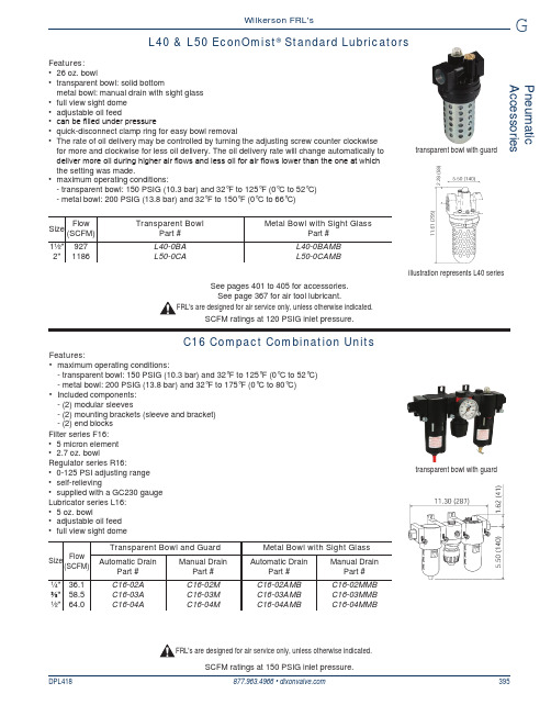
戴森(Dixon)胸部阀门(FRL)L40和L50 EconOmist标准油帘说明说明书
Pneumatic AccessoriesGDPL418877.963.4966 • 395Wilkerson FRL'sL40 & L50 EconOmist ®Standard Lubricatorsillustration represents L40 seriestransparent bowl with guardFeatures:• 26 oz. bowl • t ransparent bowl: solid bottom m etal bowl: manual drain with sight glass • f ull view sight dome • a djustable oil feed • c an be filled under pressure • q uick-disconnect clamp ring for easy bowl removal • T he rate of oil delivery may be controlled by turning the adjusting screw counter clockwise for more and clockwise for less oil delivery. The oil delivery rate will change automatically to deliver more oil during higher air flows and less oil for air flows lower than the one at which the setting was made.• maximum operating conditions:- t ransparent bowl: 150 PSIG (10.3 bar) and 32°F to 125°F (0°C to 52°C)- m etal bowl: 200 PSIG (13.8 bar) and 32°F to 150°F (0°C to66°C)C16 Compact Combination Unitstransparent bowl with guardFilter series F16:• 5 micron element • 2.7 oz. bowlRegulator series R16:• 0-125 PSI adjusting range •s elf-relieving • s upplied with a GC230 gauge Lubricator series L16:• 5 oz. bowl • a djustable oil feed • f ull view sight dome Features:• maximum operating conditions:- t ransparent bowl: 150 PSIG (10.3 bar) and 32°F to 125°F (0°C to 52°C)- m etal bowl: 200 PSIG (13.8 bar) and 32°F to 175°F (0°C to 80°C)• Included components: - (2) modular sleeves - (2) mounting brackets (sleeve and bracket) - (2) end blocks SCFM ratings at 150 PSIG inlet pressure.FRL's are designed for air service only, unless otherwise indicated.SCFM ratings at 120 PSIG inlet pressure.See pages 401 to 405 for accessories.See page 367 for air tool lubricant.FRL's are designed for air service only, unless otherwise indicated.。
