uvlo低电压锁定
精工电子 S-8333系列是一种由基准电压电路 说明书

S-8333系列 升压 LCD偏压用 1通道 PWM控制DC/DC控制器© Seiko Instruments Inc., 2004-2010Rev.4.0_00S-8333系列是一种由基准电压电路、振荡电路、误差放大电路、PWM控制电路、低电压误工作防止电路(UVLO)、时钟闩锁式短路保护电路等构成的CMOS升压DC/DC控制器。
最低工作电压为1.8 V,最适合于LCD用电源及低电压工作的移动设备。
由于在ROSC端子部连接了电阻,所以可设定内部的振荡频率最大到1.08 MHz为止。
通过在RDuty端子部连接了电阻,故可控制PWM控制电路的最大占空系数。
在电源投入时的软启动功能由基准电压调整方式、最大占空系数调整方式的2种组合而成,即使由于IC外部的原因而导致FB端子电压保持在不足基准电压的状态下,也可以调整最大占空系数来启动提升输出电压。
通过连接在CC端子部的电阻和电容器的值进行相位补偿,成为可以调整增益值的构成。
因此,使每个应用电路均可针对工作稳定度和过渡响应特性进行合适的设置。
基准电压为1.0 V±1.5%的高精度,通过外接的输出电压设定电阻可以得到任意的输出电压。
另外,通过连接在CSP端子的电容器可设定短路保护电路的延迟时间。
因短路最大占空系数的状态若持续,电容器则被充电,经由一定时间后停止振荡工作。
在电源的电压降低到UVLO检测电压以下后,通过将其提升到UVLO解除电压以上即可解除短路保护功能。
因所设定的输出容量的不同而选择使用陶瓷电容器,或是钽电容器。
该产品可进行各种设定以及选择,加上与采用小型封装的特点相结合,可以成为使用方便的控制器IC。
特点•低电压工作: 1.8 V ~ 6.0 V•振荡频率:利用外接电阻可在280 kHz ~ 1.08 MHz之间设定•最大占空系数:利用外接电阻最大可设定到88.5%47 ~ 88.5%(振荡频率 500 kHz以上)47 ~ 80%(振荡频率不足500 kHz)•基准电压: 1.0 V ± 1.5%•工作温度范围:−40 ~ +85°C•UVLO(低电压误工作防止)功能:检测电压在1.5 V ~ 2.3 V之间,可以0.1 V为进阶单位来选择滞后幅度在0.1 V ~ 0.3 V之间,可以0.1 V为进阶单位来选择•时钟闩锁式短路保护电路:可用外接电容器设定延迟时间•软启动功能:软启动时间可在10 ms, 15 ms, 20 ms的3阶段中进行选择调整方式可采用基准电压调整和最大占空系数调整的2种方式•通过外接设定相位补偿:可利用连接在CC与GND端子之间的电阻和电容器来进行调整•无铅、Sn 100%、无卤素*1*1. 详情请参阅“ 产品型号的构成”。
L6599功能(中文)
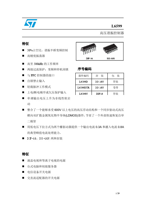
L6599高压谐振控制器特征⏹ 50%占空比,谐振半桥变频控制 ⏹ 高精度振荡器⏹ 高至500kHz 的工作频率 ⏹ 两级过流保护:变频和停机闭锁 ⏹ 与PFC 控制器的接口 ⏹ 自锁禁止输入 ⏹ 轻载脉冲工作模式⏹ 上电/断电顺序或欠压保护输入 ⏹ 单调输出电压上升为非线性软启动⏹ 整合了一个能够承受600V 以上电压的高压浮动结构和一个同步驱动式高压横向双扩散金属氧化物半导体(LDMOS)器件,节省了一个外部快速恢复自举二极管⏹ 用低电压下拉方式为两个栅驱动器提供一个输出电流0.3A 和灌入电流0.8A的典型峰值电流处理能力。
⏹ DIP-16,SO-16N 两种封装特征⏹ 液晶电视和等离子电视的电源 ⏹ 台式电脑和初级服务器 ⏹ 电信设备开关电源 ⏹ 交直流适配器的开关电源框图目录1 驱动描述 . . . . . . . . . . . . . . . . . . . . . . . . . . . . . . . . . . . . . . . . . . . . . . . . . .42 引脚设置 . . . . . . . . . . . . . . . . . . . . . . . . . . . . . . . . . . . . . . . . . . . . . . . . . .52.1 引脚排列 . . . . . . . . . . . . . . . . . . . . . . . . . . . . . . . . . . . . . . . . . . . . . . . . . . . .52.2 引脚功能说明 . . . . . . . . . . . . . . . . . . . . . . . . . . . . . . . . . . . . . . . . . . . . . . . . 53 典型系统框图 . . . . . . . . . . . . . . . . . . . . . . . . . . . . . . . . . . . . . . . . . . . . . . 74 电气数据 . . . . . . . . . . . . . . . . . . . . . . . . . . . . . . . . . . . . . . . . . . . . . . . . . . 74.1 极限参数 . . . . . . . . . . . . . . . . . . . . . . . . . . . . . . . . . . . . . . . . . . . . . . . . . . . . . .74.2 热相关数据 . . . . . . . . . . . . . . . . . . . . . . . . . . . . . . . . . . . . . . . . . . . . . . . . . . . . .85 电气参数 . . . . . . . . . . . . . . . . . . . . . . . . . . . . . . . . . . . . . . . . . . . . . . . . . . . 96 典型的电气性能 . . . . . . . . . . . . . . . . . . . . . . . . . . . . . . . . . . . . . . . . . . . . . .127 应用资料 . . . . . . . . . . . . . . . . . . . . . . . . . . . . . . . . . . . . . . . . . . . . . . . . . . . 157.1 振荡器 . . . . . . . . . . . . . . . . . . . . . . . . . . . . . . . . . . . . . . . . . . . . . . . . . . . . . . .167.2 工作在空载或非常轻的负载状态 . . . . . . . . . . . . . . . . . . . . . . . . . . . . . . . . . . .187.3 软启动 . . . . . . . . . . . . . . . . . . . . . . . . . . . . . . . . . . . . . . . . . . . . . . . . . . . . . . . .217.4 电流检测,过流保护和过载保护 . . . . . . . . . . . . . . . . . . . . . . . . . . . . . . . . . 237.5 闭锁关机 . . . . . . . . . . . . . . . . . . . . . . . . . . . . . . . . . . . . . . . . . . . . . . . . . . . . . .267.6 LINE检测功能 . . . . . . . . . . . . . . . . . . . . . . . . . . . . . . . . . . . . . . . . . . . . . . . . . .277.7 自举部分 . . . . . . . . . . . . . . . . . . . . . . . . . . . . . . . . . . . . . . . . . . . . . . . . . . . .287.8 应用实例 . . . . . . . . . . . . . . . . . . . . . . . . . . . . . . . . . . . . . . . . . . . . . . . . . . . . .298 封装外形尺寸 . . . . . . . . . . . . . . . . . . . . . . . . . . . . . . . . . . . . . . . . . . . . . . . . .9 修订记录 . . . . . . . . . . . . . . . . . . . . . . . . . . . . . . . . . . . . . . . . . . . . . . . . . . . .1 驱动描述L6599是一个用于谐振半桥拓扑电路的精确的双端控制器。
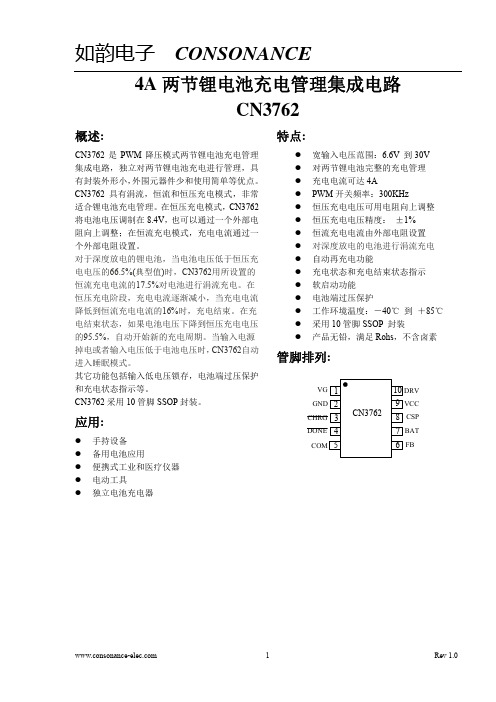
DSC-CN3762
参数
符号
测试条件
输入电压范围
VCC
低电压锁存阈值
UVLO
芯片工作电流 恒压充电电压
电流检测
流入 BAT 管脚电流
涓流充电阈值 涓流充电阈值迟滞 充电结束阈值 再充电阈值 过压阈值
IVCC VREG
VCS
IBAT1 IBAT2 VPRE HPRE Iterm VRE Vov
VBAT>VREG 恒压充电,FB 连接到 BAT VBAT>VPRE,VCSP-VBAT VBAT<VPRE,VCSP-VBAT 充电结束模式,VBAT=7.4V 睡眠模式,VBAT=7.4V BAT管脚电压上升 BAT管脚电压下降 充电电流下降 BAT管脚电压下降 BAT 管脚电压上升
超出以上所列的极限参数可能造成器件的永久损坏。以上给出的仅仅是极限范围,在这样的极限条件下工作, 器件的技术指标将得不到保证,长期在这种条件下还会影响器件的可靠性。
3
Rev 1.0
如韵电子 CONSONANCE
电气特性:
(VCC=15V,TA=-40℃ 到 85℃,除非另有注明)
调整恒压充电电压
如果在CN3762的FB管脚和BAT管脚之间接一个电阻,可以提高恒压充电电压,以抵消电池内阻和连线电阻的 电压降,使得电池充电更饱满,如图3所示。
输入电压 9 VIN
FB 6
CN3762
Rx
GND BAT 7
如果采用图3中的连接方式,那么恒压充电电压典型值VREG为:
的正极。同时,此管脚和CSP管脚测量电流检测电阻RCS两端的
电压,并将此电压信号反馈给CN3762进行电流调制。 充电电流检测正输入端。此管脚和BAT管脚测量电流检测电阻
ADM7172系列低噪声低电压LDO电路数据手册说明书

ADM7172ACPZ-1.8-R7 .ADM7172ACPZ-3.3-R7 .ADM7172ACPZ-5.0-R7 .ADM7172CP-EVALZ6.5 V, 2 A, Ultralow Noise, High PSRR,Fast Transient Response CMOS LDO Known Good Die ADM7172-KGDRev. A Document FeedbackInformation furnished by Analog Devices is believed to be accurate and reliable. However, noresponsibility is assumed by Analog Devices for its use, nor for any infringements of patents or other rights of third parties that may result from its use. Specifications subject to change without notice. No license is granted by implication or otherwise under any patent or patent rights of Analog Devices. T rademarks and registered trademarks are the property of their respective owners. One Technology Way, P.O. Box 9106, Norwood, M A 02062-9106, U.S.A. Tel: 781.329.4700 ©2015–2016 Analog Devices, Inc. All rights reserved. Technical Support FEATURESInput voltage range: 2.3 V to 6.5 VMaximum load current: 2 ALow noise: 5 µV rms independent of output voltage at100 Hz to 100 kHzFast transient response: 1.5 μs for 1 mA to 1.5 A load step 60 dB PSRR at 100 kHzLow dropout voltage: 172 mV at 2 A load, V OUT = 3 VInitial accuracy: −0.5% (minimum), +1% (maximum) Accuracy over line, load, and temperature: ±1.5% Quiescent current, I GND = 0.7 mA with no loadLow shutdown current: 0.25 μA at V IN = 5 VStable with small 4.7 µF ceramic output capacitor Adjustable and fixed output voltage options: 1.2 V to 5.0 V Adjustable output from 1.2 V to V IN − V DOPrecision enableAdjustable soft startAPPLICATIONSRegulation to noise sensitive applications: analog-to-digital converter (ADC) and digital-to-analog converter (DAC) circuits, precision amplifiers, phase-locked loops (PLLs)/ voltage controlled oscillators (VCOs), and clocking ICs Communications and infrastructureMedical and healthcareIndustrial and instrumentation GENERAL DESCRIPTIONThe ADM7172-KGD is a CMOS, low dropout linear regulator (LDO) that operates from 2.3 V to 6.5 V and provides up to 2 A of output current. This high output current LDO is ideal for regulation of high performance analog and mixed-signal circuits operating from 6 V down to 1.2 V rails. Using an advanced proprietary architecture, the device provides high power supply rejection and low noise and achieves excellent line and load transient response with just a small 4.7 µF ceramic output capacitor. Load transient response is typically 1.5 μs for a 1 mA to 1.5 A load step.The ADM7172-KGD is available in a 4.2 V fixed output voltage option. Additional voltages that are available by special order are1.3 V, 1.5 V, 1.8 V, 1.85 V,2.0 V, 2.2 V, 2.5 V, 2.7 V, 2.75 V, 2.8 V,2.85 V,3.0 V, 3.8 V, 3.3 V,4.2 V, 4.6 V,5.0 V, and an adjustable output option.Inrush current can be controlled by adjusting the start-up time via the soft start pin. The typical start-up time with a 1 nF soft start capacitor is 1.0 ms.The ADM7172-KGD regulator output noise is 5 μV rms, independent of the output voltage.Additional application and technical information can be found in the ADM7172 data sheet.ADM7172-KGDKnown Good DieRev. A | Page 2 of 7TABLE OF CONTENTSFeatures .............................................................................................. 1 Applications ....................................................................................... 1 General Description ......................................................................... 1 Revision History ............................................................................... 2 Specifications ..................................................................................... 3 Input and Output Capacitor, Recommended Specifications ....... 4 Absolute Maximum Ratings ............................................................5 ESD Caution...................................................................................5 Pad Configuration and Function Descriptions .............................6 Outline Dimensions ..........................................................................7 Die Specifications and Assembly Recommendations ..............7 Ordering Guide .. (7)REVISION HISTORY3/16—Rev. A to Rev. BChanges to General Description Section (1)9/15—Revision 0: Initial VersionKnown Good DieADM7172-KGDRev. A | Page 3 of 7SPECIFICATIONSV IN = (V OUT + 0.5 V) or 2.3 V (whichever is greater), EN = V IN , I LOAD = 10 mA, C IN = C OUT = 4.7 µF, T A = 25°C for typical specifications, T J = −40°C to +125°C for minimum/maximum specifications, unless otherwise noted. Table 1.ParameterSymbol Test Conditions/Comments Min Typ Max Unit INPUT VOLTAGE RANGE V IN 2.3 6.5 V LOAD CURRENTI LOAD2 A OPERATING SUPPLY CURRENT I GND I LOAD = 0 µA 0.7 2.0 mAI LOAD = 2 A4.8 8.7 mA SHUTDOWN CURRENTI GND-SD EN = GND, V IN = 5 V 0.25 3.8 µA OUTPUT VOLTAGE ACCURACYFixed Output Voltage Accuracy V OUT I LOAD = 10 mA, T J = 25°C−0.5 +1 %100 μA < I LOAD < 2 A, V IN = (V OUT + 0.5 V) to 6.5 V −1.5+1.5 % Adjustable Output Voltage Accuracy V SENSE I LOAD = 10 mA1.194 1.200 1.212 V10 mA < I LOAD < 2 A, V IN = (V OUT + 0.5 V) to 6.5 V 1.182 1.218 V REGULATIONLine ∆V OUT /∆V IN V IN = (V OUT + 0.5 V) to 6.5 V −0.1 +0.1 %/V Load∆V OUT /∆I LOAD I LOAD = 100 μA to 2 A0.1 0.3 %/A SENSE INPUT BIAS CURRENT SENSE I-BIAS 100 μA < I LOAD < 2 A, V IN = (V OUT + 0.5 V) to 6.5 V 1 nA DROPOUT VOLTAGE 1 V DROPOUT I LOAD = 500 mA, V OUT = 3 V 42 70 mV I LOAD = 1 A, V OUT = 3 V 84 135 mVI LOAD = 2 A, V OUT = 3 V172 270 mV OUTPUT NOISE OUT NOISE 10 Hz to 100 kHz, all fixed output voltages 6 µV rms100 Hz to 100 kHz, all fixed output voltages 5 µV rms Noise Spectral Density 100 Hz, all fixed output voltages 110 nV/√Hz 1 kHz, all fixed output voltages 40 nV/√Hz 10 kHz, all fixed output voltages 20 nV/√Hz100 kHz, all fixed output voltages12 nV/√Hz POWER SUPPLY REJECTION RATIO PSRR 100 kHz, V IN = 4.0 V, V OUT = 3 V, I LOAD = 1.5 A, C SS = 0 nF 60 dB 100 kHz, V IN = 3.5 V, V OUT = 3 V, I LOAD = 1.5 A, C SS = 0 nF 53 dB 100 kHz, V IN = 3.3 V, V OUT = 3 V, I LOAD = 1.5 A, C SS = 0 nF 42 dB 1 MHz, V IN = 4.0 V, V OUT = 3 V, I LOAD = 1.5 A, C SS = 0 nF 31 dB 1 MHz, V IN = 3.5 V, V OUT = 3 V, I LOAD = 1.5 A, C SS = 0 nF 30 dB1 MHz, V IN = 3.3 V, V OUT = 3 V, I LOAD = 1.5 A, C SS = 0 nF 20 dB TRANSIENT LOAD RESPONSE t TR-REC Time for output voltage to settle within ±V SETTLE from V DEV for a 1 mA to 1.5 A load step, load step rise time = 400 ns1.5 μs V DEV Output voltage deviation due to 1 mA to 1.5 A load step 35 mVV SETTLE Output voltage deviation after transient load response time (t TR-REC ) has passed, V OUT = 5 V, C OUT = 4.7 µF 0.1 % START-UP TIME 2 t START-UP V OUT = 5 V, C SS = 0 nF 380 µsV OUT = 5 V, C SS = 1 nF 1.0 ms SOFT START CURRENTI SS V IN = 5 V 0.5 1 1.5 µA CURRENT-LIMIT THRESHOLD 3 I LIMIT2.43.3 3.9 A V OUT PULL-DOWN RESISTANCE V OUT-PULL EN = 0 V, V OUT = 1 V 11 kΩ THERMAL SHUTDOWNThermal Shutdown Threshold TS SD T J rising 150 °C Thermal Shutdown Hysteresis TS SD-HYS 15 °C UNDERVOLTAGE THRESHOLDSInput Voltage Rising UVLO RISE 2.28 V Input Voltage Falling UVLO FALL 1.94 V HysteresisUVLO HYS200mVADM7172-KGDKnown Good DieRev. A | Page 4 of 7ParameterSymbol Test Conditions/Comments Min Typ Max Unit EN INPUT STANDBY2.3 V ≤ V IN ≤ 6.5 V EN Input Logic High EN STBY-HIGH 1.1 V EN Input Logic LowEN STBY-LOW 0.4 V EN Input Logic Hysteresis EN STBY-HYS80 mV EN INPUT PRECISION2.3 V ≤ V IN ≤ 6.5 V EN Input Logic High EN HIGH 1.11 1.2 1.27 V EN Input Logic LowEN LOW 1.01 1.1 1.16 V EN Input Logic Hysteresis EN HYS100 mV EN Input Leakage Current I EN-LKG EN = V IN or GND0.1 1.0 µA EN Input Delay TimeTI EN-DLYFrom EN rising from 0 V to V IN to 0.1 V × V OUT130μs1Dropout voltage is defined as the input to output voltage differential when the input voltage is set to the nominal output voltage. Dropout applies only for output voltages greater than 2.3 V. 2Start-up time is defined as the time between the rising edge of EN to VOUT being at 90% of the nominal value. 3Current-limit threshold is defined as the current at which the output voltage drops to 90% of the specified typical value. For example, the current limit for a 5.0 V output voltage is defined as the current that causes the output voltage to drop to 90% of 5.0 V, or 4.5 V.INPUT AND OUTPUT CAPACITOR, RECOMMENDED SPECIFICATIONSTable 2.ParameterSymbol Test Conditions/Comments Min Typ Max Unit MINIMUM INPUT AND OUTPUT CAPACITANCE 1 C MIN T A = −40°C to +125°C 3.3 µF CAPACITOR ESRR ESR T A = −40°C to +125°C 0.001 0.05 Ω1Ensure that the minimum input and output capacitance is greater than 3.3 μF over the full range of operating conditions. The full range of operating conditions in the application must be considered during device selection to ensure that the minimum capacitance specification is met. X7R and X5R type capacitors are recommended; Y5V and Z5U capacitors are not recommended for use with any LDO.Known Good DieADM7172-KGDRev. A | Page 5 of 7ABSOLUTE MAXIMUM RATINGSTable 3.Parameter RatingVIN to GND −0.3 V to +7 V VOUT to GND −0.3 V to V IN EN to GND −0.3 V to +7 V SS to GND −0.3 V to V IN SENSE to GND−0.3 V to +7 V Storage Temperature Range−65°C to +150°C Operating Junction Temperature Range −40°C to +125°C Soldering ConditionsJEDEC J-STD-020Stresses at or above those listed under Absolute Maximum Ratings may cause permanent damage to the product. This is a stress rating only; functional operation of the product at these or any other conditions above those indicated in the operational section of this specification is not implied. Operation beyond the maximum operating conditions for extended periods may affect product reliability.ADM7172-KGD Known Good DieFigure 1. Pad ConfigurationTable 4. Pad Function DescriptionsPad X-Axis (µm) Y-Axis (µm) Mnemonic Pad Type Description1A −392.275 +799.55 VOUT1A Triple Regulated Output Voltage, Triple Bond Pad.1B −392.275 +607.9 VOUT1B Triple Regulated Output Voltage, Triple Bond Pad.1C −392.275 +483.05 VOUT1C Triple Regulated Output Voltage, Triple Bond Pad.2A −392.275 +306.2 VOUT2A Triple Regulated Output Voltage, Triple Bond Pad.2B −392.275 +120.8 VOUT2B Triple Regulated Output Voltage, Triple Bond Pad.2C −392.275 −8.35 VOUT2C Triple Regulated Output Voltage, Triple Bond Pad.3 −392.25 −424.55 SENSE Single Sense Input.4 −392.25 −660.925 SS Single Soft Start.5 +400 −501.6 EN Single Regulator Enable.6A +399.8 −366.225 GNDA Double Ground, Double Bond Pad.6B +399.8 −271.225 GNDB Double Ground, Double Bond Pad.7A +246.6 −70.8 VIN1A Triple Regulator Input Supply, Triple Bond Pad.7B +246.6 +33.7 VIN1B Triple Regulator Input Supply, Triple Bond Pad.7C +246.6 +268.9 VIN1C Triple Regulator Input Supply, Triple Bond Pad.8A +246.6 +462.75 VIN2A Triple Regulator Input Supply, Triple Bond Pad.8B +246.6 +588.7 VIN2B Triple Regulator Input Supply, Triple Bond Pad.8C +246.6 +818.1 VIN2C Triple Regulator Input Supply, Triple Bond Pad.Rev. A | Page 6 of 7Known Good DieADM7172-KGDRev. A | Page 7 of 7OUTLINE DIMENSIONSFigure 2. 8-Pad Bare Die [CHIP](C-8-5)Dimensions shown in millimetersDIE SPECIFICATIONS AND ASSEMBLY RECOMMENDATIONSTable 5. Die SpecificationsParameterValueUnit Die Size (Maximum) 1020 × 1940 µm Bond Pad (Minimum) 70 × 70 µm Thickness203.2 µm Scribe Line Width80µm Bond Pad Composition AlCu (0.5%) %Passivation Type Nitride Not applicable Backside BiasGND Not applicableTable 6. Assembly RecommendationsAssembly Component Recommendation Die AttachAblestik 8290 Bonding Method1.2 mil goldORDERING GUIDEModelOutput Voltage (V) Temperature Range Package Description Package OptionADM7172-4.2-KGD-WP4.2−40°C to +125°C 8-Pad Bare Die [CHIP]C-8-508-21-2015-A×0.070©2015–2016 Analog Devices, Inc. All rights reserved. Trademarks and registered trademarks are the property of their respective owners. D13472-03/16(A)ADM7172ACPZ-1.8-R7 .ADM7172ACPZ-3.3-R7 .ADM7172ACPZ-5.0-R7 .ADM7172CP-EVALZ。
UVLO

低电压锁定(UVLO)
UVLO就是低电压锁定;低压关断. 欠压关断模式是当供电电压低于IC的开启门限电压时的一种保护模式。
欠压关断模式可保证IC在供电电压不足时不致于被损坏。
一个低电压锁定(UVLO)电路可确保IC在电池电压未达到安全操作电压前不会激活,UVLO的功能会展示滞后现象,以确保在电源供应上的噪音不会不慎导致系统故障。
uvlo的迟滞功能是防止电压在UVLO那一点的时候,出现振荡,所以加个迟滞.
为了更稳定的工作,某些DC/DC 转换器具有UVLO(欠压锁定)功能。
电源开启后,UVLO 功能使内部电路处于待机状态,直到DC/DC 转换器的输入电压(VIN)达到UVLO 电压,以此来减少消费电流并避免误操作。
晶电A3906低电压步进电机驱动器说明书

DescriptionDesigned for pulse width modulated (PWM) control of low voltage stepper motors, and single and dual DC motors, the A3906 is capable of output currents up to 1 A per channel and operating voltages from 2.5 to 9 V .The A3906 has an internal fixed off-time PWM timer that sets a peak current based on the selection of a current sense resistor. An overcurrent output flag is provided that notifies the user when the current in the motor winding reaches the peak current determined by the sense resistor. The fault output does not affect driver operation.The A 3906 is provided in a 20-contact, 4 mm × 4 mm, 0.75 mm nominal overall height QFN, with exposed pad for enhanced thermal dissipation. It is lead (Pb) free, with 100% matte tin leadframe plating.Applications include the following:▪ Digital still cameras (DSC)▪ Cell phone cameras ▪ USB powered devices ▪ Battery powered devicesFeatures and Benefits▪ 2.5 to 9 V operation▪ Internal PWM current limit control▪ Synchronous rectification for reduced power dissipation ▪ Peak current output flag ▪ Undervoltage lockout ▪ Low R DS(on) outputs ▪ Small package▪ Brake mode for DC motors ▪ Sleep function▪ Crossover-current protection ▪ Thermal shutdownLow V oltage Stepper and Single/Dual DC Motor DriverPackage: 20-contact QFN (suffix ES)Typical ApplicationsA3906Approximate sizeDual DC motor applicationStepper motor applicationAbsolute Maximum RatingsCharacteristicSymbol NotesRating Units Load Supply Voltage V BB 9.6V Logic Input Voltage Range V IN –0.3 to 7V Sense Voltage V SENSEx Continuous 0.5V Pulsed, t w < 1 μs1V Output CurrentI OUT May be limited by duty cycle, ambient temperature, and heat sinking. Under any set of conditions, do not exceed the specified current rating or a junction temperature of 150°C.Continuous 1A Peak, DC < 30% 1.5A Output Current in Paralleled OperationI OUT(par)Continuous 2A Peak, DC < 30%2.5A Operating Temperature Range T A Range S–20 to 85°C Junction Temperature T J(max)150°C Storage Temperature RangeT stg–40 to 150°CSelection GuidePart NumberPackingPackageA3906SESTR-T1500 pieces per 7-in. reel20-pin QFN with exposed thermal padThermal Characteristics may require derating at maximum conditions, see application informationCharacteristicSymbolTest Conditions*Value UnitsPackage Thermal ResistanceR θJA4-layer PCB based on JEDEC standard37ºC/W*Additional thermal information available on the Allegro website.Terminal List TableNumberName Function1CP2Charge pump capacitor terminal 22GND Ground3SLEEP Sleep logic input, active low 4IN1Control input 5IN2Control input6IN3Control input 7IN4Control input8FL1Current limit flag, bridge 19FL2Current limit flag bridge 210OUT2A DMOS full-bridge 2, output A11SENSE2Current sense resistor terminal, bridge 212OUT2B DMOS full-bridge 2, output B 13VBB Supply Voltage14OUT1B DMOS full-bridge 1, output B15SENSE1Current sense resistor terminal, bridge 116OUT1A DMOS full-bridge 1, output A 17VCP Reservoir capacitor terminal18CP3Charge pump capacitor terminal 319CP1Charge pump capacitor terminal 120CP4Charge pump capacitor terminal 4–PADExposed pad for enhanced thermal performancePAD1514131211123456789102019181716C P 4C P 1C P 3V C PO U T 1AI N 3I N 4F L 1F L 2O U T 2A SENSE1OUT1B VBB OUT2B SENSE2CP2GND SLEEPIN1IN2Pin-out DiagramFunctional Block DiagramELECTRICAL CHARACTERISTICS1,2 valid at T A = 25°C and V BB = 2.5 to 9 V, unless otherwise notedCharacteristics Symbol TestConditions Min.Typ.Max.UnitsOperating Voltage Range V BB 2.5–9VVBB Supply Current I BB I OUT = 0 mA, PWM = 50 kHz, Duty Cycle = 50% – 5 – mA I OUT = 0 mA, outputs disabled, V BB = 9.6 V– 3 – mA Sleep mode, V IN < 0.4 V– 150500nAOutput Resistance R DS(on)Source driver, I OUT = 400 mA , V BB = 3 V, T J = 25°C – 0.52 0.60ΩSource driver, I OUT = 400 mA , V BB = 3 V, T J = 85°C– 0.78– ΩSink driver, I OUT = 400 mA, V BB = 3 V, T J= 25°C – 0.62 0.74ΩSink driver, I OUT = 400 mA, V BB = 3 V, T J= 85°C – 0.93 – ΩCurrent Trip Sense Voltage V SENSE FLx falling edge160200240mV Clamp Diode Voltage V f I = 400 mA – – 1V Output Leakage Current I DSS Outputs,V OUT = 9 V –20 –20μA Control LogicLogic Input Voltage V IN(1) 2.0–5.5V V IN(0) ––0.8VLogic Input Current I IN(1)V IN = 5.5 V – <100 500nA I IN(0)V IN = 0.8 V – <–100 –500 nAInput Hysteresis V INhys –150–mV¯S¯¯L¯¯E¯¯E¯¯P¯ Input V SLEEP(0) ––0.4V V SLEEP(1) 2 – – VFault Output V FLx Flag asserted, I FLx = 1 mA – – 200mVFault Output Leakage Current I FLx V FLx = 5 V – – 1μAFault Output Timer t FLx Reset of PWM latch – 300 – μsBlank Time t BLANK 2.133.9μsFixed Off-Time t OFF –30–μsPropagation Delay Time t pd(on)Input high to source on, input low to source off 100235350ns t pd(off)Input low to sink off, input high to sink on 50100200nsProtection CircuitryCrossover Delay t COD 200425650ns VBB Undervoltage Lockout Threshold V BBUVLO V BB rising 2.2 2.31 2.45VVBB Undervoltage Lockout Hysteresis V BBUVHYS200 300 400mVThermal Shutdown Temperature T JTSD– 165 – °CThermal Shutdown Hysteresis T JTSDHYS –15–°C 1For input and output current specifications, negative current is defined as coming out of (sourcing) the specified device pin.2Specifications over the operating temperature range are assured by design and characterization.FLxNOTE:Timer resets after each reset of the PWM latch.Control LogicDC Motor OperationIN1 IN2 IN3 IN4 OUT1A OUT1B OUT2A OUT2B Function0 0 0 0 Off Off Off Off DisabledHighLow Forward1 0 1 0 HighLowHigh ReverseLow0 1 0 1 LowHighLow Brake1 1 1 1 LowLowLowStepper Motor OperationOUT2AOUT2B Function IN1 IN2 IN3 IN4 OUT1AOUT1B0 0 0 0 Off Off Off Off Disabled Disabled1 0 1 0 High Low High Low Full Step 1 ½ Step 1Step2Low –½High0 0 1 0 Off Off0 1 1 0 Low High High Low Full Step 2 ½ Step 34StepOff Off –½High0 1 0 0 Low0 1 0 1 Low High Low High Full Step 3 ½ Step 5Step6High –½0 0 0 1 Off Off Low1 0 0 1 High Low Low High Full Step 4 ½ Step 78Low Off Off –½1 0 0 0 HighStepDevice Operation The A3906 is a dual full-bridge low volt-age motor driver capable of operating one stepper motor, two DC motors, or one high current DC motor. MOSFET output stages substantially reduce the voltage drop and the power dissipation of the outputs of the A3906, compared to typical drivers with bipolar transistors.Output current can be regulated by pulse width modulating (PWM) the inputs. In addition supporting external PWM of the driver, the A3906 limits the peak current by internally PWMing the source driver when the current in the winding exceeds the peak current, which is determined by a sense resistor. A fault output notifies the user that peak current was reached. If internal current limiting is not needed, the sense pin should be shorted to ground.Internal circuit protection includes thermal shutdown with hyster-esis, undervoltage lockout, internal clamp diodes, and crossover current protection.The A3906 is designed for portable applications, providing a power-off low current sleep mode and an operating voltage of 2.5 to 9 V.External PWM Output current regulation can be achieved by pulse width modulating the inputs. Slow decay mode is selected by holding one input high while PWMing the other input. Hold-ing one input low and PWMing the other input results in fast decay. Refer to the Applications Information section for further information.Blanking This function blanks the output of the current sense comparator when the outputs are switched. The comparator output is blanked to prevent false overcurrent detections due to reverse recovery currents of the clamp diodes or to switching transients related to the capacitance of the load. The blank time, t BLANK, is approximately 3 μs.Sleep Mode An active-low control input used to minimize power consumption when the A3906 is not in use. This dis-ables much of the internal circuitry including the output drivers, internal regulator, and charge pump. A logic high allows normal operation. When coming out of sleep mode, wait 1.5 ms before issuing a command, to allow the internal regulator and charge pump to stabilize.Enable When all logic inputs are pulled to logic low, the outputs of the bridges are disabled. The charge pump and internal cir-cuitry continue to run when the outputs are disabled.Charge Pump (CP1, CP2, CP3, and CP4) When supply volt-ages are lower than 3.5 V, the two-stage charge pump triples the input voltage to a maximum of 7 V above the supply. The charge pump is used to create a supply voltage greater than V BB, to drive the source-side DMOS gates. For pumping purposes, a 0.1 μF ceramic capacitor should be connected between CP1 and CP2, and between CP3 and CP4. A 0.1 uF ceramic capacitor is required between VCP and VBB, to act as a reservoir to operate the high-side DMOS devices.Thermal Shutdown The A3906 will disable the outputs if the junction temperature reaches 165°C. When the junction tempera-ture drops 15°C, the outputs will be enabled.Brake Mode When driving DC motors, the A3906 goes into brake mode (turns on both sink drivers) when both of its inputs are high (IN1 and IN2, or IN3 and IN4). There is no protection during braking, so care must be taken to ensure that the peak current during braking does not exceed the absolute maximum current.Internal PWM Current Control Each full-bridge is controlled by a fixed off-time PWM current control circuit that limits the load current to a desired value, I TRIP. Initially, a diagonal pairof source and sink DMOS outputs are enabled and current flows through the motor winding and the current sense resistor, RSx. When the voltage across RSx equals the internal reference volt-age, the current sense comparator resets the PWM latch, which turns off the source driver.The maximum value of current limiting, I TRIP(max) , is set by the selection of the sense resistor, RSx, and is approximated by a transconductance function:I TRIP(max) = 0.2 / R S .It is critical to ensure the maximum rating on SENSEx pins (0.5 V) is not exceeded.Synchronous Rectification When a PWM off-cycle is trig-gered by an internal fixed off-time cycle, load current recirculates in slow decay SR mode. During slow decay, current recirculates through the sink-side FET and the sink-side body diode. The SR feature enables the sink-side FET, effectively shorting out the body diode. The sink driver is not enabled until the source driver is turned off and the crossover delay has expired. This feature helps lower the voltage drop during current recirculation, lower-ing power dissipation in the bridge.Overcurrent Output Flag When the peak current (set by the external resistor) is reached, the fault pin, FLx, is pulled low. When a reset of the PWM latch occurs, the fault timer begins. At each PWM latch reset, the timer is reset to zero. After approxi-mately 300 μs, if no peak current event was triggered, the timer expires and the fault is released. This ensures that during PWM current limiting, the fault pin remains in a fault state.Functional DescriptionApplications InformationVV V V IN1IN2IN3IN4+V BB R –V BB R I OUT1 ,I OUT2I OUT3 ,I OUT4+V BB R –V BB RGND GND+I REG0 A-I REGIN1,IN3IN2,IN4I OUTxV IN(1)V IN(1)External PWM If external PWM is used, the internal current control can either be disabled by shorting the SENSEx pin toground, or it can be used to limit the peak current to a value under the stall current to prevent motor heating. External PWM IN1 control is shown in the upper figure.Stepper Motor Control The A3906 also can be used to control a bipolar stepper motor. The control logic for stepper motor control is shown in the lower figure. The driver is capable of operating in full- and half-step modes.PWM current control in fast and slow decay modesStepper motor control in full- and half-step modesParallel Operation The A3906 can be paralleled for applica-tions that require higher output currents. In paralleled mode the driver can source 2 A continuous. The A3906 has two completely independent bridges with separate overcurrent latches. This allows the device to supply two separate loads, and as a result, when paralleled it is imperative that the internal current control is disabled by shorting the sense pins to ground.Because the overcurrent trip threshold is internally fixed at 0.2 V, the trace resistance must be kept small so the internal current latch is not triggered prematurely. With acceptable margin, the voltage drop across the trace resistance should be under 0.1 V. Ata peak current of 2.5 A, the trace resistance should be kept below40 mΩ to prevent false tripping of the overcurrent latch.Each bridge has some variation in propagation delay. During this time it is possible that one bridge will have to support the full load current for a very short period of time. Propagation delays are characterized and guard banded to protect the driver from damage during these events.Layout The printed circuit board should use a heavy ground-plane. For optimum electrical and thermal performance, theA3906 must be soldered directly onto the board. On the under-side of the A3906 package is an exposed pad, which provides a path for enhanced thermal dissipation. The thermal pad should be soldered directly to an exposed surface on the PCB. Thermal vias are used to transfer heat to other layers of the PCB.Grounding In order to minimize the effects of ground bounce and offset issues, it is important to have a low impedance single-point ground, known as a star ground, located very close to the device. By making the connection between the exposed thermal pad and the ground plane directly under the A3906, that areaDC Motor Operation (Parallel Bridge)IN1/IN3IN2/IN4OUT1A/2A OUT1B/2B Function 00OFF OFF Disabled 10H L FOR01L H REV11L L BRAKEPCB Layoutbecomes an ideal location for a star ground point. A low imped-ance ground will prevent ground bounce during high current operation and ensure that the supply voltage remains stable at the input terminal. The recommended PCB layout shown in the diagram below, illustrates how to create a star ground under the device, to serve both as low impedance ground point and thermal path.The two input capacitors should be placed in parallel, and as close to the device supply pins as possible. The ceramic capaci-tor should be closer to the pins than the bulk capacitor. This is necessary because the ceramic capacitor will be responsible for delivering the high frequency current components.Sense Pins The sense resistors, RS x , should have a very low impedance path to ground, because they must carry a large cur-rent while supporting very accurate voltage measurements by the current sense comparators. Long ground traces will cause additional voltage drops, adversely affecting the ability of the comparators to accurately measure the current in the windings. As shown in the layout below, the SENSE x pins have very short traces to the RS x resistors and very thick, low impedance traces directly to the star ground underneath the device. If possible, there should be no other components on the sense circuits.Note: When selecting a value for the sense resistors, be sure not to exceed the maximum voltage on the SENSE x pins of ±500 mV .ES Package, 20-Contact QFN with Exposed Thermal PadCopyright ©2008-2013, Allegro MicroSystems, LLCAllegro MicroSystems, LLC reserves the right to make, from time to time, such de p ar t ures from the detail spec i f i c a t ions as may be required to permit improvements in the per f or m ance, reliability, or manufacturability of its products. Before placing an order, the user is cautioned to verify that the information being relied upon is current.Allegro’s products are not to be used in life support devices or systems, if a failure of an Allegro product can reasonably be expected to cause the failure of that life support device or system, or to affect the safety or effectiveness of that device or system.The in f or m a t ion in c lud e d herein is believed to be ac c u r ate and reliable. How e v e r, Allegro MicroSystems, LLC assumes no re s pon s i b il i t y for its use; nor for any in f ringe m ent of patents or other rights of third parties which may result from its use.For the latest version of this document, visit our website:1A Terminal #1 mark areaCoplanarity includes exposed thermal pad and terminalsB Exposed thermal pad (reference only, terminal #1 identifier appearance at supplier discretion)For Reference Only(reference JEDEC MO-220WGGD)Dimensions in millimetersExact case and lead configuration at supplier discretion within limits shown C D CReference land pattern layout (reference IPC7351 QFN50P400X400X80-21BM)All pads a minimum of 0.20 mm from all adjacent pads; adjust as necessary to meet application process requirements and PCB layout tolerances; when mounting on a multilayer PCB, thermal vias at the exposed thermal pad land can improve thermal dissipation (reference EIA/JEDEC Standard JESD51-5)PCB Layout Reference View。
v uvlor欠压和v uvlo_hys滞回电压

v uvlo(欠压锁定)和v uvlo_hys(滞回电压)是电源管理电路中常见的两个重要参数,它们对于保护和稳定电源系统起着至关重要的作用。
本文将详细解释v uvlo和v uvlo_hys的概念、作用以及影响,帮助读者更好地理解和应用这两个参数。
1. v uvlo的概念和作用v uvlo是指输入电压低于设定值时,电源管理芯片会对其进行锁定,防止电源系统因输入电压过低而无法正常工作,保护整个系统免受损坏。
v uvlo的设定值一般由厂商根据实际电源系统需求进行设定,通常在数据手册中可以找到具体数值。
2. v uvlo_hys的概念和作用v uvlo_hys是指在输入电压低于设定值时,电源管理芯片会等待输入电压升高到一定值才会解除锁定状态,这个等待的电压差值即为v uvlo_hys。
v uvlo_hys的存在可以避免在输入电压波动较大的情况下,频繁锁定和解除锁定,保护整个系统。
3. v uvlo和v uvlo_hys的影响v uvlo和v uvlo_hys的设定值和大小都会对电源系统的稳定性、灵活性和响应速度产生影响。
过小的设定值和v uvlo_hys会使系统过于敏感,容易受到输入电压波动的影响而频繁锁定和解锁,降低系统的稳定性和可靠性;而过大的设定值和v uvlo_hys则会导致系统对输入电压变化的响应速度较慢,影响系统的动态性能和快速保护能力。
4. 如何合理选择v uvlo和v uvlo_hys的数值在选择v uvlo和v uvlo_hys的数值时,需要根据具体的电源系统需求和实际工作环境进行合理的设计和调整。
一般来说,厂商会在产品的数据手册中提供一些推荐的参数范围,用户可以根据自己的实际情况进行调整。
还可以通过仿真和实际测试来验证参数的合理性和稳定性。
通过本文的介绍,相信读者对v uvlo和v uvlo_hys这两个电源管理电路参数有了更清晰的理解和认识。
合理设置和调整这两个参数,可以有效保护电源系统免受输入电压低于设定值的影响,保障整个系统的稳定性和可靠性。
1.5A 低电压低静态电流LDO 稳压器

耗将导致器件的工作结温超过最大值 +150°C。结温持续停留在 150°C 以上将影响器件可靠性。
参数
符号
最小值 典型值 最大值 单位
条件
电压差特性
电压差
VIN-VOUT
—
电源正常 (Power Good)特性
PWRGD 输入电压工作范围
VPWRGD_VIN
1.0
1.2
PWRGD 阈值电压 (相对于 VOUT)
PWRGD 阈值迟滞电压 PWRGD 输出低电压
VPWRGD_TH
—
89
90
VPWRGD_HYS
应用
• 作为高速驱动芯片集的电源 • 网络背板卡 • 笔记本电脑 • 网络接口卡 • 掌上电脑 • 2.5V 至 1.XV 稳压器
Hale Waihona Puke 说明MCP1727 是一款 1.5A 低压差(LDO)线性稳压器,提 供高电流和低输出电压,并且封装小巧。 MCP1727 提 供固定 (或可调)输出电压,输出电压范围为 0.8V 至 5.0V。MCP1727 具有 1.5A 输出电流能力及低输出电压 能力,成为需要高电流的 1.8V 及以下输出电压 LDO 应 用的佳选。
电压稳定度
VOUT
VR - 2.5%
VR VR + 2.5%
V
注2
±0.5%
注 1: VIN 最小值必须满足两个条件,即:VIN ≥ 2.3V 且 VIN ≥ (VR + 2.5%) + VDROPOUT(MAX)。 2: 固定输出时, VR 为的标称稳压器输出电压。VR = 1.2V,1.8V 等。可调输出时, VR 为所需的设定点输出电压。 VR = VADJ * ((R1/R2)+1)。 3: TCVOUT = (VOUT-HIGH – VOUT-LOW) *106 / (VR * ∆Temperature)。VOUT-HIGH 为整个温度范围内测得的最高电压。 VOUT-LOW 为整个温度范围内测得的最低电压。 4: 负载稳定度的测量是在结温恒定时通过低占空比脉冲测试进行的。负载稳定度在负载从 1 mA 至最大规定输出电流范围 内进行了测试。
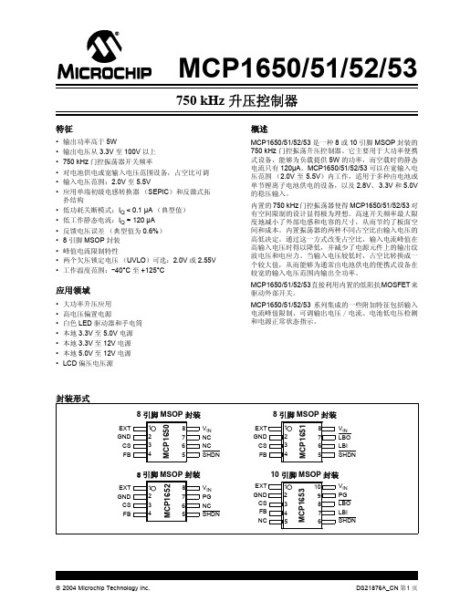
MCP1650
90.9 kΩ
COUT 10 µF 陶瓷电容
10 kΩ
DS21876A_CN 第 4 页
2004 Microchip Technology Inc.
MCP1650/51/52/53
1.0 电气特性
最大额定值 †
VIN 对 GND ........................................................... 6.0V CS,FB,LB,LBO,SHDN,PG,EXT............ GND – 0.3V 至
Q
EXT
DS21876A_CN 第 2 页
2004 Microchip Technology Inc.
MCP1650/51/52/53
MCP1651/2/3 结构框图
MCP1650/51/52/53
0&3᮴⡍ᗻ 0&3⬉∴Ԣ⬉य़Ẕ⌟ 0&3⬉⑤ℷᐌ⢊ᗕẔ⌟˄3*˅ 0&3⬉∴Ԣ⬉य़Ẕ⌟3*
中列出的数据可能超出确定的工作范围 (如:超出了正常的工作电压范围),因此不在担保范围。
注:除另有说明外, VIN = 3.3V, VOUT = 12V, CIN = 10 µF (X5R 或 X7R 陶瓷电容), COUT = 10 µF (X5R 或 X7R 电容), IOUT = 10 mA, L = 3.3 µH, SHDN > VIH, TA = +25°C。
参数
符号 最小值 典型值 最大值 单位
条件
关断时输入
逻辑高电平输入
VIN-HIGH
逻辑低电平输入ຫໍສະໝຸດ VIN-Low输入泄漏电流
ISHDN
电池低电压检测 (仅 MCP1652/MCP1653)
PoE关键技术
PoE关键技术一、概述:定义:PoE全称Power Over Ethernet,是指10BASE-T、100BASE-TX、1000BASE-T以太网网络供电,即数据线和电源线在同一根网线上传输,其可靠供电的距离最长为100米。
通过这种方式,可以有效的解决IP电话、无线AP、便携设备充电器、刷卡机、摄像头、数据采集等终端的集中式电源供电,对于这些终端而言不再需要考虑其室内电源系统布线的问题,在接入网络的同时就可以实现对设备的供电,极大的简化了综合布线的复杂性,降低了系统使用的成本。
在通用性方面,目前PoE供电有了统一的标准,只要遵循已经发布的IEEE802.3af和IEEE802.3at标准,就可以解决不同厂家设备之间的互连互通的问题。
POE供电的技术优势和拓展应用使用以太网线供电的优势是明显的:1. POE 只需要安装和支持一条电缆,简单而且节省空间,并且设备可随意移动。
2. 节约成本。
许多带电设备,例如视频监视摄像机等,都需要安装在难以部署AC电源的地方,POE 使其不再需要昂贵电源和安装电源所耗费的时间,节省了费用和时间。
3. 像数据传输一样,POE 可以通过使用简单网管协议(SNMP)来监督和控制该设备。
4. POE 供电端设备只会为需要供电的设备供电,只有连接了需要供电的设备,以太网电缆才会有电压存在,因而消除了线路上漏电的风险。
5. 一个单一的UPS 就可以提供相关所有设备在断电时的供电。
6. 用户可以自动、安全地在网络上混用原有设备和POE设备,这些设备能够与现有以太网电缆共存。
7. 使网络设备便于管理。
因为当远端设备与网络相连后,才能够远程控制、重配或重设。
8. 在无线局域网中,POE 可以简化射频测试任务,接入点能够被轻松地移动和接入。
二、PoE设备供电方式说明按照802.3af/at标准的定义,PoE供电系统包含两种设备PSE和PD,典型的设备应用组网图如下。
1. PSE(1)PSE设备的定义:PSE(power-sourcing equipment),主要是用来给其他设备进行供电的设备,(2)PSE设备的分类:其又可以分为两种,Midspan设备:PoE功能在交换机或其他网络设备外;Endpoint设备:PoE功能集成到交换机或其他网络设备内。
ROYER电路工作原理自激型推挽式直流变换器的电路原理-Read

2)欠压锁定 SG6841采用了欠压锁定比较器来保证输出级被驱动之前,集成电路已完全可用。欠压锁定回 路其实质是一个滞回比较器,以防止在通过它们各自的门限时产生错误的输出动作。它的开启电 压为16V,关闭电压为10V。在启动过程中,比较器反向输入端为16V,当VDD﹤16V时,比较器 输出为低电平,SG6841无法工作。当VDD升到16V时,欠压锁定器输出为高电平,SG6841正常 工作,同时MOS管导通,使比较器反向输入端为10V。当VDD下降至10V时,欠压锁定器的输出 回到低电平,整个电路停止工作。SG6841的7脚端设置了一个32V的齐纳二极管,保证内部电路 绝对工作在32V以下,以防电压过高损坏芯片。 3)输出部分 SG6841的8脚为输出脚,它是一个单图滕柱输出级,专门设计用来直接驱动功率MOSFET 的,具有降低热损耗、提高效率和增强可靠性的作用。在芯片内部有一18V的稳压管与Gate 端相连使输出电压钳位在18V,可保护MOSFET免被击穿。通过控制PWM脉冲的上升与下降 时间,可有效减少开关噪声,提高电源的EMI,并提供稳定的MOSFET管Gate极驱动。在 1.0nF负载时,它能提供高达±1.0A的峰值驱动电流和典型值为250ns的上升时间和50ns的下 降时间。还附加了一个内部电路,使得任何时候只要欠压锁定有效,输出就进入灌模式,这 个特性使外部下拉电阻不再需要。 4)电流取样比较器和脉冲调制锁存器 SG6841作为电流模式控制器工作,输出开关导通由振荡器开始振荡起始,当峰值电感电流到 达FB反馈端电平时终止。这样在逐周基础上误差信பைடு நூலகம்控制峰值电感电流。所用的电流取样比较器 -脉宽调制锁存配置确保在任何一定的振荡周期内,仅有一个单脉冲出现在输出端。 电感电流通过插入一个与输出开关Q901的源极串联的以地为参考的取样电阻Rs转换成电压。此 电压由电流取样输入端Pin6 Sense监视,并与来自Pin2 FB端电平相比较。通常取样电阻Rs为一 小电阻。在正常的工作条件下,峰值电感电流由管脚1上的电压控制,其中:Ipk =(VFB – 1.0V) /3RS
PoE交换机供电电压

PoE交换机供电电压PoE供电过程中只会输出三种供电电压,在检测阶段的供电电压时2。
5V-10V,在分级阶段的供电电压为15—20V,最后稳定在48V.只所以PoE供电电压会引起很多朋友的疑惑,原因在于市场上有很多非标准的PoE设备,这些PoE设备的输出电压各异,有12V、24V、48V等,尤其是有些设备的输出电压为48V,看起来好像和标准PoE一样,但实际差别很大,很具迷惑性。
实际上,对PoE供电电压的疑虑用一只万用表就可以搞定.拿电表测量PSE设备供电脚(1,2、3,6或者4,5、7,8)如果有48V或其它电压值稳定输出的是非标的(不做检测,48V或其它电压值直接供电);如果测量不出电压(2—10V跳动,在对PD端进行检测)则为标准POE(电表不是合法的PD,不会供电无电压).PSE直流12V/24V供电,直接到达PD供电—--—----—-——--------—-—---————-非标中的非标PSE直流48V供电,直接到达PD,降压供电-—-----------—-—————-—-—--——-非标POEPSE检测PD,分级,供电,降压供电,最后48V供电----—--—-—-——---—-—-—802.3af/at标准PoE丰润的PoE交换机系列均是标准的,支持IEEE802.3af/3at标准,在供电前会进行检测是否是标准的PoE受电设备,如果不是则不会供电,保证设备的安全。
POE以太网供电工作过程检测:首先PSE会发送一个测试电压给在网设备以探测受电设备中的一个24。
9kΩ共模电阻。
测试信号开始为2。
5V,然后提升到10V,这将有助于补偿Cat-5电缆自身阻抗带来的损失。
因为这种电缆最长可达100m.如果PSE检测到来自PD的适当阻抗特征(24.9kΩ),它便会继续提升电压.如果检测不到特征阻抗,PSE将不会为电缆加电。
受电设备电路中的齐纳二极管会保证系统其余部分不受测试信号的干扰.PD端设备分类:当检测到受电端设备PD之后,PSE将向PD施加15~20V的电压,并通过测量电流大小来确定PD的特定级别.如果除了探测到第一级的电阻外没发现其他分级电路,该设备被定义成零级别.在此阶段,PD的电源部分将被欠压锁定(UVLO)电路维持在无源状态,以便隔离开关级,直至特征和分级阶段完成。
M200a电路分析(电源、蓝牙、FM)

承受功率
500mW max
PLL loop filter and decoupling capacitor
CHG_PUMP(F1): pin for RF PLL loop filter 用来确定PLL带宽 MCG_CHG(B5):pin for reference PLL loop filter 低通滤波器对两电容要求很高(1%) VREFP_CAP(B1)/VREFN_CAP(B2):内部A/D转换器参考电压的退耦电容
◆PCM_0UT&PCM_IN接收或发送语音编 码信号。
❖ 具有JTAG口的芯片都有如下JTAG引脚定义: TCK——测试时钟输入; TDI——测试数据输入,数据通过TDI输入JTAG口; TDO——测试数据输出,数据通过TDO从JTAG口输出 TMS——测试模式选择,TMS用来设置JTAG口处于某 种特定的测试模式。 可选引脚:TRST——测试复位输入,低电平有效。 JTAG内部有一个状态机,称为TAP控制器。TAP控制器 的状态机通过TCK和TMS进行状态的改变,实现数据和 指令的输入。
PWRKEY:开关机信号,内部拉高到VBAT PWRBB:从微处理器来的开关机信号 SRCLKEN:VTCXO和VA使能
VMSEL:高电平对应Vm=2.8V,低电平对应Vm=1.8V VASEL:高电平对应VA由VTCXO使能,低电平对应VA由VCORE使能 BATDET:电池检测输入,低电平为电池已连接,内部接高表示电池未连接 BATUSE:电池类型选择,高电平为镍氢电池,低电平为锂电池,内部接低到地 LEDEN了:LED驱动输入 ,内部拉低到DGND VIBRATOREN:振动马达驱动输入 ,内部拉低到DGND
❖ 立体声音频输出 ❖ 很少的外部成分 ❖ 不需要手动调整部分 ❖ 10位IF记数器
L6599_中文资料
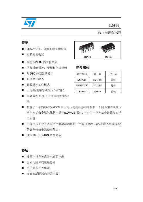
L6599高压谐振控制器特征50%占空比,谐振半桥变频控制 高精度振荡器高至500kHz 的工作频率 序号编码器件编码封 装包 装L6599D SO-16N 管装 L6599DTR SO-16N 卷带 L6599NDIP16管装两级过流保护:变频和停机闭锁 与PFC 控制器的接口 自锁禁止输入 轻载脉冲工作模式上电/断电顺序或欠压保护输入 单调输出电压上升为非线性软启动整合了一个能够承受600V 以上电压的高压浮动结构和一个同步驱动式高压横向双扩散金属氧化物半导体(LDMOS)器件,节省了一个外部快速恢复自举二极管用低电压下拉方式为两个栅驱动器提供一个输出电流0.3A 和灌入电流0.8A的典型峰值电流处理能力。
DIP-16,SO-16N 两种封装特征液晶电视和等离子电视的电源 台式电脑和初级服务器 电信设备开关电源 交直流适配器的开关电源框图目录1 驱动描述 . . . . . . . . . . . . . . . . . . . . . . . . . . . . . . . . . . . . . . . . . . . . . . . . . .42 引脚设置 . . . . . . . . . . . . . . . . . . . . . . . . . . . . . . . . . . . . . . . . . . . . . . . . . .52.1 引脚排列 . . . . . . . . . . . . . . . . . . . . . . . . . . . . . . . . . . . . . . . . . . . . . . . . . . . .52.2 引脚功能说明 . . . . . . . . . . . . . . . . . . . . . . . . . . . . . . . . . . . . . . . . . . . . . . . . 53 典型系统框图 . . . . . . . . . . . . . . . . . . . . . . . . . . . . . . . . . . . . . . . . . . . . . . 74 电气数据 . . . . . . . . . . . . . . . . . . . . . . . . . . . . . . . . . . . . . . . . . . . . . . . . . . 74.1 极限参数. . . . . . . . . . . . . . . . . . . . . . . . . . . . . . . . . . . . . . . . . . . . . . . . . . . . . .74.2 热相关数据. . . . . . . . . . . . . . . . . . . . . . . . . . . . . . . . . . . . . . . . . . . . . . . . . . . . .85 电气参数. . . . . . . . . . . . . . . . . . . . . . . . . . . . . . . . . . . . . . . . . . . . . . . . . . . 96 典型的电气性能. . . . . . . . . . . . . . . . . . . . . . . . . . . . . . . . . . . . . . . . . . . . . .127 应用资料. . . . . . . . . . . . . . . . . . . . . . . . . . . . . . . . . . . . . . . . . . . . . . . . . . . 157.1 振荡器. . . . . . . . . . . . . . . . . . . . . . . . . . . . . . . . . . . . . . . . . . . . . . . . . . . . . . .167.2 工作在空载或非常轻的负载状态. . . . . . . . . . . . . . . . . . . . . . . . . . . . . . . . . . .187.3 软启动. . . . . . . . . . . . . . . . . . . . . . . . . . . . . . . . . . . . . . . . . . . . . . . . . . . . . . . .217.4 电流检测,过流保护和过载保护 . . . . . . . . . . . . . . . . . . . . . . . . . . . . . . . . . 237.5 闭锁关机. . . . . . . . . . . . . . . . . . . . . . . . . . . . . . . . . . . . . . . . . . . . . . . . . . . . . .267.6 LINE检测功能. . . . . . . . . . . . . . . . . . . . . . . . . . . . . . . . . . . . . . . . . . . . . . . . . .277.7 自举部分 . . . . . . . . . . . . . . . . . . . . . . . . . . . . . . . . . . . . . . . . . . . . . . . . . . . .287.8 应用实例. . . . . . . . . . . . . . . . . . . . . . . . . . . . . . . . . . . . . . . . . . . . . . . . . . . . .298 封装外形尺寸 . . . . . . . . . . . . . . . . . . . . . . . . . . . . . . . . . . . . . . . . . . . . . . . . .9 修订记录 . . . . . . . . . . . . . . . . . . . . . . . . . . . . . . . . . . . . . . . . . . . . . . . . . . . .1 驱动描述L6599是一个用于谐振半桥拓扑电路的精确的双端控制器。
L6599芯片中文资料
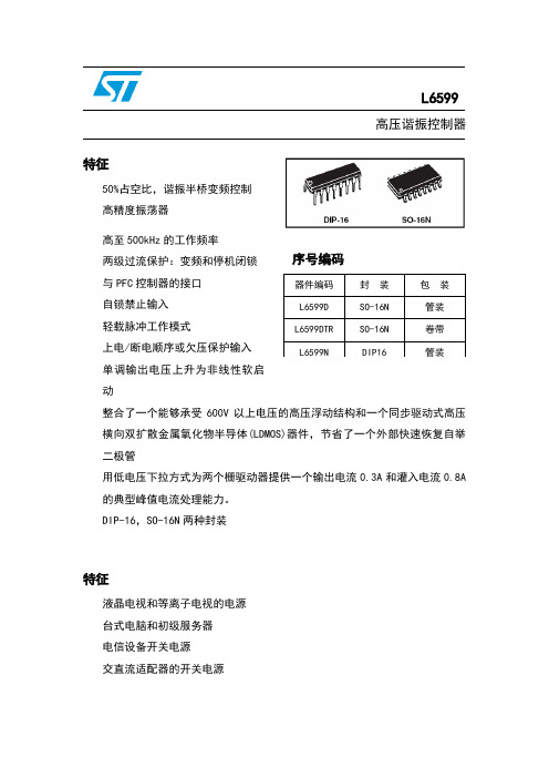
L6599高压谐振控制器特征50%占空比,谐振半桥变频控制 高精度振荡器高至500kHz 的工作频率 两级过流保护:变频和停机闭锁 与PFC 控制器的接口 自锁禁止输入 轻载脉冲工作模式上电/断电顺序或欠压保护输入 单调输出电压上升为非线性软启动整合了一个能够承受600V 以上电压的高压浮动结构和一个同步驱动式高压横向双扩散金属氧化物半导体(LDMOS)器件,节省了一个外部快速恢复自举二极管用低电压下拉方式为两个栅驱动器提供一个输出电流0.3A 和灌入电流0.8A 的典型峰值电流处理能力。
DIP-16,SO-16N 两种封装特征液晶电视和等离子电视的电源 台式电脑和初级服务器 电信设备开关电源 交直流适配器的开关电源序号编码器件编码 封 装 包 装 L6599D SO-16N 管装 L6599DTR SO-16N 卷带 L6599NDIP16管装框图目录1 驱动描述 . . . . . . . . . . . . . . . . . . . . . . . . . . . . . . . . . . . . . . . . . . . . . . . . . .42 引脚设置 . . . . . . . . . . . . . . . . . . . . . . . . . . . . . . . . . . . . . . . . . . . . . . . . . .5引脚排列 . . . . . . . . . . . . . . . . . . . . . . . . . . . . . . . . . . . . . . . . . . . . . . . . . . . .5引脚功能说明 . . . . . . . . . . . . . . . . . . . . . . . . . . . . . . . . . . . . . . . . . . . . . . . . 53 典型系统框图 . . . . . . . . . . . . . . . . . . . . . . . . . . . . . . . . . . . . . . . . . . . . . . 74 电气数据 . . . . . . . . . . . . . . . . . . . . . . . . . . . . . . . . . . . . . . . . . . . . . . . . . . 7极限参数 . . . . . . . . . . . . . . . . . . . . . . . . . . . . . . . . . . . . . . . . . . . . . . . . . . . . . .7热相关数据 . . . . . . . . . . . . . . . . . . . . . . . . . . . . . . . . . . . . . . . . . . . . . . . . . . . . .85 电气参数 . . . . . . . . . . . . . . . . . . . . . . . . . . . . . . . . . . . . . . . . . . . . . . . . . . . 96 典型的电气性能 . . . . . . . . . . . . . . . . . . . . . . . . . . . . . . . . . . . . . . . . . . . . . .127 应用资料 . . . . . . . . . . . . . . . . . . . . . . . . . . . . . . . . . . . . . . . . . . . . . . . . . . . 15振荡器 . . . . . . . . . . . . . . . . . . . . . . . . . . . . . . . . . . . . . . . . . . . . . . . . . . . . . . .16工作在空载或非常轻的负载状态 . . . . . . . . . . . . . . . . . . . . . . . . . . . . . . . . . . .18软启动 . . . . . . . . . . . . . . . . . . . . . . . . . . . . . . . . . . . . . . . . . . . . . . . . . . . . . . . .21电流检测,过流保护和过载保护 . . . . . . . . . . . . . . . . . . . . . . . . . . . . . . . . . 23闭锁关机 . . . . . . . . . . . . . . . . . . . . . . . . . . . . . . . . . . . . . . . . . . . . . . . . . . . . . .26LINE检测功能 . . . . . . . . . . . . . . . . . . . . . . . . . . . . . . . . . . . . . . . . . . . . . . . . . .27自举部分 . . . . . . . . . . . . . . . . . . . . . . . . . . . . . . . . . . . .. . . . . . . . . . . . . . . .28应用实例 . . . . . . . . . . . . . . . . . . . . . . . . . . . . . . . . . . . . . . . . . . . . . . . . . . . . .298 封装外形尺寸 . . . . . . . . . . . . . . . . . . . . . . . . . . . . . . . . . . . . . . . . . . . . . . . . .9 修订记录 . . . . . . . . . . . . . . . . . . . . . . . . . . . . . . . . . . . . . . . . . . . . . . . . . . . .1 驱动描述L6599是一个用于谐振半桥拓扑电路的精确的双端控制器。
AT1124_9110单通道低压H桥电机驱动芯片

AT1124/9110 包含单路 H 桥电机驱动电路。下图显示电路功能模块:
H-Bridge Circuitry
Bridge Control and Decay Modes
输入管脚 IN1 和 IN2 控制着输出管脚 OUT1 和 OUT2 的状态。下表显示了彼此间的逻辑关系。
9
管脚定义
TOP VIEW
AT1124/9110
单通道低压 H 桥电机驱动芯片
SOP-8
管脚列表
NAME 1124 9110
POWER AND GROUND
GND
6
5
GND
7
8
VM
1
2
VM
4
3
CONTROL
IN1
2
6
IN2
3
7
SLP
-
-
OUTPUT
OUT1
8
1
OUT2
5
4
1124LP
6 7 1 -
2 3 4
8 5
9110LP
5 8 3 -
6 7 2
1 4
Pin Description 器件地 电源
H桥输入1 H桥输入2
H桥输出1 H桥输出2
EXTERNAL COMPONENTS OR CONNECTIONS
所有地管脚需连到系统地。
电源,做好滤波,最小0.1uF电容到地,建议 10uF。 其中任意一个VM可选择NC 逻辑输入,控制H桥输出状态,内部下拉。
1
1.5
mA
0.5
10
uA
IN1,IN2 SLP(AT1124LP/9110LP)
0.7
FEELINGTECH--FP8012芯片--翻译
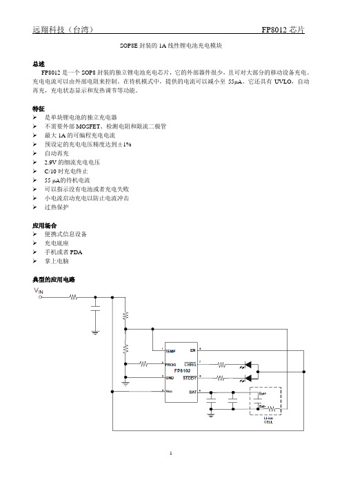
SOP8E封装的1A线性锂电池充电模块总述FP8012是一个SOP8封装的独立锂电池充电芯片,它的外部器件很少,且可对大部分的移动设备充电。
充电电流可以由外部电阻来控制。
在待机模式中,提供的电流可以减小至55μA。
它还具有UVLO,自动再充,充电状态显示和发热调节等功能。
特征是单块锂电池的独立充电器不需要外部MOSFET、检测电阻和限流二极管最大1A的可编程充电电流预设定的充电电压精度达到±1%自动再充2.9V的细流充电电压C/10时充电终止55 μA的待机电流可以指示没有电池或者充电失败小电流启动充电以防止电流冲击过热保护应用场合便携式信息设备充电底座手机或者PDA掌上电脑典型的应用电路功能模块图充电状态指示状态图引脚功能商标的含义无卤:产品不含卤的标示批号:晶片批号的最后两位数字例如:132386TB→86内部编码:内部的识别号每半个月:以半个月作为生产周期的标示例如:1月—→A(上半月),B(下半月)2月—→C(上半月),D(下半月)年:出产那年的最后一个数字订购信息绝对最大额定值推荐的应用环境直流电气特性待机模式,,V BAT上升,电流模式从高到低典型的应用特性(无特殊标明时,)功能描述操作FP8012最初是为单块锂电池充电而设计的线性电池充电器。
它采用恒定的电流或电压算法而且电流是可编程控制的。
充电电流根据外部的单块限流电阻来控制。
FP8012包含内部P通道的MOSFET和热控电路。
不需要限流二极管或者外部检测电阻。
因此,最基本的充电电路只需要两个外部组件。
此外,FP8012适用于由USB供电运行。
常规充电循环过程当Vcc引脚电压大于UVLO设定的阈值则开始充电。
如果BA T引脚的电压小于2.9V,则进入小电流充电模式,在这种模式下,FP8012输出的电流大约为设定电流的1/10进行充电直至充电完成。
当BAT引脚电压大于2.9V时,则输出以设定电流为准的恒流充电模式。
当BAT的引脚电压达到4.2V时,则进入恒压充电模式,此时充电电流开始减小,当充电电流减小到设定电流值的1/10时,充电循环终止。
Power over Ethernet (PoE)Powered Device (PD)Interface and Power
Power over Ethernet (PoE) Powered Device (PD)Interface and PowerConversionPower-Over-Ethernet (PoE)OverviewWhy PoE?–Deliver data + power to appliances over existing CAT-5 Ethernet cables–Governed by IEEE 802.3af requirements to deliver 15W max (13W load), 48V–Also IEEE802.3at (PoE Plus) 30W or greater capability–Both ends of cable need power management supportPSE:Ethernet Routers, Switchers, HubsPD:VoIP Phones, WLAN Access Points, Network Cameras, Security Systems美国国家半导体的以太网供电(PoE) 产品是为功率器件应用而设计的。
以太网供电的好处是:连接有关设备只需一条线缆——这既简化安装,又节省空间。
设备可以容易地移到局域网线缆所在的地方——对工作场所破坏最小。
S.E.L.V –安全特别低电压(最大60V DC),不会给用户或服务技术人员带来危险。
由于有了S.E.L.V.,以太网供电系统部署以及电缆布线不需要通过认证的电气技术人员,从而降低了安装成本。
PoE ArchitectureOption 1:Power can be sourced from the PSE through spare lines in the CAT-5 cable Option 2:Power can be sourced from the PSE through the data lines via data transformer center taps如图所示,以太网供电利用两个双绞数据对传输48V DC。
L6599引脚功能

L6599引脚功能1.Css:软启动端。
此脚与地(GND)间接一只电容Css,与4脚(RFmin)间接一只电阻Rss,用以确定软启动时的最高工作频率。
当Vcc(12脚)<UVLO (低电压闭锁),LINE(7脚)<1.25V或>6V,DIS(8脚)>1.85V(禁止端),ISEN(6脚)>1.5V,DELAY(2脚)>3.5V,以及当ISEN的电压超过0.8V或长时间超过0.75V时,芯片关闭,电容器Css通过芯片内部开关放电,以使再启动过程为软启动。
2.DELAY:过载电流延迟关断端。
此端对地并联接入电阻Rd和电容Cd各一只,设置过载电流的最长持续时间。
当ISEN脚的电压超过0.8V时,芯片内部将通过150uA的恒流源向Cd充电,当充电电压超过2.0V时,芯片输出将被关断,软启动电容Css上的电也被放掉。
电路关断之后,过流信号消失,芯片内部对Cd充电的3.5V电源被关断,Cd上的电通过Rd放掉,至电压低于0.3V 时,软启动开始。
这样,在过载或短路状态下,芯片周而复始地工作于间歇工作状态。
(Rd应不小于2V/150uA=13.3kΩ。
Rd越大,允许过流时间越短,关断时间越长。
)3.CF:定时电容。
对地间连接一只电容Cf,和4脚对地的RFmin配合可编程振荡器的开关频率。
4.RFmin:最低振荡频率设置。
4脚提供2V基准电压,并且,从4脚到地接一只电阻RFmin,用于设置最低振荡频率。
从4脚接一只电阻RFmax,通过反馈环路控制的光耦接地,将用于调整交换器的振荡频率。
RFmax是最高工作频率设置电阻。
4脚―1脚―GND间的RC网络实现软启动。
5.STBY:Standby,间歇工作模式门限(<1.25V)。
5脚受反馈电压控制,和内部的1.25V基准电压比较,如果5脚电压低于1.25V的基准电压,则芯片处于静止状态,并且只有较小的静态工作电流。
当5脚电压超过基准电压50mV 时,芯片重新开始工作。
昂宝 OB3370N 中文规格书
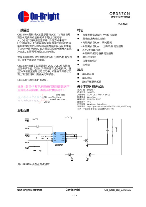
©On-Bright Electronics
Confidential -8-
OB_DOC_DS_3370NA0
封装数据
OB3370N 高性价比LED控制器
Symbol
A A1 A2 b c D E E1 e L θ
Dimensions In Millimeters
Min
Max
1.350
1.750
0.050
©On-Bright Electronics
Confidential -7-
OB_DOC_DS_3370NA0
OB3370N
高性价比LED控制器
VIN:10.8-13.2V LPWM:100%, 最大亮度; 30%最小亮度 ENA:禁用,0-0.8V; 启用,2-5V
图5 用于外部LPWM调光的OB3370N参考应用原理图
通过将BF/DMOD引脚短接到地,选择外部LPWM 突发调光模式。OB3370N接受外部LPWM信号到 DIM引脚,摆幅电压为0V,电平大于2V。LED亮度 由LPWM信号的占空比控制。突发频率等于LPWM 频率。
图3 占空与Dim电压的关系
功能
连接引脚 BF/DMOD DIM
比例
内部 Burst
电容
数字签名者:Wing Rises DN:cn=Wing Rises 日期:2018.04.08 01:18:52 +08'00'
典型应用
产品规格
特征
电压型脉宽调制(PWM)控制器 灵活的调光模式控制:
| 内部突发(Burst)调光控制 | 外部突发(Burst)(LPWM)调光控制 0-2V直流电压或
0.250
1.250
- 1、下载文档前请自行甄别文档内容的完整性,平台不提供额外的编辑、内容补充、找答案等附加服务。
- 2、"仅部分预览"的文档,不可在线预览部分如存在完整性等问题,可反馈申请退款(可完整预览的文档不适用该条件!)。
- 3、如文档侵犯您的权益,请联系客服反馈,我们会尽快为您处理(人工客服工作时间:9:00-18:30)。
que:您好,看了您写的文章使得我对UVIO有了一个初步的了解,目前我在做电源方面的设计,使用TI的LMZ31710芯片,我看到它的芯片手册上在讲到UVIO引脚,里面提到了一个参数叫做 Hysteresis 单位是mV,不知道是什么意义?
da:Hysteresis: 磁滞 这个参数就是一个芯片恢复正常状态,也就是退出UVLO状态的电压差值,比如uvlo是2.7V ,Hysteresis 为100mv,那么电压升高到UVLO + Hysteresis 也就是2.8
低电压锁定(UVLO)
UVLO就是低电压锁定; 低压关断. 欠压关断模式是当供电电压低于IC损坏。一个低电压锁定(UVLO)电路可确保IC在电池电压未达到安全操作电压前不会激活,UVLO的功能会展示滞后现象,以确保在电源供应上的噪音不会不慎导致系统故障。
uvlo的迟滞功能是防止电压在UVLO那一点的时候,出现振荡,所以加个迟滞.
为了更稳定的工作,某些 DC/DC 转换器具有 UVLO(欠压锁定)功能。电源开启后,UVLO 功能使内部电路处于待机状态,直到DC/DC 转换器的输入电压(VIN)达到 UVLO 电压,以此来减少消费电流并避免误操作。
