bgp综合实例
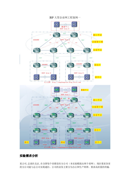
BGP大型企业网工程案例一
10.业务位(2 位)地区位(6 位).子业务位(8 位).子网位 主机位
业务位 0 1 2 3
//为区域 1 路由汇总
default-information originate always metric 1000 //下发缺省路由 int f1/0 ip ospf network point-to-point //修改网络类型为点对点平面间开销为 400 ip ospf cost 400 int f2/0 ip ospf network point-to-point
10.67.0.0/16
10.131.0.0/16
数据中心链 路及网管 数据中心生 产业务 数据中心办 公业务
湖南
10.4.0.0/16 10.68.0.0/16 10.132.0.0/16
湖北链路 及网管 湖北生产 业务 湖北办公 业务 湖南链路 及网管 湖南生产 业务 湖南办公 业务
IP 地址分配表 loopback 0 RT1 loopback 0 RT2 loopback 0 RT3 loopback 0 RT4 loopback 0 RT5 loopback 0 RT6 loopback 0 SW7 loopback 0 SW8 loopback 0 RT9 loopback 0 RT10 loopback 0 SW11 loopback 0 SW12 loopback 0 RT13 loopback 0 RT14 loopback 0 SW15 loopback 0 SW16 VLAN16 生产 SW7 VLAN17 办公 SW7 VLAN16 生产 SW8 VLAN17 办公 SW8 VLAN16 生产 SW11 VLAN17 办公 SW11 VLAN16 生产 SW12 VLAN17 办公 SW12 VLAN16 生产 SW15 VLAN17 办公 SW15 VLAN16 生产 SW16 VLAN17 办公 SW16 RT9-RT10 RT9
BGP综合实验
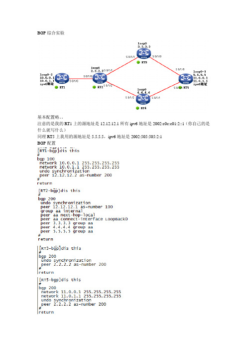
BGP综合实验基本配置略。
注意的是我的RT1上的源地址是12.12.12.1所有ipv6地址是2002:c0c:c01:2::1(你自己的是什么就写什么)同理RT5上我用的源地址是5.5.5.5,ipv6地址是2002:505:505:2:1BGP配置Ospf配置略。
加入验证增加安全注意把12.12.12.0网段发布下不然IPV6隧道路由你还得引入什么的6TO4隧道RT1(注意先开启ipv6功能)ipv6 route-static 2002:: 16 Tunnel 0两边加入静态路由可以看到没有问题选路问题选路有多种方法我这里修改的通过BGP修改下一跳,别的方法我也迷糊,- -!首先我们看RT2的路由表,我只是截取了部分我们想看的太多我们先做RT1到RT5的路由选路,原理是做一个route-policy的过滤器,在第一个节点匹配10.0.0.1和11.0.0.1这个网段的或者这个IP,动作是修改下一跳为3.3.3.3(这个3.3.3.3可以让你断一条链路的情况下也能互通)我这个是为了方便在这RT5的一边做的同样匹配10.0.1.1和11.0.1.1这个,动作是修改下一跳为4.4.4.4应用到import和export两个方向上还需要注意的是11.0.0.1和11.0.1.1这两条路由产生了黑洞,黑洞在RT3和RT4上我没还需要在RT3和RT4上加入静态路由解决黑洞[RT3]ip route-static 11.0.0.0 24 5.5.5.5[RT4]ip route-static 11.0.1.0 24 5.5.5.5这样我们再看路由表RT2上RT5上OK了命令简单想费劲RT1上测试RT5上来回路径一致。
【CCNP】BGP路由汇聚配置案例
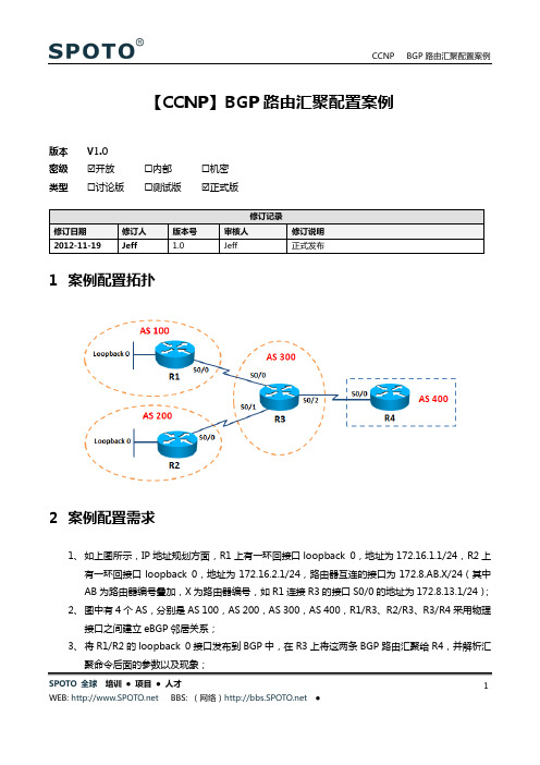
【CCNP】BGP路由汇聚配置案例版本V1.0密级☑开放☐内部☐机密类型☐讨论版☐测试版☑正式版1案例配置拓扑2案例配置需求1、如上图所示,IP地址规划方面,R1上有一环回接口loopback 0,地址为172.16.1.1/24,R2上有一环回接口loopback 0,地址为172.16.2.1/24,路由器互连的接口为172.8.AB.X/24(其中AB为路由器编号叠加,X为路由器编号,如R1连接R3的接口S0/0的地址为172.8.13.1/24);2、图中有4个AS,分别是AS 100,AS 200,AS 300,AS 400,R1/R3、R2/R3、R3/R4采用物理接口之间建立eBGP邻居关系;3、将R1/R2的loopback 0接口发布到BGP中,在R3上将这两条BGP路由汇聚给R4,并解析汇SPOTO 全球培训●项目●人才 1SPOTO 全球 培训 ● 项目 ● 人才2 3 案例配置思路1、 R1上的关键配置:router bgp 100no synchronizationbgp log-neighbor-changesnetwork 172.16.1.0 mask 255.255.255.0neighbor 172.8.13.3 remote-as 300no auto-summary2、 R2上的关键配置:router bgp 200no synchronizationbgp log-neighbor-changesnetwork 172.16.2.0 mask 255.255.255.0neighbor 172.8.23.3 remote-as 300no auto-summary3、 R3上的关键配置:router bgp 300no synchronizationbgp log-neighbor-changesaggregate-address 172.16.0.0 255.255.252.0 /BGP 路由汇聚,汇总命令后的参数将在“案例检验结果出分析”/ 雏鹰论坛CCNPneighbor 172.8.13.1 remote-as 100neighbor 172.8.23.2 remote-as 200neighbor 172.8.34.4 remote-as 400no auto-summary4、 R4上的关键配置:router bgp 400no synchronizationbgp log-neighbor-changesneighbor 172.8.34.3 remote-as 300no auto-summarySPOTO 全球 培训 ● 项目 ● 人才3 4 案例检验结果1、 配置汇总命令aggregate-address 172.16.0.0 255.255.252.0后,在R3和R4关于汇总路由和细路由的显示情况:R3#show ip bgpBGP table version is 11, local router ID is 172.8.34.3Status codes: s suppressed, d damped, h history, * valid, > best, i - internal,r RIB-failure, S StaleOrigin codes: i - IGP , e - EGP , ? - incompleteNetwork Next Hop Metric LocPrf Weight Path*> 172.16.0.0/22 0.0.0.0 32768 i*> 172.16.1.0/24 172.8.13.1 0 0 100 i*> 172.16.2.0/24 172.8.23.2 0 0 200 i/从R1/R2学习到的两条BGP 路由汇总为/22的路由/R4#show ip bgpBGP table version is 11, local router ID is 172.8.34.4Status codes: s suppressed, d damped, h history, * valid, > best, i - internal,r RIB-failure, S StaleOrigin codes: i - IGP , e - EGP , ? - incompleteNetwork Next Hop Metric LocPrf Weight Path*> 172.16.0.0/22 172.8.34.3 0 0 300 i*> 172.16.1.0/24 172.8.34.3 0 300 100 i*> 172.16.2.0/24 172.8.34.3 0 300 200 i/从R3学习到了/22的汇总路由,同时也学习了两条细路由,在R3上汇总,所以汇总路由只包含R3所在的AS 300,路由源的AS 丢失/ 雏鹰论坛CCNPR4#show ip bgp 172.16.0.0 255.255.252.0BGP routing table entry for 172.16.0.0/22, version 11Paths: (1 available, best #1, table Default-IP-Routing-Table)Not advertised to any peerSPOTO 全球 培训 ● 项目 ● 人才4 300, (aggregated by 300 172.8.34.3)172.8.34.3 from 172.8.34.3 (172.8.34.3)Origin IGP , metric 0, localpref 100, valid, external, atomic-aggregate , best/atomic-aggregate 属性表明发生了路由属性的丢失,aggregator 属性表明在哪里丢失属性,从上面的show 命令可以看出,R3在AS 300执行了路由汇总/2、 配置汇总命令aggregate-address 172.16.0.0 255.255.252.0 as-set ,加上as-set 参数后,在R3和R4显示的关于汇总路由和细路由的情况:R3#show ip bgpBGP table version is 12, local router ID is 172.8.34.3Status codes: s suppressed, d damped, h history, * valid, > best, i - internal,r RIB-failure, S StaleOrigin codes: i - IGP , e - EGP , ? - incompleteNetwork Next Hop Metric LocPrf Weight Path*> 172.16.0.0/22 0.0.0.0 100 32768 {100,200} i*> 172.16.1.0/24 172.8.13.1 0 0 100 i*> 172.16.2.0/24 172.8.23.2 0 0 200 iR4#show ip bgpBGP table version is 12, local router ID is 172.8.34.4Status codes: s suppressed, d damped, h history, * valid, > best, i - internal,r RIB-failure, S StaleOrigin codes: i - IGP , e - EGP , ? - incompleteNetwork Next Hop Metric LocPrf Weight Path*> 172.16.0.0/22 172.8.34.3 0 0 300 {100,200} i*> 172.16.1.0/24 172.8.34.3 0 300 100 i*> 172.16.2.0/24 172.8.34.3 0 300 200 i/汇总路由的AS PATH 列表中携带上了路由源的AS {100,200},不过在做路径选择时,花括号{}内的AS 只能当一个AS 计算/ 雏鹰论坛CCNPR4#show ip bg 172.16.0.0 255.255.252.0BGP routing table entry for 172.16.0.0/22, version 12Paths: (1 available, best #1, table Default-IP-Routing-Table)SPOTO 全球 培训 ● 项目 ● 人才5 Flag: 0x820Not advertised to any peer300 {100,200}, (aggregated by 300 172.8.34.3)172.8.34.3 from 172.8.34.3 (172.8.34.3)Origin IGP , metric 0, localpref 100, valid, external, best/在R3的汇聚命令后加上了AS-SET 参数,则AS 属性不会出现丢失的情况,那么在这里atomic-aggregate 属性就没有了,由此可以看出,AS-SET 和atomic-aggregate 属性互斥,AS-SET 参数是将所有细路由的属性复制到汇总路由/3、 配置汇总命令aggregate-address 172.16.0.0 255.255.252.0 as-set summar-only ,再加上summary-only 参数后,在R3和R4显示的关于汇总路由和细路由的情况:R3#show ip bgpBGP table version is 14, local router ID is 172.8.34.3Status codes: s suppressed, d damped, h history, * valid, > best, i - internal,r RIB-failure, S StaleOrigin codes: i - IGP , e - EGP , ? - incompleteNetwork Next Hop Metric LocPrf Weight Path*> 172.16.0.0/22 0.0.0.0 100 32768 {100,200} is > 172.16.1.0/24 172.8.13.1 0 0 100 is > 172.16.2.0/24 172.8.23.2 0 0 200 i/添加了summary-only 参数后,细路由前面出现了“s ”标志,表明被抑制掉了,抑制的路由不会发送给它的邻居/R4#show ip bgpBGP table version is 14, local router ID is 172.8.34.4Status codes: s suppressed, d damped, h history, * valid, > best, i - internal,r RIB-failure, S StaleOrigin codes: i - IGP , e - EGP , ? - incompleteNetwork Next Hop Metric LocPrf Weight Path*> 172.16.0.0/22 172.8.34.3 0 0 300 {100,200} i/只存在汇总路由/4、 抑制单条细路由的汇总命令:SPOTO 全球 培训 ● 项目 ● 人才6 ip prefix-list supp seq 5 permit 172.16.1.0/24!route-map supp permit 10match ip address prefix-list supp! aggregate-address 172.16.0.0 255.255.252.0 as-set suppress-map suppR3#show ip bgpBGP table version is 5, local router ID is 172.8.34.3Status codes: s suppressed, d damped, h history, * valid, > best, i - internal,r RIB-failure, S StaleOrigin codes: i - IGP , e - EGP , ? - incompleteNetwork Next Hop Metric LocPrf Weight Path*> 172.16.0.0/22 0.0.0.0 100 32768 {100,200} is > 172.16.1.0/24 172.8.13.1 0 0 100 i*> 172.16.2.0/24 172.8.23.2 0 0 200 i/只有172.16.1.0/24被抑制,此路由不会发送给它的BGP 邻居/R4#show ip bgpBGP table version is 19, local router ID is 172.8.34.4Status codes: s suppressed, d damped, h history, * valid, > best, i - internal,r RIB-failure, S StaleOrigin codes: i - IGP , e - EGP , ? - incompleteNetwork Next Hop Metric LocPrf Weight Path*> 172.16.0.0/22 172.8.34.3 0 0 300 {100,200} i*> 172.16.2.0/24 172.8.34.3 0 300 200 i/没有收到172.16.1.0/24的路由/5、 查看R3的ip 路由表:R3# sh ip routeCodes: C - connected, S - static, R - RIP , M - mobile, B - BGPD - EIGRP , EX - EIGRP external, O - OSPF, IA - OSPF inter areaN1 - OSPF NSSA external type 1, N2 - OSPF NSSA external type 2SPOTO 全球 培训 ● 项目 ● 人才7 E1 - OSPF external type 1, E2 - OSPF external type 2i - IS-IS, su - IS-IS summary, L1 - IS-IS level-1, L2 - IS-IS level-2ia - IS-IS inter area, * - candidate default, U - per-user static routeo - ODR, P - periodic downloaded static routeGateway of last resort is not set172.8.0.0/24 is subnetted, 3 subnetsC 172.8.34.0 is directly connected, Serial0/2C 172.8.13.0 is directly connected, Serial0/0C 172.8.23.0 is directly connected, Serial0/1172.16.0.0/16 is variably subnetted, 3 subnets, 2 masksB 172.16.0.0/22 [200/0] via 0.0.0.0, 00:00:04, Null0 /汇总路由指向Null0/B 172.16.1.0/24 [20/0] via 172.8.13.1, 00:00:36 雏鹰论坛CCNPB 172.16.2.0/24 [20/0] via 172.8.23.2, 00:45:055 案例配置文件6 案例总结及其它1、 BGP 汇总命令aggregate-address 后面的参数比较丰富,大家可以根据需要添加合适的参数;SPOTO 全球 培训 ● 项目 ● 人才8SPOTO 全球 培训 ● 项目 ● 人才9/advertise-map 和as-set 结合,表示路由器根据某些细路由的属性复制到汇总路由,advertise-map 后跟的是route-map/ip prefix-list supp seq 5 permit 172.16.1.0/24!route-map supp permit 10match ip address prefix-list supp!router bgp 300aggregate-address 172.16.0.0 255.255.252.0 as-set advertise-map supp效果:R3#show ip bgpBGP table version is 19, local router ID is 172.8.34.3Status codes: s suppressed, d damped, h history, * valid, > best, i - internal,r RIB-failure, S StaleOrigin codes: i - IGP , e - EGP , ? - incompleteNetwork Next Hop Metric LocPrf Weight Path*> 172.16.0.0/22 0.0.0.0 100 32768 100 i*> 172.16.1.0/24 172.8.13.1 0 0 100 i*> 172.16.2.0/24 172.8.23.2 0 0 200 iR3#show ip bgp 172.16.1.0BGP routing table entry for 172.16.1.0/24, version 2SPOTO 全球 培训 ● 项目 ● 人才10 Paths: (1 available, best #1, table Default-IP-Routing-Table)Advertised to update-groups:1100172.8.13.1 from 172.8.13.1 (172.16.1.1)Origin IGP , metric 0, localpref 100, valid, external, bestR3#show ip bgp 172.16.0.0BGP routing table entry for 172.16.0.0/22, version 18Paths: (1 available, best #1, table Default-IP-Routing-Table)Advertised to update-groups:1100, (aggregated by 300 172.8.34.3)0.0.0.0 from 0.0.0.0 (172.8.34.3)Origin IGP , localpref 100, weight 32768, valid, aggregated, local, atomic-aggregate, best/按照上面的配置,汇总路由复制了细路由172.16.1.0/24的BGP 属性/R4#show ip bgpBGP table version is 31, local router ID is 172.8.34.4Status codes: s suppressed, d damped, h history, * valid, > best, i - internal,r RIB-failure, S StaleOrigin codes: i - IGP , e - EGP , ? - incompleteNetwork Next Hop Metric LocPrf Weight Path*> 172.16.0.0/22 172.8.34.3 0 0 300 100 i*> 172.16.1.0/24 172.8.34.3 0 300 100 i*> 172.16.2.0/24 172.8.34.3 0 300 200 i/attribute-map 和as-set 结合,手动设置汇总路由的属性,attribute-map 后跟的是route-map/ route-map supp permit 10set origin incomplete!router bgp 300aggregate-address 172.16.0.0 255.255.252.0 as-set attribute-map suppCCNP BGP路由汇聚配置案例SPOTO 全球培训●项目●人才WEB: BBS: (网络) ●11效果:R3#show ip bgpBGP table version is 5, local router ID is 172.8.34.3Status codes: s suppressed, d damped, h history, * valid, > best, i - internal,r RIB-failure, S StaleOrigin codes: i - IGP, e - EGP, ? - incompleteNetwork Next Hop Metric LocPrf Weight Path *> 172.16.0.0/22 0.0.0.0 100 32768 {100,200} ?*> 172.16.1.0/24 172.8.13.1 0 0 100 i*> 172.16.2.0/24 172.8.23.2 0 0 200 i/采用attribute-map手动设定汇总路由的属性/R4#show ip bgpBGP table version is 51, local router ID is 172.8.34.4Status codes: s suppressed, d damped, h history, * valid, > best, i - internal,r RIB-failure, S StaleOrigin codes: i - IGP, e - EGP, ? - incompleteNetwork Next Hop Metric LocPrf Weight Path *> 172.16.0.0/22 172.8.34.3 0 0 300 {100,200} ?*> 172.16.1.0/24 172.8.34.3 0 300 100 i*> 172.16.2.0/24 172.8.34.3 0 300 200 i2、参见欢迎来雏鹰论坛参与讨论。
CCNP之BGP试验案例[优质文档]
![CCNP之BGP试验案例[优质文档]](https://img.taocdn.com/s3/m/8a4c44542f3f5727a5e9856a561252d380eb20c3.png)
CCNP之BGP实验案例实验需求:1、每一台路由器都起一个/32的回环地址,用来建立BGP邻居关系2、大型企业内部起OSPF协议,ISP B内部也起OSPF协议,企业A分别和ISP B和ISP C建立BGP邻接关系,以用来透传互联网上的条目3、要求ISP C学到挂在ISP B的服务器条目尽可能少4、要求ISP C前往ISP B那些服务器是通过R3和R5之间的高带宽链路,为了充分利用带宽,要求ISP B访问ISP C上的服务器是走的R4和R6之间的低带宽链路,这些配置都需要在大型企业上完成5、要求ISP和企业之间建立的BGP邻接是安全的6、完成配置之后,确信网络中每一台设备都学到了服务器对应的BGP条目实验拓扑图:实验步骤:1、在大型企业A和ISP B内部起OSPF协议R2:R2(config)#router ospf 1R2(config-router)#net 2.2.2.2 0.0.0.0 a 0R2(config-router)#net 23.23.23.23 0.0.0.0 a 0R2(config-router)#net 24.24.24.24 0.0.0.0 a 0R3:R3(config)#router ospf 1R3(config-router)#net 3.3.3.3 0.0.0.0 a 0R3(config-router)#net 23.23.23.1 0.0.0.0 a 0R4:R4(config)#router ospf 1R4(config-router)#net 4.4.4.4 0.0.0.0 a 0R4(config-router)#net 24.24.24.1 0.0.0.0 a 0R5:R5(config)#router ospf 1R5(config-router)#net 5.5.5.5 0.0.0.0 a 0R5(config-router)#net 57.57.57.2 0.0.0.0 a 0R6:R6(config)#router ospf 1R6(config-router)#net 6.6.6.6 0.0.0.0 a 0R6(config-router)#net 67.67.67.2 0.0.0.0 a 0R7:R7(config)#router ospf 1R7(config-router)#net 7.7.7.7 0.0.0.0 a 0R7(config-router)#net 57.57.57.1 0.0.0.0 a 0R7(config-router)#net 67.67.67.1 0.0.0.0 a 02、全网启用BGP协议由于ebgp建立在TCP连接的基础上,所以需要配置静态路由。
华为BGP配置实例

h - history, i - internal, s - suppressed, S - Stale
Origin : i - IGP, e - EGP, ? - incomplete Network NextHop MED LocPrf PrefVal Path/Ogn
*> 8.1.1.0/24
用peer connect-interface命令将Loopback接口配置为BGP连接的源接口。 Router C的Loopback接口路由可达。
# 配置Router B。
<RouterB> system-view [RouterB] bgp 65009 [RouterB-bgp] router-id 2.2.2.2 [RouterB-bgp] peer 3.3.3.3 as-number 65009
3.1.1.0/24的路由。
# 配置Router B。 [RouterB] bgp 65009 [RouterB-bgp] import-route direct # 显示Router A的BGP路由表。
[RouterA] display bgp routing-table
Total Number of Routes: 4 BGP Local router ID is 1.1.1.1 Status codes: * - valid, ^ - VPNv4 best, > - best, d - damped, h - history, i - internal, s - suppressed, S - Stale Origin : i - IGP, e - EGP, ? – incomplete Network *> 2.2.2.2/32 * 3.1.1.0/24 *> 8.1.1.0/24 *> 9.1.1.0/24 NextHop 3.1.1.1 3.1.1.1 0.0.0.0 3.1.1.1 0 0 0 0 MED LocPrf 0 0 0 0 PrefVal Path/Ogn 65009? 65009? i 65009?
BGP基本原理与案例

BGP基本原理与案例BGP基本原理随着网络规模的不断扩大以及网络拓扑的复杂变化,网络管理者需要对自制系统间的路由加强控制,于是BGP协议应运而生了,目前BGP的版本是BGP-4,是运行在Internet上的唯一域间路由协议。
一、BGP基本概述BGP是一种外部网关协议(EGP),与OSPF、RIP等内部网关协议(IGP)不同,其重点关心的不在于发现和计算路由,而在与AS之间传递路由信息以及控制优化路由信息。
BGP是一种“距离矢量”路由协议,其路由信息中携带了所经过的全部AS 路径列表。
这样,接收该路由信息的BGP路由器可以明确的知道此路由信息是否源于自己的AS。
如果路由源于自己的AS,BGP路由会丢弃此条路由,这样就可从根本上避免了AS之间产生环路的可能性。
为了保证BGP协议的可靠传输,其使用TCP协议来承载,端口号位179。
通过TCP协议天然的可靠传输机制、重传、排序等机制来保证BGP协议消息交互的可靠性。
在邻居关系建立后,BGP路由器会将自己的全部路由信息通告给邻居;此后,如果路由表有变化,则只将增量部分发送给邻居。
这样可以大大减少BGP传播路由所占用的带宽,以利于Internet上传播大量的路由信息,并降低路由器CPU 与内存资源的消耗。
处于不同AS的BGP对等体的EBGP对等体(或者EBGP邻居)。
尽管BGP连接是基于TCP的,但通常情况下,协议要求建立EBGP连接的路由器之间具有直连的物理链路。
如果路由器之间不是物理直达,则可以配置BGP以允许它们之间经过物理多跳而建立EBGP连接。
BGP发言者从EBGP对等体获得路由后,会向所有的BGP对等体(包括EBGP 和IBGP对等体)通告这些路由;与此同时,为了防止环路,它不会将学习到的路由再向原发布者发布。
处于同一AS的BGP对等体为IBGP(或者IBGP邻居)。
IBGP对等体不一定是物理直连,但是一定要TCP可达。
为了防止产生环路,BGP协议规定,BGP发言者从IBGP获得的路由不向其他的IBGP对等体发布;另外,为了防止产生路由黑洞,协议还规定BGP发言者从IBGP获得的路由是否发布给它的EBGP对等体与是否同步相关。
BGP配置实验案例

BGP配置实验案例BGP(边界网关协议)是一个用于在互联网中交换路由信息的协议。
在本篇文章中,我们将探讨一个BGP配置实验案例,其中包括两个自治系统(AS)之间的BGP邻居关系的建立和路由的传递。
这个实验案例可以帮助读者更好地理解BGP协议的工作原理和配置步骤。
在这个实验案例中,我们有两个自治系统:AS1和AS2、AS1拥有IP 地址段192.168.0.0/24,AS2拥有IP地址段10.0.0.0/24、我们的目标是在两个自治系统之间建立BGP邻居关系,并实现路由的传递。
首先,我们需要在两个自治系统中配置BGP路由器。
在AS1中,我们选择一个路由器作为BGP路由器,并配置其Loopback接口的IP地址为192.168.0.1、在AS2中,选择另一个路由器作为BGP路由器,并配置其Loopback接口的IP地址为10.0.0.1、这些Loopback接口的IP地址将用作BGP邻居之间的通信地址。
接下来,我们开始配置BGP邻居关系。
在AS1中,我们需要告诉BGP 路由器与AS2的BGP路由器建立邻居关系。
假设AS2的BGP路由器的IP 地址为10.0.0.2,我们将在AS1的BGP路由器上执行以下命令:``````同样地,在AS2的BGP路由器上,我们需要告诉其与AS1的BGP路由器建立邻居关系。
假设AS1的BGP路由器的IP地址为192.168.0.1,我们将在AS2的BGP路由器上执行以下命令:``````配置完BGP邻居关系后,我们可以开始传递路由信息。
在AS1中,我们希望将本地的IP地址段192.168.0.0/24传输给AS2、我们需要在AS1的BGP路由器上执行以下命令:```network 192.168.0.0 mask 255.255.255.0```这些命令告诉AS1的BGP路由器将地址段192.168.0.0/24传输给BGP邻居。
同样地,在AS2中,我们希望将本地的IP地址段10.0.0.0/24传输给AS1、我们需要在AS2的BGP路由器上执行以下命令:```network 10.0.0.0 mask 255.255.255.0```这些命令告诉AS2的BGP路由器将地址段10.0.0.0/24传输给BGP邻居。
BGP配置实例
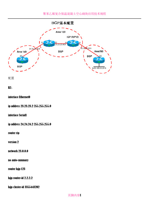
配置R2:interface Ethernet0ip address 23.23.23.2 255.255.255.0 interface Serial1ip address 24.24.24.2 255.255.255.0 router ripversion 2network 23.0.0.0no auto-summaryrouter bgp 123bgp router-id 2.2.2.2bgp cluster-id 3355443202bgp log-neighbor-changes neighbor 23.23.23.3 remote-as 123 neighbor 24.24.24.4 remote-as 140 R3:interface Ethernet0ip address 23.23.23.3 255.255.255.0 interface Serial1ip address 35.35.35.3 255.255.255.0 router ripversion 2network 23.0.0.0no auto-summaryrouter bgp 123no synchronizationbgp router-id 3.3.3.3bgp log-neighbor-changes neighbor 23.23.23.2 remote-as 123 neighbor 35.35.35.5 remote-as 150 no auto-summaryR4:interface Serial0ip address 24.24.24.4 255.255.255.0 router bgp 140bgp router-id 4.4.4.4bgp cluster-id 3355443203bgp log-neighbor-changes neighbor 24.24.24.2 remote-as 123 R5:interface Loopback0ip address 105.5.0.5 255.255.0.0 interface Serial0ip address 35.35.35.5 255.255.255.0 router bgp 150no synchronizationbgp router-id 5.5.5.5bgp log-neighbor-changes network 105.5.0.0 mask 255.255.0.0 neighbor 35.35.35.3 remote-as 123no auto-summary此时的实验结果为:R5#show ip bgpBGP table version is 2, local router ID is 5.5.5.5Status codes: s suppressed, d damped, h history, * valid, > best, i - internal, r RIB-failure, S StaleOrigin codes: i - IGP, e - EGP, ? - incompleteNetwork Next Hop MetricLocPrf Weight Path*> 105.5.0.0/16 0.0.0.0 0 32768 iR3#show ip bgpBGP table version is 2, local router ID is 3.3.3.3Status codes: s suppressed, d damped, h history, * valid, > best, i - internal, r RIB-failure, S StaleOrigin codes: i - IGP, e - EGP, ? - incompleteNetwork Next Hop Metric LocPrf Weight Path*> 105.5.0.0/16 35.35.35.5 0 0 150 iR2#show ip bgpBGP table version is 1, local router ID is 2.2.2.2Status codes: s suppressed, d damped, h history, * valid, > best, i - internalOrigin codes: i - IGP, e - EGP, ? - incompleteNetwork Next Hop MetricLocPrf Weight Path* i105.5.0.0/16 35.35.35.5 0 100 0 150 i此时在R2上的bgp路由并没有优化,原因为下一跳不可达。
bgp综合实验总结

——————————————袁月BGP综合实验1拓扑图拓扑说明:如图,有R1-R5五台路由器R1,R3,R4的S0/0、S0/1、S0/2口通过FR连接,R1为hub,帧中继链路ip为10.10.134.0/24R1,R2的F1/0口通过以太网连接,链路ip为10.10.12.0/24R4,R5的s0/1口直连,网段10.10.45.0/24每台路由器的环回0口ip为x.x.x.x/32R1上有lo1-lo5,ip地址为192.168.1.1/24---192.168.5.1/24R5上有lo1-lo5,ip地址为172.16.1.1/24---172.16.5.1/24实验要求:1.配置底层:配置每台设备的接口ip,配置完成后确保直连可达每个路由器的环回口是X.X.X.X/322.配置IGP全网运行OSPF area0,仅宣告lo0口和链路ip进入ospf,NBMA区域任意处理3.建立BGP邻居BGP AS区域划分如图,按照如下规则建立对等关系.使用回环口建立邻居.R1 peer R2R2 peer R1,R3R3 peer R2,R4R4 peer R5R5 peer R44.BGP 路由宣告邻居建立完成后,将R1和R5的lo0口宣告进入BGP,使用network命令要求R1,R5使用适当的方式宣告各自的lo1-lo5宣告完成后要求每台设备的bgp转发表可见这些路由5.BGP路由控制要求做出适当控制,达成下列条件,具体方法不限1、使下列条目出现在R1的bgp表中*> 172.16.1.0/24 2.2.2.2 100 0 255 2 3 i*> 172.16.2.0/24 2.2.2.2 255 10 20 2 3 ? *> 172.16.3.0/24 2.2.2.2 0 2 3 i*> 172.16.4.0/24 2.2.2.2 255 2 3 i*> 172.16.5.0/24 2.2.2.2 100 0 255 2 3 i2、使下列条目出现在R5的bgp表中*> 192.168.0.0/21 0.0.0.0 100 32768 2 1 i *> 192.168.1.0 4.4.4.4 0 2 1 i *> 192.168.2.0 4.4.4.4 0 2 1 is> 192.168.3.0 4.4.4.4 0 2 1 is> 192.168.4.0 4.4.4.4 0 2 1 i *> 192.168.5.0 4.4.4.4 0 2 1 i3、完成后,R1,R5互相可PING通对方宣告的这些bgp路由实验效果:R1上查看BGP表R5上查看BGP表BGP综合实验2拓扑图实验要求如下:1 R1与R2为EBGP R2与R3、R4为EBGP R3与R4为IBGP R3与R4、R5为EBGP每台路由器都有X.X.X.XX/32作为router-id 全网底层跑EIGRP 1002 R3、R4学到R1上的bgp路由下一跳必须为AS100的,R5上学到的R1和R3的路由,优走R33 在R1和R5上的回环口分别是20.20.20.0/24和30.30.30.0/24,都重分布到BGP中,使其相互学到并互相连通!实验效果:R3和R4上查看BGP表R5上查看路由表R1和R5上的lo0互相ping通BGP综合实验3拓扑图实验要求如下:1 R4上有192.168.1.0/24、192.168.2.0/24、192.168.3.0/24、192.168.4.0/24和100.100.100.0/24网段,R5上有172.16.1.0/24、172.16.2.0/24、172.16.3.0/24、172.16.4.0/24和50.50.50.1/32网段2 R1为DR,R2和R3不参与DR选举每台路由器都有x.x.x.x/24做为router-id3 Ospf学到的是192.168汇总和172.16的汇总以及100.100的明细路由4 EIGRP不能学到192.168的路由,能学到100.100的路由5 R4为AS100R2为AS200R5为AS300R4只与R2建立EBGP,R5只与R2建立EBGP,R4能学到50.50.50.1/32的路由,且可达!。
BGP 配置实例
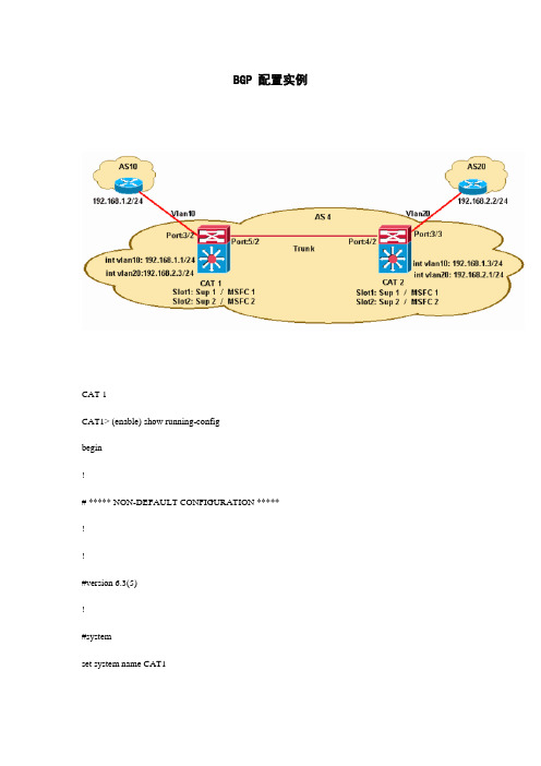
BGP 配置实例CAT 1CAT1> (enable) show running-configbegin!# ***** NON-DEFA ULT CONFIGURATION *****!!#version 6.3(5)!#systemset system name CAT1set system highavailability enable!-- Enables high availability on Catalyst switch.!#vtpset vtp domain ciscoset vlan 1 name default type ethernet mtu 1500 said 100001 state active [..]set vlan 10,20!#set boot commandset boot config-register 0x2102set boot system flash bootflash:cat6000-sup.6-3-5.bin!#module 3 : 48-port 10/100BaseTX Ethernetset vlan 10 3/2!-- Port 3/2 is connected to AS10 on VLAN 10.!#module 5 : 8-port 1000BaseX Ethernetset module name 5set trunk 5/2 on isl 1-1005,1025-4094!-- Port 5/2 is connected to CAT 2 as Trunk.!#module 15 : 1-port Multilayer Switch Feature Card!-- MSFC #1 on Port 1, Mod 15.!#module 16 : 1-port Multilayer Switch Feature Card!-- MSFC #2 on Port 2, Mod 16.CAT 2CAT2 (enable) show running-configbegin!# ***** NON-DEFA ULT CONFIGURATION *****!!#version 6.3(5)!#systemset system name CAT2set system highavailability enable!-- Enables high availability on Catalyst switch.!#vtpset vtp domain ciscoset vlan 1 name default type ethernet mtu 1500 said 100001 state active set vlan 10,20!#set boot commandset boot config-register 0x2102set boot system flash bootflash:cat6000-sup.6-3-5.bin !!#module 3 : 48-port 10/100BaseTX Ethernetset vlan 20 3/3!-- Port 3/3 is connected to AS20 on VLAN 20.!#module 4 : 8-port 1000BaseX Ethernetset module name 4set trunk 4/2 on isl 1-1005,1025-4094!-- Port 4/2 is connected to CAT 1 as Trunk.!#module 15 : 1-port Multilayer Switch Feature Card !-- MSFC 1 on Port 1, Mod 15.!#module 16 : 1-port Multilayer Switch Feature Card !-- MSFC #2 on Port 2, Mod 16.MSFC Configuration on CAT1CAT1> (enable)CAT1> (enable) session 15Trying Router-15...Connected to Router-15.Escape character is '^]'.MSFC-CAT1>enableMSFC-CAT1#show running-configBuilding configuration...Current configuration : 868 bytes!version 12.1!hostname MSFC-CAT1!boot system bootflash:c6msfc2-jsv-mz.121-8b.E7 !ip subnet-zero!!!redundancy!-- This command enables redundancy.high-availability!-- This command enables high availability. single-router-mode!-- This command enables SRM.!interface Vlan10ip address 192.168.1.1 255.255.255.0!-- Interface Vlan10 is connected to AS10.!interface Vlan20ip address 192.168.2.3 255.255.255.0!-- Interface Vlan20 is connected to interface Vlan20 on CAT2 via the trunk.!router bgp 4no synchronizationbgp log-neighbor-changesnetwork 192.168.0.0 mask 255.255.0.0neighbor 192.168.1.2 remote-as 10!-- This command establishes eBGP peering with AS10.neighbor 192.168.2.1 remote-as 4!-- This command establishes iBGP peering with interface VLAN 20 on CAT2.neighbor 192.168.2.1 next-hop-self!-- This command assigns a next-hop value to 192.168.2.3 !-- for updates sent to 192.168.2.1 (the iBGP peer).!ip classlessip route 192.168.0.0 255.255.0.0 Null0MSFC Configuration on CAT2CAT2 (enable)CAT2 (enable) session 15Trying Router-15...Connected to Router-15.Escape character is '^]'.MSFC-CAT2>enableMSFC-CAT2#show running-configBuilding configuration...Current configuration : 890 bytes!version 12.1!hostname MSFC-CAT2!boot system flash bootflash:c6msfc-jsv-mz.121-8b.E7 !ip subnet-zero!!redundancy!-- This command enables redundancy.high-availability!-- This command enables high availability.single-router-mode!-- This command enables SRM.!interface Vlan10ip address 192.168.1.3 255.255.255.0!-- Interface Vlan10 connected to interface Vlan10 on CAT1 via the trunk.!interface Vlan20ip address 192.168.2.1 255.255.255.0!-- Interface Vlan20 connected to AS20.!router bgp 4no synchronizationbgp log-neighbor-changesnetwork 192.168.0.0 mask 255.255.0.0neighbor 192.168.2.2 remote-as 20!-- This command establishes eBGP peering with AS20.neighbor 192.168.2.3 remote-as 4!-- This command establishes iBGP peering with interface Vlan20 on CAT1.neighbor 192.168.2.3 next-hop-self!-- This command assigns a next-hop value to 192.168.2.1 !-- for updates sent to 192.168.2.3 (the iBGP peer).!ip classlessip route 192.168.0.0 255.255.0.0 Null0TroubleshootNow that you've verified the high availability SRM configuration, you need to verify the BGP MSFC on CAT1 and CAT2. Use the show ip bgp summary command to verify the neighbor establishment. The output below confirms successful eBGP and iBGP peering with AS10 and the CAT2 MSFC respectively.MSFC-CAT1#show ip bgp summaryBGP router identifier 192.168.2.3, local AS number 4BGP table version is 4, main routing table version 43 network entries and4 paths using 435 bytes of memory4 BGP path attribute entries using 240 bytes of memory2 BGP AS-PATH entries using 48 bytes of memory0 BGP route-map cache entries using 0 bytes of memory0 BGP filter-list cache entries using 0 bytes of memoryBGP activity 3/14 prefixes, 4/0 paths, scan interval 15 secsNeighbor V AS MsgRcvd MsgSent TblVer InQ OutQ Up/Down State/PfxRcd192.168.1.2 4 10 90 92 4 0 0 01:26:02 1192.168.2.1 4 4 91 91 4 0 0 01:25:38 2Verify the BGP state on the active MSFC in CAT2. The output below confirms successful eBGP and iBGP peering with AS20 and CAT1 respectivelyMSFC-CAT2#show ip bgp summaryBGP router identifier 192.168.2.1, local AS number 4BGP table version is 4, main routing table version 43 network entries and4 paths using 435 bytes of memory4 BGP path attribute entries using 240 bytes of memory2 BGP AS-PATH entries using 48 bytes of memory0 BGP route-map cache entries using 0 bytes of memory0 BGP filter-list cache entries using 0 bytes of memoryBGP activity 3/0 prefixes, 4/0 paths, scan interval 15 secsNeighbor V AS MsgRcvd MsgSent TblVer InQ OutQ Up/Down State/PfxRcd192.168.2.2 4 20 110 112 4 0 0 01:46:43 1192.168.2.3 4 4 101 101 4 0 0 01:35:09 2In the event the designated MSFC (Mod 15 on CAT1) experiences a failure, the standby MSFC (Mod 16 on CAT1) takes over the role of active MSFC. It is important to understand that with the failure of the designated MSFC and fail over to the non-designated MSFC, packet switching will continue to work with the Cisco Express Forwarding (CEF) table programmed by the old designated MSFC. The newly designated MSFC will eventually re-program the CEF table with its own entries and the old entries will expire.Failure of designated MSFC is simulated by resetting Mod 15 on CAT1 as shown below.CAT1> (enable) reset 15This command will reset module 15.Unsaved configuration on module 15 will be lostDo you want to continue (y/n) [n]? y2002 May 16 11:52:54 %SYS-5-MOD_RESET:Module 15 reset from Console//Resetting module 15...Ping traffic was generated from AS10 to a destination in AS20 during the fail over on CAT1 from designated to non-designated MSFC. Note that there was minimal packet loss during this fail over and the packet forwarding continued to work with the old CEF table programmed by the Mod 15 MSFC until the Mod 16 MSFC re-programs the CEF table with its own entries.AS10-Router#pingProtocol [ip]:Target IP address: 172.16.1.1Repeat count [5]: 1000Datagram size [100]:Timeout in seconds [2]:Extended commands [n]:Sweep range of sizes [n]:Type escape sequence to abort.Sending 1000, 100-byte ICMP Echos to 172.16.1.1, timeout is 2 seconds: !!!!!!!!!!!!!!!!!!!!!!!!!!!!!!!!!!!!!!!!!!!!!!!!!!!!!!!!!!!!!!!!!!!!!!!!!!!!!!!!!!!!!!!!!!!!!!!!!!!!!!!!!!!!!!!!!!!!!!!!!!!!!!!!!!!!!!!!!!!!!!!!!!!!!!!!!!!!!!!!!!!!!!!!!!!!!!!!!!!!!!!!!!!!!!!!!!!!!!!!!!!!!!!!!!!!!!!!!!!!!!!!!!!!!!!!!!!!!!!!!!!!!!!!!!!!!!!!!!!!!!!!!!!!!!!!!!!!!!!!!!!!!!!!!!!!!!!!!!!!!!!!!!.!!!!!!!!!!!!!!!!!!!!!!!!!!!!!!!!!!!!!!!!!!!!!!!!!!!!!!!!!!!!!!!!!!!!!!!!!!!!!!!!!!!!!!!!!!!!!!!!!!!!!!!!!!!!!!!!!!!!!!!!!!!!!!!!!!!!!!!!!!!!!!!!!!!!!!!!!!!!!!!!!!!!!!!!!!!!!!!!!!!!!!!!!!!!!!!!!!!!!!!!!!!!!!!!!!!!!!!!!!!!!!!!!!!!!!!!!!!!!!!!!!!!!!!!!!!!!!!!!!!!!!!!!!!!!!!!!!!!!!!!!!!!!!!!!!!!!!!!!!!!!!!!!!!!!!!!!!!!!!!!!!!!!!!!!!!!!!!!!!!!!!!!!!!!!!!!!!!!!!!!!!!!!!!!!!!!!!!!!!!!!!!!!!!!!!!!!!!!!!!!!!!!!!!!!!!!!!!!!!!!!!!!!!!!!!!!!!!!!!!!!!!!!!!!!!!!!!!!!!!!!!!!!!!!!!!!!!!!!!!!!!!!!!!!!!!!!!!!!!!!!!!!!!!!!!!!!!!!!!!!!!!!!!!!!!!!!!!!!!!!!!!!!!!!!!!!!!!!!!!!!!!!!!!!!!!!!!!!!!!!!!!!!!!!!!!!!!!!!!!!!!!!!!!!!!!!!!!!!!!!!!!!!!!!!!!!!!!!!!!!!!!!!!!!!!!!!!!!!!!!!!!!!!!!!!!!!!!!!!!!!!!!!!!!!!!!!!Success rate is 99 percent (999/1000), round-trip min/avg/max = 1/3/116 ms。
BGP 基础配置实例

这次做一个BGP基本的实例://// r1 ////int lo1int lo2ip ad 192.1.25.1 255.255.255.0int f1/1ip ad 192.1.1.1 255.255.255.0router bgp 100neighbor 192.1.1.2 remote-as 200network 192.1.24.0network 192.1.25.0//// r2 ////int f1/1ip address 192.1.1.2 255.255.255.0int f3/3ip ad 193.1.1.2 255.255.255.0int f4/4ip ad 194.1.1.2 255.255.255.0router bgp 200neighbor 192.1.1.1 remote-as 100 neighbor 193.1.1.3 remote-as 200 neighbor 194.1.1.4 remote-as 300//// r3 ////int f3/3ip ad 193.1.1.3 255.255.255.0router bgp 300neighbor 193.1.1.2 remote-as 200 //// r4 ////int f4/4ip ad 194.1.1.4 255.255.255.0router bgp 400neighbor 194.1.1.2 remote-as 200基础配置完成后,一定要验证:show ip bgp summaryr2#sh ip bgp suBGP router identifier 194.1.1.2, local AS number 200BGP table version is 8, main routing table version 87 network entries and 7 paths using 931 bytes of memory3 BGP path attribute entries using 180 bytes of memory2 BGP AS-PATH entries using 48 bytes of memory0 BGP route-map cache entries using 0 bytes of memory0 BGP filter-list cache entries using 0 bytes of memoryBGP activity 7/46 prefixes, 7/0 paths, scan interval 15 secsNeighbor V AS MsgRcvd MsgSent TblVer InQ OutQ Up/Down State/PfxRcd 192.1.1.1 4 100 46 49 8 0 0 00:42:37 2193.1.1.3 4 200 46 52 8 0 0 00:42:06 0194.1.1.4 4 300 56 58 8 0 0 00:39:26 2show ip bgpr2#sh ip bgpBGP table version is 8, local router ID is 194.1.1.2Status codes: s suppressed, d damped, h history, * valid, >best, i - internal Origin codes: i - IGP, e - EGP, ? - incompleteNetwork Next Hop Metric LocPrf Weight Path*> 192.1.24.0 192.1.1.1 0 0 100 i*> 192.1.25.0 192.1.1.1 0 0 100 i*> 192.1.26.0 194.1.1.4 0 0 300 i*> 192.1.27.0 194.1.1.4 0 0 300 ir2#show ip ror2#sh ip roCodes: C - connected, S - static, I - IGRP, R - RIP, M - mobile, B - BGPD - EIGRP, EX - EIGRP external, O - OSPF, IA - OSPF inter area N1 - OSPF NSSA external type 1, N2 - OSPF NSSA external type 2 E1 - OSPF external type 1, E2 - OSPF external type 2,E - EGPi - IS-IS, L1 - IS-IS level-1, L2 - IS-IS level-2, ia - IS-IS inter area* - candidate default, U - per-user static route, o - ODRP - periodic downloaded static routeGateway of last resort is not setB 192.1.25.0/24 [20/0] via 192.1.1.1, 00:43:46B 192.1.24.0/24 [20/0] via 192.1.1.1, 00:43:46B 192.1.27.0/24 [20/0] via 194.1.1.4, 00:38:14B 192.1.26.0/24 [20/0] via 194.1.1.4, 00:38:14C 193.1.1.0/24 is directly connected, Serial0/0C 192.1.1.0/24 is directly connected, FastEthernet0/0C 194.1.1.0/24 is directly connected, FastEthernet0/1排错:我们在验证过程中,可观察到r1上的路由条目:show ip roB 192.1.27.0/24 [20/0] via 192.1.1.2, 00:38:14B 192.1.26.0/24 [20/0] via 192.1.1.2, 00:38:14C 192.1.1.0/24 is directly connected, f0/0路由表中含有26 27的路径,我们接下来用ping进一步验证。
一个BGP OSPF应用实例

�
1 在BGP中引入OSPF路由,发布给其它AS,在每个边界路由器中,OSPF引入BGP路由,发布给AS内部路由器,每个路由器都具有全部网络的路由,这种方式配置简单,缺点是域路由器需要较大的内存和处理能力,并且AS外部路由的波动会传递到AS内部,适用于网络中路由总数较小的情况;
2 在BGP中引入OSPF路由,经过路由聚合(有两种方式,一是通过aggregation命令动态聚合,一是通过配置静态路由并引入BGP的静态方法) 后发布给其它AS,在每个边界路由器中,OSPF引入BGP路由,发布给AS内部路由器。这样可以有效的减少AS外部路由,如果每个AS中分配的IP地址比较规整,通过配置少量的聚合命令就可以了,但在用户的网络中,经常有一些具有固定IP地址的子网从一个AS移动到另外一个AS去,而聚合的路由不能反映这种信息;
讨论主题:一个BGP/OSPF应用实例
libin 17533 作于 2000-09-13 09:05
类别: 经验共享
这是一个军队的用户采用BGP/OSPF组网的实例,整个网络划分为若干个AS,AS内部运行OSPF,AS之间运行BGP,每个AS都有多个边界路由器,为了扩展和配置管理的方便,采用路由反射器在边界路由器之间交换IBGP路由,反射器本身不作为边界路由器。为了提高可靠性,每个AS到AS1都有两个独立的BGP连接。解决AS外部的连通性有如下3种方案:
BGP后门链路(Backdoor)实际案例

BGP后门链路(Backdoor)实际案例(配图+详细验证过程Cisco提供一种方式强IGP路由优先于EBGP路由.这个概念也就是"后门链路"(backdoor link).EBGP 路由可以标记为后门链路,它将设置这些路由的管理距离与BGP本地或200相同.因为这个管理距离要高于IGP,所以首选IGP路由.以下是具体配置://// r1 ////int lo0ip ad 1.1.1.1 255.255.255.0int e1/0ip ad 192.1.1.1 255.255.255.0router os 1network 0.0.0.0 255.255.255.255 a 0 //将所有接口宣告进OSPFrouter bgp 200no syn //关闭同步,同时也注定了全互连的拓扑neighbor 192.1.1.2 remote-as 200neighbor 192.1.1.2 update-source lo0 //以lo0接口IP作为更新源地址//// r2 ////int lo0ip ad 2.2.2.2 255.255.255.0int e1/0ip ad 192.1.1.2 255.255.255.0int e0/0ip ad 193.1.1.2 255.255.255.0int e2/0ip ad 195.1.1.2 255.255.255.0router os 1network 0.0.0.0 255.255.255.255 a 0 //宣告所有接口进OSPFrouter bgp 200no synneighbor 192.1.1.1 remote-as 200neighbor 192.1.1.1 update-source lo0neighbor 192.1.1.1 next-hop-selfneighbor 195.1.1.5 remote-as 100network 192.1.1.0 mask 255.255.255.0//// r3 ////int lo0ip ad 3.3.3.3 255.255.255.0int e0/0ip ad 193.1.1.3 255.255.255.0int e1/0ip ad 194.1.1.3 255.255.255.0int e3/0ip ad 196.1.1.3 255.255.255.0router os 1netw 0.0.0.0 255.255.255.255 a 0router bgp 300no synneighbor 196.1.1.5 remote-as 100neighbor 194.1.1.4 remote-as 300neighbor 194.1.1.4 update-source lo0neighbor 194.1.1.4 next-hop-selfnetwork 194.1.1.0 mask 255.255.255.0//// r4 ////int lo0ip ad 4.4.4.4 255.255.255.0int e0/0ip ad 194.1.1.3 255.255.255.0router os 1network 0.0.0.0 255.255.255.255 a 0router bgp 300no synneighbor 194.1.1.3 remote-as 300neighbor 194.1.1.3 update-source lo0network 192.1.1.0 mask 255.255.255.0 backdoor//// r5 ////int lo0ip ad 5.5.5.5 255.255.255.0int e2/0ip ad 195.1.1.5 255.255.255.0int e3/0ip ad 196.1.1.5 255.255.255.0router bgp 100no synneighbor 195.1.1.2 remote-as 200neighbor 196.1.1.3 remote-as 300验证://后门链路作用前r2#sh ip bgpNetwork Next Hop Metric LocPrf Weight Path*> 192.1.1.0 0.0.0.0 0 32768 i*> 194.1.1.0 195.1.1.5 0 100 300 ir2#r2#r2#r2#sh ip ro bgpB 194.1.1.0/24 [20/0] via 195.1.1.5, 00:00:49r3#sh ip bgpNetwork Next Hop Metric LocPrf Weight Path *> 192.1.1.0 196.1.1.5 0 100 200 i *> 194.1.1.0 0.0.0.0 0 32768 ir3#sh ip ro bgpB 192.1.1.0/24 [20/0] via 196.1.1.5, 00:02:28r3#sh ip ro //后门链路作用前1.0.0.0/32 is subnetted, 1 subnetsO 1.1.1.1 [110/21] via 193.1.1.2, 00:04:22, Ethernet0/02.0.0.0/32 is subnetted, 1 subnetsO 2.2.2.2 [110/11] via 193.1.1.2, 00:04:22, Ethernet0/03.0.0.0/24 is subnetted, 1 subnetsC 3.3.3.0 is directly connected, Loopback04.0.0.0/32 is subnetted, 1 subnetsO 4.4.4.4 [110/11] via 194.1.1.4, 00:04:22, Ethernet1/0C 196.1.1.0/24 is directly connected, Serial3/0C 193.1.1.0/24 is directly connected, Ethernet0/0B 192.1.1.0/24 [20/0] via 196.1.1.5, 00:00:06O 195.1.1.0/24 [110/74] via 193.1.1.2, 00:04:22, Ethernet0/0 C 194.1.1.0/24 is directly connected, Ethernet1/0//后门链路作用后r3#sh ip ro1.0.0.0/32 is subnetted, 1 subnetsO 1.1.1.1 [110/21] via 193.1.1.2, 00:06:38, Ethernet0/02.0.0.0/32 is subnetted, 1 subnetsO 2.2.2.2 [110/11] via 193.1.1.2, 00:06:38, Ethernet0/03.0.0.0/24 is subnetted, 1 subnetsC 3.3.3.0 is directly connected, Loopback04.0.0.0/32 is subnetted, 1 subnetsO 4.4.4.4 [110/11] via 194.1.1.4, 00:06:38, Ethernet1/0C 196.1.1.0/24 is directly connected, Serial3/0C 193.1.1.0/24 is directly connected, Ethernet0/0O 192.1.1.0/24 [110/20] via 193.1.1.2, 00:00:06, Ethernet0/0O 195.1.1.0/24 [110/74] via 193.1.1.2, 00:06:38, Ethernet0/0 C 194.1.1.0/24 is directly connected, Ethernet1/0。
bgp选路案例

bgp选路案例
以下是一个BGP选路案例:
假设有两个自治系统AS100和AS300,其中AS100内部有两个路由器R1和R2,R1和R2之间运行BGP协议。
AS300内部有一个路由器R3,R3
和R1之间也运行BGP协议。
现在,我们想要让R3发送的数据包能够到达AS100外部的某个目标地址,例如。
我们可以通过配置BGP路由策略来实现这一目标。
首先,我们需要在R2上配置一个路由策略,将所有来自R3的路由标记为
高优先级。
这可以通过在R2上创建一个路由映射并应用一个前缀列表来实现。
前缀列表可以匹配R3的IP地址范围,并将其标记为高优先级。
接下来,我们需要在R1上配置一个路由策略,根据BGP路由的优先级进行选路。
我们可以创建一个路由映射,并在其中定义一个条件,以选择优先级更高的路由。
在我们的例子中,我们将选择来自R2的路由,因为我们已经
将所有来自R3的路由标记为高优先级。
最后,我们需要在R1上将所有目标地址为的路由发布到BGP协议中。
这可以通过创建一个BGP网络命令来实现。
通过这些配置,当R3发送数据包到目标地址时,BGP协议将选择通过R2和R1到达该地址的路径,而不是直接通过AS300到达该地址的路径。
这就是BGP选路的一个简单示例。
需要注意的是,实际的BGP选路可能会更加复杂,需要考虑更多的因素,例如路径的稳定性、可用性、性能等。
因此,在实际的网络设计中,需要根据具体情况进行详细的规划和配置。
BGP配置实例及路由注入讲解

BGP配置及路由注入实例讲解路由协议包括很多种,例如RIP、OSPF、IS-IS、BGP等等。
前面部分章节已看过OSPF和ISIS的实例。
今天我们来看看BGP路由协议。
首先我们通过下图先来回顾一下BGP在网络中的部署位置:简单地说:BGP属于外部网关协议,一般部署于自治系统之间(例如我们在两个运营商之间部署,或两个大企业网之间部署。
当然有些运营商内部使用了多种IGP协议,此时也在一个运营商内部使用,此种场景多见于城域网-省网-国网)。
说到BGP路由协议,必然会涉及到路由注入(有些人也叫做路由引入import-route XXX)。
举个简单例子,有A和B两个企业(或运营商),均部署了不同的IGP路由协议,中间使用BGP连接。
其中B企业(运营商)内部建设了一个http网站,此时A企业(运营商)的客户需要访问该网站,则需要涉及路由注入。
一、BGP配置实例讲解1、配置环境:(1)基本组网图:(2)组网说明:1、上图中左侧为A企业,配置了IS-IS路由协议,右侧为B企业,配置了OSPF协议。
2、目前A企业内各设备能够通过IS-IS协议通信,B企业内各设备能够通过OSPF协议通信。
3、分别查看部署BGP前A-R1和B-R1的IP路由表,如下:4、因前期部分章节已说明ISIS和OSPF的配置,本节不再说明。
如有需要,请从上下载(文件位置:网站→文件共享→BGP配置实验,压缩包里有“配置bgp 前网络拓扑及数据配置”)2、配置目标:在路由器A-R1和B-R1之间部署EBGP,使用对端的物理接口作为反射器的源接口。
3、数据规划:4、配置步骤:配置BGP(包括AS、peer)a.配置路由器A-R1的BGP。
命令如下:bgp 65001router-id 1.1.1.1peer 12.12.12.2 as-number 65002peer 12.12.12.2 connect-interface GigabitEthernet 0/0/0quitb.配置路由器B-R1的BGP。
bgp路由控制案例

bgp路由控制案例
以下是一个关于BGP路由控制的案例:
某大型网络中,有两个自治系统(AS)100和200。
在两个自治系统之间,存在一个流量工程的需求,需要在两个自治系统之间建立稳定的路径,同时需要控制流量经过的路径。
首先,在AS 100和AS 200之间建立BGP邻居关系,使用EBGP(外部BGP)协议进行路由的通告和传递。
在建立BGP邻居关系时,需要确保TCP连接可达,因为BGP是基于TCP封装进行通信的。
接下来,通过修改BGP的Loca- Preference值和MED(Multi-Exit Discriminator)值来实现路由的选择和路径的选路。
Loca- Preference值
用于选择离开本地自治系统的最佳路由,修改该值可以影响路由的选择。
而MED值用于选择进入自治系统的最佳路由,修改该值可以影响路径的选路。
此外,配置BGP的next-hop-local参数可以将自身地址作为下一跳地址,这样在转发数据包时可以避免经过不必要的路由器,提高路由效率。
最后,通过过滤器来控制路由的发布和接收。
例如,可以过滤掉不希望的路由,或者只接收特定路径的路由。
通过上述步骤,可以实现BGP路由的控制和选择,满足流量工程的需求,并保证网络的高可用性和稳定性。
最新个人总结的BGP心得-包含大量实验环境和配置案例

个人总结的B G P心得-包含大量实验环境和配置案例<BGP(Border Gateway Protocol)理论部分>·BGP属于EGP,是高级DV协议,也被称为路径矢量协议,基于TCP 179端口。
·现在使用版本BGP4。
第一次做完整更新,以后就只增量更新·Autonomous Systems:运行同一种选路策略,由统一管理者管理。
1-64511(公有)64512-65535(私有)电信AS号:4134 网通AS号:9929 一个好的网站,可以了解到关于AS号的一些信息Telnet 这一地址可以看到公网上的路由条目数·IGP支持的路由条目有限运行IGP不利于管理,做路由聚合、选路。
·BGP路由器只能将其使用的路由通告给他的邻居。
BGP用Open报文建邻居,用KL报文做日常联系·Neighbor table :List of BGP neighbors·BGP forwarding table/databaseList of all networks learned from each neighborCan contain multiple pathways to destination networksDatabase contains BGP attributes for each pathway·IP routing tableList of best paths to destination networksBGP表和路由表是独立的,同样遵循AD小的进入路由表。
BGP默认不做负载均衡·Router-ID选举和OSPF一致。
四种报文:Open ---includes holdtime and BGP router ID(用于建立TCP连接后,发起BGP会话,每个邻居都用该消息来标识自己,并且规定自己的BGP运行参数)Keepalive —(用于保持BGP会话,每隔60秒发送一次,hold time为180S)Update ---information for one path only (could be to multiple networks)---Includes path attributes and networks·一个UPDATE 消息一次只能通告一条路由,但它可以携带多个属性。
- 1、下载文档前请自行甄别文档内容的完整性,平台不提供额外的编辑、内容补充、找答案等附加服务。
- 2、"仅部分预览"的文档,不可在线预览部分如存在完整性等问题,可反馈申请退款(可完整预览的文档不适用该条件!)。
- 3、如文档侵犯您的权益,请联系客服反馈,我们会尽快为您处理(人工客服工作时间:9:00-18:30)。
下面是一个BGP 综合实例,其中涉及到路由聚合、静态路由的再分配等BGP 功能的实际应用。
R4 和R1 建立EBGP,R1 和R2 建立IBGP,R2 和R5 建立多跳EBGP。
其中,假设R4 中存在图中右上角标注的四条静态路由。
在R4 的配置中,仅聚合通告192.16.0.0/16 网段,并且通过路由图禁止通过BGP 对外通告170.16.10.0/24 网段。
R2 与R5 之间通过R3 建立EBGP 多跳关系,此时在配置BGP 之前需要保证该两台路由器建立邻居的地址能够互通。
R4 的配置:
ZXR10_R4(config)#router bgp 2
ZXR10_R4(config-router)#redistribute static
ZXR10_R4(config-router)#neighbor 172.16.20.2 remote-as 1
ZXR10_R4(config-router)#aggregate-address 192.16.0.0 255.255.0.0 count 0 as-set summary-only
ZXR10_R4(config-router)#neighbor 172.16.20.2 route-map torouter1 out ZXR10_R4(config-router)#exit
ZXR10_R4(config)#ip access-list standard 1
ZXR10_R4(config-std-acl)#permit 172.16.10.0 0.0.0.255
ZXR10_R4(config-std-acl)#exit
ZXR10_R4(config)#route-map torouter1 deny 10
ZXR10_R4(config-route-map)#match ip address 1
ZXR10_R4(config)#route-map torouter1 permit 20
R1 的配置:
ZXR10_R1(config)#router bgp 1
ZXR10_R1(config-router)#no synchronization
ZXR10_R1(config-router)#neighbor 172.16.1.2 remote-as 1
ZXR10_R1(config-router)#neighbor 172.16.1.2 next-hop-self
ZXR10_R1(config-router)#neighbor 172.16.20.1 remote-as 2
R2 的配置:
ZXR10_R2(config)#ip route 183.16.0.0 255.255.0.0 fei_1/4
ZXR10_R2(config)#router bgp 1
ZXR10_R2(config-router)#neighbor 172.16.1.1 remote-as 1
ZXR10_R2(config-router)#neighbor 172.16.1.1 next-hop-self
ZXR10_R2(config-router)#neighbor 183.16.20.2 remote-as 3
ZXR10_R2(config-router)#neighbor 183.16.20.2 ebgp-multihop ttl 2 ZXR10_R2(config-router)#neighbor 183.16.20.2 route-map torouter5 in ZXR10_R2(config-router)#exit
ZXR10_R2(config)#ip access-list standard 1
ZXR10_R2(config-std-acl)#permit 155.16.10.0 0.0.0.255
ZXR10_R2(config-std-acl)#exit
ZXR10_R2(config)#route-map torouter5 deny 10
ZXR10_R2(config-route-map)#match ip address 1
ZXR10_R2(config)#route-map torouter5 permit 20
R5 的配置:
ZXR10_R5(config)#ip route 173.16.0.0 255.255.0.0 gei_1/1
ZXR10_R5(config)#router bgp 3
ZXR10_R5(config-router)#neighbor 173.16.20.2 remote-as 1
ZXR10_R5(config-router)#neighbor 173.16.20.2 ebgp-multihop ttl 2。
