燃气调压阀R622-5说明书
气压阀软硬件功能规格说明书
气压阀软硬件功能规格说明书XXX煤矿水管路减压阀应用案例,现在介绍气动压力调节阀技术规格书气动减压调节阀技术要求:减压阀是通过节流口的节流作用而减压的,这就是说,只用气体流动时,减压阀才能减压,当气体不流动时(比如气缸处于静止状态),减压阀节流C 就不能减压,此时应该应用“帕斯卡定律”,气体各处压力相等,等于气源的压力。
汽缸压力的增加,进气阀门的开度逐渐减小,直到输出口力p2与压头上的作用力相平衡时进气阀门关闭。
当外力消除后,进气阀i 在气压和复位弹簧2的力作用下,向上移动关闭。
与此同时压头与排气阀[ ]在复位弹簧1的力及排气压力的作用下复位,排气口开启,原输出的气体由排气阀[ ]经消声器排入大气。
气动压力调节阀是一种压力平衡式调节阀,采用单座、套筒导向、双密封结构,配用多弹簧4气动薄膜执行机构,执行机构高度低、重重轻、装备简便。
气动压力调节阀配以阀广定位器,将电流信号转变成像对应的直线位移,自动地控制调节阀开度,达到对管道内流体的压力参数的连续调节。
属于自动阀,工作时它自动接收信号,检测信号、反馈信号,自动调节介质参数。
根据调节效果可分为线性特性等百分性、抛物线特性三种。
该气动调节阀具有调节度高、可调范围大、故障失气失信号时可弹簧复位开启或关闭。
气动压力调节阀技术规格书结构特点:1、气动调节阀阀座采用卡入式构造防止了螺纹旋入式的缺陷,当压紧上盖时阀芯和阀座自动对中,而且装卸复杂方便,即便在严重腐蚀的状况下也能轻松地取出阀座,有利于维修和维护。
2、调节阀阀芯和阀杆采用一体式构造防止了插销式的缺陷,即便在高压差的状况下更能保证阀杆的波动性。
3、在整个流量和特性范围内,均衡型和非均衡型阀塞,具有很高的切断密封功能。
4、调节阀中采用均衡阀塞,可以接受比拟大的允许压差。
5、阀内件外表特殊处置,抛光、氮化和堆焊司钛莱合金延伸了调节阀的运用寿命,任务更焉牢靠,7.可调比50:1。
6、采用多弹簧型气动执行机构,可完成正、反作用,不需求添加其他零件就能调整弹簧范围,正作用执行机构可以完成气闭操作,反作用执行机构可完成气讦操作。
SGV减压阀使用说明书

¥安装使用前请仔细阅读并妥善保存本说明书。
¥所有本说明书所列操作只能由经过合格培训的人员进行。
¥错误的安装、调试、改动、操作或维护可能会带来人身安全及财产损失。
¥安装还应该遵照其他相应的有关法规。
¥未按照本说明书实施的不当操作而导致产品的损坏及其他直接或间接的损失,与本公司无关。
ŸSGV 系列调压阀适用于调节燃烧系统的燃气压力。
工作介质包括天然气、城市煤气和空气等非腐蚀性气体。
Ÿ使用温度:-10~60℃。
注意:严格禁止采取先安装本产品再进行管道焊接的安装方式,避免焊接时的高温、焊渣和电弧等损坏阀门。
Ÿ阀体上箭头指示气流方向,必须按照阀体上面标识的流向方向安装。
Ÿ安装应避免产生机械应力。
Ÿ可安装在水平或垂直管路上,安装时弹簧腔垂直向上或水平位置,不得低于水平线Ÿ阀体与附近固定构筑物的最小距离应不小于50mm。
Ÿ安装时需防止密封材料及其他杂物进到本产品或管道内。
Ÿ不要露天存放或者安装。
Ÿ强烈建议在上游管道安装过滤器Ÿ安装本产品于管道上时请使用合适的工具,切勿通过扳动产品本身来安装。
注意:最大入口压力为1bar和4bar的减压阀都必须正确安装反馈管,否则阀门无法正常工作。
Ÿ反馈管接口为Rp3/8'',接头适配Φ12ⅹ1铜管。
Ÿ反馈管取压点必须在距离阀门出口(或阀门出口变径后)5倍管径的直管段处。
用盲板封闭阀门前端和后端管路;‚通入低压测试气体,用肥皂水喷刷管路与阀门入口连接处(及反馈管连接处),如连接处有气泡冒出,则连接处有泄露;ƒ气密性检测完成后移去盲板。
注意:本产品严禁高压打压检漏!管道低压检漏前必须关闭本产品的下游阀门或用盲板将出口端堵住,上游接入压力最高不得超过标签上所标注的最大入口压力P 。
I 警告:检漏或正常送气时,减压阀上游手动切断阀先缓慢打开一个小开度,然后停止动作,待手动切断阀前后压力平衡后再继续打开手动切断阀至所需开度,整个过程中避免瞬间高压损坏减压阀。
燃气调压装置使用说明书
西气东输-平舞漯地方支线工程燃气调压装置使用说明书尊敬的用户:感谢您选用费希尔久安燃气调压装置,为保证燃气调压装置安全工作和设备正常供气,安装操作前请仔细阅读本说明书以及各单体设备使用说明书的有关内容。
说明书应妥善保存,以备查询。
费希尔久安输配设备(成都)有限公司Fisher Jeon Gas Equipment (Chengdu) Co.,Ltd目录1概述 (3)2主要参数 (4)2.1各站主要参数 (4)2.2型号说明 (5)3燃气调压装置的安装程序 (6)4燃气调压装置的运行与调试 (7)4.1空气置换 (7)4.2运行前的准备及注意事项 (8)4.3气密性试验 (9)4.4调试运行程序 (10)4.5调压器参数设定 (12)4.6工作管路与备用管路的人工切换方法 (14)4.7停机的操作程序 (15)5常见故障分析与排除 (16)6燃气调压装置的维修保养 (18)6.1检修周期及维修程序 (19)6.2维护保养中的注意事项 (21)7尺寸,重量及吊装 (22)7.1设备尺寸及重量 (22)7.2设备吊装 (22)8售后服务 (23)1概述(燃气调压装置是在城镇燃气输配系统中,专为城市门站、分输站、储配站、燃气轮机、燃气锅炉、燃气发电厂或其他大型专用用户设计的成套调压设备。
通常具有接收气源来气、燃气净化、燃气调压、气量分配、计量、安全保护等功能;采用整体橇装形式,所有功能模块集成于一个或多个撬座上。
根据工程条件和系统需要,还可增设消音设备、加热设备、监控及数据采集设备、加臭装置、清管设备等功能模块。
具有安全性好、可靠性高、经济性能良好、占地面积小、内部结构优化合理、安装调试简单、测试维修方便等特点。
本燃气调压装置按照我国现行国家标准GB50028《城镇燃气设计规范》及我公司企业标准Q/76227017-0.1-2006《撬装式城镇燃气调压装置》执行。
)本说明书主要介绍燃气调压装置的主要参数、结构特点、主要设备、安装运行调试方法、故障处理、维修保养等内容。
燃气调压箱(柜)使用说明书
燃气调压箱(柜)使用说明书成都科瑞尔低温设备有限公司目录一用途/范围 (3)二基本功能及特点 (4)1、基本功能 (4)2、特点 (4)三燃气调压箱(柜)类型 (5)四燃气调压箱(柜)工艺流程 (5)五燃气调压箱(柜)主要型号技术参数 (6)六燃气调压箱(柜)的安装与使用 (7)七燃气调压箱(柜)的维护 (9)八燃气调压箱(柜)常见故障处理 (10)九注意事项 (13)十订货须知 (14)一用途/范围本资料适用于燃气调压箱(柜),所介绍的燃气调压箱(柜)是按常规采用的输配工艺布置,同时根据用户提供的参数及选配的设备来设计生产。
二基本功能及特点1、基本功能◆燃气净化:对燃气进行过滤,以保证系统内设备正常工作。
◆燃气调压:将上游管网的燃气压力降至下游管网或管道所需的使用压力,并保持在规定的范围内,且不随上游压力和流量的变化而变化。
◆切断保护:当出口压力高于设定压力一定值,进行切断保护。
◆安全保护:当下游压力因故超过系统规定的压力范围时,对下游气流进行控制或对上游气流进行截流,以保证安全用气。
◆流量计量:对燃气流量进行测量并换算为标准状态下的流量。
◆自控系统:对运行状况进行遥测遥讯遥控。
◆报警系统:对泄漏、故障进行报警。
◆加臭装置:将臭液加入燃气中使之具有臭味。
2、特点◆集调压、过滤、计量、安全放散等为一体,系统协调性好、可靠性高。
◆计量前后气流稳定,计量精准、可靠。
◆安装、调试简单,使用、维护方便。
◆适用于天然气、人工煤气、石油液化气及其它无腐蚀性气体。
◆扩展性好,可根据用户要求增添功能。
◆设备出厂前均经强度、气密性试验,各参数均按用户要求设定,现场操作简单、方便。
◆可无人值守,只需定期检查。
三燃气调压箱(柜)类型◆按用户类型分为:首站、门站、高中压调压站、民用区域调压柜、工业专用等。
◆按进出口压力分为:高中压、高低压、中中压、中低压。
◆按结构类型分为:橇装式、柜式、箱式。
◆按调压管路数分为:1+0、1+1、2+0、2+1、其他。
燃气自闭阀使用说明、技术参数、产品功能、使用方法和使用注意事项
燃气自闭阀使用说明、技术参数、产品功能、使用方法和使用注意事项概述燃气自闭阀安装于低压燃气系统管道上,当管道供气压力出现欠压、超压时,不用电或其它外部动力,能自动关闭并须手动开启的装置技术参数执行标准:CJ/T447-2014工作温度:-10C<T<40C超压自动关闭压力:8KPa士2KPa欠压自动关闭压力:08KPa02KPa连接尺寸:进口螺纹为G1/2,出口为G1/2或直径9.5产品功能3.1、超流切断功能:当燃气胶管松动脱落、烧断。
鼠咬、破裂超过设定流量时,阀门自动切断气源。
气压突然升高超过安全压力时造成流量超值,阀门自动切断起源。
3.2、超压保护功能:当调压器失灵值,阀门自动切断气源。
3.3、超低压功能:当燃气管道供气气压不足,阀门自动关闭气源3.4、停气关闭功能:燃气管道因类发事件、故障检修等原因停止供气时、阀门自动关闭气源3.5、微漏检测功能:关闭燃具开关,拉开自闭阀旋钮,再关闭进气闷、观察10-20分钟后自闭阀保持开启状态,说明胶管及接口和燃县开关均为正常。
使用方法4.1、在管道正常通气状态下,拉起红色提即可用气。
4.2、如提钮自动吸回时,应注意检在以下情况a 、软管是否有破裂现象。
B、接口是否脱落c、是否停气使用注意事项5.1、自闭阀应由有资质专业人员安装。
5.2、必须使用符合国家标准的熄火保护燃气灶具5.3、自闭严禁浸水5.4、自闭阀具有微漏检测功能,用户应定期自行自检5.5、需经常检查燃气胶管及接头处,若出现老化裂痕、鼠等小微破损,泄潜量并未超过规定的过流关闭值,此时自闭阀不会自闭,应及时更换燃气胶管5.6禁止私自拆卸自闭阀5.7、如果发现室内有燃气异味,应立即打开门窗通风、禁止在现场打电话、开灯或用火,禁止使用灶具。
调压器操作指导书
调压器操作指导书1 主要内容及适用范围本指导书规定了燃气调压器运行的检查准备、操作程序和注意事项。
本指导书适用于中石油昆仑燃气有限公司调压器的投用、压力设置和系统运行切换等作业。
2 检查与准备2.1 操作人员要明确所操作燃气系统的压力等工艺参数设置要求。
2.2 检查所用工具、物品是否齐全,穿戴好工作服及劳保用品。
2.3 设定操作压力应遵循由高到低的原则,按步骤逐项进行。
一般设置压力顺序为:放散压力、切断压力、工作压力。
各用气场所可根据其用气特点要求和侧重保护方式的不同,调整各压力的设定值并结合工作实际调整压力设置。
3 操作程序3.1 调压器的投用3.1.1 确认调压器的进出口阀门已关闭。
3.1.2 测试切断阀的复位操作,确认切断阀设置压力正确并处于正常工作状态。
测试中切断阀或附加在调压器上的切断阀在执行了切断动作后须人工进行复位。
3.1.3 测试放散阀,确认放散阀设置压力正确并处于正常工作状态。
打开放散阀前边的控制阀门,使放散管路通畅,放散阀连接的放散管要符合安全要求。
3.1.4 缓慢开启进口阀门,并观察上游压力表是否在允许的压力范围,为避免出口压力表在送气时超量程损坏,可先关闭压力表下阀门,待压力稳定后再开启。
3.1.5 当进口压力正常后,缓慢开启调压器出口阀门,并精确调节调压器的出口压力。
3.1.6 缓慢开启调压器进口阀门,观察低压端压力,压力平稳后逐步全部开启调压器的进出口阀门,实现对系统供气。
3.1.7 低温天气投用调压器要进行排污和保温防冻等措施。
3.1.8 调压器初次投用要加强巡检次数并做好记录。
3.2 调压器的压力设定3.2.1 运行压力的设定3.2.1.1 开启进气阀门前,应仔细检查调压器的所有阀门是否处于关闭状态。
3.2.1.2 缓慢打开主路调压器上燃气入口阀门,并打开进气总管上压力表的控制阀门,观察压力情况。
3.2.1.3 在入口压力稳定状态下,打开调压器前的阀门,缓慢打开监控调压器的调节螺栓,直至达到监控调压器的出口设定压力,锁定监控调压器调节螺栓(若无监控调压器则无此操作步骤)。
燃气设备操作手册(多种)
设备操作维护规程〔修订版〕2021年2月27日目录第一章手动阀门操作维护规程第二章电动阀门操作维护规程第三章气液联动阀门操作维护规程第四章过滤器的操作维护规程第五章燃气自动加臭装置操作维护规程第六章弹簧式平安阀操作维护规程第七章调压撬操作维护规程第八章切断阀操作维护规程第九章调压器操作维护规程第十章可燃气体报警装置操作维护规程第十一章柴油发电机操作维护规程第十二章流量计操作维护规程第十三章仪表操作维护规程第十四章低压配电控制柜操作维护规程第十五章消防设备操作维护规程第十六章阀门井操作维护规程第十七章调压柜〔箱〕操作维护规程第十八章管壳式换热器操作维护规程第十九章热水锅炉操作维护规程第二十章CNG调压站操作维护规程第二十一章天然气压缩机操作维护规程第二十二章枯燥器操作维护规程第二十三章售气机操作维护规程第二十四章立式离心泵操作维护规程第二十五章液化天然气焊接绝热气瓶操作维护规程第二十六章 LNG储罐操作维护规程第二十七章电锤操作规程第二十八章 PE电熔焊机操作维护规程第二十九章 PE热熔对焊机操作维护规程第三十章电动开孔机操作维护规程第三十一章 (220V-380V)汽油发电机操作维护规程第三十二章空气压缩机〔柴油机〕的操作维护规程第三十三章手砂轮操作维护规程第三十四章电动套丝机操作维护规程第三十五章电动开孔机操作维护规程第三十六章电焊机操作维护规程第三十七章手提式可燃气体检漏仪操作维护规程第三十八章 F型电热水浴式气化器操作维护规程第三十九章注油器操作维护规程第四十章镀层测厚仪操作维护规程第四十一章SP-Ⅲ型氧气检测报警仪操作维护规程第四十二章针孔探测仪〔火花检漏仪〕操作维护规程第四十三章变频气绝缘携带式Χ射线探伤机操作维护规程第四十四章 SWG-2A型液压弯管机操作维护规程序言为保证运营部燃气设备的正常运行,预防事故发生,使运行人员能按照操作维护规程对燃气设备进行巡视、操作、记录、检查、维修等常规工作,特制定本规程。
天然气调压区调压阀操作规程

天然气调压区调压阀操作规程一、新费舍阀(13,FISHER自励式调节阀)流程的操作规程1、检查新费舍阀(13)前后所有管线正常,无泄漏情况。
2、检查进气总管压力表指示正常,压力应在2.0-2.3MPa之间。
3、手动打开新费舍阀前的隔离阀(12),检查费舍阀阀前压力表指示正常,压力应在2.0-2.3MPa之间。
4、手动缓慢打开费舍阀后的隔离阀(14),检查费舍阀阀后压力表指示,压力应在1.6MPa左右。
5、新费舍阀(13)后压力值高于1.8MPa或低于1.55MPa时,可对新费舍阀进行调节,使新费舍阀阀后压力维持在1.6MPa左右。
调节方法如下:5.1、松开新费舍阀(13)调节器上的固定螺母。
5.2、调节调节器上的螺杆,顺时针调整时,新费舍阀阀后压力增大。
逆时针调整时,新费舍阀阀后压力减小。
5.3、调节调节器上的螺杆,使新费舍阀阀后压力维持在1.6MPa左右后,固定好调节器上的固定螺母。
6、检查天然气管线无泄漏情况,各压力表指示正常。
二、新费舍阀异常情况下流程切换的操作规程当新费舍阀(13)后压力值高于1.8 MPa或低于1.55MPa,对新费舍阀进行调节后,压力仍然无法恢复正常时,必须对新费舍阀流程进行切换操作。
1、手动打开旧费舍阀(16,FISHER副自励式调节阀)前的隔离阀15,检查旧费舍阀(16)阀前压力表指示正常,压力应在2.0-2.3MPa之间。
2、手动缓慢打开旧费舍阀(16)后的隔离阀17,检查加热器后集气母管压力表指示,压力应在1.65MPa左右。
3、手动关闭新费舍阀(13)阀前、后的隔离阀12、14。
4、当旧费舍阀(16)也出现故障时,手动打开费舍阀的两个旁路阀51、52;5、关闭旧费舍阀(16)前、后隔离阀15、17。
6、联系输气总站降低来气压力,使旧费舍阀后的压力低于1.8MPa。
三、天然气调压区夏季巡视检查内容1、检查天然气压力、温度、流量表计指示正常。
2、检查天然气各阀门的位置正常、无泄漏情况。
Fisher627减压阀
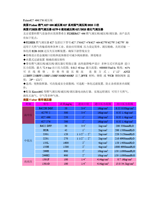
Fisher627-496/576减压阀
美国Fisher燃气627-496减压阀627系列煤气调压阀DN25口径
美国FISHER燃气调压器627W-5液相减压阀627/DN25液化气调压器
北京爱墨科燃气设备供应美国费希尔FISHER627-496燃气调压阀/减压阀/调压器,该产品具有如下优点:
◆FISHER燃气调压器627包括以下型号:627-576/627-476/627-464/627W/627W-5/627W- 30 适用于天然气传输系统和各种工业、商业应用领域压力设定简单、调压精确、关闭灵敏一体化的EZR-OSX过压失压切断装置,确保下游管线安全
◆特殊设计的金属阀口结构和流体路径可减少阀座磨损,降低噪音
◆内置式过滤装置精确的调压特性
◆带有燃气调压阀/减压阀/调压器行程指示器高性能降噪声设计多种方式可供选择进口压力范围:最大72.4 bar出口压力范围:0.015-48 bar 最大流量:400000 Nm3/h 精度:±1% 可在线维修,价格性能比极高连接方式:1"-12" ANSI 125BFF/250BFF/150RF/150RF/300RF/600RF 法兰,BWE 材料:铸铁或WCB 钢制阀体温度:-29°~121℃
◆选项:变换指挥器,可改装成安全放散阀;可选配一体化过滤装置,防止杂质损害内部配件;
◆配备Kixcel662型燃气调压阀/减压阀/调压器电动执行器,实现远程调压可用于天然气、液化石油气、空气等多种气体。
燃气调压装置说明书
CNG燃气调压装置KHRTQ100/200-2SJ使用说明书目录1、概述 (1)2、用途 (2)3、设计、制造依据 (2)4、技术参数 (3)5、设计参数 (3)6、安装说明 (4)7、操作说明 (5)8、维修与点检 (7)9、故障处理 (8)10、保证与服务 (9)燃气调压装置1、概述随着我国能源结构的变化和环保力度的不断加大,使天然气的开发和利用得到迅猛的发展;压缩天然气是把井口天然气或管道天然气净化压缩后进行高压储存和运输,到达使用地点,经过多级换热、调压直接输入管网供应各类用户;因而它具有系统简单、方便灵活特点;该系统使用地距加压站在300公里以内为经济范围,一般不超过500公里;该系统比较长输管线具有投资额度小、建设周期短、资金回收快特点;将来可为长输管线提供调峰和备用气源;压缩天然气英文缩写为CNG释放站实际上是一种特殊的调压装置;原则上采用两路配置,一开一备;每路采用两级或三级调压方式;换热方式可采温水循环式简称“温水式”或电热式;调压方式可选用自力式靠自身能源调压或从动式靠外来能源调压;输入方式可选用单入口或者双入口;将充满压缩天然气撬的车拉至供气站,把卸气台上的高压软管与CNG撬连接,通过高压管路,天然气进入释放装置;天然气进入释放装置后,先经过滤器,再经两级换热器进行加热,加热后的天然气经二级调压,把压力调至所要求的压力;供水系统保证天然气减压所需要的热能,空压机保证调压采用从动调压方式和紧急切断所需要的仪表风,操控台对整个供气站实现监控,在换热、调压过程中,具有天然气温度低保护、中间级出口压力超压保护超压切断和安全放散,释放装置出口压力超压保护超压切断和安全放散;压缩天然气经释放装置调压后,再经计量,进入管网;2、用途本装置主要适用于采用压缩天然气供气的场所,如中、小城市、企业和饭店、酒店;3、设计、制造依据特种设备安全监察条例JB/T 11491-2013 撬装式燃气减压装置TSG D2001-2006 压力管道元件制造许可规则TSG Z0004-2007 特种设备制造、安装、改造、维修质量保证体系基本要求GB50028-2006 城镇燃气设计规范GB50235-2010 工业金属管道工程施工规范GB50236-2011 现场设备、工业管道焊接工程施工规范GB50316-2000 工业金属管道设计规范爆炸性气体环境用电器设备4、技术参数规格型号:RTQ100/200-2SJ 进口管径:DN25最大流量:100Nm3/h 出口管径:DN80结构形式:双路低压放散: Mpa换热级数:两级换热一级调压后压力:减压级数:二级减压二级调压后压力:出口天然气温度:≥5℃外形尺寸:1550x2000X22005、设计参数进口端至一级调压阀进口处设计压力:22MPa;一级调压阀出口至二级调压阀进口处设计压力:;二级调压阀出口后设计压力:;出口总管设计压力:;热水系统:电加热换热器电加热系统:23KW电气防爆等级:Ex dⅡBT6;6、安装说明减压站应安装在通风条件较好的地方,应参照行业或国家有关规定进行设计和施工;减压站机构筑物,建筑物的防火间距,按国家有关部门制定的防火规范及审建部门的要求实施;安装减压站的场所,为防火重地,严禁烟火;减压站内应有醒目的标志及相应的管理规定;消防设施应按有关规定设计配置,设备与地面做可靠连接;不准在减压站附近堆放任何易燃、易爆物品;为及时发现燃气泄漏,建议在站内配备可燃气体检测仪,以便随时检测;减压站附近应有足够的空间,以便于设备维修;减压站安装应按防爆电气施工的有关规定进行;减压站本体与中控台的接地电阻应小于或等于10Ω;管道安装后应进行气密试验,试验压力按有关规定进行;使用前应对管道进行空气吹扫,以防止管道中的杂质堵塞管道而造成设备损坏,并对管网设备等进行氮气转换;减压站内的仪表,阀门等未经供货方的同意,安装时不得随意拆卸,以免影响设备的正常工作;注:接地电阻小于10欧姆;7、操作说明该调压装置所使用的天然气应符合天然气标准中一、二级的要求;该调压装置的使用应参照调压站安全操作规程进行;该调压装置首次使用或检修后使用前,必须对各级调压阀,紧急切断阀,放散阀,测量仪表,控制系统,自保系统进行正确设定和检查;第一次通气前的准备检查压力变送器、压力表的表截止阀和超压放散阀的底阀处于开的位置;水系统中注满软化水;高压管道和设备中的空气采用氮气置换掉;缓慢打开进气阀,检查设备是否有泄露点,并排除;把设备管路中的氮气置换成天然气;缓慢打开二级调压阀出口阀门,并开至1/5开度;打开电加热器控制开关,对水进行加热,直到水温达到70℃;增大二级调压阀出口阀门的开度,进行置换供气管道;每次使用前,应检查中央控制台上各仪表和指示灯状态,热水及压缩空气参数和设备运行状况,现场工艺流程和阀门位置;以上各项检查均正常后,开启卸气阀门,总进口阀,按下现场启动按钮,该调压装置投入正常使用;正常停机时,关闭卸气阀门,总进口阀,按下现场停机按钮;根据工艺要求关闭各相关阀门,辅助设备,必要时应考虑热水系统排空和电气系统断电;该调压装置处于停机备用状态;当该调压装置出现异常情况时,自保联锁系统将自动关闭紧急切断阀并用声光信号在中控室报警;异常情况人为干预或自动消除后,可按正常启动步骤重新启动;任何时候,只要各级压力超高、换热回水温度过低等任意一种异常情况存在,该调压装置均被强制为停机状态,直至异常原因被找到并排除后,才可能被重新使用;中控室和现场还设有多处紧急停车按钮,以备任何情况下人为紧急停车使用;该调压装置虽然设有防止介质气流冲击的功能,但使用中应注意各手动阀门的启闭速度不应过快;使用中应定期巡检并做如实记录,以确定运行稳定;巡检中应注意观察各室内仪表、指示灯、室外仪表、指示灯、运行噪声、动、静密封点等;定期开闭各阀门,检查开闭灵活性,并加注润滑油脂;定期对仪表控制系统和自保联锁系统进行检查、试验;并应按有关计量规定对测量,显示仪表进行定期标定;定期进行分通道检修;检修后应按相关规范的要求进行施工验收后方可投入使用;8、维修与点检维修时的注意事项:※必须是专业人员才能进行维护、清理等;⑴维修作业时,若使用电源或有明火,需先确认周围没有燃气泄漏或燃气滞留,减压站内及配管中燃气需用氮气进行转换;⑵配管需拆下时,应提前排放内部的气体;⑶进行电气维修和更换电气配件时,必须先切断电源;⑷维修后应重新进行置换,并做好减压站重新启动的各项准备,具体事项如下:a、气密实验,并用肥皂水检查各接口,法兰等有无泄漏;b、按供气程序启动减压站;日常点检⑴检查加臭装置是否正常;⑵检查天然气系统压力是否稳定;⑶检查天然气温度,观察各管道有无结霜现象;⑷检测出口压力;⑸检查各接口有无泄漏;⑹检查换热装置中换热温度是否正常;定期点检项目⑴一个月a、检查中控台内接线有无松动检查时必须断电;b、检查各接口有无泄漏;⑵一年a、压力表年检;b、设备本体与中控台接地电阻检验;c、电气联线绝缘检验;⑶二年期除按一年期的内容进行检查之外,应根据运行状况更换部分易损件,以延长减压站的使用寿命及减少故障;9、故障处理一般故障处理配件故障处理详细阅读配件说明书;10、保证与服务本减压站的保证期为设备发运之日起一年,若由设备本身及零部件质量等原因而出现故障,在上述保证期内,由供方免费修理或无偿更换,在保证期内由用户使用不当而造成设备故障或损坏,维修费用则要由用户承担;保证期过后,维修费用由用户承担;当设备安装时,免费提供安装指导;当设备调试时,免费提供现场调试;当设备出现故障时,请立即与我公司联系,公司在2个小时内给出解决方案及应急措施,如果仍不能排除故障,公司派维修人员24小时内到达现场;。
天然气调压作业安全操作手册

天然气调压作业安全操作手册一、前言天然气作为一种清洁、高效的能源,在我们的日常生活和工业生产中得到了广泛的应用。
然而,天然气的调压作业涉及到高压气体和复杂的设备,如果操作不当,可能会引发严重的安全事故,威胁人员生命和财产安全。
因此,为了确保天然气调压作业的安全进行,制定本安全操作手册是非常必要的。
二、天然气调压的基本原理和设备(一)基本原理天然气调压是通过调节阀门等设备,将高压天然气降低到所需的压力,以满足用户的使用要求。
调压过程中,需要保持压力的稳定和流量的均匀。
(二)主要设备1、调压器:是调压系统的核心设备,通过自动或手动调节,实现压力的降低。
2、过滤器:用于过滤天然气中的杂质,保护调压器等设备。
3、安全阀:当压力超过设定值时,自动开启排放天然气,以保证系统安全。
三、作业前的准备工作(一)人员要求1、操作人员必须经过专业培训,熟悉天然气调压设备的性能和操作方法,具备相应的资质证书。
2、操作人员应身体健康,无妨碍工作的疾病,精神状态良好。
(二)工具和防护用品1、准备必要的工具,如扳手、螺丝刀、检漏仪等,并确保工具完好无损。
2、操作人员应佩戴安全帽、防护手套、防护鞋、工作服等个人防护用品。
(三)现场检查1、检查调压设备的外观,有无损坏、泄漏等情况。
2、检查管道连接是否牢固,阀门的开关状态是否正确。
3、检查周围环境,确保作业现场通风良好,无火源和易燃物。
四、安全操作流程(一)开启调压设备1、缓慢打开进气阀门,观察压力表的指示,确保压力上升平稳。
2、调整调压器,使出口压力达到设定值。
(二)运行中的监控1、定期检查进出口压力、温度、流量等参数,是否在正常范围内。
2、监听设备运行声音,有无异常声响。
3、用检漏仪检查设备和管道的连接处,是否有泄漏现象。
(三)关闭调压设备1、先关闭进气阀门,然后关闭出气阀门。
2、待压力完全释放后,进行设备的维护和保养。
五、常见故障及处理方法(一)压力过高1、检查调压器是否故障,如有必要,进行维修或更换。
自力式调节阀说明书
目录一用途与特点二结构与作用原理三主要性能指标四主要零件材料五外形尺寸和重量六连接尺寸及标准七安装、使用与维护八附件及主要功能九型号编制说明十定货须知一、用途与特点ZZYP-16BⅡ指挥器操作型自力式压力调节阀无需外加能源,利用被调介质自身能量为动力源,引入压力阀的指挥器以控制压力阀的主阀阀芯位置,使设定的压力保持恒定。
具有动作灵敏,密封性好,压力设定点波动小等优点。
广泛应用于石油、化工、电力、冶金、食品、轻纺、机械制造与居民建筑楼群等各种工业设备中用气体介质减压稳压的自动控制。
能在无电、无气的场合使用。
结构特点:1、减压比大,可达100。
2、控制精度高,达5%。
3、压力设定点调整方便。
4、泄漏量小。
二、结构与作用原理调压阀由主阀、指挥器与接管等三部分组成(见图五)。
其原理:在正常情况下,阀后压力稳定在设定值(如100mmH2O),这时检测执行机构上下膜室压力处于平衡状态,指挥器阀芯11与主阀芯6均在关闭位置。
当阀后压力低于设定值(如100mmH2O)时,由于指挥器主弹簧13的作用力,在膜片上产生推力,打开指挥器阀芯11,这时阀前介质通过管道3分别流入主阀的上下膜室,经过节流阀10的调节使上下膜室形成压力差,压缩弹簧9,推动推杆8、阀杆7,打开主阀阀芯6,介质就由进口流向阀后。
并通过信号接管,由接口12进入检测执行器2,直至压力上升到设定值时,上下阀芯又恢复到关闭位置,从而达到自动调节压力之目的。
三、主要性能指标公称通径DN(mm)25 32 40 50 65 80 100 额定流量系数(Kv)10 16 25 40 63 100 160压力调节范围(KPa)0.5~5.5、5~10、9~14、13~19、18~24、22~28、26~33、31~38、36~44、42~51、49~58、56~66、64~78、76~90、88~100公称压力(MPa) 1.6 使用温度(℃)≤80流量特性快开固有可调比 30调节精度(%)≤5泄漏量软密封Ⅵ级,硬密封Ⅴ级减压比100四、主要零件材料零件名称材料零件名称材料阀体 WCB,CF8阀芯 304,316 阀轴304,316 密封圈材料 PTFE弹簧 60Si2Mn填料聚四氟乙烯五、外形尺寸及重量mm DN L H1 H A D D0 n-d 重量(Kg)25 160 80 590 398 115 85 4-14 1232 180 90 600 398 140 100 4-18 1540 200 100 620 398 150 110 4-18 2050 230 120 630 398 165 125 4-18 2665 290 140 660 398 180 145 4-18 3280 310 160 700 398 200 160 8-18 45100 350 200 750 398 220 180 8-18 55表格中尺寸为PN1.6MPa尺寸。
燃气用超压速关切断阀工作压力设置步骤
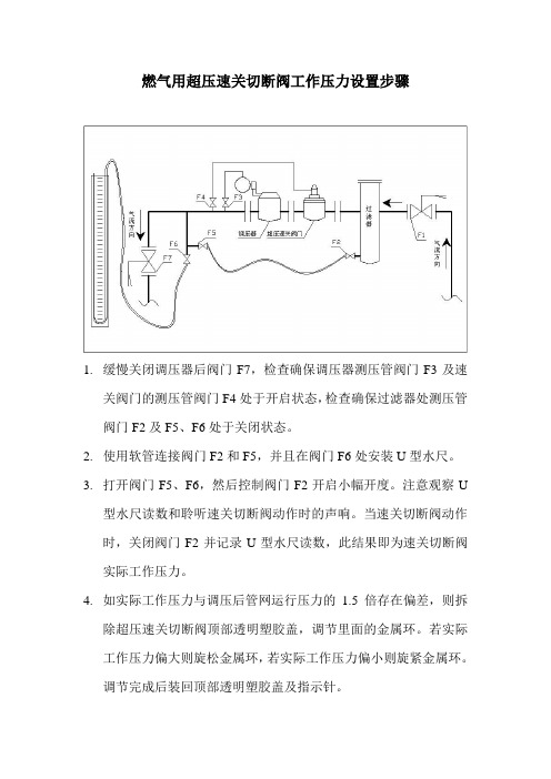
燃气用超压速关切断阀工作压力设置步骤
1.缓慢关闭调压器后阀门F7,检查确保调压器测压管阀门F3及速
关阀门的测压管阀门F4处于开启状态,检查确保过滤器处测压管阀门F2及F5、F6处于关闭状态。
2.使用软管连接阀门F2和F5,并且在阀门F6处安装U型水尺。
3.打开阀门F5、F6,然后控制阀门F2开启小幅开度。
注意观察U
型水尺读数和聆听速关切断阀动作时的声响。
当速关切断阀动作时,关闭阀门F2并记录U型水尺读数,此结果即为速关切断阀实际工作压力。
4.如实际工作压力与调压后管网运行压力的1.5倍存在偏差,则拆
除超压速关切断阀顶部透明塑胶盖,调节里面的金属环。
若实际工作压力偏大则旋松金属环,若实际工作压力偏小则旋紧金属环。
调节完成后装回顶部透明塑胶盖及指示针。
5.把速关阀门复位手柄往内压,并逆时针方向旋转手柄,对超压速
关阀门进行复位。
如复位成功则顶部透明塑胶盖内指示针会下落,并且能听到过气的声音。
6.重复步骤3、4、5,直至实际工作压力等于调压后管网运行压力
的1.5倍。
7.关闭阀门F2、F5、F6,拆除F2、F5间的连接软管,拆除F6处的
U型水尺。
缓慢打开阀门F7开始供气。
超压速关切断阀工作压力设置完成。
进口燃气调压阀主要参数
进口燃气调压阀主要参数进口燃气调压阀是一种用于控制燃气供应压力的重要设备。
它具有多项关键参数,对于燃气供应系统的稳定运行至关重要。
下面将对进口燃气调压阀的主要参数进行详细介绍。
进口燃气调压阀的额定压力是指阀门能够承受的最大压力。
这个参数很重要,因为它决定了阀门的工作范围。
如果额定压力过高,阀门可能无法正常工作,导致燃气压力过大,甚至造成设备损坏或安全事故。
相反,如果额定压力过低,阀门可能无法满足系统的需求,导致燃气供应不稳定。
进口燃气调压阀的流量系数是指阀门通过燃气的能力。
它是根据阀门的结构和开启程度计算出来的,通常以 Cv 值表示。
流量系数越大,阀门通过燃气的能力越强,反之则越弱。
选择适合的流量系数可以确保燃气供应系统能够满足实际需求,避免供应不足或浪费。
进口燃气调压阀的响应时间也是一个重要参数。
响应时间是指阀门从接收到信号到实际调节燃气压力的时间间隔。
较短的响应时间可以保证燃气供应系统对于负荷变化的快速响应,从而保持燃气压力的稳定性。
进口燃气调压阀的关闭压力差也需要考虑。
关闭压力差是指阀门关闭时需要克服的最大压力差。
如果关闭压力差过大,阀门在关闭时会产生较大的冲击力,可能导致设备损坏或噪音过大。
进口燃气调压阀的材质和密封性能也是需要重视的参数。
阀门的材质应能适应燃气的特性,具有良好的耐腐蚀性和耐高温性。
同时,阀门的密封性能决定了阀门是否能够有效地控制燃气压力,避免泄漏。
进口燃气调压阀的主要参数包括额定压力、流量系数、响应时间、关闭压力差、材质和密封性能。
这些参数对于燃气供应系统的正常运行和安全性至关重要,合理选择和配置燃气调压阀可以确保系统的稳定性和可靠性。
自力式压力调节阀使用说明书(已配图)

(用于阀后调节),或泄压、稳压(用于阀前调节)的自
动控制。
二、结构与作用原理
调压阀主要由检测执行机构、调节阀、冷凝器与阀后 接管等四部分组成,其结构详见图一。
图 一 a、 用 于 控 制 阀 后 压 力 的 调 节 阀 , 阀 的 作 用 方 式
为压闭型。其原理如下:介质由箭头方向流入阀体,经阀 芯、阀座节流后输出。另一路经冷凝器(介质为蒸汽时使
1.25
2、压力调节范围确定 压力调节范围分段,详见主要参数及性能指标表一, 控制压力应尽量选取在调节范围的中间值附近(见表一)
3、阀后压力调节阀,其阀前压力与阀后压力的关系 自力式调节阀本身是一个调节系统,阀本身又有一定 的压降要求,对阀后压力调节阀(B型),为保证阀后压力在
一定范围内,其阀前压力必须达到一定值,其要求可参见表二。
阀前压力kpa 650 700 750 800 850 900 950 1000 1250 1500 2000 2500 3000
阀后压力kpa
65~ 70~ 75~ 80~ 85~ 90~ 95~ 100~ 125~ 150~ 200~ 250~ 300~ 520 560 600 640 680 720 760 800 1000 1200 1600 2000 2400
3
表二
阀前压力kpa 30 50 100 150 200 250 300 350 400 450 500 550 600
阀后压力kpa
15~ 15~ 15~ 15~ 20~ 25~ 30~ 35~ 40~ 45~ 50~ 55~ 60~ 24 40 80 120 160 200 240 280 320 360 400 440 480
升到设定值为止。
图 一 b、 用 于 控 制 阀 前 压 力 的 调 节 阀 , 阀 的 作 用 方 式
燃气电磁阀说明书
低压系列防爆手开电关燃气安全切断阀本系列电磁阀属一种低压(9-12V燃气紧急切断阀,因其具有优良的技术性能,压阻小及高可靠性,适用于天燃气、城市煤气、液化石油气等多种可燃气体,广泛用于供气管网控制系统,燃气锅炉房等安全防范系统。
如与可燃气体泄漏监测装置配套连接,当仪器检测到可燃气体泄漏时,能自动快速的切断供气阀门的气源供给防止恶性事故的发生。
本系列产品是一种常开式的脉冲触发式防爆电磁阀。
其在正常工作中处于常开位置,此时电磁阀处于断电状态,也不消耗电能,当事故发生时,阀门线圈瞬时通电并能触发阀门的快速关闭,随即进入自锁状态。
此时即使撤去电源,阀门仍处自锁关闭状态,不会出现重新自动打开现象,只有待操作人员处理完事故,才能人工重新开启阀门恢复供气。
工作原理:手动拉杆向上拉动使阀门处于打开状态,当电磁铁通电时(电时间≤3秒),动铁芯向上吸动,滑动珠处于放松状态,手动拉杆推动支撑,在弹簧的作用下迅速向下滑动,带动膜片封闭阀口,电磁阀关闭。
如需打开,将手动拉杆拉至定位位置时,拉杆自动定位保持常开。
一、安装使用注意事项1、安装时应选择振动较小的水平管道段为宜,阀必须直立,线圈朝上,倾斜度不允许超过15%,否则不能保证密封。
2、电磁阀铭牌上的参数应与实际使用要求相符。
3、电磁阀阀体上的箭头应与介质流向一致。
为保证电磁阀的正常使用,请在阀前加装燃气专用过滤器。
5、本阀自身不具防爆性能,若环境因素易引发可能发生的爆炸,请选用防爆型燃气电磁阀,并在订货时提出。
6、安装前请彻底吹扫管道,以避免异物损伤膜片造成电磁阀失灵。
7、当电磁阀发生故障时,为了及时隔离和便于维修,建议安装旁通(旁路)装置。
8、使用中若阀启闭失灵,可检查线圈是否断电;使用电源及介质压力是否正常。
9、若阀有较严重的内外泄漏,可检查各密封垫是否破损;锁昆螺母是否松动等。
10、电磁阀暂不安装时,可存放在0~40℃,相对湿度≤80%无腐蚀气体的室内,不允许露天存放。
燃气调压装置使用说明书

西气东输-平舞漯地方支线工程燃气调压装置使用说明书尊敬的用户:感谢您选用费希尔久安燃气调压装置,为保证燃气调压装置安全工作和设备正常供气,安装操作前请仔细阅读本说明书以及各单体设备使用说明书的有关内容。
说明书应妥善保存,以备查询。
费希尔久安输配设备(成都)有限公司Fisher Jeon Gas Equipment (Chengdu) Co.,Ltd目录1概述 (3)2主要参数 (4)2.1各站主要参数 (4)2.2型号说明 (5)3燃气调压装置的安装程序 (6)4燃气调压装置的运行与调试 (7)4.1空气置换 (7)4.2运行前的准备及注意事项 (8)4.3气密性试验 (9)4.4调试运行程序 (10)4.5调压器参数设定 (12)4.6工作管路与备用管路的人工切换方法 (14)4.7停机的操作程序 (15)5常见故障分析与排除 (16)6燃气调压装置的维修保养 (18)6.1检修周期及维修程序 (19)6.2维护保养中的注意事项 (21)7尺寸,重量及吊装 (22)7.1设备尺寸及重量 (22)7.2设备吊装 (22)8售后服务 (23)1概述(燃气调压装置是在城镇燃气输配系统中,专为城市门站、分输站、储配站、燃气轮机、燃气锅炉、燃气发电厂或其他大型专用用户设计的成套调压设备。
通常具有接收气源来气、燃气净化、燃气调压、气量分配、计量、安全保护等功能;采用整体橇装形式,所有功能模块集成于一个或多个撬座上。
根据工程条件和系统需要,还可增设消音设备、加热设备、监控及数据采集设备、加臭装置、清管设备等功能模块。
具有安全性好、可靠性高、经济性能良好、占地面积小、内部结构优化合理、安装调试简单、测试维修方便等特点。
本燃气调压装置按照我国现行国家标准GB50028《城镇燃气设计规范》及我公司企业标准Q/76227017-0.1-2006《撬装式城镇燃气调压装置》执行。
)本说明书主要介绍燃气调压装置的主要参数、结构特点、主要设备、安装运行调试方法、故障处理、维修保养等内容。
燃气调压站操作规程完整精选全文
可编辑修改精选全文完整版调压站操作规程1、所有经过验收合格,投入运行的调压站均应达到要求,并定期进行维护保养工作;2、平时在调压站的操作中应注意以下事项,以保证调压器的正常使用和减少故障:2.1切忌快速开启阀门,猛开阀门,极易损坏调压站设备;2.2切忌向出口管道充入过高压力,否则会损坏调压站内部零件;3、开启投入运行调压站时,应按下述步骤操作:3.1确认调压站的进出口阀门已关闭;3.2缓慢开启进口阀门,并观察进站压力表和出站压力表是否在允许的范围内,为避免出口压力表在充气时超量程损坏,可先关闭压力表下阀门,待压力稳定后再充分开启;3.3打开调压站后直管上的测压嘴,检查调压器的运行是否正常;3.4当进出口压力正常后,可慢慢开启出口阀门,并精确调压器的出口压力;4、调压站切断阀的复位操作:4.1在进行复位操作前应查明切断的原因;4.2排除故障后,方可进行复位操作;4.3在进行切断阀的操作时,应关闭站内进出口和压力表下阀门;4.4在转动人工复位手柄时,注意缓慢进行;4.5缓慢开启进口阀门,观察出口压力,正常后开启出口阀门。
CNG槽车加气操作规程G槽车进站前,槽车与车头电源摘除,后由操作工引导停放在指定位置,槽车与车头必须摘开,槽车头位悬挂“正在加气”警示牌。
2.检查CNG槽车阀门各接口处是否完好。
3.连接接地装置。
将加气软管与CNG槽车连接好并用钢丝卡子固定。
4.注意:装、卸加气软管时要侧身,不要正对快装接头。
5.打开CNG槽车进出气阀门,打开放空阀门,利用车内余压将软管内空气排净。
6.关闭放空阀门,缓慢打开加气柱阀门,开始加气。
7.加气过程中,30分钟巡查一次,观察有无漏气及其它异常现象。
8.当车内压力充至到20MPa时,关闭加气柱阀门,关闭CNG槽车进出气阀门及各瓶阀门。
9.打开放空阀门,将软管内气体放净。
10.先将加气软管卸下,再将钢丝卡子和接地装置拆下后摆放好,摘下“正在加气”警示牌,加气完毕。
- 1、下载文档前请自行甄别文档内容的完整性,平台不提供额外的编辑、内容补充、找答案等附加服务。
- 2、"仅部分预览"的文档,不可在线预览部分如存在完整性等问题,可反馈申请退款(可完整预览的文档不适用该条件!)。
- 3、如文档侵犯您的权益,请联系客服反馈,我们会尽快为您处理(人工客服工作时间:9:00-18:30)。
June 2010
Type R622 Pressure Reducing Regulator
• Compact Design • Protective Inlet Screen • High Capacity • Internal Relief • Light Weight
upper spring case relief valve spring DIAPHRAGM
valve disk
INLET PRESSURE INLET PRESSURE ATMOSPHERIC PRESSURE OUTLET PRESSURE OUTLET PRESSURE OUTLET PRESSURE ATMOSPHERIC PRESSURE INLET PRESSURE ATMOSPHERIC PRESSURE
Figure 2. Type R622 Operational Schematic
M1027
orifice
stem
lever PUSHER POST
Principle of Operation
Refer to Figure 2. When downstream demand decreases, the pressure under the diaphragm increases. This pressure overcomes the regulator setting (which is set by the control spring). Through the action of the pusher post assembly, lever, and valve stem, the valve disk moves closer to the orifice and reduces gas flow. If demand downstream increases, pressure under the diaphragm decreases. Spring force pushes the pusher post assembly downward and the valve disk moves away from the orifice allowing flow through the body to the downstream system. Type R622 regulators include an internal relief valve for overpressure protection.
W8806
• Inlet and Outlet Pressure Gauge aps
Figure 1. Type R622 Pressure Reducing Regulator
Introduction
Type R622 direct-operated, spring-loaded regulators provide economical pressure reducing control in a variety of residential, commercial, and industrial applications. These regulators can be used with natural, manufactured, or propane gases and have the same inlet and outlet pressure capabilities.
D103094X012
Bulletin 71.1:R622
Specifications
Body Size and End Connection Style(1) 1/2 NPT inlet and outlet Maximum Allowable Inlet Pressure(1) Operating: 125 psig (8,6 bar) Emergency: 125 psig (8,6 bar) Except 1.8 to 2.2-inches w.c. (4 to 5 mbar) spring range which has operating and emergency pressures of 60 psig (4,1 bar) Maximum Allowable Outlet (Casing) Pressure(1) Operating to Avoid Internal Part Damage: 3 psid (0,21 bar d) above outlet pressure setting Emergency: 20 psi (1,4 bar) Outlet Pressure Ranges See Table 1 Orifice Size 1/8-inch (3,2 mm) orifice Flow Coefficients Wide-Open Cg for Relief Sizing: 12.5 Wide-Open Cv for Relief Sizing: 0.36 C1: 35 IEC Sizing Coefficients XT: 0.78 FD: 0.82 FL: 0.89 Flow Capacities See Table 2 Pressure Registration Internal Relief Performance See Figure 4 Internal Relief Performance Start-to-Discharge is 8 to 22-inches w.c. (20 to 55 mbar) for setpoints from 1.8 to 20-inches w.c. (4 to 50 mbar) Start-to-Discharge is 140 to 200% over setpoint from 20-inches w.c. to 2.2 psig (50 to 152 mbar) Spring Case Vent Connections 3/4 NPT with removable screen Temperature Capabilities(1) -20° to 160°F (-29° to 71°C) Approximate Weight 2.35 pounds (1 kg) Construction Materials Body, Spring Case, Diaphragm Plate, and Orifice: Aluminum Diaphragm, Disk, and O-ring: Nitrile (NBR) Adjusting Screw and Pushpost: Delrin® Closing Cap: ASA Thermoplastic (UV-Ray Resistant) Control Spring: Zinc-plated steel Machine Screw, Spring Seat, and Lever: Zinc-plated steel Valve Stem: Zinc Relief Valve Spring, Relief Spring Retainer, Lever Pin, and Vent Screen: Stainless steel
SPRING FREE LENGTH, INCHES (mm) 3.40 (86,4) 3.40 (86,4) 3.61 (91,7) 4.10 (104) 3.60 (91,4) 3.52 (89,4) 3.66 (93,0)
2
Bulletin 71.1:R622
control (Main) spring
Table 1. Outlet Pressure Ranges
OUTLET PRESSURE RANGE 1.8 to 2.2-inches w.c. 5 to 7-inches w.c. 6.5 to 9-inches w.c. 9 to 13-inches w.c. 13 to 20-inches w.c. 16 to 35-inches w.c. 1 to 2.2 psig (4 to 5 mbar) (12 to 17 mbar) (16 to 22 mbar) (22 to 32 mbar) (32 to 50 mbar) (40 to 87 mbar) (69 to 152 mbar)
Installation
Type R622 regulator may be installed in any position. However, the spring case vent should be pointed downward. If gas escaping through the Type R622 internal relief valve could constitute a hazard, the spring case vent must be piped to a location where escaping gas will not be hazardous. If the vented gas will be piped to another location, obstruction-free tubing or piping at least equal to the vent, and the end of the vent pipe must be protected from anything that might clog it. Dimensions are shown in Figure 5.
In addition, Type R622 regulators have internal relief across the diaphragm to help minimize overpressure. Any outlet pressure above the start-to-discharge point of the non-adjustable relief valve spring moves the diaphragm off of the relief valve seat, allowing excess pressure to bleed out through the screened spring case vent.
