HD100读写器说明书(新)
(整理)hd中文操作手册.
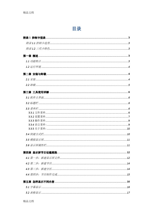
目录附录1 控制卡型录 (3)附录1.1控制卡选型 (3)附录1.2三代卡特色 (3)第一章概述 (3)1.1功能特点 (3)1.2运行环境 (4)第二章安装与卸载 (4)2.1安装 (4)2.2卸载 (5)第三章工具使用详解 (6)3.1软件主界面 (6)3.2标题栏 (6)3.3菜单栏 (6)3.3.1文件菜单 (6)3.3.2设置菜单 (7)3.3.3操作菜单 (9)3.3.4语言菜单: (9)3.3.5关于菜单: (10)3.4快捷方式栏 (10)3.5模拟显示屏 (11)3.6显示屏属性栏 (11)第四章显示屏节目创建流程 (12)4.1第一步:新建显示屏文件 (12)4.2第二步:新建节目 (14)4.3第三步:新建分区 (14)4.4第四步:节目制作完成 (15)第五章怎样显示不同内容 (16)5.1字幕显示 (16)5.2表格显示 (17)5.3图文显示 (18)5.4时间显示(万年历时间) (18)5.5表盘显示(模拟时钟) (19)5.5顺/倒时计显示 (20)5.6温度显示(需另购感应器) (21)第六章通信设置 (22)6.1串口线的做法 (22)6.2通信设置(串口) (23)6.3网线的做法 (24)6.4通信设置(网口) (25)6.4.1局域网单网络卡(HD-E3)通信 (25)6.4.2局域网多个网络卡(数个HD-E3)通信 (25)6.4.3局域网多个网络卡设置视频 (27)附录2 使用过程中的常用设置 (28)附录2.1控制卡如何远程升级 (28)附录2.2控制卡如何恢复出厂设置 (28)附录2.3控制卡如何测试显示屏 (29)附录2.4显示屏定时开关机 (30)附录2.5显示屏指定时间播放 (30)附录2.6字幕静止不动应该怎么设置 (30)附录1 控制卡型录附录1.1控制卡选型1:HD-S3-串口卡,控制范围32*1024(64个P10模组);2:HD-M3-串口卡,控制范围64*768/32*1536(96个P10模组);3:HD-Q3-U盘卡,控制范围64*768/32*1536(96个P10模组);4:HD-E3-网络卡,控制范围128*768/64*1536(192个P10模组);5:HD-U3-U盘卡,控制范围128*1280/64*2048(256个P10模组);6:HD-X3-U盘卡,控制范围256*1024/128*2048(512个P10模组);7:HD-G3-U盘卡,控制范围512*800/128*3072(800个P10模组);以上控制范围均为单色情况下,双色控制长度减半附录1.2三代卡特色采用全新高速32位MCU、扩大控制范围、性价比更高第一章概述1.1功能特点《HD2011》控制系统是2011年灰度科技有限公司应对条屏市场做出的较大的一次调整。
BU100蓝牙超高频读写器操作说明

BU100蓝牙超高频读写器操作说明BU100蓝牙超高频读写器操作说明V1.00目录目录 (1)1开机操作 (2)2关机操作 (2)3按键读卡操作 (2)4上传存储卡号 (3)5透传模式 (8)6固件升级 (9)1开机操作长按开/关机键(约3S),即可开机,开机欢迎界面如下图所示。
2关机操作在欢迎界面、设置界面或读卡结果显示界面下,长按开/关机键(约3S),即可关机;在上述界面下30S内无按键动作,读写器将自动关机。
3按键读卡操作读写器靠近标签,在开机欢迎界面下,短按向上方向键,使屏幕下方的功能指示三角指向扫描项,然后短按确认键,启动读卡。
读卡界面如下图所示。
在读卡过程中短按开/关机键或确认键会取消读卡,退回到开机欢迎界面。
读到卡号后,屏幕会显示卡号,读取结果显示界面如下图所示。
通过上下方向键选择扫描项或返回项,然后短按确认键可以启动第二次读卡或退回开机欢迎界面。
4上传存储卡号打开手机端获取存储卡号的APP软件(BTUHF_Reader),界面如下图所示。
首先选择“连接/断开”,进入蓝牙连接界面,如下图所示。
然后选择“未配对设备”,进入蓝牙搜索界面,如下图所示。
搜索到蓝牙读写器设备后,如下图所示。
选择蓝牙读写器设备,点“确定”进行连接,如下图所示。
首次选择要根据提示输入密码,默认密码为1234。
即可完成配对连接。
如下图所示。
蓝牙连接成功后,BU100端界面多出一个蓝牙连接的图标,界面如下图所示。
在软件主界面上,选择“上传卡号”,进入“上传卡号”界面,如下图所示。
入设置菜单,显示界面如下图所示。
据。
此时手机端就会收到存储的卡号,显示界面如下图所示。
5透传模式首先在主界面上选择配对蓝牙连接成功后,在BU100读写器端的开机欢迎界面下短按向下方向键,使屏幕下方的功能指示三角指向设置项,然后短按确认键,进入设置菜单,显示界面如下图所示。
通过上下方向键选择第二个选项“透传模式”,然后短按确认键,进入透传模式,即可通过手机端软件直接控制BU100读写器的RFID模块(详细使用方法请参考BU100超高频蓝牙读写器使用手册),透传模式下BU100的显示界面如下图所示。
D100使用说明书
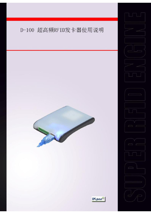
目录一、认识您的读写器 (3)1.1前视图 (3)1.2后视图 (3)1.3俯视图 (3)二、读写器的操作和设置 (4)2.1初次使用 (4)2.1.1 第一步:连接数据线 (4)2.1.2 第二步:用演示软件操作读写器 (5)2.2射频参数设置 (7)2.2.1设置射频输出功率 (7)2.3 盘存ISO-18000-6C标签 (7)2.3.1缓存模式和实时模式 (7)2.4存取 ISO-18000-6C标签 (12)2.4.1读标签操作 (12)2.4.2写标签操作 (13)2.4.3锁定标签操作 (14)2.4.4灭活标签操作 (14)2.4.5选定操作的标签 (15)三、开发自己的RFID应用程序 (16)四、安装驱动 (17)一、认识您的读写器1.1前视图1.2后视图1.3俯视图二、读写器的操作和设置2.1初次使用2.1.1 第一步:连接数据线通过USB数据线与电脑连接,如图:此时,需要将配置开关切换到如下图所示位置:也可以通过串口与电脑相连,如图:此时,需要将配置开关切换到如下图所示位置:连接好读写器的同时,将听到“滴”的一声鸣响,同时指示灯亮。
表示上电过程正常,读写器自检通过。
注:读写器首次与PC连接会自动安装驱动。
如过驱动安装失败,可以到我司网站下载驱动并手动安装。
(安装方法详见:第15页“安装驱动”)2.1.2 第二步:用演示软件操作读写器启动随机附带的演示软件。
此软件不需要安装,直接将 UHFDemo.exe , reader.dll, customControl.dll 三个文件拷贝至同一个文件夹,并双击可执行文件 UHFDemo.exe 即可。
软件启动后界面如图所示:选择对应的串口号(查看串口号:我的电脑-管理-设备管理器-端口-USB Serial Port),然后单击“连接读写器”按钮,若串口没有被占用,在下方的操作记录栏里会显示如下信息:单击读取版本号按钮,界面将显示相应的信息,如下图所示:此时,读写器与电脑的连接已成功完成。
UHF读写器用户手册说明书

UHF Reader User Manual2E-26562E-2657Contents1. Model Parameter: (3)2. Model Package: (3)3. Wiring Diagram: (4)3.1 Example with Anson Controller (5)3.2 Connect to Ground: (5)4. Installation: (5)4.1 Installation 1 example: (6)4.2 Mounting reader and height adjustment (6)4.3 Reader Installation Angle Adjustment (7)4.4 Installation Example-Parking Lot (7)4.5 Tag position in vehicle (8)5. Application: (9)6. Quick Start for Software (9)6.1 Connect reader With PC (9)6.1.1 RS232 Communication (10)6.1.2 TCP/IP Communication (10)6.2 Basic Settings: (12)6.2.1 Wiegand Parameter Input Zone: (12)6.2.2 Basic Parameters Input Zone: (12)6.2.3 Freq Parameters Input Zone: (14)6.2.4 Senior Parameter Input Zone: (14)6.2.5 Active Encrypt Function (14)6.2.6 . Get Parameter (17)6.2.7 Set Parameter (17)6.2.8 Default All (17)6.2.9 Net Initialize (17)6.3.10 WIFI Initialize (17)6.3 Senior Settings (17)6.4 EPC Read and Write (18)6.5 ISO1800-6B Read and Write (19)7. Notice (20)1. Model Parameter:2. Model Package:In the package include one reader, 1 RS232 Serial port , 12V adapter and the antenna bearer. When you open the box, please check the spare parts, if with any question, please contact distributor or sales department.See below picture for the inside package and separate products picture(2E -2656).RS232/485 RS232/4851-15mDescription PictureDeviceRS232 Serial PortCable12V AdapterAntenna Bearer3. Wiring Diagram:Description Model Wire No. Color Function1 Red DC9-15Positive 2E-2656/57V2 Black GND Negative 2E-2656/573.1 Example with Anson Controller3.2 Connect to Ground:In case you use the external power supply for the UHF reader, then you must have acommon ground with controller, or will cause unknown problems.4. Installation:In general there are two installation ways of UHF reader, see blow picture 1 and 2.7 2E-2656/572E-2656/57PIN58 Grey Trigger/ 2E-2656/57 9 Orange 485+ / 2E-2656/57 10 Purple 485-/ 2E-2656/57TCP/IP UHF reader without Grey, orange and purple cable. 4 Green Data0 Wiegand D0 5 Yellow TXD RS232 PIN26BrownRXDRS232 PIN32E-2656/577 Blue GND RS232 GND 3 White Data1 Wiegand D12E-2656/572E-2656/57(1) (2)Installation 1 will be easy for installation, but distance will be less than installation 2, installation 2 will be more difficult for installation.4.1 Installation 1 example:4.2 Mounting reader and height adjustmentFor installation 1, the mounting pole diameter should be 50-60mm, height should be 2.2m, we suggest to use the stainless steel material(thickness greater than 1.2mm), use the bearer inside the reader box to fix into pole top, and adjust the height from reader center position to road according to vehicle type, in general the height is 1.8-2.2m.For installation 2,the L type mounting pole diameter should be 60-80mm, the cross beam diameter should be 50-60mmmm, and we suggest to use the stainless steel material(thickness should be 1.2mm-2mm).Use the bearer inside the reader box to fix into pole top and adjust the height from reader center position to road according to vehicle type, in general the height is 3.5-4m.4.3 Reader Installation Angle AdjustmentSee below picture 3 and 4 for reference adjust angle for reader.3 44.4 Installation Example-Parking LotPrincipal to install the reader:(1)Reader and barrier gate linear distance no go across 1m.(2)Between reader and tag, no items covered.(3)Distance between reader and control panel or PC distance we suggest as closer as possible and install shielded communication cable.(4)For detailed installation please according to real situation.Reader close to barrier, and make sure the sensing area can cover the ground sensor,See below picture.4.5 Tag position in vehicleIn general, the parking devices are installed in the left side of the lane, then the tag should be stick in the position of below picture showed.For small vehicle, we suggest A, B and C position, for big truck or big bus, we suggest D, E and F position. The principal of the tagposition is not cover the eyesight of driver.Suggest Position: If reader install in left side, then suggest A and E position. If reader install in the top, then suggest B and F, if reader install in right side, then we suggest C and D position.Tag installation when vehicle windshield with metal UV film:(1) Original UV film: According to European standard, Position B willreserve2E-2656 is 1-6m, 2E-2657 is 1-15m. And the vehicle speed should less than 15km/h.120m*70mm space(no contain metal) for RFID stickers. When install the tag, just install in the B position.(2)Self-stick UV film: Cut a space 120*70mmm special for RFID stickers.We suggest B,D or E position.(3) Use anti-metal tags, install in the car license plate.(4) Manual hold the RFID card to read.Correct Hold Card Wrong Hold Card5. Application:(1) Transport Control:(2) Vehicle Management(3) Parking Management(4) Access Control Management(5) Product Anti-fake Detection(6) Anti-thief Management6. Quick Start for SoftwareThe UHF reader with software to read and write the tags and cards, as well to adjust the basic parameter of the reader.6.1 Connect reader With PCThere are two mode of reader, one is TCP/IP and RS232 communication, the other is RS232 communication only.6.1.1 RS232 CommunicationThere are two client in software package, on is RFIDDemo3203.exe other is Netconfig.exe. For RS232 communication device, just open RFIDDemo3203.exe client.See below.Please ensure serial port of reader connect with PC, and select correct port in PC, then select baud rate, then click connect.6.1.2 TCP/IP CommunicationFor TCP/IP communication, you need open two client, Netconfig.exe and RFIDDemo3203.exe. Netconfig.exe to get the IP address and port of connected UHF reader. You can open it by click broadcast.1.See blow procedure 1, click broadcast to get the IP of uhf reader.2.And input the detected IP, but make sure that your pc and the address at the same LAN, be simple, you can ping the IP, see procedure 2.3.Then click “Connect” to connect the reader.4. If communication OK, see below6.2 Basic Settings:6.2.1 Wiegand Parameter Input Zone:It is mainly related to Wiegand output interface. Only communication mode is Wiegand26 or Wiegand34 available.Byte Offset:The byte of card number to be offset, there is a initial position when read card number. To change the initial position, for example Wiegand 26,output 3 byte, but 18600-6B card number (E0 01 02 03 04 05 06 07) i s 8 byte, the parameter is this 3 byte, when the value is 0, it is (E0 01 02), when the value is 1, It is (01 02 03)... More details, please refer to Wiegand protocol.Output Period: It is frequency of Wiegand port. More details, please refer to Wiegand protocol. Pulse Width: It is the time length of Wiegand signal.Pulse Period: It is interval time that from first low pulse to next low pulse sending. For details, please refer to Wiegand protocol.Note: In general, user only need set byte offset, other setup is default.6.2.2 Basic Parameters Input Zone:Work Mode:It includes 3 items:Active , Passive and Response modeActive: Reader keep reading card, and transmit each of card number by communication port (apply to active upload data).Passive: Reader keep reading card, and each of card number store in reader, but do not upload card number,the max. storage is 100pcs (apply to passive upload). 3. Response: Reader do not read card, reader response according difference commands. For example, PC send a recognize card command, reader will read a time and reply card number to PC (apply to short distance read and write card, test).Output Mode:It includes RS232, TCPIP, CANBUS, Wiegand26 and Wiegand34.RS232: Serial port communication mode, It connects with PC serial port directly and point to point mode.TCPIP:Network communication mode, it communicate with PC by LAN or WAN. CANBUS:BUS communication mode, it is point to multiple mode.Wiegand26:It is standard reader communication mode, one-way communication mode. Wiegand34 :It is standard reader communication mode, one-way communication mode.Read Interval:The speed of reading card.Note: read card interval must more than 10ms. If read card interval is too short, it will short lift of the reader.Power Size: The max. value is 30.Trigger:1. Close: Close trigger mode to read card.2. Low Trigger: When trigger lead (gray wire) connect with low power (OV), reader power on, when trigger lead (gray wire) connect with high power (12V), reader power off.Note: When Trigger mode is Close, trigger lead must connect with high power or low power and can not be dangling.Same ID Interval:When reader read a same card continuously, reader only upload one data. The read interval can be set at here, and if the read time is over set interval, reader will upload continuously. Buzzer: When reader read card, the buzzer beep or not.Buzzer:It includes disable and enable, disable mean turn off the buzzer, when read card, no beep, enable mean turn on the buzzer, when read card, with beep.Card Type:1. ISO18000-6B:Only read ISO18000-6B protocol tag.;2. EPC (GEN 2 )Single – Tag :Only read EPC(GEN 2)protocol tag, read one tag one time. Reader hard to or not read multiple tags when put them in the effective range.3. EPC (GEN 2 )Multi – Tag:Only reader EPC (GEN 2 )protocol tag, multi-tag can be read.4. EPC (GEN2 )Multi –Data:Only read EPC (GEN 2 )protocol tag,except read default EPC area 12 bytes data, other area data can be read. (Select this type and set to read the length of other area data in senior parameter, the max. Is 12 bytes)5. ISO18000-6B + EPC (GEN 2 ): ISO18000-6B and EPC (GEN 2 )protocol tag can be read.Freq Parameters Input Zone It refer to 18000-6b and EPC card, normally hopping need be selected.6.2.3 Freq Parameters Input Zone:It refer to 18000-6b and EPC card, normally hopping need be selected.6.2.4 Senior Parameter Input Zone:It is used for multiple channel reader (split reader), integrative reader default is antenna 6.2.5 Active Encrypt FunctionFor this version software, the encrypt function is hided, to enable the encrypt function, please see below procedure.1) Press”F8” 5 Time s2) Choose then “Enabled”, and set password, then set Parameters [Set Para].3) Now, put the tag on the reader, the reader is not beep;4) Presses “Encrypt Tag”, until the reader beep, then enc rypt succeed;Note: when the encrypt tag, you can move the tag to accelerate the process of encryption;6.2.6 . Get ParameterClick “Get Para” button, parameter of the reader can be acquired. Acquire parameter succeed if display green in status bar; Acquire parameter failure if display red in status bar.(Do not read card when acquire parameter)6.2.7 Set ParameterWhen change parameter in demonstration area, click “Set Para” button, updated data will be set in currently reader. Setup succeed if display green in status bar; Setup failure if display red in status bar.6.2.8 Default AllClick “ Default All” button, basic parameter and senior parameter will recover to default. (Need to click “parameter setup”, updated parameter will be set in reader).6.2.9 Net InitializeNull6.3.10 WIFI InitializeNull6.3 Senior SettingsSenior settings is mainly setup the TCP/IP reader parameter, such as IP address, Syris config and time config etc.TCP/IP config: User can modify the TCP/IP uhf readerSYRIS Config: It is to set Syris SN and Syris ID.Time Config: It is to set reader time.Soft Config: In general can ignore the function, soft reset, is reset the device by software.6.4 EPC Read and WriteThe module is used to read and write the EPC card number. when you click the module, will show below picture interface.Identify:When click, the card in the reader Hex number will display here.Read: When click read, the related address and length Hex number will display, for example the card number is 01-02-03-04-05-06-08-09-10-11-12,Address 2, length 2: 01-02, length is 3, then 01-02-03Address 3., length 2:03-04Address 4, length 2: 05-06...Write: When click write, will write the related Hex to related address.For example the card number is 01-02-03-04-05-06-07-08-09-12-10Address is 2 and length is 2, and write 02-01 to the address, then the card no. Become 02-01-03-04-05-06-07-08-09-10-11-12If write to address 3 and the length is 2.Then card number become 01-02-02-01-05-06-08-09-10-11-126.5 ISO1800-6B Read and WriteFor this module is to read and write 1800-6B card number.Identify:When click, the card in the reader Hex number will display here.Read: When click read, the related address and length Hex number will display, for example the card number is E0-04-00-00-3F-0B-22-07-00-00-00-00,Address 0, length 2: E0-04, length is 3, then E0-04-00Address 1., length 2:04-00Address 2, length 2: 00-00...Write: When click write, will write the related Hex to related address.For example the card number is E0-04-00-00-3F-0B-22-07-00-00-00-00,Address is 0 and length is 2, and write 01-02 to the address, then the card no. Become 01-02-00-00-3F-0B-22-07-00-00-00-00,If write to address 1 and the length is 2.Then card number become E0-01-02-00-3F-0B-22-07-00-00-00-007. Notice1. When reader is working, the operator should away from reader 30cm to satisfy the FCC RF requirement.2. Reader must away from the high he strong magnetic field3. When reader use external power supply, must connect the common ground with the controller or the device you connect with.4. For the reader, we suggest 9-15v power supply, you’d better use the power supply we supply or appropriate voltage power supply.5. Mount the reader on a round pole or flat surface when you do installation.6. Connect all the wire as wiring diagram suggest.。
D-100系统用户手册说明书

As easy as A-1-cAutomatically re-testrejected resultsThe D-100™ system includes an onboard Advisor that providesa consistent, thorough review of every result . Normal resultsmay be released automatically, while flagged results are held forfurther review . The Advisor helps to ensure nothing is missedwhile dramatically reducing hands-on time .Work smarterThe D-100™ system delivers high-quality results quickly and efficiently . All consumables are RFID-tagged for fully automated traceability and convenience . And, when it comes time, you can replace reagents without stopping the run .Get more done10,000-testanalytical column with RFID tag 80 results/hourBe confidentThe D-100™ system generates gold-standard HPLC results every 45 seconds with variant detection and no interference from common variants . This means you can have complete confidence in your results .The future of A1c testing Ordering InformationCatalog No. Description290-1000 D-100™ Hemoglobin Testing System . . . . . . . . . . . . . . . . . . . . . . . . . . . . . . . . . . . . . . . . . . . . . . . .1 each 290-1004 D-100™ HbA 1c Analytical Cartridge/Calibrator Pack . . . . . . . . . . . . . . . . . . . . . . . . . . . . . . . . . . . . .1 each 290-1006 D-100™ HbA 1c Calibrator Pack . . . . . . . . . . . . . . . . . . . . . . . . . . . . . . . . . . . . . . . . . . . . . . . . . . . .1 each 290-1007 D-100™ Prefilters (5-pack) . . . . . . . . . . . . . . . . . . . . . . . . . . . . . . . . . . . . . . . . . . . . . . . . . . . . . . . .1 each290-1008 D-100™ Cleaning Tube. . . . . . . . . . . . . . . . . . . . . . . . . . . . . . . . . . . . . . . . . . . . . . . . . . . . . . . . . . .1 each 290-1009 D-100™ Sample Diluent, 1L . . . . . . . . . . . . . . . . . . . . . . . . . . . . . . . . . . . . . . . . . . . . . . . . . . . . . . .1 each 290-1010 D-100™ HbA 1c Elution Buffer A, 2600 mL . . . . . . . . . . . . . . . . . . . . . . . . . . . . . . . . . . . . . . . . . . . .1 each 290-1011 D-100™ HbA 1c Elution Buffer B, 1400 mL . . . . . . . . . . . . . . . . . . . . . . . . . . . . . . . . . . . . . . . . . . . .1 each290-1012 D-100™ Wash Solution, 3300 mL. . . . . . . . . . . . . . . . . . . . . . . . . . . . . . . . . . . . . . . . . . . . . . . . . . .1 each With over 30 years of experience in HPLC testing, Bio-Rad has developed the most advanced solution for A1c analysis . The D-100™ system simplifies high throughput A1c testing without sacrificing the high-quality results that are critical to patient care .Contact your Bio-Rad representative for a look at the future of A1c testing, today .Hemoglobin Interferences • No interference from hemoglobins S, C, D, and E • No interference from carbamylated Hb and labile HbA 1c • No interference from fetal Hb up to 30%Performance SpecificationsTotal Precision* . . . . . . . . . . . . . . . . . . . . . . . . . . . .≤1 .7% CV (NGSP units)Accuracy . . . . . . . . . . . . . . . . . . . . . . . . . . . . . . . . . . . . . . . . . . . . . . . . . .Total error < 6%Linear Range . . . . . . . . . . . . . . . . . . . . . . . . . . . . . . . . . . . . . . . . .3 .5 to 20% HbA 1cSample Concentration Range . . . . . . .50,000–350,000 mAUHbA 1c Units Reported . . . . . . . . . . . . . . . . . . . . . . . . . . . . .IFCC and NGSPFor further information, please contact the Bio-Rad office nearest you or visit our website at /diagnostics Clinical Diagnostics Group Web site /diagnostics USA 180****6723Australia 61 2 9914 2800 Austria 43 1 877 8901 Belgium 32 03 710 53 00 Brazil 55 31 3689 6600 Canada 151****4372China 86 21 61698500 Czech Republic 420 241 430 532 Denmark 45 4452 1000 Finland 358 9 804 22 00 France 33 1 47 95 60 00 Germany 49 0 89 318 840 Greece 30 210 7774396 Hong Kong 852 2789 3300 Hungary 36 1 459 6100 India 180****1224Israel 972 3 9636050 Italy 39 02 216091 Japan 81 3 6361 7070 Korea 82 2 3473 4460 Mexico 52 55 5488 7670 The Netherlands 31 318 540666 New Zealand 64 9 415 2280 Norway 47 23 38 41 30 Poland 48 22 3319999 Portugal 351 21 472-7700 Russia 7 495 721 1404 Singapore 65 6415 3170 South Africa 27 11 442 85 08 Spain 34 91 590 5200 Sweden 46 8 555 127 00 Switzerland 41 0 26 674 55 05 06 Taiwan 886 2 2578 7189 Thailand 662 651 8311 United Kingdom 44 0 20 8328 2000Bio-Rad Laboratories, Inc.© 2016 Bio-Rad Laboratories, Inc. Printed in USA DG16-0007 A-320 Rev. 02/2016Printed on recycled paperwith soy-based inks * Total precision is based on a 3-instrument, 60-day precision study using 3 lots of reagents to generate a total of 720 data points per sample . Itincludes the following sources of variation: within-run (repeatability), between-run, between-day, between-instrument, and between-lot .。
信捷电气以太网型可编程序控制器用户手册说明书
无锡信捷电气股份有限公司资料编号PD07 20210112 3.5信捷电气基于以太网的TCPIP通讯用户手册第一版目录———————————————————————以太网通讯概述———————————————————————以太网参数的配置———————————————————————接线方式及通讯协议———————————————————————以太网通讯指令———————————————————————1234基本说明♦感谢您购买了信捷以太网型可编程序控制器。
♦本手册主要介绍以太网型可编程序控制器的以太网通讯功能。
♦在使用产品之前,请仔细阅读本手册,并在充分理解手册内容的前提下,进行接线。
♦软件及编程方面的介绍,请查阅相关手册。
♦请将本手册交付给最终用户。
用户须知♦只有具备一定的电气知识的操作人员才可以对产品进行接线等其他操作,如有使用不明的地方,请咨询本公司的技术部门。
♦手册等其他技术资料中所列举的示例仅供用户理解、参考用,不保证一定动作。
♦将该产品与其他产品组合使用的时候,请确认是否符合有关规格、原则等。
♦使用该产品时,请自行确认是否符合要求以及安全,对于本产品故障而可能引发机器故障或损失时,请自行设置后备及安全功能。
责任申明♦手册中的内容虽然已经过仔细的核对,但差错难免,我们不能保证完全一致。
♦我们会经常检查手册中的内容,并在后续版本中进行更正,欢迎提出宝贵意见。
♦手册中所介绍的内容,如有变动,请谅解不另行通知。
联系方式如果您有关于本产品的使用问题,请与购买产品的代理商、办事处联系,也可以直接与信捷公司联系。
♦电话:400-885-0136♦传真:*************♦地址:无锡市滴翠路100号创意产业园7号楼4楼♦邮编:214072WUXI XINJE ELECTRIC CO., LTD. 版权所有未经明确的书面许可,不得复制、传翻或使用本资料及其中的内容,违者要对造成的损失承担责任。
读写器操作说明(实际操作应用)
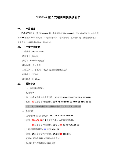
ZKR6806M嵌入式超高频模块说明书一、产品概述ZKR6806M是一款ZKR6806M是一款能够读写IS0-18000-6B,EPC CLASS1 G2协议标签的UHF频段的RFID读写器。
广泛应用于资产门禁安全管理、生产流水线、物流领域的追踪、追溯管理。
可以同时读写多个标签目标。
二、主要技术参数工作频率:902~928MHz通讯接口:RS232波特率:9600bps可配置读写功能:读写双工工作方式:广谱跳频(FHSS)或定频发射脉冲方式电源接口:5V/DC读写距离:5—25cm三、通讯协议(一)、读写器操作指令1、发送指令读EPC前4个字节的数据指令:A5 FF 0B BD 00 00 00 00 01 02 02 01 00 8D说明:8D这个字节为校验和。
8D=0-A5- 0B-BD-00-00-00-00-01-02-02-01-00注意:发送指令的校验和与返回指令的校验和计算方法不一样2、返回指令:读到电子标签的数据返回:E5 FF 06 BD 01 0A 96 50 68说明:01 0A 96 50这4个字节为电子标签的内的数据。
29这个字节为校验和。
68=0-E5-FF-06-BD-01-0A-96-50没有读到标签返回:E9 FF 03 BD 01 57说明:57这个字节为校验和。
57=0-E9-FF-03-BD-01返回E5开头的数据表示读取标签成功。
返回E9开头的数据表示读取失败。
四、软件操作说明(一)、参数设置设置软件使用说明1、打开读写器参数配置软件,选择正确的COM口,波特率(默认为9600 bps),站地址默认为任意站,点击“联机”,连接设备与电脑。
连接成功提示如下显示框。
2、功率设置选择“功率设置”菜单栏,再选择RF通道然后勾选中功率设置,点击“查询参数”,然后可在<功率设置>框后面点击倒三角设置天线功率。
本模块只用到RF通道1,所以只需要设置RF通道1的功率即可。
Multicom MUL-HDENC-C-100-NA 高清数字编码器用户手册说明书

MUL-HDENC-C-100-NA High Definition Digital EncoderUser ManualMulticom, Inc.1076 Florida Central Parkway, Longwood, FL 32750 April 2019 (Version 1p)This manual is intended solely for use by purchasers of Multicom, Inc. HD Digital Encoders and their qualified servicetechnicians. This document is the property of Multicom, Inc. and incorporates proprietary subject material and information. The use of all design, manufacture, reproduction, and all other rights regarding these contents in whole or part without Multicom, Inc. written consent is expressly prohibited. Multicom® and the Multicom logo are registered trademarks of Multicom, Inc.2Safety PrecautionsThe presence of this symbol is to alert the installer and user to the presence of uninsulated potentiallydangerous voltages within the product’s enclosure that may be of sufficient magnitude to produce a risk of electric shock.TO REDUCE THE RISK OF FIRE OR ELECTRIC SHOCK, DO NOT EXPOSE THIS DEVICE TO RAIN OR MOISTURE. DO NOT OPEN THE UNIT. REFER SERVICING TO QUALIFIED AUTHORIZED PERSONNEL ONLY.∙ DO NOT terminate, change or uninstall any wiring without first disconnecting the unit’s poweradapter from the device.∙ This device is supplied with the appropriately rated power supply. The use of any other power supplycould cause damage and invalidate the manufacturer’s warranty.∙ DO NOT connect the power cord to the device if the power cord or unit is damaged. ∙ DO NOT cut the power cord.∙ DO NOT plug the power cord into an AC outlet until all cables and connections to the device havebeen properly connected.∙ The device should be installed in an environment consistent with its operating temperaturespecifications. Placement next to heating devices and ducts is to be avoided as doing so may cause damage. The device should not be placed in areas of high humidity. ∙ DO NOT cover any of the device’s ventilation openings.∙ If the device has been in a cold environment allow it to warm to room temperature for at least 2 hoursbefore connecting to an AC outlet.IMPORTANT∙ ALWAYS remove any network/ethernet connection from the HD Encoder after configuring it toinsure its security and highest performance∙ Use high quality cables and connectors and insure all connections are tight∙ Test the coaxial cable RF output at the TV to insure the levels are well within the TV input range ∙ Use Google Chrome, Microsoft Edge, or Mozilla Firefox as the web browser when configuring theHD Encoder. Google Chrome is preferred.∙ During the web browser Admin Reboot process, use a new Google Chrome “Incognito Window” toeliminate caching-related confusion and issues.∙ The factory Default is for J.83B RF output. If ATSC output is desired (example: for LATAMinstallation) then the RF Setup Menu > Channel Type must be changed to ATSC, etc.The hardware and software product trademarks are the property of their respective owners, includingGoogle Chrome, Microsoft Edge, and Mozilla Firefox.1.0 HD Encoder IntroductionThe Multicom MUL-HDENC-C-100-NA is a High Definition Agile Digital Encoder/Modulator for North America (USA and Canada) used to convert a single unencrypted HDMI input of up to 1080i/1080p into a J.83B QAM 64/QAM 256 RF or ATSC (8VSB) output. The Multicom MUL-HDENC-C-100-NA is feature rich, very flexible, powerful, user friendly, and is easy to use for both Residential and Commercial applications. The high quality HD performance allows action packed movies and sports channels on any HDTV.FRONT VIEW:REAR VIEW:LCD DisplayReset (use pin/paperclip)Power LED UP ArrowDOWN Arrow OKRF OutputGain (Attenuation)HDMI Input LAN Port (Web Management Port)AC Adapter32.0 SpecificationsVideo / Audio InputHDMI 1.4Connectors SingleAudio Embedded PCMOutputQAMStandard J.83 Annex BATSC-8VSBConnector 1 x “F” FemaleRF Mode Normal / InvertedChannel Type J.83B: STD / HRC / IRC;ATSC-8VSBFrequency Range J.83 Annex B: 57 – 861 MHz(Ch2 – Ch135)ATSC-8VSB: 57-803 MHz(Ch2 to CH69)Interleaver I=128, J=1Output Level 38 dBmV Typical(With 20dB Range ManuallyAdjustable)Flatness Across FullBand± 2dB TypicalMER 39 dB TypicalConstellation (Output Bitrate) J.83 Annex B:64-QAM (26.970Mbps) / 256-QAM (38.810Mbps) ATSC-8VSB:8VSB (19.390Mbps)Output Impedance 75 ohmRF Output ReturnLoss10 dB TypicalVCN Auto (Major & Minor) /Manual (Major & Minor) /Manual (One Part) Video / Audio Encoding ProfileVideoVideo Codecs MPEG-2 VBRBitrate (Adjustable) J.83 Annex B:HD: 12.0 – 24.0 MbpsSD: 1.0 – 9.0 MbpsATSC-8VSB:HD: 12.0 - 18.0 MbpsSD: 1.0 – 9.0 Mbps Resolution Output Same as input except:1080p60 in, 1080p30 out1080p50 in, 1080p25 out1080p30 in, 1080p30 out1080i60 in, 1080p30 out1080i50 in, 1080p25 out1080i30 in, 1080p30 out AudioAudio Codecs MPEG1 Layer II / MPEG4 AAC GeneralLocal Monitoring LCDWeb GUI Supported Firefox, Chrome, Safari, Edge Password Protected GUI: User SettablePower Supply 12 VDC 1.5AConsumption 5 WattsOperationalTemperature0c - +55cStorage Temperature -20c - +70cDimensions 188mm x 130mm x 37.2mm Weight 0.95 kgLanguage English*Subject to change without notification43.0 HD Encoder Programming/SetupTo setup and program the MULTICOM HD Digital Encoder you can use either the device’s LCD Front Panel and buttons or the Web Interface. The programming of the settings is easiest by using the Web Interface in Section 3.3.3.1 Using the HD Encoder Front Panel:Press UP/DOWN ARROW buttons to scroll through the display information.Main Menu: Input information and Output Name >> Short and long name, BitrateMain Menu: VCN information >> VCN, Channel, and FrequencyMain Menu: Management IP >> IP Address3.2 Using the HD Encoder Front Panel for Setup:When the unit is powered up it will first go through an internal booting and short self-test and then be ready for operation or initial setup. The factory Default is for J.83B:STD output. If ATSC RF output is desired (example: for Mexico installation) then the RF Setup Menu > Channel Type must be changed to ATSC, etc.Press “OK” Button to enter the s etup MAIN MENU system.The front panel LCD password is: 0000Enter the password by adjusting each digit by using the UP/DOWN ARROW buttons –then press “OK” when the digit is correct. Press “OK” to enter Main Menu. For security purposes the HD Encoder will timeout and return to a password protected mode if no buttons are pressed for about 10 seconds. FRONT PANEL:Login:Press “OK” buttonEnter PasswordUse UP/DOWN arrows to change digit, Press OK to set it and go to next until all 4 digits are entered – the unit will now be in setup MAIN MENU. Pressing the UP/DOWN ARROWS will scroll through the menus/settings. Pressing the OK will select/execute the Menu Item or Setting.Press UP/DOWN ARROW to scroll through MAIN MENU and use OK to select a Menu:Main Menu: RF SetupMain Menu: Encoder SetupMain Menu: Network SetupMain Menu: Change PasswordMain Menu: Reset to DefaultMain Menu: Exit5#1. Press UP ARROW to scroll through RF SETUP MENU:RF Setup Menu: Channel Factory Default: J.83B:STD: CH 2→ Range 2 - 135RF Setup Menu: TSID Factory Default: 1RF Setup Menu: Regional Name Factory Default: USARF Setup Menu: RF Factory Default: NormalRF Setup Menu: Channel Type Factory Default: J.83B:STD →ATSC or J.83BRF Setup Menu: Constellation Factory Default: 256 QAMRF Setup Menu: Exit#2. Press UP ARROW to scroll through ENCODER SETUP MENU:Encoder Setup Menu: VCN Factory Default: 2.1Encoder Setup Menu: VCN Mode Factory Default: Auto(two-part) → VCN Notes below Encoder Setup Menu: Short Name Factory Default: DTV1 → Up to 7 CharEncoder Setup Menu: Long Name Factory Default: ATSC-DTV1 → Up to 16 CharEncoder Setup Menu: HD Bitrate Factory Default: 18Mbps → Range 12 – 24 Mbps Encoder Setup Menu: SD Bitrate Factory Default: 4Mbps → Range 1 – 9 Mbps Encoder Setup Menu: ProgramNumber Factory Default: 101 → Range 1 - 65534Encoder Setup Menu: Audio Output Factory Default: MPEG1 Layer 2 → Or MPEG4 AACEncoder Setup Menu: Source ID Factory Default: 101 → Range 1 - 65535Encoder Setup Menu: Exit#3. Press UP ARROW to scroll through NETWORK SETUP MENU:Network Setup Menu: Host Name Factory Default: HDENC-271616Network Setup Menu: IP Setup Factory Default: DHCP Disable → EnableFactory Default: IP Address: 192.168.1.9Factory Default: Subnet Mask: 255.255.255.0Factory Default: Default Gateway: 000.000.000.000Network Setup Menu: ExitNote that the HD Encoder will reboot after using the NETWORK SETUP MENU.#4. Press UP ARROW to MAIN MENU: CHANGE PASSWORD#5. Press UP ARROW to MAIN MENU:RESET TO DEFAULTNote that the HD Encoder will reboot after using the RESET TO DEFAULT MENU.#6. Press UP ARROW to MAIN MENU:EXITAfter Selecting the desired Menu – Change Parameter SettingsUse UP/DOWN arrows to move and select the desired parameter, Press OK to start editing the parameter using the UP/DOWN arrows. After changing the setting, pressing the OK will set the parameter.63.2.1 VCN RELATED NOTES:VCN is the Channel number to be shown by the TV. The VCN Modes which will be available depend on whether the output is selected as J.83B or as ATSC.VCN Mode: Auto (two-part) - VCN will be set based on the Channel output selected in “RF Output Menu: RF”.Example: Output Channel set to 2. VCN for device will be set at 2.1This is automatically set by the CH output set in the RF Setup section.VCN Mode (Manual two-part) - VCN Manual 2-part- will allow the installer to control VCN channel regardless of the CH/freq. selected on the RF Output Setup page of the device.Examples:RF CH VCN Channel57 55.1101 101.2VCN Mode: Manual (one-part) - Use ‘VCN (one part) Menu’ to set VCN channel.Example: VCN can be set to a range 1-999.VCN Mode (Manual one-part) -VCN Manual 1-part- will allow the installer to control VCN channel regardless of the CH/freq. selected on the Output Setup page of the device.Examples:RF CH VCN Channel57 2101 105134 13373.3 Using the HD Encoder Web Interface:3.3.1 Overview of the ProcessProduct Factory Default IP: 192.168.1.9 and with DHCP - Disabled1.Connect an Ethernet cable directly (no Cross Over cable required) to the Web ManagementPort on the rear panel of the HD Digital Encoder or connect the device’s Ethernet cable to anEthernet switch. Connect Ethernet Cable to your PC/Laptop.2.Modify your PC/Laptop IP address to static address 192.168.1.103.Enter ‘192.168.1.9’ into your web browser to access the Web Interface of the HD Encoder.4.Enter the Web Interface and make any required device changes.5.Save all changes as required and then reboot the device.6.Verify parameters have changed and then end your web session.As an alternative, the HD ENCODER static IP Address may be configured (or DHCP enabled) on the front panel and then the Web Browser can be used for all other configuration changes by using the IP Address which will be displayed on the LCD. BE VERY CAREFUL WHEN USING THE DEFAULT IP ADDRESS AND CONNECTING TO AN EXISTING NETWORK – THERE MAY BE CONFLICT WITH EXISTING INSTALLED HARDWARE – THIS MUST ALWAYS BE A VOIDED.3.3.2 Configuring∙Use Google Chrome, Microsoft Edge, or Mozilla Firefox as the web browser when configuring the HD Encoder. Google Chrome is preferred.∙During the web browser Admin Reboot process, use a new Google Chrome “Incognito Window” to eliminate caching-related confusion and issues.Step 1: LoginUse the PC web browser - type in the IP AddressStep 2: Web Interface Login and Password:Default User Name: adminDefault Password: Admin123IMPORTANT NOTE: Save all changes before leaving each setup page8Step 3: Overview TabView the current settings, MAC address, Firmware version, etc.The other tabs (Encoder Setup, RF Output Setup, Network Setup, and Administration) are used to change the HD Encoder settings and operating parameters.It is HIGHLY recommended that after all other tabs have been configured that the HD Encoder be rebooted using the REBOOT button on the ADMINISTRATION tab.910Step 4: Encoder Setup TabSelect the Encoder Setup tab to program desired parameters such as VCN settings, Bitrates, and more. Save changesThe ENCODER SETUP MENU: Encoder Setup Menu: VCN Factory Default: 2.1 Encoder Setup Menu: VCN Mode Factory Default: Auto(two-part) → VCN Notes below Encoder Setup Menu: Short Name Factory Default: DTV1 → Up to 7 Char Encoder Setup Menu: Long Name Factory Default: ATSC-DTV1 → Up to 16 Char Encoder Setup Menu: HD Bitrate Factory Default: 12Mbps → Range 12 – 24 Mbps Encoder Setup Menu: SD Bitrate Factory Default: 4Mbps → Range 1 – 9 Mbps Encoder Setup Menu: ProgramNumber Factory Default: 101 → Range 1 - 65534 Encoder Setup Menu: Audio Output Factory Default: MPEG1 Layer 2 → Or MPEG4 AAC Encoder Setup Menu: Source ID Factory Default: 101 →Range 1 - 65535VCN RELATED NOTES:VCN is the Channel number to be shown by the TV. The VCN Modes which will be available depend on whether the output is selected as J.83B QAM or as ATSC.VCN Mode: Auto (two-part) - VCN will be set based on the Channel output s elected in “RF Output Menu: RF”.Example: Output Channel set to 2. VCN for device will be set at 2.1This is automatically set by the CH output set in the RF Setup section.VCN Mode (Manual two-part) - VCN Manual 2-part- will allow the installer to control VCN channel regardless of the CH/freq. selected on the RF Output Setup page of the device.Examples:RF CH VCN Channel57 55.1101 101.2VCN Mode: Manual (one-part) - Use ‘VCN (one part) Menu’ to set VCN channel.Example: VCN can be set to a range 1-999.VCN Mode (Manual one-part) -VCN Manual 1-part- will allow the installer to control VCN channel regardless of the CH/freq. selected on the Output Setup page of the device.Examples:RF CH VCN Channel57 2101 105134 13311Step 5: RF Output Setup TabSelect any desired changes, including type of RF output: J.83B or ATSC.Save any changes made.The RF SETUP MENU:RF Setup Menu: TSID Factory Default: 1RF Setup Menu: Regional Name Factory Default: USARF Setup Menu: RF Factory Default: Normal → Or Inverted RF Setup Menu: Channel Type Factory Default: J.83B:STD →ATSC or J.83B RF Setup Menu: CH/Freq.Factory Default: J.83B:STD: CH2→ Range 2 - 135 RF Setup Menu: Constellation Factory Default: 256 QAMStep 6: Network Setup TabSet the IP Address, select static or dynamic IP (DHCP), etc.Save changes.12The NETWORK SETUP MENU:Network Setup Menu: Host Name Factory Default: HDENC-271616Network Setup Menu: IP Setup Factory Default: DHCP Disable → EnableFactory Default: IP Address: 192.168.1.9Factory Default: Subnet Mask: 255.255.255.0Factory Default: Default Gateway: 000.000.000.000 Step 7: AdministrationIt is HIGHLY recommended that after all other tabs have been configured that the HD Encoder be rebooted using the REBOOT button on the ADMINISTRATION tab.The HD Encoder can be reset to factory default using this menu.The BACKUP function will save the HD Encoder’s current parameter configuration in a file for backup purposes or so that it may be used to easily configure another HD Encoder (or restore this HD Encoder) using the UPLOAD button.13Step 8: Changing PasswordStep 9: Hardware Installation and ConnectionsIt is highly recommended that the highest quality cables and connectors be used for all video and audio source connections.1. Ensure the video Source has output.2. Connect the HDMI cable to the HD Encoder from the Source.3. Connect the included AC power adapter cord to the HD Encoder’s 12VDC Power receptacle at therear.4. Connect the AC adapter to an appropriately rated AC power outlet.5. Test the RF output with a CATV meter to ensure that it is within the input range of the connectedTV’s6. Connect to the coaxial distribution using the “F” connector at the rear of the HD Encoder. Use ahigh quality 75Ω coaxial cable with compression-type “F” connectors from the HD Encoder’s RF Output. Ensure that all connections are tight.7. When the HD Encoder configuration is complete – disconnect the HD Encoder from thenetwork/Ethernet to insure its security and highest performance14Step 10: Use the TV’s AutoScan to add the new modulated channel(s) to the available TV channels1. Make sure the correct input type is selected from the TV menu: J.83B requires the TV to be set to “Cable”. ATSC requires the TV to be set to “Antenna” or “Air”.2. Perform a full channel scan from the TV menu to detect all HD Encoders4.Frequently Asked Questions (FAQ)/TroubleshootingMost issues can be resolved by insuring the cabling is correctly and tightly connected and that the correct parameter settings are selected in the HD Encoder and the TVs.No Display on TV HD Encoder or TV not setupcompletely or not correctly 1.Ensure the source and the HDEncoder are powered on2.Ensure that there is outputfrom the video source (directconnect the source with aHDMI to a TV)3.Ensure that there is outputfrom the HD Encoder –output bit rate should beshown on LCD4.Ensure that the correct HDEncoder output is selected inRF OUTPUT SETUP, i.e.J.83B or ATSC.5.Ensure that the TV is set onthe correct input type: J.83BQAM requires “CABLE”.ATSC requires “ANTENNA”or “AIR”.6.Ensure that the RF level at thecoax cable is within the TVinput range7.Ensure that the TV hasperformed the full Channelscan to detect and setup thenew HD Encoder channels. 8.Ensure the TV has been tunedto the correct channeldetected from HD Encoder159.Ensure that the ENCODERSETUP specifies a validProgram Number.No Display on TV/Only Color Bars/Error Message Encrypted HDMI is being inputfrom encrypted DVD/Blu-Ray/Satellite Receiver/Etc1.The HD Encoder can onlyaccept unencrypted HDMIinput, i.e. user generatedvideo files which do not haverestricted content with HDCPprotectionNo Display/Error Message on TV with DVD/ Blu-Ray Player Occasionally “No Input”message will appear on TV. HDEncoder output will stop outputif no Player input is available1.See note above about HDCPcontent restrictions2.Player output will stop whenit is overly slow to read data(old/dirty player)3.Make sure the DVD/Blu-Raymedia is clean, no scratches,no fingerprints, etcNoise on TV Occasionally compressionartifacts appear 1.Ensure that the source iswithout noise andcompression artifacts2.Ensure that the RF inputlevels to the TV are within rangeRebooting Occasionally HD Encoderreboots 1.Ensure that the HD encoder isdisconnected from theethernet cable to insure it issecure from the internet,hackers, viruses, traffic, etc165.After-Sales Service1.If the equipment malfunctions, immediately contact your local in-country dealer or distributor ordirectly call our MULTICOM Technical Support Hotline 1 800-423-2594.2.The onsite installation, maintenance, and operation of equipment must be performed by trainedprofessional technicians to avoid damage.Special notice: If the equipment has been installed, maintained, and/or changed by end users, and is damaged, MULTICOM will not be responsible for free maintenance or free replacements.6. DisclaimerMULTICOM reserves the right to change any products described herein at any time, and without prior notice. MULTICOM assumes no responsibility or liability arising from the use of the products described herein, except as expressly agreed to in writing by MULTICOM. The use and purchase of this product does not convey a license under any patent rights, copyrights, trademark rights, or any intellectual property rights. Nothing hereunder constitutes a representation or warranty that using any products in the manner described herein will not infringe any patents of third parties.The contents of this manual are subject to change and/or update without notice.17。
Parker Hannifin HD系列产品手册说明书
P/N 102-0200-01 REV 9Effective: 5-12-12Supercedes: REV8 MAY-12HD Series Product ManualHD085/HD125/HD185/HD015Important User InformationThe information in the product manual, including any apparatus, methods, techniques, and con-cepts described herein, are the proprietary property of Parker Hannifin Corporation or its licensors, and may not be copied, disclosed, or used for any purpose not expressly authorized by the owner thereof.Since Parker Hannifin Corporation constantly strives to improve all of its products, we reserve the right to change this product manual and equipment mentioned therein at any time without notice.For assistance contact:Parker Hannifin Corporation1140 Sandy Hill RoadIrwin, PA 15642Phone: 724/861-8200800/245-6903Fax: 724/861-3330E-mail:*****************Web site: Table of ContentsREVISION NOTES (5)SECTION 1 - INTRODUCTION (6)PRODUCT DESCRIPTION (6)U NPACKING (6)R ETURN I NFORMATION (7)R EPAIR I NFORMATION (7)W ARNINGS AND P RECAUTIONS (7)S PECIFICATION C ONDITIONS AND C ONVERSIONS (7)SECTION 2 - HD SERIES TABLE SPECIFICATIONS (8)O RDER N UMBER N OMENCLATURE .......................................................................................................................................................... 8-11D IMENSIONAL D RAWINGS ..................................................................................................................................................................... 12-21E XPLODED VIEW/PARTS LIST ................................................................................................................................................................. 22-29G ENERAL T ABLE S PECIFICATIONS……………………………………………………………………………………………………...30-31BALLSCREW/TABLE MAXIMUM SPEEDS (32)BEARING /LOADING ENGINEERING REFERENCE .................................................................................................................... 33-36 REFLECTED INERTIAS ENGINEERING REFERENCE ................................................................................................................. 37-39 CARRIAGE STIFFENESS/BASE-RAIL MOMENT OF INERTIAS (40)SECTION 3 - COMPONENT SPECIFICATIONS/ MOUNTING (41)B RAKES ................................................................................................................................................................................................. 41-43L IMIT & H OME S ENSORS (44)C OUPLINGS (45)SECTION 4 - BASE MOUNTING PROCEDURES (46)M OUNTING S URFACE R EQUIREMENTS (46)B ASE M OUNTING M ETHODS (46)SECTION 5– WRAP AROUND INFORMATION (47)HD085 WRAP AROUND (47)HD125 WRAP AROUND (48)HD185 WRAP AROUND (49)SECTION 6 - MAINTENANCE AND LUBRICATION..................................................................................................................... -50-52B ELT S EALS INFORMATION.................................................................................................................................................................... 50-51S QUARE R AIL B EARING L UBRICATION (52)G ROUND B ALLSCREW L UBRICATION (52)SECTION 7 - MOTOR/TABLE PERFORMANCE CHARTS/TECHNICAL INFORMATION .................................................... 53-59 HD085 MOTOR/TABLE PERFORMANCE CHARTS . (53)HD125 MOTOR/TABLE PERFORMANCE CHARTS (54)HD185 MOTOR/TABLE PERFORMANCE CHARTS (55)H V232 MOTOR TECHNICAL INFORMATION (56)S M232/233 MOTOR TECHNICAL INFORMATION (57)C MP/MPP921 MOTOR TECHNICAL INFORMATION ................................................................................................................................... 58-59Revision Notes :REV-2 (3-28-06) :UPDATED CATALOG CONFIGURABLE OPTIONSUPDATED EXPLODED BOMS HD125/HD185HD125 ITEM# 9A/9B CARRIAGE WEAR BARSHD185 ITEM#9 CARRIAGE WEAR BARITM#18/28 QTY NOW 2(NEW BUMPER ASSEMBLY)NEW BRAKE ASSEMBLYS 002-2601/002-2611 PG 34/35REV-3 (10-08-07) :UPDATED IXX VALUES ON PAGE 30 FOR HD085 HD125 AND HD185UPDATED DIMS IN RED ON PAGES 12,13REV-4 (3-31-08) :CORRECTED TYPO ON PAGE 45 . MAINTENANCE FREE OPERATION UP TO 5 YEARS/2540KM OF LIFEREV-5 (8-01-08) :ADDITIONAL PAGES FOR THE INDUSTRIAL GRADE OPTION AND NEW WRAP ASSEMBLIESREV-6 (1-19-09) :PAGE 16 CORRECTED THE MOTOR OPTION F122-HD125 DIM “A” NOW 25.0 WAS 20.0 DIM B” WAS 28.0 NOW 33.0 PAGE 19 CORRECTED THE MOTOR OPTION F122-HD185 DIM “A” NOW 25.0 WAS 20.0 DIM “B” WAS 8.0 NOW 13.0 REV-7 (5-26-10) :PAGE 30 CORRECTED 1200MM TRAVEL HD185 MAX BREAKAWAY TORQUE NOW 0.38 WAS 0.25 N-MPAGE 31 CORRECTED 1200MM TRAVEL HD185 MAX BREAKAWAY TORQUE NOW 0.38 WAS 0.25 N-MREV-8 (4-25-12) :PAGE 31 CORRECTED 1200MM TRAVEL HD185 MAX BREAKAWAY TORQUE NOW 0.38 WAS 0.25 N-M(SAME AS REV 7 BUT ONLY PAGE 30 WAS UPDATED)REV-9 (5-12-12) :PAGE 52 Changed Alvania grease to GADUS S2 V100 2 (just a name change)Chapter 1 - IntroductionProduct DescriptionHD series linear table line is a robust industrial positioner that is easy to apply, easy to install, and easy to maintain. The robust design begins with and extruded body and carriage that provide exceptional beam strength and carriage stiffness. The linear bearings and ballscrew are precision components selected for their long life at 100% duty operation, they both em-ploy lube seals which provide maintenance free operation in most applications. The HD series also includes IP30 rated belt seals that protect the interior components from debris.The HD series is very easy to apply. As part of the configurable number, users can select options such as screw lead, motors, brakes and limit/homes. With motors as part of standard table, system level performance is provided in the form of graphs to enable quick application without the need for a complex motor sizing exercise.HD series has three distinct sizes allowing for ease of applying to application.HD085 85mm wide x 70mm tallHD125 125mm wide x 85mm tallHD185 185mm wide x 95mm tallThe above sizes make the HD series ideal for applying to applications requiring Cartesian set-ups.HD series also offers a standard extruded idler/square rail HD015 60mm wide x 62mm tall for use in gantry style applica-tionsUnpackingUnpackingCarefully remove the positioner from the shipping crate and inspect the unit for any evidence of shipping damage. Report any damage imme-diately to your local authorized distributor. Please save the shipping crate for damage inspection or future transportation. Incorrect handling of the positioner may adversely affect the performance of the unit in its application. Please observe the following guide-lines for handling and mounting of your new positioner.DO NOT allow the positioner to drop onto the mounting surface. Dropping the positioner can generate impact loads that may result in flat spots on bearing surfaces or misalignment of drive components.DO NOT drill holes into the positioner. Drilling holes into the positioner can generate particles and machining forces that may effect the op-eration of the positioner. Parker Hannifin Corporation will drill holes if necessary; contact your local authorized distributor.DO NOT subject the unit to impact loads such as hammering, riveting, etc. Impacts loads generated by hammering or riveting may result in flat spots on bearing surfaces or misalignment of drive components.DO NOT push in belt seals when removing positioner from shipping crate. Damaging belt seals may create additional friction during travel and may jeopardize the ability of the beltseals to protect the interior of the positioner. If belt seals are pushed in run carriage by hand over entire travel and the belts will reset.DO NOT submerge the positioner in liquids.DO NOT disassemble positioner. Unauthorized adjustments may alter the positioner’s specifications and void the product warranty.Return InformationReturnsAll returns must reference a “R eturn M aterial A uthorization”, (RMA), number. Please call your local authorized distributor or Parker Hannifin Corporation Customer Service Department at 800-245-6903 to obtain a “RMA” number.Repair InformationOut-of-Warranty RepairOur Customer Service Department repairs Out-of-Warranty products. All returns must reference a “RMA” number. Please call your local authorized distributor or Parker Hannifin Corporation Customer Service Department at 800-245-6903 to obtain a “RMA” number. You will benotified of any cost prior to making the repair.Warnings and PrecautionsVertical OperationDepending upon your load and ballscrew selection the carriage and load may ‘backdrive’ in power loss situations potentially causing product damage or personal injury. An electro-mechanical brake, which will activate in response to a loss of power (option ‘B2’), can be used to pre-vent potential product damage or personal injury. Note: Actual maximum load for brake holding is dependent on screw lead.Strain Relieve Electrical ComponentsAll electrical components (such as brakes, encoders, and limit/home switches) must be strain relieved. Failure to strain relieve electrical wires or cables may result in component failure and/or possible personal injury.Specification Conditions and ConversionsSpecifications are Temperature DependentCatalog Specifications are obtained and measured at 20 Degrees C. Specifications at any other temperature may deviate from catalog specifications. Minimum to Maximum continuous operating temperature range (with NO guarantee of any specification except motion) of a standard unit before failure is 5 - 70 Degrees C. Certain components can be eliminated or substituted to improve operation at these tempera-tures. Positioners with low temperature or high temperature components will be handled as specials, contact your local distributor.Specifications are Mounting Surface DependentCatalog Specifications are obtained and measured when the positioner is fully supported, bolted down (to eliminate any extrusion deviation), and is mounted to a work surface that has a maximum flatness error of 0.013mm/300mm (0.0005”/ft).Specifications are Point of Measurement DependentCatalog Specifications and Specifications in this manual are measured in the center of the carriage, 37.5mm above the carriage surface. All measurements taken at any other location may deviate from these values.IndustrialNSEE PAGES #13,14 FOR ADDITIONAL MOTOR MOUNTS OFFERINGSIndustrial NSEE PAGES #16,17 FOR ADDITIONAL MOTOR MOUNTS OFFERINGSIndustrialNSEE PAGES #19,20 FOR ADDITIONAL MOTOR MOUNTS OFFERINGSHD SERIES PRODUCT MANUAL 11PARKER HANNIFIN CORPORATIONELECTROMECHANICAL AUTOMATION DIVISIONSECTION 2HD015 CONFIGURABLEHD085 DIMENSIONAL DRAWINGS Please refer to for the latest, updated drawingsON PG 12STANDARD BELT TENSION SET @ 75NHD125 DIMENSIONAL DRAWINGS Please refer to for the latest, updated drawingsON PG 15 STANDARD BELT TENSION SET @ 120NHD185 DIMENSIONAL DRAWINGS Please refer to for the latest, updated drawings25.0BRAKE OPTIONQTY. 4 TAPPED HOLESM6 x 1.0 x 12.0dp.ENDVIEWON PG 18 STANDARD BELT TENSION SET @ 120NHD015 DIMENSIONAL DRAWINGS Please refer to BILL OF MATERIALSHD085 EXPLODED VIEWBILL OF MATERIALSBILL OF MATERIALSHD185 EXPLODED VIEWHD015 BILL OF MATERIALSHD015 EXPLODED VIEWGeneral Table Specifications Standard grade: note : see page #31 for Industrial grade STANDARD GRADESTANDARD GRADEGeneral Table Specifications Industrial grade: note : see page #30 for Standard gradeBALLSCREW INFORMATION *Note:When employing 20mm diameter 40mm lead ballscrewmaximum rps=56Maximum Carriage Linear Speed (mm/s)Maximum Screw Speed (Revs/Sec)HD Series Engineering ReferenceThe following performance information is provided as a supplement to the product specifications pages. The following graphsand formulas are used to establish the table life relative to the applied loads. The useful life of a linear table at full catalog specifications is dependent on the forces acting upon it. These forces include both static components resulting from payload weight, and dynamic components due to acceleration/deceleration of the load. in multi-axes applications, the primary posi-tioner at the bottom of the stack usually establishes the load limits for the combined axes. When determining life/load, it iscritical to include the weight of all positioning elements that contribute to the load supported by the primary axis.Table Life Load Chart : Compression (Normal Load)This graph provides a “rough cut” evaluation of the support bearing life/load characteristics. The curves show the life/load relationship when the applied load is centered on the carriage, normal (perpendicular) to the carriage mounting surface. For final evaluation of life vs. load,Table Life Load Chart : Thrust(Axial load)These charts are to be used in conjunction with the corresponding formulas found under Product Informa-tion at to establish the life / load for each bearing (4 per table)HD185 105HD SERIESHD12577.0 Kgf ( TENSION) 65 mm70 mm57.5 mm107.5 mm(PAGE 28)-77.0Kgf ( COMPRESSION)125.0 Kgf -75 Kgf77.0 Kgf ( TENSION)125.0 Kgf SIDE LOAD163.5 Kgf(1603N) PAGE 27100 KgfLife @1603N =4500kmREFLECTED INERTIASPLEASE NOTE : ONE MUST ADD THE ADDITIONAL EFFECTS OF CUSTSOMER LOADREFLECTED INERTIAS CONTINUED:REFLECTED INERTIAS CONTINUED:CARRIAGE STIFFNESS:BASE/RAIL ASSEMBLY MONMENTS OF INERTIAS:EXTERNAL BRAKE INFORMATION : NOTE : OFFERED ON HD125/HD185 SERIES ONLYHD085 OFFERS ON MOTORNOTE :ANALYSIS OF REQUIRED BRAKING TORQUE SHOULD BE DONE.THE REQUIRED BRAKING TORQUE SHOULD BE MULTIPLIED BY A SERVICE FACTOR OF 1.5 TO 4.0 DEPENDING ON THE APPLICATIONCONSULT FACTORY FOR MORE DETAILED INFORMATIONHD125 BRAKE ASSY (002-2611-02) MOUNTING INSTRUCTIONSHD185 BRAKE ASSY (002-2601-02) MOUNTING INSTRUCTIONSLIMIT HOME SENSORSMOUNTING:INSERT INTO UPPER MOST T-SLOT AND POSITION WHERE REQUIRED. TIGHTEN SCREW TO FIX. POSITION.NOTE : MAGNET TRIPPER CENTERED INTERNALLY ON CARRIAGE (BOTH SIDES)COUPLINGS:Mounting Surface RequirementsProper mounting of the HD SERIES is essential to optimize product performance.All specifications are based on the following conditions:The positioner must be bolted down along its entire length.The positioner must be mounted to a flat, stable surface with a flatness error less than or equal 0.020mm/300mm.Catalog Specifications may deviate for positioners mounted to surfaces that do not meet the above conditions.If the surface does not meet these specifications the surface can be shimmed to comply with these requirements.If mounting conditions require that the table base is overhung, table specifications will not be met over that portion of the table. Additionally, in X-Y Systems the overhung portion of the Y-axis may not meet specifications due to the additional error caused by deflection and non-support of the base. Contact Parker Hannifin Corporation for guidelines on specifications ofoverhang applicationsBase Mounting MethodsThe HD series can mounted via two ways:1. Tapped holes in the base.Reference the dimensional drawings on pages 11-142. Toe ClampingHD085 WRAP AROUNDBELT TENSIONING:LOOSEN ITEM #15 ALLOWING MTR ADP TO SLIDE FREELY.USE ITEM #13 TO TIGHTEN/LOOSEN TENSION.MEASURE BELT TENSION WITH BELT TENSION METER.(FOR MORE INFORMATION CONTACT FACTORY)BELT TENSION SHOULD MEASURE 75N-95NHD125 WRAP AROUNDBELT TENSIONING:LOOSEN ITEM #17 ALLOWING ITEM 8 TO SLIDE FREELY. USE ITEM #20 TO TIGHTEN/LOOSEN TENSION.MEASURE BELT TENSION WITH BELT TENSION METER. (FOR MORE INFORMATION CONTACT FACTORY)BELT TENSION SHOULD MEASURE 110N-130NHD185 WRAP AROUNDBELT TENSIONING:LOOSEN ITEM #17 ALLOWING ITEM 8 TO SLIDE FREELY. USE ITEM #20 TO TIGHTEN/LOOSEN TENSION.MEASURE BELT TENSION WITH BELT TENSION METER.(FOR MORE INFORMATION CONTACT FACTORY)BELT TENSION SHOULD MEASURE 110N-130NBelt Seal Information :Qty 2 belt seals per table (except HD015)。
HD100读写器说明书(新)

HD100智能卡读写器说明书广东华大集成技术有限责任公司HD100智能卡读写器1.0 产品简介智能卡读写器技术能够满足日益增长的网络办公的要求(比如远程办公、家庭办公)以及降低个人网络被非法侵用的风险。
我们基于智能卡应用的解决方案能够使得用户安全使用电脑、桌面设备、内联网和企业外部网络。
HD-100智能卡读写器能为您的应用方案锦上添花。
当今,智能卡正成为网络安全和电子支付系统的一个必不可少的组成部分,HD-100读写器拥有数据加密功能从而能够提供安全的网络计算环境。
不仅如此,它还有内置的SAM卡槽,卡片验证可以在它内部完成。
此外,它的安全存取模块能够保护密钥不被盗取,这就使得应用方案能更加安全地进行。
HD-100智能卡读写器能够支持安全存取模块,使用它能大大提高您的系统的安全性。
这款USB全速设备专为PC环境而设计,是连接智能卡和电脑之间通信的桥梁。
2.0产品特性▪支持接触式CPU卡、SLE 4428/42▪具有两个SAM插槽,确保应用安全。
在通电的时候可以检测到SAM的状态。
但电流稳定时,读写器不会检测SAM的状态。
▪支持ISO-7816 A, B, C (5V, 3V, 1.8V)等级的卡▪能读写所有符合T=0 或T=1协议的微处理卡▪支持PPS(协议和参数选择),读写速度为1,743 – 250,000 bps▪USB全速计算机接口▪短路保护3.0典型应用▪控制网络访问▪软件锁定▪数字签名▪客户积分优惠和促销活动▪储值▪身份认证▪电子票务▪停车收费▪自动收费系统▪客户积分优惠▪考勤4.0、如何操作卡片首先,将我司HD100读写器数据线接在电脑USB后,即可使用读写器操作卡片,无需安装驱动。
如何操作非接触卡片:本款产品为接触式读写器,不支持读非接卡片。
如何操作大卡:首先将接触卡,芯片朝上,推入卡座里,如果您推入是正确的话,,然后就可以用我司提供的操作程序对卡片进行操作了。
如何操作PSAM先将读写器底面朝上,看见有PSAM字样的地方,顺着箭头的方向,将滑盖推开,可以看见里面有个小卡座,依据上面写的LOCK和OPEN字样写的方向将卡座打开放入卡片扣上后即可。
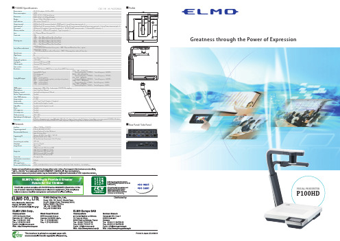
Greatness通力量表现视觉展示器P100HD说明书
Greatness through the Power of ExpressionVISUAL PRESENTERP100HD■Profile■Rear Panel/ Side PanelVivid expression enhances the understanding of the audience.The P100HD is fully integrated with an LCD Touch Panel, ensuring easy operation in every situation.In a lecture or a seminarDisplaying enlarged images of your teaching materials is the most popularapplication of the document camera.For introducing products and demonstrationsDemonstrate how to use a keyboard, asmartphone or a tablet by showing thefinger movements.In a video conferenceConduct effective meetings bydisplaying documents or real objects to participants face-to-face.For inspection or quality control in production linesDisplay enlarged images of small parts, detailed wiring or fine print on a circuit board.In an internal meetingDisplay new product samples,confidential or restricted documents.As a useful rental item for events and conferencesThe document camera is a favorite item for presenters at seminars andconferences.Built-in Touch Panel LCD monitorNetwork Server FunctionSimple Operation with Wireless Remote Control3.4 Megapixel CMOS Image Sensor & HDMIP100HD’s Touch Panel LCD monitor is intuitive and easy to use. It allows you to straighten out the position of your materials without turning around to look at the image on the screen behind you.By connecting the P100HD to a computer using a LAN cable, you can remotely control the P100HD and view or capture the live image via web browser.The uniquely designed remote control allows users to control the P100HD from almost anywhere in the room.The P100HD’s megapixel image sensor captures everything from fine print to three-dimensional objects in 1080p full HD.Powerful Optical & Digital ZoomSmooth Movement with Audio at 30fpsFlexible System ConfigurationSave Presentations on ExternalMemory16x Optical zoom x 8x Digital zoom = 128x Total zoomThe powerful Optical & Digital zoom ensure that all materials, such as detailed craftsmanship or artwork, tiny components on circuit boards, or small print in books are clearly displayed when enlarged.The P100HD can capture and reproducemovement with audio at 30fps (frames per second) for the display of truly smooth, natural-looking motion.The P100HD is equipped with a built-in switcher function. It can handle different image signals such as RGB and HDMI and control multiple devices. By using the ELMO CRA-1 Wireless Tablet, you can annotate on live images captured by the P100HD while the image is displayed on a large screen. The CRA-1’s wireless adapter can be plugged directly into the P100HD, allowing direct annotation on live images from anywhere in the room without having to use a computer.Both video files (mp4) and still images (JPEG) can be saved on a USB flash drive or SD memory card for future use.The saved image files can be displayed as individual files or as slideshow without using a computer or other hardware. The audio from the built-in microphone and the externalaudio input can be output from the audio line output and the HDMI output.Optical zoom×16Digital zoom×8CRA-1 Wireless Tablet(sold separately)Receives IR signal through Wireless AdapterP100HD 30fps(frames per second)Smooth。
Philips hdd100音乐播放器说明说明书
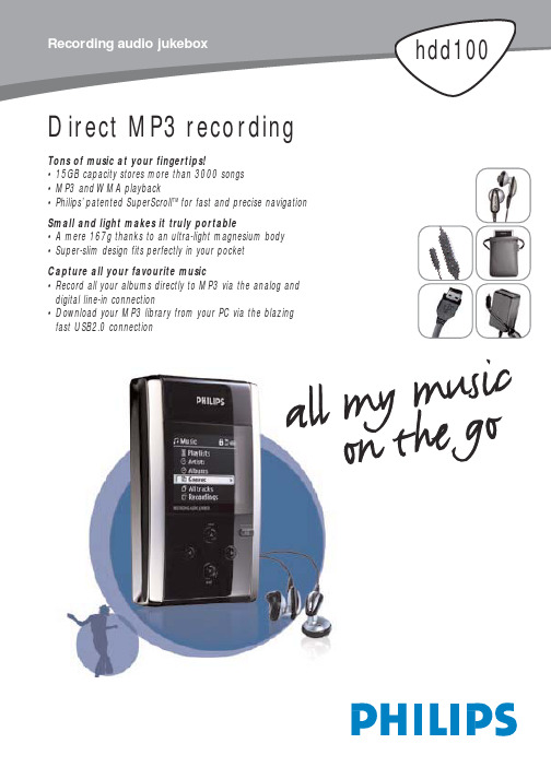
Direct MP3 recording Tons of music at your fingertips!•15GB capacity stores more than 3000 songs•MP3 and WMA playback•Philips’patented SuperScroll TM for fast and precise navigation Small and light makes it truly portable•A mere 167g thanks to an ultra-light magnesium body •Super-slim design fits perfectly in your pocketCapture all your favourite music•Record all your albums directly to MP3 via the analog anddigital line-in connection•Download your MP3 library from your PC via the blazing fast USB2.0 connectionStandard product informationFeatures•EQ by genre Automatic selection ofEQ setting dependingon genre •Programmable EQ Equalizer presets canbe reprogrammed andrenamed •SuperScroll TM2-step manuallycontrolled scroll speed •Bass enhancer DBB (Dynamic BassBoost)Playback•MP3 playback8-320 kbps and VBR •WMA playback32-192 kbps •Sample rates (kHz)8,11.025,16,22.050,32,44.1,48•ID3-tag support Y es (ver 1.2/2.0) Recording•Voice recording (MP3)Via built-in microphone(mono)•Audio recording (MP3) Via 3.5mm line-in jack(stereo)-Analog(64/128/192 kbps)-Digital optical(64/128/192 kbps) Storage•Hard disk Low profile 1.8" HDD •Capacity15GB (Actual formattedcapacity of HDD100will be less)System•Output power2x5mW (16 Ohm)•Frequency response20-20.000Hz•THD0.01%-0.1%•Equalizer5-band DSP controlled •Buffer memory32MB for approx 30min music buffer(depending on bitrate)•USB connection USB2.0 (USB1.1compatible)•Display4-level greyscale,160x128 pixels •Backlight White superbrightLED•Battery Built-in 1200mAhLi-Polymer•Lens Hardened OpticalGlass•Encasing Die-cast moldedmagnesium Connections•Stereo headphone•Wired remote control•Mini USB (B-type)•DC power supply•Combined analog and digital input General•Product dimensions106.5 L x 64.4 W(mm)x 19.9 H•Packaging dimensions252 L x 153 W(mm)x 63 H•Master carton262 L x 163 Wdimensions (mm)x 89 H•Master carton quantity1•Weight (g)167•Country of origin ChinaAccessories•5-key in-line remote control (AY3779)•Hi-quality in-ear headphones (SBC HE570/77P)•T ravel pouch (AY3274)•USB2.0 compatible cable (AY3911)•Multi voltage AC/DC power adapter/charger(AY3192/00)•CD-ROM with software and full user manual(AY3498)•Quick-Start-GuideSoftware•Media management Only via suppliedMedia ManagementSoftware•General data storage Directly accessible viaWindows Explorer(Mass Storage DeviceClass compliant)•PC system requirements OS:Windows 98SEor later•Software Internet connection(for other IFUlanguages than English,and for futurefirmware upgrades)Direct MP3 recordingRecord directly to MP3 files via built-in microphoneand digital or analog line-in connection.MP3 and WMA playbackYou can play MP3 files as well as Windows MediaAudio files.SuperScroll TM keys for faster navigationDouble action search buttons allow easy speedcontrol when scrolling through large libraries.Youcan choose to move through your playlist one songat a time or just press and hold down a little harderto SuperScroll TM swiftly to your desired track.Programmable genre-linked equalizerDepending on the genre,the player can automaticallyselect the desired equalizer setting.And with 4traditional presets:Rock,Pop,Jazz and Classic,you caneasily tag your music by genre.So the next time youplay a particular track,it will instantlyrecognize your chosen setting.Super-fast USB2.0 PC connectionSupports the new USB2.0 standard enabling thespeedy transfer of data between USB connecteddevices at 480kbps.It is also backwards compatiblewith the old USB1.1 standard,so a USB1.1 computerport will work with HDD100 using the same bypacked cable and connectors.Can be used as external hard diskConnects through USB to be used as a spare portableHDD storage via Windows Explorer.15GB of immensestorage capacity allows you to pack an entire world ofmusic and data into your HDD100.EAN:87 10895 76772 9 (/00)EAN:87 10895 77637 0 (/05)Printed in Hong Kong 2003-03-20Specifications subject to modificationwithout notice2003 © Koninklijke Philips Electronics N.V.All rights reserved。
Power 100HD 高功率汽车sound系统技术手册说明书
POWER 1OOHD AMPLIFIEROWNER’S MANUALPRACTICE SAFE SOUND™CONTINUOUS EXPOSURE TO SOUND PRESSURE LEVELS OVER 100dB MAY CAUSE PERMANENT HEARING LOSS. HIGH-POWERED AUTOSOUND SYSTEMS MAY PRODUCE SOUND PRESSURE LEVELS WELL OVER 130dB. USE COMMON SENSE AND PRACTICE SAFE SOUND.Make your system complete with installation access-ories from , a division of Rockford Corp. Ask your sales-man about Perfect Power alternators, power cables, speaker wire, connec-tors, cosmetic accessories and fabric.THANK YOU FOR CHOOSING ROCKFORD FOSGATE IN YOUR CAR AUDIO SYSTEM. WE HAND BUILD OUR PRODUCTS IN AMERICA WITH THE BEST PARTS AVAILABLE, SO WE’RE CONFIDENT YOU’LL BE ENJOYING MUSIC WITH THE PUNCH FOR MANY YEARS.WE RECOMMEND THAT YOU HAVE YOUR NEW ROCKFORD FOSGATE PRODUCT PROFESSIONALLY INSTALLED. THE LENGTH AND NATURE OF YOUR WARRANTY ARE DRAMATICALLY AFFECTED IF YOU ATTEMPT TO INSTALL IT YOURSELF.INTRODUCTIONThe Rockford Fosgate Power 100HD is an automotive stereopower amplifier which will provide state-of-the-art sound in cars,vans, boats, or wherever a 9 to 16 volt battery is available.The Power 100HD adjustable input circuits are designed tomatch almost any music source, from low preamp levels tospeaker levels, with negligible noise. The amplifiers will drive allnormal speaker types, impedances, and configurations.Internal fusing in the Power 100HD amplifier prevents damagedue to shorts, system power problems or internal failures. ThePower 100HD incorporates new internal battery line filtering andextensive noise prevention circuitry.Due to the technical nature of our products, no installationinstructions are enclosed. Damage to your new amplifier, speakersor electrical system may result from improper installation, thereforethis Power 100HD amplifier should be PROFESSIONALLYINSTALLED.LIMITED WARRANTYELECTRONICS WARRANTYRockford Fosgate warrants electronic components to the origi-nal purchaser for two years parts and one year labor providingproduct was purchased from and installed by an authorizedRockford Fosgate dealer. Proof of purchase must accom-pany returned product.SPEAKER WARRANTYRockford Fosgate warrants all loudspeakers to the originalpurchaser for a period of two years providing the product waspurchased from and installed by an authorized Rockford Fosgatedealer. Proof of purchase must accompany returned product.All warranty claims must be processed through authorizeddealers. SHOULD YOU NEED TO OBTAIN SERVICE ONELECTRONICS OR SPEAKERS, RETURN THE PRODUCTTO YOUR NEAREST ROCKFORD FOSGATE DEALER ORCALL 602-967-3565 FOR THE DEALER NEAREST YOU. Allproducts must be returned, freight prepaid, to an authorizedRockford Fosgate repair center where it will be repaired orreplaced, at our option, and returned to you prepaid.WHAT THE WARRANTY DOESNOT COVERWarranty does not cover physical abuse, the cabinet or anyappearance item, any accessory used in conjunction with theproduct, or any damage to the product resulting from alteration,accident, misuse or abuse. This warranty does not apply if theparts or labor, which would otherwise be provided withoutcharge under this warranty, are obtained from any source otherthan Rockford or an authorized service center. Parts notcovered under warranty will be repaired or replaced and re-turned C.O.D. for the parts and freight. For speaker boxes, theentire cabinet may be returned for service, but return will befreight collect. Rockford limits obligation under any implied2warranties under state laws to a period not to exceed the warranty period.WARRANTYOUTSlDETHEU.S.,PLEASECONSULTYOUR LOCAL AGENT.ROCKFORD CORPORATION613 S. ROCKFORD DRIVETEMPE, AZ 85281 U.S.A.(602) 967-35653POWER 1OOHD SPECIFICATIONSPOWER RATINGS:4 Ohms: 15 Watts per channel continuous power, 4 channelsdriven into 4 Ohms, from 20 to 20,000 Hertz, withless than 0.05% THD + N (Total Harmonic Distor-tion plus Noise).4 Ohms: 30 Watts per channel continuous power, 4 channelsdriven into 4 Ohms at 1000 Hertz, with less than10% THD + N (Total Harmonic Distortion plusNoise).2 Ohms: 25 Watts per channel continuous power, 4 channelsdriven into 2 Ohms, from 20 to 20,000 Hertz, withless than 0.1% THD + N (Total Harmonic Distortionplus Noise).POWER RATINGS: 2 CHANNEL (Bridged)50 Watts per channel continuous power driven into4 Ohms, from 20-20,000 Hertz, with less than0.10% THD+ N.(Total Harmonic Distortion plus Noise)Frequency Response: 20 to 20K Hertz, ± 5 dB.Bandwidth: 15 to l00K Hz ± 3dBDamping Factor: At circuit board:over 50 (referred to 4 Ohms)Signal to Noise Ratio: Over 80 dB, unweightedSlew Factor: Over 5IM Distortion (IHF): Less than 0.05%Input Gain: Variable from 40 dBV to 14 dBVFactory pre-set at 32 dBV(correct for millivolt-rated source units).4Rockford FosgateA Division of Rockford Corporation613 South Rockford Drive Tempe, Arizona 85281 U.S.A.602 - 967 - 3565。
MSR-100串行读卡器使用指南1.5
描述
定义
值
开始符
STX
0x20
终止符
ETX
0x03
应答
ACK
0x06
无应答
NAK
0x15
1.2.3 协议描述 通信必须先由主机发送命令和数据给 MSR MSR 执行命令完毕后 将命令执行的状态
和响应数据发回主机
开始通信前 收发双方必须处于就绪状态 首先主机发出 STX 然后等待 MSR 的响应 ACK 若在 10ms 内未检测到此响应 或收到 NAK 则再次发送 STX 如此反复 3 次 若 3 次均未收 到正确应答 ACK 则退出本次传输 将错误代码返回给主程序 由主程序进行错误处理 若
一 红灯的作用 红灯是用来指示 Config()函数的执行状态的 若该函数执行成功 则红灯亮 否则红灯 不亮 若读卡器执行了 Close() 函数 则红灯灭 二 绿灯的作用 有四种情况可能改变绿灯的状态 1 执行 Config()函数和 Close()函数 若 Config()函数执行成功 则绿灯灭 否则绿灯亮 若读卡器执行了 Close() 函数 则 绿灯灭 读卡器上电时 将自动执行 Config()函数 因此读卡器稳定后 若红灯亮 绿灯灭 则 工作正常 若红灯灭 绿灯亮 则 RC500 初始化失败 将不能对卡进行操作 必须送修 2 当读卡器上电进入正常工作状态后 此时红灯亮 绿灯灭 在 PC 机未发出任何命 令之前 若读卡器感应区内有卡 绿灯将亮 否则绿灯灭 在 PC 机已发出任何一条命令后 此功能消失 因此在未启动 PC 机程序之前 本读卡器可以指示感应区内是否有卡 3 执行 Set_Control_Bit()函数将熄灭绿灯 执行 Clr_Control_Bit()函数将点亮绿灯 4 执行 Alarm()函数将可使绿灯闪烁 三 蜂鸣器 执行 Alarm()函数可使直流蜂鸣器发声 可控制蜂鸣器发声的持续时间 间歇时间及重复 次数
磁条读写器使用说明书
磁条读写器使用说明1.型号说明:1000单二轨低磁读写器1000H单二轨高磁读写器2000一二轨低磁读写器2000H一二轨高磁读写器3000二三轨低磁读写器3000H二三轨高磁读写器2、磁卡读写器技术要求工作环境:温度:0℃-·40℃湿度:20%-90%RH电源:DC+5V±0.5V ≤300MA体积:215×70×65mm重量:≤1.4KG通讯参数:波特率9600BPS格式:8位数据位、1位停止位、无校验磁卡标准:符合ISO、IBM标准磁道:1、2、3道读写记录密度:75BPI/210BPI拉卡速度:10cm/s-180cm/s寿命:≥50万次错误率:<1/1000读写字符集兼容ISO、IBM两种标准字符集:ISO字符集IBM字符集3、电缆连接线定义磁条读写器的电源是通过通讯电缆提供的,接口为RS-232九芯母头。
通讯电缆的信号排列如下列所示:4、自检功能:磁条读写器在每次上电开机或收到复位命令后都进行自检,自检开始时红绿黄指示灯都亮,自检结束后指示灯灭。
自检完毕后,SBH-6型磁条读写器进入正常工作状态。
4.1.1磁条读写器能与目前市场上的各种类终端配套。
操作要求4.1.2 读操作:磁条读写器接到读命令后,绿色指示灯亮,此时操作员便可以进行读操作,指示灯灭表示读操作成功,如果红色指示灯亮则表示读操作失败,可再次发读命令进行读操作。
可以自动识别磁条信息ISO、IBM标准。
4.1.3 写操作:磁条读写器收到写命令和正确的写数据后,绿色指示灯闪烁,此时操作员便可以拉卡进行写操作,指示灯灭表示写操作成功,如果红色指示灯亮则表示写操作失败,可再发命令进行写操作。
4.1.4 串行命令集:以进入磁条读写器的信息为下行数据。
以磁条读写器送出的信息为上行数据。
字符集为0-9及‘,=4.2 磁条读写器读写控制磁卡可支持以下6种标准格式:起始符终止符格式1: BA ………… F格式2: B ………… C格式3: B ………… F格式4: BA …………C格式5: D ………… F格式6: D ………… C5、磁条读写器控制命令集磁条读写器开机或软复位缺省状态设置为ISO标准。
DDSO-100 HDSO-100 型使用说明书
4.8 垂直移动
当鼠标移到左边或右边的 Y 轴附近。将会显示一对上下的半透明箭头,同时鼠标变成 小手形状。此时,按钮鼠标左键,移动鼠标,曲线将随鼠标而上下移动。可以用快捷键“↓” 和“↑”来实现左边 Y 轴曲线的上下移动,和用 Shift+“↓”和 Shift+“↑”来实现右边 Y 轴 哈尔滨仪星电子科技
4.1 鼠标拖动 …………………………………………………………………… 4 鼠标拖动…………………………………………………………………… …………………………………………………………………… 4 4.2 鼠标测量 鼠标测量…………………………………………………………………… ………………………………………………………………… 5 4.3 采样点显示 采样点显示………………………………………………………………… …………………………………………………………………… 5 4.4 水平缩放 水平缩放…………………………………………………………………… …………………………………………………………………… 5 4.5 水平移动 水平移动…………………………………………………………………… 4.6 水平微调 …………………………………………………………………… 5 水平微调…………………………………………………………………… …………………………………………………………………… 5 4.7 垂直缩放 垂直缩放…………………………………………………………………… …………………………………………………………………… 5 4.8 垂直移动 垂直移动…………………………………………………………………… …………………………………………………………………… 5 4.9 区域放大 区域放大……………………………………………………………………
标签打印机 HD100 HD130 用户手册说明书
标签打印机HD100HD130用户手册厦门汉印电子技术有限公司地址:厦门火炬高新区创业园昂业楼305A室网址:更改记录版本日期更改内容更改审核承认1.02016.7.15初版尤翠虹杨开趣余赞芳1.12016.10.91.灯号定义更新2.增加标签侦测器使用部分3.增加海鸥驱动使用部分4.增加标签编辑软件使用部分5.渠道工具更新6.海鸥驱动更新7.HD100和HD130共用说明书尤翠虹杨开趣余赞芳目录手册信息 (1)安全须知 (2)第1章产品简介 (5)1.1开箱清单 (5)1.2外观及组件 (6)1.3产品尺寸 (7)第2章产品规格 (8)第3章安装和使用 (10)3.1介质安装 (10)3.2电源连接 (14)3.3接口连接 (15)3.4标签侦测器 (17)3.5操作面板 (25)3.6基本功能使用 (27)第4章接口 (30)4.1USB接口 (30)4.2其他可选接口 (30)第5章清洁打印机 (32)5.1清洁打印头 (32)5.2清洁传感器、胶辊和纸张路径 (32)第6章标签打印机工具使用说明 (33)6.1工具准备 (33)6.2工具的使用 (33)第7章海鸥Windows驱动说明 (47)7.1驱动介绍 (47)7.2程序准备 (47)7.3驱动安装 (48)7.4驱动使用 (53)7.5纸张大小 (70)第8章BarTender Ultralite标签编辑软件说明 (71)8.1软件介绍 (71)8.2软件准备 (71)8.3软件安装 (72)8.4软件使用 (78)⏹声明本手册内容未经同意不得随意更改,我司保留在技术、零部件、软件和硬件上变更产品的权利。
用户如果需要与产品有关的进一步信息,可与我司联系。
未经公司的书面许可,本手册的任何章节不得以任何形式、通过任何手段进行复制或传送。
⏹版权本手册于2016年印制,版权属于厦门汉印电子技术有限公司。
中国印制。
1.1版本。
⏹安全警告警告:打印头为发热部件,打印过程中和打印刚结束,不要触摸打印头以及周边部件。
HD显示控制仪表说明书
仪表失控时,请检查输出控制连线是否正确,外部负载有 否短路 \ 断路 \ 错线等导致仪表内部元件损坏,必要时可 打开仪表检查,输出端子铜箔 \ 输入输出保护电阻有否 损坏等.
HD8A 传感器检测控制仪表
使用手册
非常感谢您选择使用本公司的产品! 为了您的安全,在使用之前请仔细阅读本手册,若对本产品 有任何疑问,请与我们的销售员或您购买此仪表的经销商联 系。本手册如有改动恕不另行通知。
安全注意
为防触电或控制器失效,所有接线工作完成后方可供电,禁止带电 接线,为正确接线,不使用的端子,请勿接线。 清洁控制器前必须断开电后方可操作。 为防止控制器损坏或失效,请用仪表规定的电压供电,以免损坏本产 品或引起火灾。 为防止控制器失效或报废,严禁改动仪表。 输出继电器的使用寿命因开关容量和开关条件不同而存在很大差距, 因此必须考虑实际使用条件,请在额定负载和电气使用寿命内使用输 出继电器,如果输出继电器超过其使用寿命,触点可能会熔化或烧断, 有时会引起火灾。
96W × 48H × 80L
输入信号类型
可测量范围
mA V(AV/DV)
mV
Rt
0~1mA.0~10mA.4~20mA 0~5V.0~10V. 0~500V
0~10mV.±100mV 0~400Ω 0~10K Cu50 Cu100 -50~150℃
Pt
-200~650℃
Pr
20 段折线化输入处理
输入阻抗 ≤ 150Ω ≤ 200KΩ ≤ 2MΩ
参数设定
1 、报警参数设定:显示方式下,按 S E T 大于 3 秒可进入报警方式设定
HD收费机系列产品用户手册
注意细则1.使用HD收费机系列产品之前请仔细查看本手册。
2.禁止用户使用“初始化操作”中的【下载程序】功能。
3.如果有必要请与厂家或销售商联系取得技术支持或到厂家参加技术培训。
4.本手册介绍的系统设置软件只作为产品的功能设置和测试使用,不可作为商业用途,否则造成的不良后果(如数据丢失、密码丢失、不能通讯等)由用户自行负责。
5.用户如果需要方便地使用产品的某些功能,请进行第二次开发。
6.本产品如有功能变动,将以厂家通知为准。
7.系统安装必须参照第二章第四节网络安装介绍,否则将会影响系统的稳定性单机快速测试a.用随机附带的KS232通讯线将机具与计算机串口正确连接;b.运行T设置软件;c.配置端口、波特率;d.校时成功;e.单机寻机成功;f.对读写器进行密码初始化操作;g.按需求完成各项属性设置(此步骤可省略);h.按需求完成各种功能设置(此步骤可省略);i.用发卡器进行发卡操作,收费机不带发卡功能;j.读写器可以开始进行正常的工作,可以刷卡;k.取数据。
第一章产品简介感应式IC卡HD系列读写器主要功能就是收集保存并处理刷卡数据,并在与电脑连接后可将数据传送给电脑作进一步处理。
该系列读写器最大的特点就是硬件性能稳定,软件接口函数丰富,功能强大,用户可自行对机具的许多特殊功能进行设置,密码用户管理,安全灵活,数据采用DES算法,保密性强。
HD系列读写器根据需要进行组合,可应用于收费、门禁(人员出入控制)、收费、会议签到、车辆管制、身份识别以及巡更等系统,也可以应用于一卡通工程。
第一节产品类型介绍HD系列IC卡读写器类型按用途可分为三类:收费机、门禁机、收费机。
每一类按读卡类型又可分为多个机种。
具体命名规则如下:HD X P —K/M表示机具类型K/M ---- 收费机K/M2 ---- 收费机2型S ---- 卧式收费机S2 --- 立式收费机表示读卡类型P ---- PHILIPS公司ML、M1系列T ---- Atmel公司Temic卡E ---- EM 公司ID卡表示公司第X代产品,如2、3、4系列产品注:收费系列机型只能读写Mifare 1卡。
IC卡读写器说明书
HCE-200系列全功能IC卡读写机使用说明一、用途:HCE200系列全功能IC卡读写机是开发IC卡相关产品及系统集成必备的前端处理设备,其丰富、完善的接口函数,可方便地应用于工商、电信、邮政、税务、银行、保险、医疗及各种收费、储值、查询等智能卡管理应用系统中。
二、主要功能:1、提供串口通讯方式2、串口波特率采用9600BPS3、提供多种卡座方式4、提供了丰富的二次开发平台和范例三、技术指标:1、HCE201-W(自带电源)电源AC 220V ±10%传输波特率 9600bp功耗<0.3W温湿度0℃~40℃ 10%~90%读写速度<0.2秒/次通讯接口: RS232串口串口的波特率: 9600 BPS2、HCE-201(键盘口取电)电源:键盘口供电最大功耗: 100 mW环境温度:0°~ 50 °C相对湿度: 30% ~ 95%外型尺寸:150mm′108mm′100mm卡座寿命:10万次电磁辐射干扰CE89/336四、可读写的卡型:1、存贮器(Memory)卡ATMEL公司的AT24C01A、24C02、24C04、24C08、24C16、AT24C64,AT88SC101/2,AT88SC1601/1604,AT45D041卡2、IEMENS公司的SLE4432/4442,SLE4418/4428,SLE4404,SLE4406卡,国内外芯片厂商研制的以上产品的兼容产品3、写T=0/1协议的CPU卡。
4、支持符合ISO7816-3,4标准和EMV标准及符合中国人民银行标准的PBOCCPU卡(T=0、T=1)、SAM卡;五、配套软件:HCE200全功能IC卡读写机的软件包括三部分:演示软件、库函数和应用范例a. 演示软件IC卡读写器功能演示软件WINDOWS版DEMO.EXE,您可以用该软件来测试您的读写器有没有连接正确或测试您的卡的卡类型或进行一些卡功能测试。
注意:在开发过程中请检查自己的读写卡过程有没有正确,用该演示程序来验证是一个好办法!b. 库函数1、C语言接口函数库(Borland C、Microsofe C)2、FOXPRO FOR DOS(2.6) 接口函数库3、WINDOWS 16位动态库4、WINDOWS 32位动态库5、UNIX函数库(SCO UNIX5.0)请根据您的开发环境来选用正确的库函数。
- 1、下载文档前请自行甄别文档内容的完整性,平台不提供额外的编辑、内容补充、找答案等附加服务。
- 2、"仅部分预览"的文档,不可在线预览部分如存在完整性等问题,可反馈申请退款(可完整预览的文档不适用该条件!)。
- 3、如文档侵犯您的权益,请联系客服反馈,我们会尽快为您处理(人工客服工作时间:9:00-18:30)。
HD100智能卡读写器说明书广东华大集成技术有限责任公司
HD100智能卡读写器
1.0 产品简介
智能卡读写器技术能够满足日益增长的网络办
公的要求(比如远程办公、家庭办公)以及降低个人
网络被非法侵用的风险。
我们基于智能卡应用的解决
方案能够使得用户安全使用电脑、桌面设备、内联网
和企业外部网络。
HD-100智能卡读写器能为您的应用方案锦上添花。
当今,智能卡正成为网络安全和电子支付系统的一个必不可少的组成部分,HD-100读写器拥有数据加密功能从而能够提供安全的网络计算环境。
不仅如此,它还有内置的SAM卡槽,卡片验证可以在它内部完成。
此外,它的安全存取模块能够保护密钥不被盗取,这就使得应用方案能更加安全地进行。
HD-100智能卡读写器能够支持安全存取模块,使用它能大大提高您的系统的安全性。
这款USB全速设备专为PC环境而设计,是连接智能卡和电脑之间通信的桥梁。
2.0产品特性
▪支持接触式CPU卡、SLE 4428/42
▪具有两个SAM插槽,确保应用安全。
在通电的时候可以检测到SAM的状态。
但电流稳定时,读写器不会检测SAM的状态。
▪支持ISO-7816 A, B, C (5V, 3V, 1.8V)等级的卡
▪能读写所有符合T=0 或T=1协议的微处理卡
▪支持PPS(协议和参数选择),读写速度为1,743 – 250,000 bps
▪USB全速计算机接口
▪短路保护
3.0典型应用
▪控制网络访问
▪软件锁定
▪数字签名
▪客户积分优惠和促销活动
▪储值
▪身份认证
▪电子票务
▪停车收费
▪自动收费系统
▪客户积分优惠
▪考勤
4.0、如何操作卡片
首先,将我司HD100读写器数据线接在电脑USB后,即可使用读写器操作卡片,无需安装驱动。
如何操作非接触卡片:
本款产品为接触式读写器,不支持读非接卡片。
如何操作大卡:
首先将接触卡,芯片朝上,推入卡座里,如果您推入是正确的话,,然后就可以用我司提供的操作程序对卡片进行操作了。
如何操作PSAM
先将读写器底面朝上,看见有PSAM字样的地方,顺着箭头的方向,将滑盖推开,可以看见里面有个小卡座,依据上面写的LOCK和OPEN字样写的方向将卡座打开放入卡片扣上后即可。
然后就可以用我司提供的操作程序对卡片进行操作了。
