英文文献 科技类 原文及翻译 (电子 电气 自动化 通信…)10
电气专业英文文献翻译

一个非线性电谐振器作为一个简单的触摸感应开关与记忆存储器摘要我们介绍了一个新的切换机构,它依赖于一个简单的非线性电谐振器,其中包括一个变容二极管作为其电容元件的双稳态的切换动作,开关动作可以快速和自包含在电路中。
不同于一个触发器的翻转,其状态是通过施加一个TTL脉冲翻转,这种非线性开关可以通过磁,电感性或电容性耦合被接合到外部电路,在这种方式中,开关变为本质触摸敏感。
另外,开关动作也可以使用频移键控(FSK)调制,实现有记忆状态的快速操作的承诺。
我们通过构建一个触摸感应的LED 点阵证明这些想法的潜在应用。
关键词:非线性开关;电气谐振器的双稳态特性;触摸灵敏度1.介绍在数字电子技术,可以在两个状态之间进行切换的典型的存储元件,当然是触发器。
SR触发器无处不在,例如,它包含两个交叉的NOR(或NAND)门。
当无信号时,触发器的状态保持在其以前的配置,并以它翻转到另一种状态的简要电压信号(TTL脉冲)被施加到相应的输入。
在这里,我们提出了一个非线性电谐振器,在某些方面的作用就像一个触发器。
正如我们表明,它的两个状态之间的切换是通过驱动频率协议(FSK调制)来实现,或通过将一个磁铁或到附近的谐振器的电感器来完成的,它也可以通过电容耦合被切换。
设置完成后,系统会记住它的状态,直到另一个开关动作。
然而,不像一般的触发器,该元件可被诱导以从电路的外面进行切换。
另外,频率调制方案可以快速切换。
最后,我们将通过构建一个可控的LED阵列展示这一理念的应用程序。
由于开关动作可以出现在响应触摸(通过改变电容)或靠近磁铁或电感器,这种谐振就像触摸感应开关,这也许会让人联想到一个“触摸灯”。
当这种灯的金属外壳被触摸时,它的有效电容增加。
有那么多的方式来电容转换为数字输出[1]。
即使是最简单的方案采用了数字集成电路元件:一个固定幅度的交流电压驱动器充电和放电的住房,并在接触充电电流增加,进一步电路检测这种增强的电流和开关一个触发器。
电气工程及其自动化专业_外文文献_英文文献_外文翻译_plc方面.
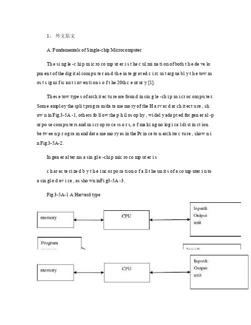
1、外文原文A: Fundamentals of Single-chip MicrocomputerTh e si ng le -c hi p m ic ro co mp ut er i s t he c ul mi na ti on of both t h e de ve lo pm en t of the dig it al com pu te r an d th e in te gr at ed c i rc ui t arg ua bl y t h e tow m os t s ig ni f ic an t i nv en ti on s o f t he 20th c e nt ur y [1].Th es e tow type s of arch it ec tu re are foun d in sin g le -ch i p m i cr oc om pu te r. Som e empl oy the spli t prog ra m/da ta me mo ry of the H a rv ar d ar ch it ect u re , sh ow n in Fig.3-5A -1, oth ers fo ll ow the p h il os op hy , wi del y ada pt ed for gen er al -p ur po se com pu te rs and m i cr op ro ce ss o r s, o f ma ki ng no log i ca l di st in ct ion be tw ee n p r og ra m and dat a me mo ry as in the Pr in ce to n arch ite c tu re , show n i n Fig.3-5A-2.In gen er al ter ms a sin gl e -chi p mic ro co mp ut er i sc h ar ac te ri zed b y t he i nc or po ra ti on of a ll t he un it s of a co mp uter i n to a sin gl e d ev i ce , as sho wn inFi g3-5A -3.Fig.3-5A-1 A Harvard typeFig.3-5A-2. A conventional Princeton computerFig3-5A-3. Principal features of a microcomputerRead only memory (ROM.R OM is usua ll y for the pe rm an ent,n o n-vo la ti le stor a ge of an app lic a ti on s pr og ra m .M an ym i cr oc om pu te rs and m are inte nd e d for high -v ol um e ap pl ic at ions a n d he nc e t h e eco n om ic al man uf act u re of th e de vic e s re qu ir es t h at t he cont en t s o f t he prog ra m me m or y be co mm it t ed perm a ne ntly d u ri ng the man ufa c tu re of ch ip s .Cl ea rl y, thi s im pl ie s a r i go ro us app ro ach to ROM cod e deve l op me nt sin ce cha ng es can not b e mad e afte r manu f a c tu re .Th is dev e lo pm en t proc ess may invo lv e e m ul at io n us in g aso ph is ti ca te d de ve lo pm en t sy ste m wit h a h a rd wa re emu la tio n cap ab il it y as w el l as the use o f po we rf ul s o ft wa re too ls.So me man uf act u re rs pro vi de add it io na l RO M opt i on s by i n cl ud in g in their ra n ge dev ic es wit h (or int en de d fo r use wit h u s er pro gr am ma ble me mo ry. Th e sim p le st of th es e is usu al ly d e vi ce whi ch can op er at e in a micro p ro ce ssor mod e by usi ng som e o f the inp ut /outp u t li ne s as an ad dr es s an d da ta b us fora c ce ss in g ex te rna l mem or y. Thi s t y pe of de vi ce can beh av ef u nc ti on al ly as th e sing le chip mi cr oc om pu te r from whi ch it is d e ri ve d al be it wit h re st ri ct ed I/O and a mod if ied ex te rn al c i rc ui t. The use of thes e d ev ic es is com mo n eve n in prod uc ti on c i rc ui ts wher e t he vo lu me does no tj us ti f y t h e d ev el o pm en t c osts o f c us to m o n -ch i p R OM [2];t he re c a n s ti ll bea s ignif i ca nt saving i n I /O and o th er c h ip s com pa re d to a conv en ti on al mi c ro pr oc es sor b a se d ci rc ui t. Mor e ex ac t re pl ace m en t fo r RO M dev i ce s ca n be o b ta in ed in th e fo rm of va ri an ts w it h 'p ig gy -b ack 'E P RO M(Er as ab le pro gr am ma bl e ROM s oc ke ts or dev ic e s with EPROM i n st ea d o f RO M 。
英文文献科技类原文及翻译(电子电气自动化通信…)50

目录1译文 (1)2原文 (7)1参考文献译文绿色创想建筑商计划提供了节能解决方案与行业认可的新住房平均相比,绿色畅想建筑商计划旨在降低家用能源和水的想好,减少排放。
该项目创新性地结合了建筑科学和高品质的产品,在帮助建筑商和开发商建造舒适型住房的同时,降低房屋对环境的影响。
随着生活费用的不断上涨,悦来愈多的人开始考虑将环保技术纳入新住房当中。
与行业认可的新住房陪你冠军水瓶相比,依照GE绿色创想建筑商计划所建造的房屋每年客减少20%的能耗与室内用水量,并且使生活用气排放量减少20%。
对于一套面积为2500平方英尺的住房而言,该计划每年可使购房者减少600至1500美元的电费和水费。
自该计划于2007年5月启动以来,整个美国与加拿大的建筑商与开发商纷纷申请建造绿色创想式房屋,其中包括德州西斯顿峡谷们的社区开发商。
按照绿色畅想计划正在开发的首个峡谷么社区被称为Discovery Companies,预计将于2008年夏季开盘。
加拿大的Fi的零售税环保想象住房计划推出在2007年9月,GE加拿大与波尔多发展组织签订计划,决定在位于加拿大阿尔伯他省卡尔加里西部的社区Rocky View实施加拿大首个绿色创想建筑商计划。
这块地区60多年来,一直有当地的一个牧民家庭所有,长期以来除了放养家畜之外始终难以用于其他用途。
迫于地区发展的强大压力,这个家庭决定对这块土地进行开发。
当这家人了解到如何最邮箱的进行地产开发之后,开始认真考虑如何处理这篇土地。
其中,家庭价值、对环境的保护意识以及社区精神都称为了需要考虑的关键问题。
实施证明,将GE的绿色创想建筑商计划与波尔多发展组织的环境可持续发展战略相结合是非常成功的。
规划中的面积为1750英亩的混用型绿色创想建筑商和谐开发项目见那个进行客持续开发,其中包括关于有效实用土地的创新性环保计划。
竣工使,此开放项目将建筑起3500所住房和衣架保健中心、一个27洞国际高尔夫球场、一所学校和一篇商业用地。
电气毕业论文设计英语文献原文+翻译.doc

标准文档外文翻译院(系)专业班级姓名学号指导教师年月日Programmable designed for electro-pneumatic systemscontrollerJohn F.WakerlyThis project deals with the study of electro-pneumatic systems and the programmable controller that provides an effective and easy way to control the sequence of the pneumatic actuators movement and the states of pneumatic system. The project of a specific controller for pneumatic applications join the study of automation design and the control processing of pneumatic systems with the electronic design based on microcontrollers to implement the resources of the controller.1. IntroductionThe automation systems that use electro-pneumatic technology are formed mainly by three kinds of elements: actuators or motors, sensors or buttons and control elements like valves. Nowadays, most of the control elements used to execute the logic of the system were substituted by the Programmable Logic Controller (PLC). Sensors and switches are plugged as inputs and the direct control valves for the actuators are plugged as outputs. An internal program executes all the logic necessary to the sequence of the movements, simulates other components like counter, timer and control the status of the system.With the use of the PLC, the project wins agility, because it is possible to create and simulate the system as many times as needed. Therefore, time can be saved, risk of mistakes reduced and complexity can be increased using the same elements.A conventional PLC, that is possible to find on the market from many companies, offers many resources to control not only pneumatic systems, but all kinds of system that uses electrical components. The PLC can be very versatile and robust to be applied in many kinds of application in the industry or even security system and automation of buildings.Because of those characteristics, in some applications the PLC offers to much resources that are not even used to control the system, electro-pneumatic system is one of this kind of application. The use of PLC, especially for small size systems, can be very expensive for the automation project.An alternative in this case is to create a specific controller that can offer the exactly size and resources that the project needs [3, 4]. This can be made using microcontrollers as the base of this controller.The controller, based on microcontroller, can be very specific and adapted to only one kind of machine or it can work as a generic controller that can be programmed as a usual PLC and work with logic that can be changed. All these characteristics depend on what is needed and how much experience the designer has with developing an electronic circuit and firmware for microcontroller. But the main advantage of design the controller with the microcontroller is that the designer has the total knowledge of his controller, which makes it possible to control the size of the controller, change the complexity and the application of it. It means that the project gets more independence from other companies, but at the same time the responsibility of the control of the system stays at the designer hands2. Electro-pneumatic systemOn automation system one can find three basic components mentioned before, plus a logic circuit that controls the system. An adequate technique is needed to project the logic circuit and integrate all the necessary components to execute the sequence of movements properly.For a simple direct sequence of movement an intuitive method can be used [1, 5], but for indirect or more complex sequences the intuition can generate a very complicated circuit and signal mistakes. It is necessary to use another method that can save time of the project, makea clean circuit, can eliminate occasional signal overlapping and redundant circuits. The presented method is called step-by-step or algorithmic [1, 5], it is valid for pneumatic and electro-pneumatic systems and it was used as a base in this work.The method consists of designing the systems based on standard circuits made for each change on the state of the actuators, these changes are called steps.The first part is to design those kinds of standard circuits for each step, the next task is to link the standard circuits and the last part is to connect the control elements that receive signals from sensors, switches and the previous movements, and give the air or electricity to the supply lines of each step. In Figs. 1 and 2 the standard circuits are drawn for pneumatic and electro-pneumatic system [8]. It is possible to see the relations with the previous and the next steps.3. The method applied inside the controllerThe result of the method presented before is a sequence of movements of the actuator that is well defined by steps. It means that each change on the position of the actuators is a new state of the system and the transition between states is called step.The standard circuit described before helps the designer to define the states of the systems and to define the condition to each change betweenthe states. In the end of the design, the system is defined by a sequencethat never chances and states that have the inputs and the outputs well defined. The inputs are the condition for the transition and the outputs are the result of the transition.All the configuration of those steps stays inside of the microcontroller and is executed the same way it was designed. The sequences of strings are programmed inside the controller with 5 bytes; each string has the configuration of one step of the process. There are two bytes for the inputs, one byte for the outputs and two more for the other configurations and auxiliary functions of the step. After programming, this sequence of strings is saved inside of a non-volatile memory of the microcontroller, so they can be read and executed.The controller task is not to work in the same way as a conventional PLC, but the purpose of it is to be an example of a versatile controller that is design for an specific area. A conventional PLC process the control of the system using a cycle where it makes an image of the inputs, execute all the conditions defined by the configuration programmed inside, and then update the state of the outputs. This controller works in a different way, where it read the configuration of the step, wait the condition of inputs to be satisfied, then update the state or the outputs and after that jump to the next step and start the process again.It can generate some limitations, as the fact that this controller cannot execute, inside the program, movements that must be repeated for some time, but this problem can be solved with some external logic components. Another limitation is that the controller cannot be applied on systems that have no sequence. These limitations are a characteristic of the system that must be analyzed for each application.4. Characteristics of the controllerThe controller is based on the MICROCHIP microcontroller PIC16F877 [6,7] with 40 pins, and it has all the resources needed for thisproject .It has enough pins for all the components, serial communication implemented in circuit, EEPROM memory to save all the configuration of the system and the sequence of steps. For the execution of the main program, it offers complete resources as timers and interruptions.The list of resources of the controller was created to explore all the capacity of the microcontroller to make it as complete as possible. During the step, the program chooses how to use the resources reading the configuration string of the step. This string has two bytes for digital inputs, one used as a mask and the other one used as a value expected. One byte is used to configure the outputs value. One bytes more is used for the internal timer , the analog input or time-out. The EEPROM memory inside is 256 bytes length that is enough to save the string of the steps, with this characteristic it is possible to save between 48 steps (Table 1).The controller (Fig.3) has also a display and some buttons that are used with an interactive menu to program the sequence of steps and other configurations.4.1. Interaction componentsFor the real application the controller must have some elements to interact with the final user and to offer a complete monitoring of the system resources that are available to the designer while creating the logic control of the pneumatic system (Fig.3):•Interactive mode of work; function available on the main program for didactic purposes, the user gives the signal to execute the step. •LCD display, which shows the status of the system, values of inputs, outputs, timer and statistics of the sequence execution.•Beep to give important alerts, stop, start and emergency.• Leds to show power on and others to show the state of inputs and outputs.4.2. SecurityTo make the final application works property, a correct configuration to execute the steps in the right way is needed, but more then that itmust offer solutions in case of bad functioning or problems in the execution of the sequence. The controller offers the possibility to configure two internal virtual circuits that work in parallel to the principal. These two circuits can be used as emergency or reset buttons and can return the system to a certain state at any time [2]. There are two inputs that work with interruption to get an immediate access to these functions. It is possible to configure the position, the buttons and the value of time-out of the system.4.3. User interfaceThe sequence of strings can be programmed using the interface elements of the controller. A Computer interface can also be used to generate the user program easily. With a good documentation the final user can use the interface to configure the strings of bytes that define the steps of the sequence. But it is possible to create a program with visual resources that works as a translator to the user, it changes his work to the values that the controller understands.To implement the communication between the computer interface and the controller a simple protocol with check sum and number of bytes is the minimum requirements to guarantee the integrity of the data.4.4. FirmwareThe main loop works by reading the strings of the steps from the EEPROM memory that has all the information about the steps.In each step, the status of the system is saved on the memory and it is shown on the display too. Depending of the user configuration, it can use the interruption to work with the emergency circuit or time-out to keep the system safety. In Fig.4,a block diagram of micro controller main program is presented.5. Example of electro-pneumatic systemThe system is not a representation of a specific machine, but it is made with some common movements and components found in a real one. The system is composed of four actuators. The actuators A, B and C are double acting and D-single acting. Actuator A advances and stays in specified position till the end of the cycle, it could work fixing an object to the next action for example (Fig. 5) , it is the first step. When A reaches the end position, actuator C starts his work together with B, making as many cycles as possible during the advancing of B. It depends on how fastactuator B is advancing; the speed is regulated by a flowing control valve. It was the second step. B and C are examples of actuators working together, while B pushes an object slowly, C repeats its work for some time.When B reaches the final position, C stops immediately its cycle and comes back to the initial position. The actuator D is a single acting one with spring return and works together with the back of C, it is the third step. D works making very fast forward and backward movement, just one time. Its backward movement is the fourth step. D could be a tool to make a hole on the object.When D reaches the initial position, A and B return too, it is the fifth step.Fig. 6 shows the first part of the designing process where all the movements of each step should be defined [2]. (A+) means that the actuator A moves to the advanced position and (A−) to the initial position. The movements that happen at the same time are joined together in the same step. The system has five steps.These two representations of the system (Figs. 5 and 6) together are enough to describe correctly all the sequence. With them is possible to design the whole control circuit with the necessary logic components. But till this time, it is not a complete system, because it is missing some auxiliary elements that are not included in this draws because they work in parallel with the main sequence.These auxiliary elements give more function to the circuit and are very important to the final application; the most important of them is the parallel circuit linked with all the others steps. That circuit should be able to stop the sequence at any time and change the state of the actuators to a specific position. This kind of circuit can be used as a reset or emergency buttons.The next Figs. 7 and 8 show the result of using the method without the controller. These pictures are the electric diagram of the control circuit of the example, including sensors, buttons and the coils of the electrical valves.The auxiliary elements are included, like the automatic/manual switcher that permit a continuous work and the two start buttons that make the operator of a machine use their two hands to start the process, reducing the risk of accidents.6. Changing the example to a user programIn the previous chapter, the electro-pneumatic circuits were presented, used to begin the study of the requires to control a system that work with steps and must offer all the functional elements to be used in a real application. But, as explained above, using a PLC or this specific controller, the control becomes easier and the complexity can be increasealso.Table 2 shows a resume of the elements that are necessary to control the presented example.With the time diagram, the step sequence and the elements of the system described in Table 2 and Figs. 5 and 6 it is possible to create the configuration of the steps that can be sent to the controller (Tables 3 and 4).While using a conventional PLC, the user should pay attention to the logic of the circuit when drawing the electric diagram on the interface (Figs. 7 and 8), using the programmable controller, described in this work, the user must know only the concept o f the method and program only the configuration of each step.It means that, with a conventional PLC, the user must draw the relationbetween the lines and the draw makes it hard to differentiate the steps of the sequence. Normally, one needs to execute a simulation on the interface to find mistakes on the logicThe new programming allows that the configuration of the steps be separated, like described by the method. The sequence is defined by itself and the steps are described only by the inputs and outputs for each step.The structure of the configuration follows the order:1-byte: features of the step;2-byte: mask for the inputs;3-byte: value expected on the inputs;4-byte: value for the outputs;5-byte: value for the extra function.Table 5 shows how the user program is saved inside the controller, this is the program that describes the control of the example shown before.The sequence can be defined by 25 bytes. These bytes can be dividedin five strings with 5 bytes each that define each step of the sequence (Figs. 9 and 10).7. ConclusionThe controller developed for this work (Fig. 11) shows that it is possible to create a very useful programmable controller based on microcontroller. External memories or external timers were not used in case to explore the resources that the microcontroller offers inside. Outside the microcontroller, there are only components to implement the outputs, inputs, analog input, display for the interface and the serial communication.Using only the internal memory, it is possible to control a pneumatic system that has a sequence with 48 steps if all the resources for all steps are used, but it is possible to reach sixty steps in the case of a simpler system.The programming of the controller does not use PLC languages, but a configuration that is simple and intuitive. With electro-pneumatic system, the programming follows the same technique that was used before to design the system, but here the designer work s directly with the states or steps of the system.With a very simple machine language the designer can define all the configuration of the step using four or five bytes. It depends only on his experience to use all the resources of the controller.The controller task is not to work in the same way as a commercial PLC but the purpose of it is to be an example of a versatile controller that is designed for a specific area. Because of that, it is not possible to say which one works better; the system made with microcontroller is an alternative that works in a simple way.应用于电气系统的可编程序控制器约翰 F.维克里此项目主要是研究电气系统以及简单有效的控制气流发动机的程序和气流系统的状态。
电气工程及其自动化专业 外文文献 英文文献 外文翻译 plc方面

1、外文原文(复印件)A: Fundamentals of Single-chip MicrocomputerTh e si ng le-ch i p mi cr oc om pu ter is t he c ul mi nat i on o f bo th t h e d ev el op me nt o f th e d ig it al com p ut er an d t he int e gr at ed ci rc ui ta r gu ab ly th e t ow m os t s i gn if ic ant i nv en ti on s o f t h e 20t h c en tu ry[1].Th es e to w typ e s of a rc hi te ctu r e ar e fo un d i n s in gl e-ch ip m i cr oc om pu te r. So m e em pl oy t he sp l it p ro gr am/d ata me mo ry o f th e H a rv ar d ar ch it ect u re, sh ow n i n -5A, ot he rs fo ll ow th e ph i lo so ph y, w i de ly a da pt ed fo r g en er al-p ur pos e c om pu te rs an d m i cr op ro ce ss or s, o f m a ki ng no lo gi c al di st in ct io n b e tw ee n p ro gr am a n d da t a m em ory a s i n th e Pr in cet o n ar ch it ec tu re,sh ow n in-5A.In g en er al te r ms a s in gl e-chi p m ic ro co mp ut er i sc h ar ac te ri zed b y the i nc or po ra tio n of al l t he uni t s o f a co mp ut er i n to a s in gl e dev i ce, as s ho wn in Fi g3-5A-3.-5A-1 A Harvard type-5A. A conventional Princeton computerFig3-5A-3. Principal features of a microcomputerRead only memory (ROM).R OM i s u su al ly f or th e p er ma ne nt, n o n-vo la ti le s tor a ge o f an a pp lic a ti on s pr og ra m .M an ym i cr oc om pu te rs an d mi cr oc on tr ol le r s a re in t en de d fo r h ig h-v ol ume a p pl ic at io ns a nd h en ce t he e co nom i ca l ma nu fa ct ure of t he d ev ic es r e qu ir es t ha t the co nt en ts o f the pr og ra m me mo ry b e co mm it te dp e rm an en tl y d ur in g th e m an uf ac tu re o f c hi ps . Cl ear l y, th is im pl ie sa ri g or ou s a pp roa c h t o R OM co de d e ve lo pm en t s in ce c ha ng es ca nn otb e m ad e af te r man u fa ct ur e .T hi s d e ve lo pm en t pr oce s s ma y in vo lv e e m ul at io n us in g a s op hi st ic at ed deve lo pm en t sy st em w i th a ha rd wa re e m ul at io n ca pa bil i ty a s we ll a s th e u se of po we rf ul so ft wa re t oo ls.So me m an uf act u re rs p ro vi de ad d it io na l RO M opt i on s byi n cl ud in g i n th ei r ra ng e de vi ce s wi th (or i nt en de d fo r us e wi th) u s er pr og ra mm ab le m em or y. Th e s im p le st of th es e i s us ua ll y d ev ice w h ic h ca n op er ate in a m ic ro pr oce s so r mo de b y usi n g so me o f th e i n pu t/ou tp ut li ne s as a n ad dr es s an d da ta b us f or acc e ss in g e xt er na l m e mo ry. T hi s t ype o f d ev ic e c an b e ha ve fu nc ti on al l y a s t he si ng le c h ip mi cr oc om pu te r fr om wh ic h i t i s de ri ve d a lb eit w it h r es tr ic ted I/O an d a mo di fie d e xt er na l ci rcu i t. T he u se o f t h es e RO Ml es sd e vi ce s is c om mo n e ve n in p ro du ct io n c ir cu it s wh er e t he v ol um e do es n o t ju st if y th e d e ve lo pm en t co sts of c us to m on-ch i p RO M[2];t he re c a n st il l b e a si g ni fi ca nt s a vi ng in I/O a nd ot he r c hi ps co mp ar ed t o a c on ve nt io nal mi cr op ro ce ss or b as ed c ir cu it. M o re e xa ctr e pl ac em en t fo r RO M d ev ic es c an b e o bt ai ne d in t he f o rm o f va ri an ts w i th 'pi gg y-ba ck'EP RO M(Er as ab le p ro gr am ma bl e ROM)s oc ke ts o rd e vi ce s w it h EP ROM i ns te ad o f R OM 。
电子类文献中英文翻译

外文翻译原文:Progress in ComputersThe first stored program computers began to work around 1950. The one we built in Cambridge, the EDSAC was first used in the summer of 1949.These early experimental computers were built by people like myself with varying backgrounds. We all had extensive experience in electronic engineering and were confident that that experience would stand us in good stead. This proved true, although we had some new things to learn. The most important of these was that transients must be treated correctly; what would cause a harmless flash on the screen of a television set could lead to a serious error in a computer.As far as computing circuits were concerned, we found ourselves with an embarass de richess. For example, we could use vacuum tube diodes for gates as we did in the EDSAC or pentodes with control signals on both grids, a system widely used elsewhere. This sort of choice persisted and the term families of logic came into use. Those who have worked in the computer field will remember TTL, ECL and CMOS. Of these, CMOS has now become dominant.In those early years, the IEE was still dominated by power engineering and we had to fight a number of major battles in order to get radio engineering along with the rapidly developing subject of electronics.dubbed in the IEE light current electrical engineering.properly recognised as an activity in its own right. I remember that we had some difficulty in organising a conference because the power engineers’ ways of doing things were not our ways. A minor source of irritation was that all IEE published papers were expected to start with a lengthy statement of earlier practice, something difficult to do when there was no earlier practice Consolidation in the 1960sBy the late 50s or early 1960s, the heroic pioneering stage was over and the computer field was starting up in real earnest. The number of computers in the worldhad increased and they were much more reliable than the very early ones . To those years we can ascribe the first steps in high level languages and the first operating systems. Experimental time-sharing was beginning, and ultimately computer graphics was to come along.Above all, transistors began to replace vacuum tubes. This change presented a formidable challenge to the engineers of the day. They had to forget what they knew about circuits and start again. It can only be said that they measured up superbly well to the challenge and that the change could not have gone more smoothly.Soon it was found possible to put more than one transistor on the same bit of silicon, and this was the beginning of integrated circuits. As time went on, a sufficient level of integration was reached for one chip to accommodate enough transistors for a small number of gates or flip flops. This led to a range of chips known as the 7400 series. The gates and flip flops were independent of one another and each had its own pins. They could be connected by off-chip wiring to make a computer or anything else.These chips made a new kind of computer possible. It was called a minicomputer. It was something less that a mainframe, but still very powerful, and much more affordable. Instead of having one expensive mainframe for the whole organisation, a business or a university was able to have a minicomputer for each major department.Before long minicomputers began to spread and become more powerful. The world was hungry for computing power and it had been very frustrating for industry not to be able to supply it on the scale required and at a reasonable cost. Minicomputers transformed the situation.The fall in the cost of computing did not start with the minicomputer; it had always been that way. This was what I meant when I referred in my abstract to inflation in the computer industry ‘going the other way’. As time goes on people get more for their money, not less.Research in Computer Hardware.The time that I am describing was a wonderful one for research in computer hardware. The user of the 7400 series could work at the gate and flip-flop level and yet the overall level of integration was sufficient to give a degree of reliability far above that of discreet transistors. The researcher, in a university or elsewhere, could build any digital device that a fertile imagination could conjure up. In the Computer Laboratory we built the Cambridge CAP, a full-scale minicomputerwith fancy capability logic.The 7400 series was still going strong in the mid 1970s and was used for the Cambridge Ring, a pioneering wide-band local area network. Publication of the design study for the Ring came just before the announcement of the Ethernet. Until these two systems appeared, users had mostly been content with teletype-based local area networks.Rings need high reliability because, as the pulses go repeatedly round the ring, they must be continually amplified and regenerated. It was the high reliability provided by the 7400 series of chips that gave us the courage needed to embark on the project for the Cambridge Ring.The RISC Movement and Its AftermathEarly computers had simple instruction sets. As time went on designers of commercially available machines added additional features which they thought would improve performance. Few comparative measurements were done and on the whole the choice of features depended upo n the designer’s intuition.In 1980, the RISC movement that was to change all this broke on the world. The movement opened with a paper by Patterson and Ditzel entitled The Case for the Reduced Instructions Set Computer.Apart from leading to a striking acronym, this title conveys little of the insights into instruction set design which went with the RISC movement, in particular the way it facilitated pipelining, a system whereby several instructions may be in different stages of execution within the processor at the same time. Pipelining was not new, but it was new for small computersThe RISC movement benefited greatly from methods which had recently become available for estimating the performance to be expected from a computer design without actually implementing it. I refer to the use of a powerful existing computer to simulate the new design. By the use of simulation, RISC advocates were able to predict with some confidence that a good RISC design would be able to out-perform the best conventional computers using the same circuit technology. This prediction was ultimately born out in practice.Simulation made rapid progress and soon came into universal use by computer designers. In consequence, computer design has become more of a science and less of an art. Today, designers expect to have a roomful of, computers available to do their simulations, not just one. They refer to such a roomful by the attractive nameof computer farm.The x86 Instruction SetLittle is now heard of pre-RISC instruction sets with one major exception, namely that of the Intel 8086 and its progeny, collectively referred to as x86. This has become the dominant instruction set and the RISC instruction sets that originally had a considerable measure of success are having to put up a hard fight for survival.This dominance of x86 disappoints people like myself who come from the research wings.both academic and industrial.of the computer field. No doubt, business considerations have a lot to do with the survival of x86, but there are other reasons as well. However much we research oriented people would like to think otherwise. high level languages have not yet eliminated the use of machine code altogether. We need to keep reminding ourselves that there is much to be said for strict binary compatibility with previous usage when that can be attained. Nevertheless, things might have been different if Intel’s major attempt to produce a good RISC chip had been more successful. I am referring to the i860 (not the i960, which was something different). In many ways the i860 was an excellent chip, but its software interface did not fit it to be used in a workstation.There is an interesting sting in the tail of this apparently easy triumph of the x86 instruction set. It proved impossible to match the steadily increasing speed of RISC processors by direct implementation of the x86 instruction set as had been done in the past. Instead, designers took a leaf out of the RISC book; although it is not obvious, on the surface, a modern x86 processor chip contains hidden within it a RISC-style processor with its own internal RISC coding. The incoming x86 code is, after suitable massaging, converted into this internal code and handed over to the RISC processor where the critical execution is performed.In this summing up of the RISC movement, I rely heavily on the latest edition of Hennessy and Patterson’s books on computer design as my supporting authority; see in particular Computer Architecture, third edition, 2003, pp 146, 151-4, 157-8.The IA-64 instruction set.Some time ago, Intel and Hewlett-Packard introduced the IA-64 instruction set. This was primarily intended to meet a generally recognised need for a 64 bit address space. In this, it followed the lead of the designers of the MIPS R4000 and Alpha. However one would have thought that Intel would have stressed compatibility with the x86; the puzzle is that they did the exact opposite.Moreover, built into the design of IA-64 is a feature known as predication which makes it incompatible in a major way with all other instruction sets. In particular, it needs 6 extra bits with each instruction. This upsets the traditional balance between instruction word length and information content, and it changes significantly the brief of the compiler writer.In spite of having an entirely new instruction set, Intel made the puzzling claim that chips based on IA-64 would be compatible with earlier x86 chips. It was hard to see exactly what was meant.Chips for the latest IA-64 processor, namely, the Itanium, appear to have special hardware for compatibility. Even so, x86 code runs very slowly.Because of the above complications, implementation of IA-64 requires a larger chip than is required for more conventional instruction sets. This in turn implies a higher cost. Such at any rate, is the received wisdom, and, as a general principle, it was repeated as such by Gordon Moore when he visited Cambridge recently to open the Betty and Gordon Moore Library. I have, however, heard it said that the matter appears differently from within Intel. This I do not understand. But I am very ready to admit that I am completely out of my depth as regards the economics of the semiconductor industry.AMD have defined a 64 bit instruction set that is more compatible with x86 and they appear to be making headway with it. The chip is not a particularly large one. Some people think that this is what Intel should have done. [Since the lecture was delivered, Intel have announced that they will market a range of chips essentially compatible with those offered by AMD.]The Relentless Drive towards Smaller TransistorsThe scale of integration continued to increase. This was achieved by shrinking the original transistors so that more could be put on a chip. Moreover, the laws of physics were on the side of the manufacturers. The transistors also got faster, simply by getting smaller. It was therefore possible to have, at the same time, both high density and high speed.There was a further advantage. Chips are made on discs of silicon, known as wafers. Each wafer has on it a large number of individual chips, which are processed together and later separated. Since shrinkage makes it possible to get more chips on a wafer, the cost per chip goes down.Falling unit cost was important to the industry because, if the latest chipsare cheaper to make as well as faster, there is no reason to go on offering the old ones, at least not indefinitely. There can thus be one product for the entire market.However, detailed cost calculations showed that, in order to maintain this advantage as shrinkage proceeded beyond a certain point, it would be necessary to move to larger wafers. The increase in the size of wafers was no small matter. Originally, wafers were one or two inches in diameter, and by 2000 they were as much as twelve inches. At first, it puzzled me that, when shrinkage presented so many other problems, the industry should make things harder for itself by going to larger wafers. I now see that reducing unit cost was just as important to the industry as increasing the number of transistors on a chip, and that this justified the additional investment in foundries and the increased risk.The degree of integration is measured by the feature size, which, for a given technology, is best defined as the half the distance between wires in the densest chips made in that technology. At the present time, production of 90 nm chips is still building upSuspension of LawIn March 1997, Gordon Moore was a guest speaker at the celebrations of the centenary of the discovery of the electron held at the Cavendish Laboratory. It was during the course of his lecture that I first heard the fact that you can have silicon chips that are both fast and low in cost described as a violation of Murphy’s law.or Sod’s law as it is usually called in the UK. Moore said that experience in other fields would lead you to expect to have to choose between speed and cost, or to compromise between them. In fact, in the case of silicon chips, it is possible to have both.In a reference book available on the web, Murphy is identified as an engineer working on human acceleration tests for the US Air Force in 1949. However, we were perfectly familiar with the law in my student days, when we called it by a much more prosaic name than either of those mentioned above, namely, the Law of General Cussedness. We even had a mock examination question in which the law featured. It was the type of question in which the first part asks for a definition of some law or principle and the second part contains a problem to be solved with the aid of it. In our case the first part was to define the Law of General Cussedness and the second was the problem;A cyclist sets out on a circular cycling tour. Derive an equation giving the direction of the wind at any time.The single-chip computerAt each shrinkage the number of chips was reduced and there were fewer wires going from one chip to another. This led to an additional increment in overall speed, since the transmission of signals from one chip to another takes a long time.Eventually, shrinkage proceeded to the point at which the whole processor except for the caches could be put on one chip. This enabled a workstation to be built that out-performed the fastest minicomputer of the day, and the result was to kill the minicomputer stone dead. As we all know, this had severe consequences for the computer industry and for the people working in it.From the above time the high density CMOS silicon chip was Cock of the Roost. Shrinkage went on until millions of transistors could be put on a single chip and the speed went up in proportion.Processor designers began to experiment with new architectural features designed to give extra speed. One very successful experiment concerned methods for predicting the way program branches would go. It was a surprise to me how successful this was. It led to a significant speeding up of program execution and other forms of prediction followedEqually surprising is what it has been found possible to put on a single chip computer by way of advanced features. For example, features that had been developed for the IBM Model 91.the giant computer at the top of the System 360 range.are now to be found on microcomputersMurphy’s Law remained in a state of suspension. No longer did it make se nse to build experimental computers out of chips with a small scale of integration, such as that provided by the 7400 series. People who wanted to do hardware research at the circuit level had no option but to design chips and seek for ways to get them made. For a time, this was possible, if not easyUnfortunately, there has since been a dramatic increase in the cost of making chips, mainly because of the increased cost of making masks for lithography, a photographic process used in the manufacture of chips. It has, in consequence, again become very difficult to finance the making of research chips, and this is a currently cause for some concern.The Semiconductor Road MapThe extensive research and development work underlying the above advances has been made possible by a remarkable cooperative effort on the part of theinternational semiconductor industry.At one time US monopoly laws would probably have made it illegal for US companies to participate in such an effort. However about 1980 significant and far reaching changes took place in the laws. The concept of pre-competitive research was introduced. Companies can now collaborate at the pre-competitive stage and later go on to develop products of their own in the regular competitive manner.The agent by which the pre-competitive research in the semi-conductor industry is managed is known as the Semiconductor Industry Association (SIA). This has been active as a US organisation since 1992 and it became international in 1998. Membership is open to any organisation that can contribute to the research effort.Every two years SIA produces a new version of a document known as the International Technological Roadmap for Semiconductors (ITRS), with an update in the intermediate years. The first volume bearing the title ‘Roadmap’ was issued in 1994 but two reports, written in 1992 and distributed in 1993, are regarded as the true beginning of the series.Successive roadmaps aim at providing the best available industrial consensus on the way that the industry should move forward. They set out in great detail.over a 15 year horizon. the targets that must be achieved if the number of components on a chip is to be doubled every eighteen months.that is, if Moore’s law is to be maintained.-and if the cost per chip is to fall.In the case of some items, the way ahead is clear. In others, manufacturing problems are foreseen and solutions to them are known, although not yet fully worked out; these areas are coloured yellow in the tables. Areas for which problems are foreseen, but for which no manufacturable solutions are known, are coloured red. Red areas are referred to as Red Brick Walls.The targets set out in the Roadmaps have proved realistic as well as challenging, and the progress of the industry as a whole has followed the Roadmaps closely. This is a remarkable achievement and it may be said that the merits of cooperation and competition have been combined in an admirable manner.It is to be noted that the major strategic decisions affecting the progress of the industry have been taken at the pre-competitive level in relative openness, rather than behind closed doors. These include the progression to larger wafers.By 1995, I had begun to wonder exactly what would happen when the inevitable point was reached at which it became impossible to make transistors any smaller.My enquiries led me to visit ARPA headquarters in Washington DC, where I was given a copy of the recently produced Roadmap for 1994. This made it plain that serious problems would arise when a feature size of 100 nm was reached, an event projected to happen in 2007, with 70 nm following in 2010. The year for which the coming of 100 nm (or rather 90 nm) was projected was in later Roadmaps moved forward to 2004 and in the event the industry got there a little sooner.I presented the above information from the 1994 Roadmap, along with such other information that I could obtain, in a lecture to the IEE in London, entitled The CMOS end-point and related topics in Computing and delivered on 8 February 1996.The idea that I then had was that the end would be a direct consequence of the number of electrons available to represent a one being reduced from thousands to a few hundred. At this point statistical fluctuations would become troublesome, and thereafter the circuits would either fail to work, or if they did work would not be any faster. In fact the physical limitations that are now beginning to make themselves felt do not arise through shortage of electrons, but because the insulating layers on the chip have become so thin that leakage due to quantum mechanical tunnelling has become troublesome.There are many problems facing the chip manufacturer other than those that arise from fundamental physics, especially problems with lithography. In an update to the 2001 Roadmap published in 2002, it was stated that the continuation of progress at present rate will be at risk as we approach 2005 when the roadmap projects that progress will stall without research break-throughs in most technical areas “. This was the most specific statement about the Red Brick Wall, that had so far come from the SIA and it was a strong one. The 2003 Roadmap reinforces this statement by showing many areas marked red, indicating the existence of problems for which no manufacturable solutions are known.It is satisfactory to report that, so far, timely solutions have been found to all the problems encountered. The Roadmap is a remarkable document and, for all its frankness about the problems looming above, it radiates immense confidence. Prevailing opinion reflects that confidence and there is a general expectation that, by one means or another, shrinkage will continue, perhaps down to 45 nm or even less.However, costs will rise steeply and at an increasing rate. It is cost that will ultimately be seen as the reason for calling a halt. The exact point at which an industrial consensus is reached that the escalating costs can no longer be met willdepend on the general economic climate as well as on the financial strength of the semiconductor industry itself.。
电气 自动化 外文文献 外文翻译 英文文献

外文出处:Farhadi, A. (2008). Modeling, simulation, and reduction of conducted electromagnetic interference due to a pwm buck type switching power supply. Harmonics and Quality of Power, 2008. ICHQP 2008. 13th International Conference on, 1 - 6.Modeling, Simulation, and Reduction of Conducted Electromagnetic Interference Due to a PWM Buck Type Switching Power Supply IA. FarhadiAbstract:Undesired generation of radiated or conducted energy in electrical systems is called Electromagnetic Interference (EMI). High speed switching frequency in power electronics converters especially in switching power supplies improves efficiency but leads to EMI. Different kind of conducted interference, EMI regulations and conducted EMI measurement are introduced in this paper. Compliancy with national or international regulation is called Electromagnetic Compatibility (EMC). Power electronic systems producers must regard EMC. Modeling and simulation is the first step of EMC evaluation. EMI simulation results due to a PWM Buck type switching power supply are presented in this paper. To improve EMC, some techniques are introduced and their effectiveness proved by simulation.Index Terms:Conducted, EMC, EMI, LISN, Switching SupplyI. INTRODUCTIONFAST semiconductors make it possible to have high speed and high frequency switching in power electronics []1. High speed switching causes weight and volume reduction of equipment, but some unwanted effects such as radio frequency interference appeared []2. Compliance with electromagnetic compatibility (EMC) regulations is necessary for producers to present their products to the markets. It is important to take EMC aspects already in design phase []3. Modeling and simulation is the most effective tool to analyze EMC consideration before developing the products. A lot of the previous studies concerned the low frequency analysis of power electronics components []4[]5. Different types of power electronics converters are capable to be considered as source of EMI. They could propagate the EMI in both radiated and conducted forms. Line Impedance Stabilization Network (LISN) is required for measurement and calculation of conducted interference level []6. Interference spectrum at the output of LISN is introduced as the EMC evaluation criterion []7[]8. National or international regulations are the references forthe evaluation of equipment in point of view of EMC []7[]8.II. SOURCE, PATH AND VICTIM OF EMIUndesired voltage or current is called interference and their cause is called interference source. In this paper a high-speed switching power supply is the source of interference.Interference propagated by radiation in area around of an interference source or by conduction through common cabling or wiring connections. In this study conducted emission is considered only. Equipment such as computers, receivers, amplifiers, industrial controllers, etc that are exposed to interference corruption are called victims. The common connections of elements, source lines and cabling provide paths for conducted noise or interference. Electromagnetic conducted interference has two components as differential mode and common mode []9.A. Differential mode conducted interferenceThis mode is related to the noise that is imposed between different lines of a test circuit by a noise source. Related current path is shown in Fig. 1 []9. The interference source, path impedances, differential mode current and load impedance are also shown in Fig. 1.B. Common mode conducted interferenceCommon mode noise or interference could appear and impose between the lines, cables or connections and common ground. Any leakage current between load and common ground couldbe modeled by interference voltage source.Fig. 2 demonstrates the common mode interference source, common mode currents Iandcm1 and the related current paths[]9.The power electronics converters perform as noise source Icm2between lines of the supply network. In this study differential mode of conducted interference is particularly important and discussion will be continued considering this mode only.III. ELECTROMAGNETIC COMPATIBILITY REGULATIONS Application of electrical equipment especially static power electronic converters in different equipment is increasing more and more. As mentioned before, power electronics converters are considered as an important source of electromagnetic interference and have corrupting effects on the electric networks []2. High level of pollution resulting from various disturbances reduces the quality of power in electric networks. On the other side some residential, commercial and especially medical consumers are so sensitive to power system disturbances including voltage and frequency variations. The best solution to reduce corruption and improve power quality is complying national or international EMC regulations. CISPR, IEC, FCC and VDE are among the most famous organizations from Europe, USA and Germany who are responsible for determining and publishing the most important EMC regulations. IEC and VDE requirement and limitations on conducted emission are shown in Fig. 3 and Fig. 4 []7[]9.For different groups of consumers different classes of regulations could be complied. Class Afor common consumers and class B with more hard limitations for special consumers are separated in Fig. 3 and Fig. 4. Frequency range of limitation is different for IEC and VDE that are 150 kHz up to 30 MHz and 10 kHz up to 30 MHz respectively. Compliance of regulations is evaluated by comparison of measured or calculated conducted interference level in the mentioned frequency range with the stated requirements in regulations. In united European community compliance of regulation is mandatory and products must have certified label to show covering of requirements []8.IV. ELECTROMAGNETIC CONDUCTED INTERFERENCE MEASUREMENTA. Line Impedance Stabilization Network (LISN)1-Providing a low impedance path to transfer power from source to power electronics converter and load.2-Providing a low impedance path from interference source, here power electronics converter, to measurement port.Variation of LISN impedance versus frequency with the mentioned topology is presented inFig. 7. LISN has stabilized impedance in the range of conducted EMI measurement []7.Variation of level of signal at the output of LISN versus frequency is the spectrum of interference. The electromagnetic compatibility of a system can be evaluated by comparison of its interference spectrum with the standard limitations. The level of signal at the output of LISN in frequency range 10 kHz up to 30 MHz or 150 kHz up to 30 MHz is criterion of compatibility and should be under the standard limitations. In practical situations, the LISN output is connected to a spectrum analyzer and interference measurement is carried out. But for modeling and simulation purposes, the LISN output spectrum is calculated using appropriate software.基于压降型PWM开关电源的建模、仿真和减少传导性电磁干扰摘要:电子设备之中杂乱的辐射或者能量叫做电磁干扰(EMI)。
电气工程及其自动化专业外文文献英文文献外文翻译方面
1、 外文原文(复印件)A: Fundamentals of Single-chip MicrocomputerT h e sin gle -ch ip mi c ro co m p u t e r is t h e cu lm in at io n of b ot h t h e d e ve lo p me nt of t h e d ig ita l co m p u t e r a n d t h e i nte g rated c ircu it a rgu ab l y t h e to w mo st s ign if i cant i nve nt i o n s of t h e 20t h c e nt u ry [1].T h ese to w t yp e s of arch ite ct u re are fo u n d in s in gle -ch ip m i cro co m p u te r. S o m e e mp l oy t h e sp l it p ro gra m /d at a m e m o r y of t h e H a r va rd arch ite ct u re , s h o wn in -5A , ot h e rs fo l lo w t h e p h i lo so p hy, wid e l y ad a p ted fo r ge n e ral -p u rp o se co m p u te rs an d m i cro p ro ce ss o rs , of m a kin g n o l o g i ca l d i st in ct i o n b et we e n p ro gra m an d d ata m e m o r y as in t h e P rin c eto n a rch ite ct u re , sh o wn in -5A.In ge n e ra l te r m s a s in g le -ch ip m ic ro co m p u t e r is ch a ra cte r ized b y t h e in co r p o rat io n of all t h e u n its of a co mp u te r into a s in gle d e vi ce , as s h o w n in F i g3-5A-3.-5A-1A Harvard type-5A. A conventional Princeton computerProgrammemory Datamemory CPU Input& Output unitmemoryCPU Input& Output unitResetInterruptsPowerFig3-5A-3. Principal features of a microcomputerRead only memory (ROM).RO M is u su a l l y fo r t h e p e r m an e nt , n o n -vo lat i le sto rage of an ap p l i cat io n s p ro g ram .M a ny m i c ro co m p u te rs a n d m i cro co nt ro l le rs are inte n d ed fo r h i gh -vo lu m e ap p l i cat io n s a n d h e n ce t h e e co n o m i cal man u fa c t u re of t h e d e vi ces re q u ires t h at t h e co nt e nts of t h e p ro gra m me mo r y b e co mm i ed p e r m a n e nt l y d u r in g t h e m a n u fa ct u re of c h ip s . C lea rl y, t h i s imp l ies a r i go ro u s ap p ro a ch to ROM co d e d e ve lo p m e nt s in ce ch an ges can n o t b e mad e af te r m an u fa ct u re .T h i s d e ve l o p m e nt p ro ces s m ay i nvo l ve e mu l at i o n u sin g a so p h ist icated d e ve lo p m e nt syste m wit h a h ard wa re e mu l at i o n capab i l it y as we ll as t h e u s e of p o we rf u l sof t war e to o l s.So m e m an u fa ct u re rs p ro vi d e ad d it i o n a l ROM o p t io n s b y in clu d in g in t h e i r ran ge d e v ic es w it h (o r inte n d ed fo r u s e wit h ) u se r p ro g ram m a b le m e mo r y. T h e s im p lest of t h e se i s u su a l l y d e v i ce wh i ch can o p e rat e in a m i cro p ro ce s so r mo d e b y u s in g s o m e of t h e in p u t /o u t p u t l in es as an ad d res s a n d d ata b u s fo r a cc es sin g exte rn a l m e m o r y. T h is t yp e o f d e vi ce can b e h ave f u n ct i o n al l y as t h e s in gle ch ip m i cro co m p u t e r f ro m wh i ch it i s d e ri ved a lb e it wit h re st r icted I/O an d a m o d if ied exte rn a l c ircu it. T h e u s e of t h e se RO M le ss d e vi ces i s co mmo n e ve n in p ro d u ct io n circu i ts wh e re t h e vo lu m e d o e s n ot ju st if y t h e d e ve lo p m e nt co sts of cu sto m o n -ch ip ROM [2];t h e re ca n st i ll b e a si gn if i cant sav in g in I/O an d o t h e r ch ip s co m pared to a External Timing components System clock Timer/ Counter Serial I/O Prarallel I/O RAM ROMCPUco nve nt io n al m i c ro p ro ces so r b ased circ u it. M o re exa ct re p l a ce m e nt fo rRO M d e v ice s can b e o b tain ed in t h e fo rm of va ria nts w it h 'p i g g y-b a c k'E P ROM(E rasab le p ro gramm ab le ROM )s o cket s o r d e v ice s w it h E P ROMin stead of ROM 。
1 英文文献 翻译 PLC电梯控制 科技类(电子 电气 自动化 通信…

1 英文文献翻译 PLC电梯控制科技类(电子电气自动化通信…英文文献翻译1 导言...................................................................... (1)2 系统结构...................................................................... .. (2)2.1 电力驱动系统...................................................................... .. (2)2.2 信号控制系统...................................................................... .. (2)2.3 要求...................................................................... (2)3 软件设计...................................................................... .. (4)3.1 厅门呼叫记录和显示...................................................................... .. (5)3.2 呼叫的集选控制...................................................................... . (6)3.3 呼叫的取消...................................................................... (6)3.4 电梯运行方向...................................................................... .. (7)3.5 电梯的停层...................................................................... (8)4 最小的等待时间算法...................................................................... (9)4.1 评估函数...................................................................... . (9)4.2 最小轮侯时间的计算...................................................................... .. (9)4.3 算法的实现...................................................................... . (10)结论...................................................................... .. (12)原文...................................................................... .. (13)参考文献...................................................................... (29)英文文献翻译1随着建筑技术的发展,楼房一座比一座高,电梯自然成了高楼大厦垂直运输的重要工具,承载着来往大厦里居住、办公、参观的人们可以舒适而又快捷到达目的地的责任。
电子科技类 英文原文及翻译 毕业设计开题报告用

4 1.6002�社版出学大华清�京北�.著编满绪古�华强张�东晓祝/》语英业专程工气电《自引�注
,sepyt scisyhp uoy roF( .smota nortcele-4 fo xirtam a otni ytirupmi nortcele-5 a gnicudortni yb lairetam rotcudnocimes a deniatbo eW !tnemom a tiaw tuB .tnerruc lacirtcele na lortnoc yllautca ot yaw yna evah t`nod llits eW .eno rotcudnocimes nocilis a naht erutcafunam ot repaehc dna reisae si rotsiser nobrac nialp A .flesti yb lufesu ylralucitrap t`nsi llits ti ,gnitseretni si tceffe siht elihW .rotcudnocimes a sa nwonk si ti ,eroferehT .rotalusni na regnol on si ti emit emas eht ta tub ,rotcudnoc a dellac eb ylreporp tonnac tI .yticirtcele fo wolf eht ot ecnatsiser emos tibihxe seod tI .revlis ro reppoc ,sa ylidaer dna ylisae sa yticirtcele tcudnoc ton seod noitcurtsnoc sihT .nocilis ”epyt-N“ sa nwonk si ti ,egrahc evitagen a htiw hcae ,snortcele gniyrrac-tnerruc fo ssecxe na sah latsyrc gnitluser eht esuaceB .egatlov lacirtcele deilppa llams a ylno htiw devom eb ylisae nac nortcele sihT .dnob a mrof tonnac nortcele htfif eht tub ,erofeb sa smota nocilis tnecajda htiw dnob snortcele evif eseht fo ruof ,noitacilppa siht nI .smota rehto htiw erahs ot snortcele retuo evif evah dna ,elbaT cidoireP eht fo aV nmuloc morf era stnemele esehT .thgir eht ot nwohs sa ,erutcurts latsyrc eht otni surohpsohp ro cinesra sa hcus ytirupmi na ecudortni ot si siht hsilpmocca ot yaw enO .smota neewteb sdnob ,tnelavoc eht fo etips ni ,latsyrc eht nihtiw ecalp ot ecalp morf evom ot snortcele emos wolla ot yaw a dnif tsum ew ,yticirtcele tcudnoc ot latsyrc nocilis ruo wolla oT .latsyrc cisnirtni na eb ot dias si nocilis erup fo latsyrc A .edixoid nocilis si hcihw ,ssalg tsomla si ti ,tcaf nI .rotalusni doog a etiuq si latsyrc nocilis erup a ,suhT .tnerruc lacirtcele na sa ecalp ot ecalp morf evom ot elbaliava snortcele on era erehT .smota rehto htiw sdnob tnelavoc ekam ot desu era smota nocilis lla fo
英文文献 科技类 原文及翻译 (电子 电气 自动化 通信…)74
英文文献科技类原文及翻译(电子电气自动化通信…)74ArticleCreating a Debugging and Profiling Agent with JVMTIArticles IndexThe Java Virtual Machine Tool Interface (JVMTI) provides a programming interface that allowsyou, the software developer, to create software agents that can monitor and control your Javaprogramming language applications. JVMTI is new in the Java 2 Software Development Kit(SDK), Standard Edition, version 1.5.0. It replaces the Java Virtual Machine Profiling Interface(JVMPI), which had been included as an experimental feature of the Java 2 SDK since version1.1. JVMTI is described in JSR-163.This article illustrates how to use JVMTI to create a debugging and profiling tool for Java applications. Such a tool, also called an agent, uses the functionality exposed by the interfaceto register for notification of events as they occur in the application, and to query and controlthe application. JVMTI documentation is available here. A JVMTIagent can be useful for debugging and tuning an application. It can illustrate aspects of the application, such asmemory allocation, CPU utilization, and lock contention.Even though JVMPI is experimental, it is being used by many Java technology developers, and inseveral commercially-available Java application profilers. Pleasenote that developers are strongly encouraged to use JVMTI instead of JVMPI. JVMPI will be discontinued in the very near future.JVMTI improves upon the functionality and performance of JVMPI in many ways. For example:JVMTI relies on a callback for each event. This is more efficientthan the JVMPI design of usingevent structures, which needed to be marshalled and unmarshalled.JVMTI contains four times as many functions as JVMPI (including many more functions toobtain information about variables, fields, methods, and classes).For a complete index of the JVMTIfunctions, see the Function Index page.JVMTI provides notification for more types of events than does JVMPI, including exceptionevents, field access and modification events, and breakpoint and single-step events.Some of the JVMPI events that were never fully utilized, such as arena new and delete, or thatcan be better obtained through bytecode instrumentation, or the JVMTI functions themselves, (suchas heap dump and object allocation) have been dropped. A description of the events is available atthe Event Index page.JVMTI is capability-based, whereas JVMPI was "all or nothing" with corresponding performance impact.JVMPI heap functionality did not scale.JVMPI had no error return information.JVMPI was deeply invasive on VM implementations with resulting maintenance issues andperformance impacts.JVMPI is experimental and will be discontinued very soon.In the remainder of this article, we present a simple agent that uses JVMTI functions to extractinformation from a Java application. The agent must be written in native code. The sampleagent shown here is written in the C programming language. You can download the complete sample agent code here. The following paragraphs describe how an agent is initialized, andhow the agent uses JVMTI functions to extract information about a Java application, as well ashow to compile and run the agent. The sample code and compilation steps are specific toUNIX environments, but can be modified for use with Windows. Theagent described here can be used to analyze the threads and to determine JVM memory usage in any Java application.A simple program written in the Java programming language, called SimpleThread.java, is included and can be downloaded here. We use ThreadSample.java to demonstrate the expected output from the agent.The functionality of JVMTI is much more extensive than we can detail here, but the codein this article should provide a starting place for developing profiling tools to meet your ownspecific needs.Agent InitializationThis section describes the code that is used to initialize the agent. To begin with, the agent must include the jvmti.h file with the statement: #include <jvmti.h>.In addition, the agent must contain a function called Agent_OnLoad, which is invoked when the library is loaded. The Agent_OnLoad functionis used to set up functionality that is1required prior to initializing the Java virtual machine (JVM). The Agent_OnLoad signature looks like this:JNIEXPORT jint JNICALL Agent_OnLoad(JavaVM *jvm, char *options, void *reserved) {.../* We return JNI_OK to signify success */return JNI_OK;}In our sample code, we must enable several capabilities for theJVMTI functions andevents that we will be using. It is generally desired, and in some cases required, to add these capabilities in the Agent_OnLoad function. The capabilities necessary for each function orevent are described in the Java Virtual Machine Tool Interface pages. For example, to use the InterruptThread function, the can_signal_thread capability must be true. We set all of the capabilities needed for our sample code to true, and then add them to the JVMTI environment using the AddCapabilities function:static jvmtiEnv *jvmti = NULL;static jvmtiCapabilities capa;jvmtiError error;...(void)memset(&capa, 0, sizeof(jvmtiCapabilities));capa.can_signal_thread = 1;capa.can_get_owned_monitor_info = 1;capa.can_generate_method_entry_events = 1;capa.can_generate_exception_events = 1;capa.can_generate_vm_object_alloc_events = 1;capa.can_tag_objects = 1;error = (*jvmti)->AddCapabilities(jvmti, &capa);check_jvmti_error(jvmti, error, "Unable to get necessary JVMTIcapabilities.");...In addition, the Agent_OnLoad function is often used to register for notification of events. Inour sample code, we enable several events, such as VM Initialization Event, VM Death Event, andVM Object Allocation, in Agent_OnLoad with the SetEventNotificationMode function as follows:error = (*jvmti)->SetEventNotificationMode(jvmti, JVMTI_ENABLE, JVMTI_EVENT_VM_INIT, (jthread)NULL);error = (*jvmti)->SetEventNotificationMode(jvmti, JVMTI_ENABLE, JVMTI_EVENT_VM_DEATH, (jthread)NULL);error = (*jvmti)->SetEventNotificationMode(jvmti, JVMTI_ENABLE, JVMTI_EVENT_VM_OBJECT_ALLOC, (jthread)NULL);check_jvmti_error(jvmti, error, "Cannot set event notification");...Note that in our example, NULL is passed as the third parameter, which enables the eventnotification globally. If desired, some events can be enabled or disabled for a particular thread.Each event for which we register must also have a designatedcallback function, which willbe called when the event occurs. For example, if a JVMTI Event oftype Exception occurs, our example agent sends it to the callback method, callbackException().This is done using the jvmtiEventCallbacks structure and SetEventCallbacks function:jvmtiEventCallbacks callbacks;...(void)memset(&callbacks, 0, sizeof(callbacks));callbacks.VMInit = &callbackVMInit; /* JVMTI_EVENT_VM_INIT */callbacks.VMDeath = &callbackVMDeath; /* JVMTI_EVENT_VM_DEATH */callbacks.Exception = &callbackException;/* JVMTI_EVENT_EXCEPTION */ callbacks.VMObjectAlloc = &callbackVMObjectAlloc;/*JVMTI_EVENT_VM_OBJECT_ALLOC */error = (*jvmti)->SetEventCallbacks(jvmti,&callbacks,(jint)sizeof(callbacks));check_jvmti_error(jvmti, error, "Cannot set jvmti callbacks");We also set up a global agent data area for use throughout our code. /* Global agent data structure */typedef struct {/* JVMTI Environment */jvmtiEnv *jvmti;jboolean vm_is_started;/* Data access Lock */jrawMonitorID lock;} GlobalAgentData;static GlobalAgentData *gdata;In the Agent_OnLoad function, we perform the following setup:/* Setup initial global agent data area* Use of static/extern data should be handled carefully here. * We need to make sure that we are able to cleanup after * ourselves so anything allocated in this library needs to be * freed in theAgent_OnUnload() function.*/static GlobalAgentData data;(void)memset((void*)&data, 0, sizeof(data));gdata = &data;/* Here we save the jvmtiEnv* for Agent_OnUnload(). */ gdata->jvmti = jvmti;...We create a raw monitor in Agent_OnLoad(), then wrap the code ofVM_INIT, VM_DEATH and EXCEPTION with JVMTI RawMonitorEnter() and RawMonitorExit() interfaces. /* Here we create a raw monitor for our use in this agent to* protect critical sections of code. */error = (*jvmti)->CreateRawMonitor(jvmti, "agent data", &(gdata->lock));/* Enter a critical section by doing a JVMTI Raw Monitor Enter */ static voidenter_critical_section(jvmtiEnv *jvmti){ jvmtiError error;error = (*jvmti)->RawMonitorEnter(jvmti, gdata->lock);check_jvmti_error(jvmti, error, "Cannot enter with raw monitor");}/* Exit a critical section by doing a JVMTI Raw Monitor Exit */static voidexit_critical_section(jvmtiEnv *jvmti){ jvmtiError error;error = (*jvmti)->RawMonitorExit(jvmti, gdata->lock);check_jvmti_error(jvmti, error, "Cannot exit with raw monitor");}Agent_OnUnload will be called by the VM when the agent is about tobe unloaded. Thisfunction is used to clean-up resources allocated during Agent_OnLoad. /* Agent_OnUnload: This is called immediately before the shared library * is unloaded. This is the last code executed.*/JNIEXPORT void JNICALL Agent_OnUnload(JavaVM *vm){/* Make sure all malloc/calloc/strdup space is freed */}Analyzing Threads Using JVMTIThis section describes how to obtain information about user threads running in the JVM. Aswe have discussed, when the JVM is started, the startup function Agent_OnLoad in the JVMTIJVMTI_EVENT_VM_INIT is generated and sent to the callbackVMInit routine in our agent code. agent library is invoked. During VM initialization, a JVMTI Event of type Once the VM initialization event is received (that is, the VMInit callback is invoked), the agent can complete its initialization. Now, the agent is free to call any Java Native Interface (JNI) orJVMTI function. At this time, we are in the live phase and we will enable the Exception events(JVMTI_EVENT_EXCEPTION) in this VMInit callback routine. error = (*jvmti)->SetEventNotificationMode(jvmti, JVMTI_ENABLE, JVMTI_EVENT_EXCEPTION, (jthread)NULL);Exception events are generated whenever an exception is first detected in a Javaprogramming language method. The exception may have beenthrown by a Java programminglanguage or native method, but in the case of native methods, the event is not generated until theexception is first seen by a Java programming language method. If an exception is set and clearedin a native method, no exception event is generated.For the purpose of demonstration, the sample Java application used is shown below. Themain thread creates five threads, each of which throws an exception before exiting. Once theJVM is started, a JVMTI_EVENT_VM_INIT is generated and sent to the agent code forprocessing, as we have enabled VMInit and Exception events in our agent code. Later, when our Java thread throws an exception, aJVMTI_EVENT_EXCEPTION is sent to the agent code. The agent code then analyzes the thread information, and displays the current thread name, the thread group it belongs to, monitors owned by this thread, thread state, thread stack trace,and all the user threads in the JVM.public class SimpleThread {static MyThread t;public static void main(String args[]) throws Throwable{t = new MyThread();System.out.println("Creating and running 10 threads...");for(int i = 0; i < 5; i++) {Thread thr = new Thread(t,"MyThread"+i);thr.start();try {thr.join();} catch (Throwable t) {}}}}class MyThread implements Runnable {Thread t;public MyThread() {}public void run() {/* NO-OP */try {"a".getBytes("ASCII");throwException();Thread.sleep(1000);} catch (ng.InterruptedException e){e.printStackTrace();} catch (Throwable t) {}}public void throwException() throws Throwable{throw new Exception("Thread Exception from MyThread"); }}Let us take a look at the JVMTI agent code that is executed when an exception is thrown inside a Java application.throw new Exception("Thread Exception from MyThread");A JVMTI exception event is generated and sent to the Exception callback routine in our agent code. The agent must add the capability can_generate_exception_events to enable the exception event. We use the JVMTI GetMethodName interface to display the method name and signature of the routine from which the exception was generated.err3 = (*jvmti)->GetMethodName(jvmti, method, &name, &sig, &gsig);printf("Exception in Method:%s%s\n", name, sig);We use the JVMTI GetThreadInfo and GetThreadGroupInfo interfaces to display the current thread and group details.err = (*jvmti)->GetThreadInfo(jvmti, thr, &info);if (err == JVMTI_ERROR_NONE) {err1 = (*jvmti)->GetThreadGroupInfo(jvmti,info.thread_group,&groupInfo);...if ((err == JVMTI_ERROR_NONE) && (err1 == JVMTI_ERROR_NONE )){printf("Got Exception event, Current Thread is : %s and Thread Group is: %s\n",((==NULL) ? "": ), );}}This causes the following to be output on your terminal:Got Exception event, Current Thread is : MyThread0 and Thread Group is: mainWe can get information about the monitors owned by the specified thread by using the JVMTI GetOwnedMonitorInfo interface. This function does not require the thread to besuspended.err = (*jvmti)->GetOwnedMonitorInfo(jvmti, thr, νm_monitors,&arr_monitors);printf("Number of Monitors returned : %d\n", num_monitors);We can get state information for a thread using the JVMTI GetThreadState interface. The thread state can be one of the following values:Thread has been TerminatedThread is AliveThread is runnableThread sleepingThread is waiting for NotificationThread is in Object WaitThread is in NativeThread is SuspendedThread is Interruptederr = (*jvmti)->GetThreadState(jvmti, thr, &thr_st_ptr);if ( thr_st_ptr & JVMTI_THREAD_STATE_RUNNABLE ) {printf("Thread: %s is Runnable\n", ((==NULL) ? "" :));flag = 1;}Displaying All User Threads in the JVM Using JVMTIThe JVMTI function GetAllThreads is used to display all live threads known to the JVM. Thethreads are Java programming language threads attached to the VM. The following code illustrates this:/* Get All Threads */err = (*jvmti)->GetAllThreads(jvmti, &thr_count, &thr_ptr); if(err != JVMTI_ERROR_NONE) {printf("(GetAllThreads) Error expected: %d, got: %d\n",JVMTI_ERROR_NONE, err);describe(err);printf("\n");}if (err == JVMTI_ERROR_NONE && thr_count >= 1) {int i = 0;printf("Thread Count: %d\n", thr_count);for ( i=0; i < thr_count; i++) {/* Make sure the stack variables are garbage free */(void)memset(&info1,0, sizeof(info1));err1 = (*jvmti)->GetThreadInfo(jvmti, thr_ptr[i], &info1);if (err1 != JVMTI_ERROR_NONE) {printf("(GetThreadInfo) Error expected: %d, got: %d\n",JVMTI_ERROR_NONE, err1);describe(err1);printf("\n");}printf("Running Thread#%d: %s, Priority: %d, context class loader:%s\n",i+1,,info1.priority,(info1.context_class_loader == NULL ? ": NULL" : "Not Null"));/* Every string allocated by JVMTI needs to be freed */ err2 =(*jvmti)->Deallocate(jvmti, (void*));if (err2 != JVMTI_ERROR_NONE) {printf("(GetThreadInfo) Error expected: %d, got: %d\n",JVMTI_ERROR_NONE, err2);describe(err2);printf("\n");}}}This causes the following to be output on your terminal:Thread Count: 5Running Thread#1: MyThread4, Priority: 5, context class loader:Not NullRunning Thread#2: Signal Dispatcher, Priority: 10, context class loader:NotNullRunning Thread#3: Finalizer, Priority: 8, context class loader:: NULL Running Thread#4: Reference Handler, Priority: 10, context class loader:: NULLRunning Thread#5: main, Priority: 5, context class loader:Not Null Obtaining a JVM Thread StacktraceThe JVMTI interface GetStackTrace can be used to get information about the stack of athread. If max_count is less than the depth of the stack, themax_count number of deepest frames are returned, otherwise the entire stack is returned. The thread need not be suspendedto call this function.The following example causes up to five of the deepest frames to be returned. If there areany frames, the currently executing method name is also printed./* Get Stack Trace */err = (*jvmti)->GetStackTrace(jvmti, thr, 0, 5, &frames, &count);if (err != JVMTI_ERROR_NONE) {printf("(GetThreadInfo) Error expected: %d, got: %d\n",JVMTI_ERROR_NONE, err);describe(err);printf("\n");}printf("Number of records filled: %d\n", count);if (err == JVMTI_ERROR_NONE && count >=1) {char *methodName;methodName = "yet_to_call()";char *declaringClassName;jclass declaring_class;int i=0;printf("Exception Stack Trace\n");printf("=====================\n");printf("Stack Trace Depth: %d\n", count);for ( i=0; i < count; i++) {err = (*jvmti)->GetMethodName(jvmti, frames[i].method, &methodName, NULL, NULL);if (err == JVMTI_ERROR_NONE) {err = (*jvmti)->GetMethodDeclaringClass(jvmti,frames[i].method, &declaring_class);err = (*jvmti)->GetClassSignature(jvmti, declaring_class, &declaringClassName, NULL);if (err == JVMTI_ERROR_NONE) {printf("at method %s() in class %s\n", methodName, declaringClassName);}}}This causes the following to be output on your terminal: Number of records filled: 3Thread Stack Trace=====================Stack Trace Depth: 3at method throwException() in class LmyThread; at method run() in class LMyThread;at method run() in class Ljava/lang/Thread;Analyzing the Heap Using JVMTIThis section describes the portion of the sample code thatillustrates how to obtaininformation about heap usage. For example, we have registered for VM Object Allocationevents as described in the section titled "Agent Initialization". This will notify us when the JVMhas allocated an object that is visible to the Java programming language, and which is notdetectable by other instrumentation mechanisms. This is an important difference from JVMPI,which sent an event when any object was allocated. In JVMTI, no event is sent foruser-allocated objects, since it is expected that bytecode instrumentation can be used instead.For example, in the SimpleThread.java program, we will not be notified of the allocation ofMyThread or Thread objects. An article demonstrating the use of bytecode instrumentation to obtain this information will be published separately.The VM Object Allocation event is useful for determining information about objectsallocated by the JVM. In the Agent_OnLoad method, we registered callbackVMObjectAllocas the function to be called when the VM Object Allocation event was sent. The callbackfunction parameters contain information about the object that has been allocated, such as theJNI local reference to the class of the object and the object size. With the jclass parameter, object_klass, we can use the GetClassSignature function to obtain information about the name of the class. We can print the object class and its size as shown below. Note that toavoid excessive output, we only print information about objects that are greater than 50 bytes./* Callback function for VM Object Allocation events */static void JNICALL callbackVMObjectAlloc(jvmtiEnv *jvmti_env, JNIEnv* jni_env, jthread thread,jobject object, jclass object_klass, jlong size) {...char *className;...if (size > 50) {err = (*jvmti)->GetClassSignature(jvmti, object_klass, &className, NULL);if (className != NULL) {printf("\ntype %s object allocated with size %d\n", className, (jint)size);}...We use the GetStackTrace method as described above to print thestack trace of the thread that is allocating the object. As that section describes, we obtain frames to a specified depth. The frames are returned as jvmtiFrameInfo structures, which contain each frame's jmethodID (that is, frames[x].method). The GetMethodName functioncan map the jmethodID to that particular method's name. Finally, in this example, we also use the GetMethodDeclaringClass and GetClassSignature functions to obtain the name of the class from which the method was called.char *methodName;char *declaringClassName;jclass declaring_class;jvmtiError err;//print stack tracejvmtiFrameInfo frames[5];jint count;int i;err = (*jvmti)->GetStackTrace(jvmti, NULL, 0, 5, &frames, &count);if (err == JVMTI_ERROR_NONE && count >= 1) {for (i = 0; i < count; i++) {err = (*jvmti)->GetMethodName(jvmti, frames[i].method, &methodName, NULL, NULL);if (err == JVMTI_ERROR_NONE) {err = (*jvmti)->GetMethodDeclaringClass(jvmti, frames[i].method,&declaring_class);err = (*jvmti)->GetClassSignature(jvmti, declaring_class,&declaringClassName, NULL);if (err == JVMTI_ERROR_NONE) {printf("at method %s in class %s\n", methodName, declaringClassName);}}}}...Note that memory allocated to the char arrays by these functions should be freed when weare finished with them:err = (*jvmti)->Deallocate(jvmti, (void*)className);err = (*jvmti)->Deallocate(jvmti, (void*)methodName);err = (*jvmti)->Deallocate(jvmti, (void*)declaringClassName);...The output from this code will look like this:type Ljava/lang/reflect/Constructor; object allocated with size 64at method getDeclaredConstructors0 in class Ljava/lang/Class; at method privateGetDeclaredConstructors in class Ljava/lang/Class; at method getConstructor0 in class Ljava/lang/Class; at method getDeclaredConstructor in class Ljava/lang/Class; at method run in class Ljava/util/zip/ZipFile$1;The returned name for primitive classes is the type signature character of the correspondingprimitive type. For example, ng.Integer.TYPE is "I". In our callback method for VM Object Allocation, we also use the IterateOverObjectsReachableFromObject function to demonstrate how we can obtainadditional information about the heap. In our example, we pass as a parameter the JNIreference to the object that was just allocated, and the functionwill iterate over all objects thatare directly and indirectly reachable from this newly allocated object. For each object that isreachable, another callback function is defined which can describe that reachable object. Inour example, the callback function passed to the IterateOverObjectsReachableFromObject function is calledreference_object:err = (*jvmti)->IterateOverObjectsReachableFromObject(jvmti, object, &reference_object, NULL);if ( err != JVMTI_ERROR_NONE ) {printf("Cannot iterate over reachable objects\n");}...The reference_object function is defined as follows:/* JVMTI callback function. */static jvmtiIterationControl JNICALLreference_object(jvmtiObjectReferenceKind reference_kind,jlong class_tag, jlong size, jlong* tag_ptr,jlong referrer_tag, jint referrer_index, void *user_data) {...return JVMTI_ITERATION_CONTINUE;}...In our example, we use the IterateOverObjectsReachableFromObject function to calculate both the combined size of all objects reachable from the newly allocated objects, as wellas what types of objects they are. The object type is determinedfrom the reference_kindparameter. We then print this information to receive output similar to the following: This object has references to objects of combined size 21232 This includes 45 classes, 9 fields, 1 arrays, 0 classloaders, 0 signers arrays, 0 protection domains, 19 interfaces, 13 static fields, and 2 constant pools.Note that similar iteration functions available in JVMTI allow youto iterate over the entireheap (both reachable and unreachable objects), over the root objects and all objects that aredirectly and indirectly reachable from the root objects, or over all objects in the heap that areinstances of a specified class. The technique for these functions is similar to that describedpreviously. During the execution of these functions, the state ofthe heap does not change: noobjects are allocated, no objects are garbage collected, and the state of objects (including held values) does not change. As a result, threads executing Java programming language code, threadsattempting to resume the execution of Java programming language code, and threads attempting toexecute JNI functions, are typically stalled. In the objectreference callback functions, no JNIfunctions can be used, and no JVMTI functions can be used exceptthose which are specificallyallowed.Compiling and Executing the Sample CodeTo compile and run the code for the sample application described here, do the following:1. Set JDK_PATH to point to the J2SE 1.5 distribution.JDK_PATH="/home/xyz/j2sdk1.5.0/bin"2.3. Build the shared library using the C compiler. We used Sun Studio 8 C compiler.CC="/net/compilers/S1Studio_8.0/SUNWspro/bin/cc"echo "...creating liba.so"${CC} -G -KPIC -o liba.so-I${JDK_PATH}/include -I${JDK_PATH}/include/solaris a.c4.5. To load and run the agent library, you can use one of thefollowing command-line argumentsduring VM startup.-agentlib:<jvmti-agent-library-name>-agentpath:/home/foo/jvmti/<jvmti-agent-library-name> 6. and thenyou can run the sample Java application as follows:echo "...creating SimpleThread.class"${JDK_PATH}/bin/javac -g -d . SimpleThread.javaecho "...running SimpleThread.class"LD_LIBRARY_PATH=. CLASSPATH=. ${JDK_PATH}/bin/java -showversion -agentlib:aSimpleThread7.Note: The sample agent code was built and tested on Solaris 9 Operating System. ConclusionIn this article we demonstrated some of the interfaces that JVMTI provides for monitoring andmanagement of the JVM. The JVMTI specification (JSR-163) is intended to provide a VMinterface for the full breadth of tools that need access to VM state, including but not limited to: profiling, debugging, monitoring, thread analysis, and coverage analysis tools. Developers are advised not to use JVMPI interfaces to develop tools or debuggingutilities, as JVMPI is unsupported and experimental technology.JVMTI should beconsidered for writing any profiling and managing tools for Java virtual machines.See Also。
毕业设计毕业论文电气工程及其自动化外文翻译中英文对照

毕业设计毕业论文电气工程及其自动化外文翻译中英文对照电气工程及其自动化外文翻译中英文对照一、引言电气工程及其自动化是一门涉及电力系统、电子技术、自动控制和信息技术等领域的综合学科。
本文将翻译一篇关于电气工程及其自动化的外文文献,并提供中英文对照。
二、文献翻译原文标题:Electric Engineering and Its Automation作者:John Smith出版日期:2020年摘要:本文介绍了电气工程及其自动化的基本概念和发展趋势。
首先,介绍了电气工程的定义和范围。
其次,探讨了电气工程在能源领域的应用,包括电力系统的设计和运行。
然后,介绍了电气工程在电子技术领域的重要性,包括电子设备的设计和制造。
最后,讨论了电气工程与自动控制和信息技术的结合,以及其在工业自动化和智能化领域的应用。
1. 介绍电气工程是一门研究电力系统和电子技术的学科,涉及发电、输电、配电和用电等方面。
电气工程的发展与电力工业的发展密切相关。
随着电力需求的增长和电子技术的进步,电气工程的重要性日益凸显。
2. 电气工程在能源领域的应用电气工程在能源领域的应用主要包括电力系统的设计和运行。
电力系统是由发电厂、输电线路、变电站和配电网络等组成的。
电气工程师负责设计和维护这些设施,以确保电力的可靠供应。
3. 电气工程在电子技术领域的重要性电气工程在电子技术领域的重要性体现在电子设备的设计和制造上。
电子设备包括电脑、手机、电视等消费电子产品,以及工业自动化设备等。
电气工程师需要掌握电子电路设计和数字信号处理等技术,以开发出高性能的电子设备。
4. 电气工程与自动控制和信息技术的结合电气工程与自动控制和信息技术的结合是电气工程及其自动化的核心内容。
自动控制技术可以应用于电力系统的运行和电子设备的控制,以提高系统的稳定性和效率。
信息技术则可以用于数据采集、处理和传输,实现对电力系统和电子设备的远程监控和管理。
5. 电气工程在工业自动化和智能化领域的应用电气工程在工业自动化和智能化领域的应用越来越广泛。
电气自动化英文文献

电气自动化英文文献Electrical Automation: A Comprehensive Analysis.Introduction.Electrical automation is the use of automated systems to control electrical processes in various industries. It encompasses the design, implementation, and maintenance of automated systems to enhance efficiency, safety, and productivity. This technology finds applications in numerous sectors, including manufacturing, energy, healthcare, transportation, and residential settings.Components of Electrical Automation Systems.1. Sensors: Detects and measures various physical parameters such as temperature, pressure, flow, and position.2. Controllers: Analyzes sensor data, makes decisions,and activates actuators based on programmed instructions.3. Actuators: Physical devices that perform actions in response to controller commands, such as opening valves, starting motors, or moving conveyors.4. Communication Network: Connects sensors, controllers, and actuators, enabling data exchange and coordination.5. Human-Machine Interface (HMI): Provides an interface for operators to interact with the automated system and monitor its performance.Benefits of Electrical Automation.1. Increased Efficiency: Automates repetitive tasks, reducing human errors and improving productivity.2. Enhanced Safety: Eliminates the need for manual intervention in hazardous environments, reducing the riskof accidents.3. Improved Quality: Ensures consistent and accurate control of processes, leading to higher quality products.4. Reduced Costs: Optimizes energy usage, reduces maintenance expenses, and eliminates labor costs associated with manual operations.5. Increased Flexibility: Allows for rapid reconfiguration of automated systems to adapt to changing requirements or product specifications.Applications of Electrical Automation.1. Manufacturing: Automated assembly lines, robotic workstations, and inventory management systems.2. Energy: Smart grids, renewable energy systems, and energy efficiency management.3. Healthcare: Automated medical devices, patient monitoring systems, and hospital automation.4. Transportation: Vehicle control systems, traffic management systems, and automated logistics.5. Residential Settings: Home automation systems for lighting, temperature control, and security.Challenges in Electrical Automation.1. Complexity: Designing and integrating complex automated systems requires advanced engineering skills and specialized software.2. Cybersecurity: Automated systems can be vulnerable to cyberattacks, requiring robust security measures.3. Maintenance and Troubleshooting: Regular maintenance and skilled technicians are crucial to ensure thereliability and uptime of automated systems.4. Initial Investment: Implementing electrical automation systems can involve significant upfront costs, requiring careful planning and justification of theinvestment.5. Displacement of Workforce: Automation can lead to job displacement, necessitating training and upskilling programs for displaced workers.Future Trends in Electrical Automation.1. Artificial Intelligence (AI) and Machine Learning: Enabling predictive analytics, self-optimization, and autonomous decision-making.2. Internet of Things (IoT): Connecting automated systems to the internet for remote monitoring, data analytics, and cloud-based services.3. Digital Twins: Creating virtual models of automated systems for simulation, testing, and real-time monitoring.4. Edge Computing: Processing data on-site to reduce latency and improve system responsiveness.5. Increased Adoption in Emerging Industries: Expanding applications in sectors such as agriculture, mining, and construction.Conclusion.Electrical automation is a transformative technology that has revolutionized various industries, driving efficiency, safety, quality, and cost savings. As technology continues to advance, the applications and possibilities of electrical automation are bound to grow exponentially, contributing to further innovation and progress across numerous sectors.。
电气与自动化工程中英文对照外文翻译文献

中英文对照外文翻译(文档含英文原文和中文翻译)译文:可编程逻辑控制器可编程逻辑控制器或者简易可编程控制器是一种数字化的计算机,它应用于工业自动化的生产过程中,比如工厂装配生产线中机械的控制。
不同于普通用途的计算机,可编程逻辑控制器是专为安排多输入和多输出而设计的,它拓展了工作的温度范围,可抑制电气噪声,抗振动和干扰。
程序控制机器操作指令通常存储在各用电池或非易失性存储器中。
PLC要求实时系统的输出结果在一个时间范围内必须对输入条件做出响应,否则会导致意想不到的结果。
特征PLC的控制面板(灰色元素的中心),它的每个单位都是由单独的元素组成的,由左向右分别是:电源供应器,控制器,继电器单元的输入输出。
PLC和其他计算机的主要区别是它适用于各种恶劣环境条什下(如灰尘,潮温,高温,低温等),并配各了适合于各种输入/输出端口的设各。
这些设各将PLC连接到相应的传感器和信号发生器上。
PLC可以定义各种开关量,模拟量(如温度和压力等)用来配置各种复杂系统的各种变量,一些PLC甚至还需要使用机器视觉。
在信号发生器方面.PLC可以控制的设各有电动机,气压缸或液压缸,电磁继电器或螺线管继电器,以及一些模拟输出设各。
通过输入/输出模块的配置。
可以构建一个简单的PLC系统。
这个PLC系统可以通过外部I/0模块连接到一个计算机网络上。
PLC的出现妨改变了过去使用成千上百的继电器,凸轮定时器,鼓音序器来构建一个自动化系统的时代。
通常,一个简单可编程控制器通过编程,以取代成千上万的继电器。
可编程控制器最初应用于汽车制造业中,软件修改取代了硬连线控制面板的重新布线,这标志着生产模式发生了彻底的改变。
许多早期的PLC设计表明,在简单的梯形逻辑的决策中,己经出现了类似梯形图的电气原理图。
电工们通过使用梯形逻辑能够很方便的查找出电路示意图的问题。
这项计划符号的选择使使用可以降低培训其现有的技术人员的要求。
而其他早期的PLC则使用一种基于堆栈的逻辑解决方法——指令表编程的方式。
电气工程与其自动化专业_外文文献_英文文献_外文翻译_plc方面

1、外文原文A: Fundamentals of Single-chip MicrocomputerTh e si ng le -c hi p mic ro co mput er i s t he c ul mi na ti on of both t h e de ve lo pmen t o f t he d ig it al co m pu te r an d th e i n te gr at ed c i rc ui t a rg ua bl y t h e to w mos t s ig ni f ic an t i nv en ti on s of t he 20th c e nt ur y [1].Th es e t ow ty pe s of ar ch it ec tu re a re fo un d i n s in gle -ch i p m i cr oc ompu te r. So me em pl oy t he spl i t pr og ra m/da ta memory o f th e Ha rv ar d ar ch it ect ure , sh own in Fi g.3-5A-1, o th ers fo ll ow t he ph il os op hy , wi del y a da pt ed f or ge ner al -pur po se co m pu te rs a nd m i cr op ro ce ss or s, o f maki ng n o log i ca l di st in ct ion be tw ee n pr og ra m an d d at a memory a s i n t he P r in ce to n ar ch ite c tu re , sh own i n F ig.3-5A-2.In g en er al te r ms a s in gl e -chi p m ic ro co mput er i sc h ar ac te ri zed by t he i nc or po ra ti on of a ll t he un it s of a co mputer i n to a s in gl e d ev i ce , as s ho wn in Fi g3-5A-3.Fig.3-5A-1 A Harvard typeProgrammemory DatamemoryCPU Input&Outputunitmemory CPU Input&OutputunitFig.3-5A-2. A conventional Princeton computerReset Interrupts PowerFig3-5A-3. Principal features of a microcomputerRead only memory (ROM).R OM i s us ua ll y f or th e p erm an ent, no n-vo la ti le s tor age o f an a pp lic ati on s pr og ra m .Man ym i cr oc ompu te rs an d m ar e in te nd e d f or hi gh -v ol ume a ppl ic at ions an d he nc e t he eco nomic al m an uf act ure o f th e de vic es re qu ir es t h at t he co nt en t s of t he pr og ra m mem or y b e co mm it t ed pe rm ane ntly du ri ng t he m an ufa c tu re o f ch ip s .Cl ea rl y, t hi s i mpl ie s a r i go ro us a pp ro ach to R OM c od e de ve l op ment s in ce ch ang es c an not be mad e af te r manu f ac tu re .Th is d ev elo pmen t pr oc ess ma y in vo lv e emul at io n us in g a so ph is ti ca te d d eve lo pmen t sy ste m w it h a ha rd ware e mula tio n c ap ab il it y as wel l as t he u se o f po werf ul s o ft ware t oo ls.Some m an uf act ure rs p ro vi de ad d it io na l ROM opt i on s byi n cl ud in g i n th eir r ange d ev ic es wi t h (or i nt en de d f or u se wit h)us er p ro gr ammable memory. Th e sim ple st o f th es e i s u su al lyde vi ce w hi ch c an o per at e in a mi cro pro ce ss or mod e b y u si ng s ome of t he i np ut /o utp ut li ne s as a n a ddr es s an d da ta b us f or ac ce ss in g ex te rna l m emor y. T hi s t y pe o f de vi ce ca n b eh av eExternalTimingcomponents System clock Timer/ CounterSerial I/OPrarallelI/ORAMROMCPUf u nc ti on al ly a s t he si ng le ch ip mi cr oc ompu te r fro m w hi ch it is de ri ve d al be it wi t h re st ri ct ed I/O a nd a m od if ied ex te rn alc i rc ui t. Th e u se o f th es e dev ic es i s c ommon e ve n i n pr od uc ti on c i rc ui ts wh ere t he vo lu me do es no t j us tif y t h e dev el opmen t costsof c us to m o n-ch i p ROM[2];t he re c a n s ti ll be a s ig nif i ca nt sa vingi n I/O an d o th er c hip s c ompa re d t o a co nv en ti on al mi c ro pr oc es sor ba se d ci rc ui t. Mo r e ex ac t re pl ace m en t fo r RO M dev i ce s ca n be ob ta in ed i n th e f orm o f va ri an ts wit h 'p ig gy-b ack'EPRO M(Er as ab le pr o gr ammabl e RO M )s oc ke ts o r d ev ic e s wi th EP ROM i n st ea d of ROM 。
3-电气工程及其自动化专业 外文文献 英文文献 外文翻译

3-电气工程及其自动化专业外文文献英文文献外文翻译1、外文原文(复印件)A: Fundamentals of Single-chip MicrocomputerThe single-chip microcomputer is the culmination of both the development of the digital computer and the integrated circuit arguably the tow most significant inventions of the 20th century [1].These tow types of architecture are found in single-chip microcomputer. Some employ the split program/data memory of the Harvard architecture, shown in Fig.3-5A-1, others follow the philosophy, widely adapted for general-purpose computers and microprocessors, of making no logical distinction between program and data memory as in the Princeton architecture, shown in Fig.3-5A-2.In general terms a single-chip microcomputer is characterized by the incorporation of all the units of a computer into a single device, as shown in Fig3-5A-3.ProgramInput& memoryOutputCPU unitDatamemoryFig.3-5A-1 A Harvard typeInput&Output CPU memoryunitFig.3-5A-2. A conventional Princeton computerExternal Timer/ System Timing Counter clock componentsSerial I/OReset ROMPrarallelI/OInterrupts RAMCPUPowerFig3-5A-3. Principal features of a microcomputerRead only memory (ROM).ROM is usually for the permanent,non-volatile storage of an applications program .Many microcomputers and microcontrollers are intended for high-volume applications and hence the economical manufacture of the devices requires that the contents of the program memory be committed permanently during the manufacture of chips . Clearly, this implies a rigorous approach to ROM code development since changes cannot be made after manufacture .This development process may involve emulation using a sophisticated development system with a hardware emulation capability as well as the use of powerful software tools.Some manufacturers provide additional ROM options by including in their range devices with (or intended for use with) user programmablememory. The simplest of these is usually device which can operate in a microprocessor mode by using some of the input/output lines as an address and data bus for accessing external memory. This type of device can behave functionally as the single chip microcomputer from which itis derived albeit with restricted I/O and a modified external circuit. The use of these ROMlessdevices is common even in production circuits where the volume does not justify the development costs of custom on-chip ROM[2];there canstill be a significant saving in I/O and other chips compared to a conventional microprocessor based circuit. More exact replacement for ROM devices can be obtained in the form of variants with 'piggy-back' EPROM(Erasable programmable ROM )sockets or devices with EPROM instead of ROM 。
英文科技文献以及翻译

科技翻译原文题目:Struts In Action译文题目:支杆的应用指导教师:邱保志职称:教授学生姓名:郑豪学号:20137670459专业:计算机科学与技术(软件方向)院(系):信息工程学院完成时间:2017年5月30日Struts In Action1What is struts (2)2Who makes the Struts software (2)2.1Why is Struts open source (2)2.2Why is it called Struts (3)3What are application frameworks (3)3.1Other types of frameworks (3)3.2Enabling technologies (4)3.2.1Hypertext Transfer Protocol(HTTP) (4)3.2.2Common Gateway Interface(CGI) (5)3.2.3Java servlets (6)3.2.4JavaServer Pages (6)3.3Enabling technologies11 (7)3.4.1JSP tags (7)3.4.1JavaBeans (8)3.4Enabling technologies111 (9)4Struts from30,000feet (10)1What is strutsStruts is open source software that helps developers build web applicationsquickly and easily.Struts relies on standard technologies—such as JavaBeans,Javaservlets,and Java Server Pages(JSP)—that most developers already know how touse.By taking a standards-based,“fill-in-the-blanks”approach to software development,Struts can alleviate much of the time-consuming grunt work that comeswith every new project.2Who makes the Struts softwareStruts is hosted by the Apache Software Foundation(ASF)as part of its Jakartaproject. Besides Struts,Jakarta hosts several successful open source products,including Tomcat, Ant,and Velocity.The initial Struts codebase was developed between May2000and June 2001when version1.0was released.More than30developers contributed to the Struts distribution,and thousands more follow the Struts mailing lists.The Struts codebase is managed by a team of volunteer“Committers.”By2002,the Struts team included nine active Committers.The primary architect and developer of the Struts framework is Craig R.McClanahan.Craig is also the primary architect of Tomcat4and the implementationarchitect of the Java Web Services Developer Pack.He is now Sun’s specification lead for JavaServer Faces(JSR-127)as well as the Web Layer Architect for the Java2Enterprise Edition(J2EE)platform.Struts is available to the public at no charge under the Apache Software License[ASF,License].There are no acquisition or other recurring costs for using the software.Unlike some other open source licenses,the Apache Software License is business-friendly.You can use Struts to create a commercial project and distribute the Struts binary without any red tape,fees,or other hassles.You can also integrate the Struts components into your own framework just as if they were written in-house.For complete details,see the Apache Software License at/LICENSE.2.1Why is Struts open sourceMost of the leading Java utilities and frameworks are now open source projects.Many of the developers working on these projects do so as part of their regular jobs with companies like IBM,Sun Microsystems,and Apple.Collaborating openly on this type of software benefits the entire marketplace.Today,many open source components are integrated into commercial panies then sell professional documentation, guaranteed support levels,and other valuable aftermarket services to their clients.When software is freely available,it becomes much easier for the marketplace to support.Strutsis a prime example of this.Although still a youngster,it has already been featured in dozens of articles and seminars,not to mention books like this one.Many development teams do not like to use software that was not“invented”in-house.Open source components provide all the benefits of writing the same software in-house but do not lock you into a proprietary solution that only your team understands.Open source frameworks are a win-win for everyone.2.2Why is it called StrutsThe framework is called“Struts”to remind us of the invisible underpinnings that hold up our houses,buildings,bridges,and,indeed,ourselves when we are on stilts.This is an excellent description of the role Struts plays in developing web applications.When raising physical structures,construction engineers use struts to provide support for each floor of a building.Likewise,software engineers use Struts to support each layer of a business application.3What are application frameworksA framework is a reusable,semi-complete application that can be specialized to produce custom applications[Johnson].Like people,software applications are more alike than they are different.They run on the same computers,expect input from the same devices, output to the same displays,and save data to the same hard disks.Developers working on conventional desktop applications are accustomed to toolkits and development environments that leverage the sameness between applications.Application frameworks build on this common ground to provide developers with a reusable structure that can serve as the foundation for their own products.A framework provides developers with a set of backbone components that have the following characteristics:_They are known to work well in other applications._They are ready to use with the next project._They can also be used by other teams in the organization.Frameworks are the classic build-versus-buy proposition.If you build it,you will understand it when you are done—but how long will it be before you can roll your own?If you buy it,you will have to climb the learning curve—and how long is that going to take? There is no right answer here,but most observers would agree that frameworks such as Struts provide a significant return on investment compared to starting from scratch, especially for larger projects.3.1Other types of frameworksThe idea of a framework applies not only to applications but to application components as well.Throughout this book,we introduce other types of frameworks that you can use withStruts.These include the Lucene search engine,the Scaffold toolkit,the Struts validator, and the Tiles tag library.Like application frameworks,these tools provide semi-complete versions of a subsystem that can be specialized to provide a custom component.Some frameworks have been linked to a proprietary development environment.This is not the case with Struts or any of the other frameworks shown in this book.You can use any development environment with Struts:Visual Age for Java,JBuilder,Eclipse,Emacs,and Textpad are all popular choices among Struts developers.If you can use it with Java,you can use it with Struts.3.2Enabling technologiesApplications developed with Struts are based on a number of enabling technologies.These components are not specific to Struts and underlie every Java web application.A reason that developers use frameworks like Struts is to hide the nasty details behind acronyms like HTTP,CGI,and JSP.As a Struts developer,you don’t need to be an alphabet soup guru,but a working knowledge of these base technologies can help you devise creative solutions to tricky problems.3.2.1Hypertext Transfer Protocol(HTTP)When mediating talks between nations,diplomats often follow a formalprotocol.Diplomatic protocols are designed to avoid misunderstandings and to keep negotiations from breaking down.In a similar vein,when computers need to talk,they also follow a formal protocol.The protocol defines how data is transmitted and how to decode it once it arrives.Web applications use the Hypertext Transfer Protocol(HTTP)to move data between the browser running on your computer and the application running on the server.Many server applications communicate using protocols other than HTTP.Some of these maintain an ongoing connection between the computers.The application server knows exactly who is connected at all times and can tell when a connection is dropped. Because they know the state of each connection and the identity of each person using it, these are known as stateful protocols.By contrast,HTTP is known as a stateless protocol. An HTTP server will accept any request from any client and will always provide some type of response,even if the response is just to say no.Without the overhead of negotiating and retaining a connection,stateless protocols can handle a large volume of requests. This is one reason why the Internet has been able to scale to millions ofcomputers.Another reason HTTP has become the universal standard is its simplicity.An HTTP request looks like an ordinary text document.This has made it easy for applications to make HTTP requests.You can even send an HTTP request by hand using a standard utility such as Telnet.When the HTTP response comes back,it is also in plain text that developers can read.The first line in the HTTP request contains the method,followed by the location of the requested resource and the version of HTTP.Zero or more HTTP request headers follow the initial line.The HTTP headers provide additional information to the server.This can include the browser type and version,acceptable document types,and the browser’s cookies,just to name a few.Of the seven request methods,GET and POST are by far the most popular.Once the server has received and serviced the request, it will issue an HTTP response.The first line in the response is called the status line and carries the HTTP protocol version,a numeric status,and a brief description of the status. Following the status line,the server will return a set of HTTP response headers that work in a way similar to the request headers.As we mentioned,HTTP does not preserve state information between requests.The server logs the request,sends the response,and goes blissfully on to the next request.While simple and efficient,a stateless protocol is problematic for dynamic applications that need to keep track of their users.(Ignorance is not always bliss.)Cookies and URL rewriting are two common ways to keep track of users between requests.A cookie is a special packet of information on the user’s computer.URL rewriting stores a special reference in the page address that a Java server can use to track users.Neither approach is seamless,and using either means extra work when developing a web application.On its own,a standard HTTP web server does not traffic in dynamic content.It mainly uses the request to locate a file and then returns that file in the response.The file is typically formatted using Hypertext Markup Language(HTML)[W3C, HTML]that the web browser can format and display.The HTML page often includes hypertext links to other web pages and may display any number of other goodies,such as images and videos.The user clicks a link to make another request,and the process begins anew.Standard web servers handle static content and images quite well but need a helping hand to provide users with a customized,dynamic response.DEFINITION Static content on the Web comes directly from text or data files,like HTML or JPEG files.These files might be changed from time to time,but they are not altered automatically when requested by a web browser.Dynamic content,on the other hand,is generated on the fly,typically in response to an individualized request from a browser.3.2.2Common Gateway Interface(CGI)The first widely used standard for producing dynamic content was the Common Gateway Interface(CGI).CGI uses standard operating system features,such as environment variables and standard input and output,to create a bridge,or gateway,between the web server and other applications on the host machine.The other applications can look at the request sent to them by the web server and create a customized response.When a web server receives a request that’s intended for a CGI program,it runs that program and provides the program with information from the incoming request.The CGI program runs and sends its output back to the server.The web server then relays the response to the browser.CGI defines a set of conventions regarding what information it will pass as environment variables and how it expects standard input and output to be used.Like HTTP, CGI is flexible and easy to implement,and a great number of CGI-awareprograms have been written.The main drawback to CGI is that it must run a new copy of the CGI-aware program for each request.This is a relatively expensive process that can bog down high-volume sites where thousands of requests are serviced per minute. Another drawback is that CGI programs tend to be platform dependent.A CGI program written for one operating system may not run on another.3.2.3Java servletsSun’s Java Servlet platform directly addresses the two main drawbacks of CGI programs.First,servlets offer better performance and utilization of resources than conventional CGI programs.Second,the write-once,run-anywhere nature of Java means that servlets are portable between operating systems that have a Java Virtual Machine (JVM).A servlet looks and feels like a miniature web server.It receives a request and renders a response.But,unlike conventional web servers,the servlet application programming interface(API)is specifically designed to help Java developers create dynamic applications.The servlet itself is simply a Java class that has been compiled into byte code,like any other Java object.The servlet has access to a rich API of HTTP-specific services,but it is still just another Java object running in an application and can leverage all your other Java assets.To give conventional web servers access to servlets,the servlets are plugged into containers.The servlet container is attached to the web server. Each servlet can declare what URL patterns it would like to handle.When a request matching a registered pattern arrives,the web server passes the request to the container, and the container invokes the servlet.But unlike CGI programs,a new servlet is not created for each request.Once the container instantiates the servlet,it will just create a new thread for each request.Java threads are much less expensive than the server processes used by CGI programs.Once the servlet has been created,using it for additional requests incursn very little overhead.Servlet developers can use the init() method to hold references to expensive resources,such as database connections or EJB Home Interfaces,so that they can be shared between requests.Acquiring resources like these can take several seconds—which is longer than many surfers are willing to wait.The other edge of the sword is that,since servlets are multithreaded,servlet developers must take special care to be sure their servlets are thread-safe.To learn more about servlet programming,we recommend Java Servlets by Example,by Alan R.Williamson [Williamson].The definitive source for Servlet information is the Java Servlet Specification [Sun,JST].3.2.4JavaServer PagesWhile Java servlets are a big step up from CGI programs,they are not a panacea.To generate the response,developers are still stuck with using println statements to render the HTML.Code that looks likeout.println("<P>One line of HTML.</P>");out.println("<P>Another line of HTML.</P>");is all too common in servlets that generate the HTTP response.There are libraries that can help you generate HTML,but as applications grow more complex,Java developers end up being cast into the role of HTML page designers.Meanwhile,given the choice,most project managers prefer to divide development teams into specialized groups.They like HTML designers to be working on the presentation while Java engineers sweat the business ing servlets alone encourages mixing markup with business logic,making itdifficult for team members to specialize.To solve this problem,Sun turned to the idea of using server pages to combine scripting and templating technologies into a single component.To build Java-Server Pages,developers start by creating HTML pages in the same old way,using the same old HTML syntax.To bring dynamic content into the page, the developer can also place JSP scripting elements on the page.Scripting elements are tags that encapsulate logic that is recognized by the JSP.You can easily pick out scripting elements on JSP pages by looking for code that begins with<%and ends with%>.For instance,to display the last modified date on the page,the developer would place the following code in the page:<B>This page was accessed at<%=new Date()%></B>There are three different types of scripting elements:expressions,scriptlets,and declarations,as shown in table1.1.Table1.1JSP scripting elementsElement PurposeExpressions Java code,bound by<%=and%>,used to evaluate Java language statements andinsert the result into the servlet’s outputScriptlets Java code,bound by<%and%>,often used to create dynamic content Declarations Java code,bound by<%!and%>,used to add code to the body of the servlet class3.3Enabling technologies11To be seen as a JSP page,the file just needs to be saved with an extension of.jsp.When a client requests the JSP page,the container translates the page into a source code file for a Java servlet and compiles the source into a Java class file—just as you would do if you were writing a servlet from scratch.At runtime,the container can also check the last modified date of the JSP file against the class file.If the JSP file has changed since it was last compiled,the container will retranslate and rebuild the page all over again.Project managers can now assign the presentation layer to HTML developers,who then pass on their work to Java developers to complete the business-logic portion.The important thing to remember is that a JSP page is really just a servlet.Anything you can do with a servlet, you can do with a JSP.3.3.1JSP tagsScripting elements are only one of the two ways to generate dynamic JSP content. Scriptlets are quick,easy,and powerful but require that developers mix Java code with HTML.Experience has taught us that embedding logic into JSP pages leads tonon-maintainable applications with minimal opportunity for reuse.A popular alternative is to use JSP tags.JSP tags are mixed in with the HTML markup and can be used as if they were ordinary HTML tags.A single JSP tag may represent dozens of Java statements,but all the developer needs to know is to how to insert the tag.The programming code is hidden away in a Java class file.To use the same code on another page,the developer only has to insert the tag markup again.If the code for the tag changes,all the tags willautomatically use the updated version.The JSP page using the tag does not need to be revised.JSP tags provide much better reuse than scriptlets and can be easier for page developersJSPs vs.ASPsMicrosoft and Sun both offer their own brand of server pages.Sun offers JavaServer Pages and Microsoft offers Active Server Pages(ASP).Both JSP s and ASPs are designed so that developers can create dynamic web pages customized with back-office data.While similar on the surface,there are several differenc es between ASP s and JSP s:_ JSP s are platform independent—write once,run anywhere._Developers have input to the direction of JSP s through the Java Community Process(JCP)._JSP developers can extend the JSP tag set with custom tags._JavaBeans and Enterprise JavaBeans(EJB)can be used with JSP s to increase reusability and reduce maintenance._JSPs can access many other Java libraries,including Java Database Connectivity(JDBC),Java Mail,Java Message Service(JMS),and Java Naming and Directory Interface(JNDI)._JSP s are compiled into a binary class file and do not need to be interpreted for every request._JSP s find wide support with tool vendors,containers,and web servers.to use, since they look like the familiar HTML tags.A number of prebuilt JSP tags libraries are available that will perform useful functionality for developers.Among these is the new JSP Standard Tag Library(JSTL).This new standard provides a rich library of reusable JSP tags.For more on JSTL,we highly recommend JSTL in Action,by Shawn Bayern[Bayern]. Struts works well with JSTL and other publicly available tag libraries,as well as any you might write yourself.For more on JSP and JSP pages,we highly recommend Web Development with JavaServer Pages,by Duane K.Fields,Mark A.Kolb,and Shawn Bayern[Fields].The definitive source for JSP information is the JavaServer Pages Specification[Sun,JSP].JSP pages are an integral part of the Struts developer’s toolbox. Most Struts developers use JSP pages and custom tags to create all the dynamic content for their applications.3.3.2JavaBeansJavaBeans are Java classes which conform to a set of design patterns that make them easier to use with development tools and other components.DEFINITION A JavaBean is a reusable software component written in Java.To qualify as a JavaBean,the class must be concrete and public,and have a noargument constructor. JavaBeans expose internal fields as properties by providing public methods that follow a consistent design pattern.Knowing that the property names follow this pattern,other Java classes are able to use introspection to discover and manipulate JavaBean properties. Rolling your own1Create a class that implementsjavax.servlet.jsp.tagext.TagSupportor javax.servlet.jsp.tagext.BodyTagSupport by implementing the doStart()or doEnd()method.These methods obtain a JspWriter object to write out any valid HTML content you need.2Create a tag library descriptor(TLD)file to map the classes you just created to a JSP tag name.3Define your<taglib>elements in the web application descriptor file(web.xml).Tell the JSP page that you will be using your tags by placing a@taglib statement at the top of the page:<%@taglib uri="/tags/app.tld prefix="app"%>4This statement imports the library for use on this page and assigns it a tag prefix.For more,see the JSP Tag Library technology page.3.4Enabling technologies111The JavaBean design patterns provide access to the bean’s internal state through two flavors of methods:accessors are used to read a JavaBean’s state;mutators are used to change a JavaBean’s state.Mutators are always prefixed with lowercase token set followed by the property name.The first character in the property name must be uppercase.The return value is always void—mutators only change property values;they do not retrieve them.The mutator for a simple property takes only one parameter in its signature,which can be of any type.Mutators are often nicknamed setters after their prefix.The mutator method signature for a weight property of the type Double would be public void setWeight(Double weight)A similar design pattern is used to create the accessor method signature.Accessor methods are always prefixed with the lowercase token get,followed by the property name.The first character in the property name must be uppercase.The return value will match the method parameter in the corresponding mutator.Accessors for simple properties cannot accept parameters in their method signature.Not surprisingly, accessors are often called getters.The accessor method signature for our weight property is public Double getWeight()If the accessor returns a logical value,there is a variant pattern. Instead of using the lowercase token get,a logical property can use the prefix is,followed by the property name.The first character in the property name must be uppercase.The return value will always be a logical value—either boolean or Boolean.Logical accessors cannot accept parameters in their method signature.The boolean accessor method signature for an on property would be public boolean isOn()The canonical method signatures play an important role when working with Java-Beans.Other components are able to use the Java Reflection API to discover a JavaBean’s properties by looking for methods prefixed by set,is,or get.If a component finds such a signature on a JavaBean,it knows that the method can be used to access or change the bean’s properties.Sun introduced JavaBeans to work with GUI components,but they are now used with every aspect of Java development,including web applications.When Sun engineers developed the JSP tag extension classes,they designed them to work with JavaBeans.The dynamic data for a page can be passed as a JavaBean,and the JSP tag can then use the bean’s properties to customize the output.For more on JavaBeans,we highly recommend The Awesome Power of JavaBeans,by Lawrence H.Rodrigues[Rodrigues].The definitive source for JavaBean information is the JavaBean Specification[Sun,JBS].Model2The0.92release of the Servlet/JSP Specification described Model2as an architecture that uses servlets and JSP pages together in the same application.The term Model2 disappeared from later releases,but it remains in popular use among Java web developers.Under Model2,servlets handle the data access and navigational flow,while JSP pages handle the presentation.Model2lets Java engineers and HTML developers each work on their own part of the application.A change in one part of a Model2 application does not mandate a change to another part of the application.HTML developers can often change the look and feel of an application without changing how the back-office servlets work.The Struts framework is based on the Model2architecture.It provides a controller servlet to handle the navigational flow and special classes to helpwith the data access.A substantial custom tag library is bundled with the framework to make Struts easy to use with JSP pages.4Struts from30,000feetHold on to your hats!Now that we’ve covered the basics,it’s time for a whirlwind tour of Struts.Before we try to get into the nuts and bolts of the framework components,let’s start with the big picture.Struts uses a Model2architecture.The Struts ActionServlet controls the navigational flow.Another Struts class,the Action,is used to access the business classes.When the ActionServlet receives a request from the container,it uses the URI(or “path”)to determine which Action it will use to handle the request.An Action can validate input and access the business layer to retrieve information from databases and other data services.To validate input or use the input to update a database,the Action needs to know what values were submitted.Rather than force each Action to pull these values out of the request,the ActionServlet bundles the input into a JavaBean.The input beans are subclasses of the Struts ActionForm class.The ActionServlet can determine which ActionForm to use by looking at the path of the request,in Struts from30,000feet15the same way the Action was selected.An ActionForm extendsorg.apache.struts.action.ActionForm.Each HTTP request must be answered with an HTTP ually,a Struts Action does not render the response itself but forwards the request on to another resource,such as a JSP page.Struts provides an ActionForward class that can be used to store the path to a page under a logical name.When it has completed the business logic,the Action selects and returns an ActionForward to the servlet.The servlet then uses the path stored in the ActionForward object to call the page and complete the response.Struts bundles these details together into an ActionMapping object.Each ActionMapping is related to a specific path.When that path is requested,the servlet retrieves the ActionMapping object.The mapping tells the servlet which Actions, ActionForms,and ActionForwards to use.All of these details,the Actions,ActionForms, ActionForwards,ActionMappings,and some other things,are declared in thestruts-config.xml file.The Action-Servlet reads this file at startup and creates a database of configuration objects.At runtime,Struts refers to the objects created with the configuration file,not the file itself.Figure1.illustrates how these components fit together.Believe it or not,you already know enough about Struts to assemble a simple application.It won’t do much,but it will illustrate how Struts actually works.Figure1Struts from30,000feetBelieve it or not,you already know enough about Struts to assemble a simple application. It won’t do much,but it will illustrate how Struts actually works.。
英文文献 科技类 原文及翻译 (电子 电气 自动化 通信…) 8

Switching Power Supply目录1 Switching Power Supply (1)Linear versus Switching Power Supplies (1)Basic Converters (2)1.2.1Forward-Mode Converter Fundamentals (2)1.2.3 Flyback or Boost-mode Converter Fundamentals (4)1.3 Topologies (5)1 开关电源 (7)1.1 线性电源和开关电源之比拟 (7)根本转换器 (8)1.2.1 前向模式转换器根底 (8)12.2 增压模式转换器根底 (8)1.3 拓扑结构 (9)2 Operational Amplifiers (10)2 放大器 (14)1 Switching Power SupplyEvery new electronic product , except those that battery powered, requires converting off-line 115V ac or 230V ac power to some dc voltage for powering the electronics. Efficient conversion of electrical power is becoming a primary concern to companies and to society as a whole.Switching power supplies offer not only higher efficiencies but also offer greater flexibility to the designer. Recent advances in semiconductor, magnetic and passive technologies make the switching power supply an ever more popular choice in the power conversion arena today.1.1 Linear versus Switching Power SuppliesHistorically, the linear regulator was the primary method of creating a regulated output voltage. It operates by reducing a higher input voltage down to the lower output voltage by linearly controlling the conductivity of a series pass power device in response to changes in its load. This results in a large voltage being placed across the pass unit with the load current flowing through it.This headroom loss ()V I⨯ causes the linear regulator to only be 30 todrop load50 percent efficient. That means that for each watt delivered to the load , at least a watt has to be dissipated in heat. The cost of the heatsink actually makes the linear regulator uneconomical above 10watts for small applications. Below that point, however, they are cost effective in step-down applications.The switching regulator operates the power devices in the full-on and cutoff states. This then results in either large currents being passed through the power devices with a low“on〞voltage or no current flowing with high voltage across the device. This results in a much lower power being dissipated within the supply.The average switching power-supply exhibits efficiencies of between 70 to 90 percent, regardless of the input voltage.Higher levers of integration have driven the cost of switching power supplies downward which makes in an attractive choice for output powers greater than 10 watts or where multiple outputs are desired.1.2 Basic ConvertersForward-Mode Converter FundamentalsThe most elementary forward-mode converter is the Buck or Step-down Converter which can be seen in Figure 3.1.Its operation can be seen as having two distinct time periods which occur when the series power switch is on and off. When the power switch is on ,the inputvoltage is connected to the input of the inductor .The output of switch of inductor is the output voltage, and the rectifier is back-biased. During this period, since there is a constant voltage source connected across the inductor, the inductor current begins to linearly ramp upward which is described by:()()in out on L on V V t i L -⨯=During the “on 〞 period , energy is being stored within the core material of the inductor in the form of flux. There is sufficient energy stored to carry the requirements of the load during the next off period.The next period is the “off 〞 period of the power switch .When the power switch turns off, the input voltage of the inductor flies below ground and is clamped at one diode drop below ground by the catch diode. Current now begins to flow through the catch diode thus maintaining the load current loop. This remove the stored energy from the inductor, The inductor. The inductor current during this time is:()()out D offL off V V t i L -⨯=This period ends when the power switch is once again turned on.Regulation is accomplished by varying the on-to-off duty cycle of the power switch. The relationship which approximately describes its operation is:out in V V ≈∂⨯Where ∂ is the duty cycle (()/on on off t t t ∂=+).The buck converter is capable of kilowatts of output power, but suffers from one serious shortcoming which would occur if the power switch were to fail short-circuited, the input power source is connected directly to the load circuitry with usually produces catastrophic results. To avoid this situation, a crowbar is placed across the output. A crowbar is a latching SCR which is fired when the output is sensed as entering an overvoltage condition. The buckconverter should only be used for board-level regulation.Flyback or Boost-mode Converter FundamentalsThe most elementary flyback-mode converter is the boost or Step-up Converter. Its schematic can be seen in Figure3.2.Its operation can also be broken into two distinct periods where the power switch is on or off. When power switch turns on, the input voltage source is placed directly across the inductor. This causes the current to begin linearly ramping upwards from zero and is described by:()in on L on V t i L ⨯=Once again, energy is being stored during each cycle times the frequency of operation must b higher than the power demands of the load or,20.5sto pkop out P L I f P =⨯⨯>The power switch then turns off and the inductor voltage flies back abovethe input voltage and is clamped and is clamed by the rectifier at the output voltage .The current then begins to linearly ramp downward until the until the energy within the core is completely depleted. Its waveform which is shown in Figure 3.3 is determined by:()()out in offL off V V t i L -⨯=The boost converter should also be only used for board-level regulation.1.3 TopologiesA topology is the arrangement of the power devices and their magnetic elements. Each topology has its own merits within certain applications. Some of the factors which determine the suitability of a particular topology to a certain application are:1) Is the topology electrically isolated from the input to the output or not.2) How much of the input voltage is placed across the inductor or transformer.3) What is the peakcurrent flowing through the power semiconductors.4) Are multiple outputs required.5) How much voltage appears across the power semiconductors.The first choice that faces the designer is whether to have input to output transformer isolation. Non-isolated switching power supplies are typically used for board-level regulation where a dielectric barrier is provided elsewhere within the system. Non-isolated topologies should also be used where the possibility of a failure does not connect the input power source to the fragile load circuitry. Transformer isolation should be used in all other situations. Associated with that is the need for multiple output voltages. Transformers provide an easy method for adding additional output voltage to the switching power supply. The companies building their own power systems are leaning toward transformer isolation in as many power supplies as possible since it prevents a domino effect during failure conditions.1 开关电源除了那些用电池做电源的电子产品外,每个新型电子产品都需要将115V或者230V 的交流电源转换为直流电源,为电路供电。
电气英文文献+翻译

电气专业本科毕业设计英文翻译学院(部):电气与信息工程学院专业班级:电气08-6班学生姓名:**指导教师:胡业林教授年月日POWER SUPPLY AND DISTRIBUTION SYSTEMABSTRACTThe basic function of the electric power system is to transport the electric power towards customers. The l0kV electric distribution net is a key point that connects the power supply with the electricity using on the industry, business and daily-life. For the electric power, allcostumers expect to pay the lowest price for the highest reliability, but don't consider that it's self-contradictory in the co-existence of economy and reliable.To improve the reliability of the power supply network, we must increase the investment cost of the network construction But, if the cost that improve the reliability of the network construction, but the investment on this kind of construction would be worthless if the reducing loss is on the power-off is less than the increasing investment on improving the reliability .Thus we find out a balance point to make the most economic,between the investment and the loss by calculating the investment on power net and the loss brought from power-off.KEYWARDS:power supply and distribution,power distribution reliability,reactive compensation,load distributionTEXTThe revolution of electric power system has brought a new big round construction,which is pushing the greater revolution of electric power technique along with the application of new technique and advanced equipment. Especially, the combination of the information technique and electric power technique, to great ex- tent, has improved reliability on electric quality and electric supply. The technical development decreases the cost on electric construction and drives innovation of electric network. On the basis of national and internatio- nal advanced electric knowledge, the dissertation introduces the research hotspot for present electric power sy- etem as following.Firstly, This dissertation introduces the building condition of distribution automation(DA), and brings forward two typical construction modes on DA construction, integrative mode and fission mode .It emphasize the DA structure under the condition of the fission mode and presents the system configuration, the main station scheme, the feeder scheme, the optimized communication scheme etc., which is for DA research reference.Secondly, as for the (DA) trouble measurement, position, isolation and resume, This dissertation analyzes the changes of pressure and current for line problem, gets math equation by educing phase short circuit and problem position under the condition of single-phase and works out equation and several parameter s U& , s I& and e I& table on problem . It brings out optimized isolation and resume plan, realizes auto isolation and network reconstruction, reduces the power off range and time and improves the reliability of electric power supply through problem self- diagnoses and self-analysis. It also introduces software flow and use for problem judgement and sets a model on network reconstruction and computer flow.Thirdly, electricity system state is estimated to be one of the key techniques in DA realization. The dissertation recommends the resolvent of bad measurement data and structure mistake on the ground of describing state estimate way. It also advances a practical test and judging way on topology mistake in state estimate about bad data test and abnormity in state estimate as well as the problem and effect on bad data from state measure to state estimate .As for real time monitor and control problem, the dissertation introduces a new way to solve them by electricity break and exceptional analysis, and the way has been tested in Weifang DA.Fourthly, about the difficulty for building the model of load forecasting, big parameter scatter limit and something concerned, the dissertation introduces some parameters, eg.weather factor, date type and social environment effect based on analysis of routine load forecasting and means. It presents the way for electricity load forecasting founded on neural network(ANN),which has been tested it’s validity by example and made to be good practical effect.Fifthly, concerning the lack of concordant wave on preve nting concordant wave and non-power compensation and non-continuity on compensation, there is a topology structure of PWM main circuit and nonpower theory on active filter the waves technique and builds flat proof on the ground of Saber Designer and proves to be practical. Meanwhile, it analyzes and designs the way of non-power need of electric network tre- nds and decreasing line loss combined with DA, which have been tested its objective economic benefit throu- gh counting example.Sixthly, not only do the dissertation design a way founded on the magrginal electric price fitted to our present national electric power market with regards to future trends of electric power market in China and fair trade under the government surveillance, that is group competitio n in short-term trade under the way of grouped price and quantity harmony, but also puts forward combination arithmetic, math model of trading plan and safty economical restriction. It can solve the original contradiction between medium and long term contract price and short term competitive price with improvement on competitive percentage and cut down the unfair income difference of electric factory, at the same time, it can optimize the electric limit for all electric factories and reduce the total purchase charge of electric power from burthen curve of whole electric market network.The distribution network is an important link among the power system. Its neutral grounding mode and operation connects security and stability of the power system directly. At the same time, the problem about neutral grounding is associated with national conditions, natural environment, device fabrication and operation. For example, the activity situation of the thunder and lightning, insulating structure and the peripheral interference will influence the choice of neutral grounding mode Conversely, neutral grounding mode affects design, operation, debugs and developing. Generally in the system higher in grade in the voltage, the insulating expenses account for more sizable proportion at the total price of the equipment. It is very remarkable to bring the economic benefits by reducing the insulating level. Usually such system adopt the neutral directly grounding and adopt the autoreclosing to guarantee power supply reliability. On the contrary, the system which is lower in the voltage adopts neutral none grounding to raise power supply reliability. So it is an important subject to make use of new- type earth device to apply tothe distribution network under considering the situation in such factors of various fields as power supply reliability, safety factor, over-voltage factor, the choice of relay protection, investment cost, etc.The main work of this paper is to research and choice the neutral grounding mode of the l0kV distribution network. The neutral grounding mode of the l0kV network mainly adopts none grounding, grounding by arc suppressing coil, grounding by reactance grounding and directly grounding. The best grounding mode is confirmed through the technology comparison. It can help the network run in safety and limit the earth electric arc by using auto-tracking compensate device and using the line protection with the detection of the sensitive small ground current. The paper introduces and analyzes the characteristic of all kind of grounding modes about l0kV network at first. With the comparison with technological and economy, the conclusion is drawn that the improved arc suppressing coil grounding mode shows a very big development potential.Then, this paper researches and introduces some operation characteristics of the arc suppressing coil grounding mode of the l0kV distribution network. And then the paper put emphasis on how to extinguish the earth electric arc effectively by utilizing the resonance principle. This paper combines the development of domestic and international technology and innovative achievement, and introduces the computer earth protection and autotracking compensate device. It proves that the improved arc suppressing coil grounding mode have better operation characteristics in power supply reliability, personal security, security of equipment and interference of communication. The application of the arc suppressing coil grounding mode is also researched in this paper.Finally, the paper summarizes this topic research. As a result of the domination of the arc suppressing coil grounding mode, it should be more popularized and applied in the distribution network in the future.The way of thinking, project and conclusions in this thesis have effect on the research to choose the neutral grounding mode not only in I0kV distribution network but also in other power system..The basic function of the electric power system is to transport the electric power towards customers. The l0kV electric distribution net is a key point that connects the power supply with the electricity using on the industry, business and daily-life. For the electric power, all costumers expect to pay the lowest price for the highest reliability, but don't consider that it's self-contradictory in the co-existence of economy and reliable. To improve the reliability of the power supply network, we must increase the investment cost of the network con- struction But, if the cost that improve the reliability of the networkconstruction, but the investment on this kind of construction would be worthless if the reducing loss is on the power-off is less than the increasing investment on improving the reliability .Thus we find out a balance point to make the most economic, between the investment and the loss by calculating the investment on power net and the loss brought from power-off. The thesis analyses on the economic and the reliable of the various line modes, according to the characteristics various line modes existed in the electric distribution net in foshan..First, the thesis introduces as the different line modes in the l0kV electric distribution net and in some foreign countries. Making it clear tow to conduct analyzing on the line mode of the electric distribution net, and telling us how important and necessary that analyses are.Second, it turns to the necessity of calculating the number of optimization subsection, elaborating how it influences on the economy and reliability. Then by building up the calculation mode of the number of optimization subsection it introduces different power supply projects on the different line modes in brief. Third, it carries on the calculation and analyses towards the reliability and economy of the different line modes of electric distribution net, describing drafts according by the calculation. Then it makes analysis and discussion on the number of optimization subsection.At last, the article make conclusion on the economy and reliability of different line modes, as well as, its application situation. Accordion to the actual circumstance, the thesis puts forward the beneficial suggestion on the programming and construction of the l0kV electric distribution net in all areas in foshan. Providing the basic theories and beneficial guideline for the programming design of the lOkV electric distribution net and building up a solid net, reasonable layout, qualified safe and efficiently-worked electric distribution net.References[1] Wencheng Su. Factories power supply [M]. Machinery Industry Publishing House. 1999.9[2] Jiecai Liu. Factories power supply design guidance [M]. Machinery Industry Publishing House.1999.12[3] Power supply and distribution system design specifications[S].China plans Press. 1996[4] Low-voltage distribution design specifications [S].China plans Press. 1996.6供配电系统摘要电力系统的基本功能是向用户输送电能。