AH-1500中文说明书
洪力电能 1500系列产品说明书

!CAUTION: Caution statements indicate the conditions or practices that could result in damage to this product or other property.
APX1500 音响系统用户操作指南(英文)说明书

APX1500 QUICKSTART GUIDEENGLISH2QUICKSTART GUIDE (ENGLISH)BOX CONTENTSAPX1500 Power cable Quickstart GuideSafety & Warranty Information BookletQUICK SETUP1. Make sure all items listed in the BOX CONTENTS section are included in the box.2. READ SAFETY & WARRANTY INFORMATION BOOKLET BEFORE USING THE PRODUCT.3. Study the connection diagram in this guide.4. Place all devices in an appropriate position for operation.5. Make sure all devices are turned off and all faders and gain knobs are set to "zero."6. Connect all sound sources' outputs to amplifier inputs as indicated in the diagram.7. Connect the amplifier outputs to speakers.8. Plug all devices into an appropriate power source. 9.Switch everything on in the following order: • Sound sources (i.e. microphones, turntables, CD players, etc.) • Mixer • Amplifier • Speakers10.When turning powering down, turn everything off in the following order: • Speakers • Amplifier • Mixer • Sound sourcesCONNECTION DIAGRAMDo NOT ma ke a ny connectionswhen any device is powered on.Note: Please see the SPEAKER CONNECTION section for important setup information.3REAR PANEL DIAGRAM41.COOLING FAN - This fan secures cooling for the amplifier. The airflow is from front to rear. The fan speed is electronically regulated depending on the temperature of the power devices. D o not block these fan grills or mount the amplifier in an enclosed rack, which could cause the amplifier to overheat.2. LOW PASS FILTER – This switch activates the built-in low cut filter. All audio below 30 Hz will be removed from the output signal.3. BALANCED COMBO INPUTS –channel.4.OUTPUT MODE SWITCH – The APX 1500 presents three operating modes: Stereo ModeIn this mode, CH 1 and CH 2 operate independently (as a normalstereo amplifier) The CH 1 input signal will be output from the CH A output connector, and CH 2 input signal will be output from the CH 2 output connector.Parallel Mono ModeIn this mode, CH 1 input signal will be output from theoutput connectors of both channels.Bridged ModeIn this mode, CH 1 input signal will be output from thebridge-mono output connector.5.CHANNEL OUTPUTS – Connect your speakers' inputjacks to these outputs.• For the binding posts, red is the positive signal andblack is the negative signal. Please make sure to respect the speaker polarity when using bindingpost. Turn off the unit before connecting an audio signal to the binding post to avoid any electric shock! • The SPEAKON outputs are specifically designed to connect to high power speakers. The correct polarityis secured automatically. They prevent shock hazard and they lock-in securely.6.POWER IN – Connect the cable to a standard wall outlet. Be sure the supplied voltage matches the required voltage of the amplifier. D o not connect the amplifier to an outlet that does not match the required voltage; doing so could damage the amplifier.FRONT PANEL DIAGRAM1.POWER SWITCH – Turns the amplifier on/off.2.POWER LED – Illuminates when the amplifier is on.3.LED METERS – Indicates the audio signal level. This LED will light up when the signal at the output is at least -20 dB.4.CLIP – The red "Clip" light indicates the signal is distorting or "clipping," which occurs when the volumeexceeds the amplifier's maximum output. This LED will flash when distortion reaches a level of 0.5%.Consistent clipping can damage your amplifier and speakers. If the signal is regularly clipping, reduce thevolume of the amplifier. If it is lit about half the time, the amplifier channel's thermal protection will causethe channel to shut down within a few minutes.5.PROT – The red "Prot" light indicates the output for that channel has turned off to protect your amplifier andspeakers, which can be damaged by excessive volume resulting in clipping. If the meters' red lights areilluminating, decrease the levels of your CHANNEL GAIN knobs.6.CHANNEL GAIN – This knob controls the channel's output signal.7.COOLING VENTS – These vents help to cool the internal parts of the amplifier when in use. D o not blockthese vents, and keep the vents clean at all times.SPEAKER CONNECTIONSHORT CIRCUIT PROTECTIONOutput short circuit protection protects the output devices of the amplifier from short circuits andstressful loads. If your speaker lines short, the amplifier automatically detects this problem anddiscontinues operation for that channel. (If one channel's short circuit protection is activated, the otherchannel will continue to operate normally.) D uring short circuit protection, the "Clip" and "Protect"LEDs will light simultaneously, and all output from that channel will stop.Short Circuit Protection can often be traced back to the signal output line (i.e., the speaker line).Check the line from the output terminal of the amplifier to the speaker. If this line is still good, checkthe internal speaker connections and components. (A short circuit can often be traced to a bad cable or a bad speaker component and is rarely traced to the amplifier itself.)Bare Wire Connections:When connecting your speakers to the amplifier using bare wires, follow these steps:1.Unscrew the red and black caps of the binding posts. (Be sure not to completely remove or unscrew the redand black caps.)2.Strip back the wire insulation 1/2" (13mm).3.Insert the bare wire into the hole exposed under the binding post cap.4.After inserting the wire, screw the binding post cap down on the wire.Spade Connector:When connecting your speakers to the amplifier using spade connectors, follow these steps:1.Unscrew the red and black caps of the binding posts. (Be sure not to completely remove or unscrew the redand black caps.)2.Insert the spade connectors into the binding posts.3.Tighten the caps down on the spade connectors.Banana Connectors:When connecting your speakers to the amplifier using banana connectors, follow these steps:1.Be sure that the red and black caps of the binding posts are tightened completely.2.Insert the banana connectors into the caps of the binding posts. Be sure that the connectors are insertedsecurely.4The APX1500 provides three operating modes: stereo mode, parallel (mono) mode and bridged mode, you can decide each specific operating mode according to your actual application circumstance.In STEREO MODE, channel 1 and channel 2 operate independently (as a conventional stereo amplifier). The channel 1 input signal will be output from the channel 1 output connectors, and the channel 2 input signal will be output from the channel 2 output connectors.OPERATION IN PARALLEL MODEIn this mode, the channel 1 input signal will be output from the output connectors of both channels. The channel 2 input jack is not used; the channel 1 and 2 volumes can be adjusted independently. Use the Parallel Mode when you want to drive two speakers with only one input signal keeping separate control of the volume of the two channels. NOTE: Since you are not using the channel 2 input you can use this socket to "daisy-chain" to another amplifier.5In this mode, the channel 1 input signal will be output from the bridge output connectors. (The 2 binding posts) In this case, use the channel 1 volume control to adjust the volume, keep the volume control of channel 2 turned completely down (counter clockwise). Bridged mode is intended for driving loads with a total impedance of 8 ohms or greater.In Bridge Mode you will combine the power of both channels into one speaker. You will have a large amount of power available so carefully check the power handling of your speaker before operation.RACKMOUNTING TIPS•It is a good idea to mount this in the bottom of a rack frame. Supporting the back of the unit may be necessary for portable or road use. The APX1500 mounts into a standard 19u rackmount.•ALTO amplifiers are well shielded; however, mounting low-level electronics some distance away from power amplifiers is common practice to reduce the possibility of electromagnetic interference into the low levelunits, which may sometimes be unusually susceptible to picking up such interference.•When wiring a rack, it is good installation practice to route all AC wiring along one side of the rack and all audio wiring along the other side to avoid coupling AC-borne interference into the audio.6SPECIFICATIONSPOWER SPECIFICATIONS•*******************%THD,bothchannelsdriven,230V:o4Ω: 2 x 550Wo8Ω: 2 x 350W•Power EIAJ@ 1% THD, both channels driven, 230V:o4Ω: 2 x 750Wo8Ω: 2 x 370W•Bridge Mono Mode:o8Ω: 1 x 1500Wo16Ω: 1 x 740WELECTRICAL SPECIFICATION•INPUT SENSITIVITY: 1.0V•INPUT IMPEDANCE: 10 KΩ unbalanced•FREQUENCY RESPONSE: (at 10dB below rated output power) 20 Hz~25 KHz (+0/-3 dB)•VOLTAGE GAIN: 32 dB•DISTORTION: (SMPTE-1M) <0.5%•S/N ratio: >110 dB•Inrush Current at initial switch on: 8.24A•Inrush Current after power supply interruption: 9.30AGENERAL SPECIFICATIONS•PROTECTIONS: ON/OFF, muting, DC-fault load grounding relay. Internal fault fuses•CONTROLS Front: AC switch•CONTROLS Rear: Low pass filter, mode selector•SIGNAL INDICATORS: 2 green LED CLIP: 2 red LED•POWER INDICATORS: 1 Blue LED PROTECTION: 1 red LED •INPUT CONNECTORS: Balanced combo•OUTPUT: "Touch-proof" binding posts and Speakon jacks.DIMENSIONS•WxLxH: 19” x 11.2” x 3.5” (483mm x 285mm x 89mm)WEIGHT•12.1 lb; 5.5kg7MANUAL VERSION 1.2。
昆拓空调ah1500设置说明书
昆拓空调ah1500设置说明书
“开/关”键:开关按键在待机时按下开机键就能使空调进入到运行状态,在开机之后,按下空调的关机键,空调就会进入到待机状态。
“模式”键:在进行操作时,按下空调的模式按键,按照“自动→制冷→除湿→送风→制热→自动”循环,就能让空调进入到相应的运行程序中。
“风速”键:能够调整空调内风机的风速,风速按照“自动→低风→中风→高风→自动”方式进行循环。
“风向”键:能够改变空调出风方向,空调导风片的角度选择按照“自动→位置[1]→位置[2]→位置[3]→位置[4]→位置[5]→自动”方式循环。
“摆风”键:按下摆风键,可以将空调摆风设置成连续摆动和点动摆动两种方式。
温度设置键:温度设置键有“温度下”键、“温度上”键两种,“温度下”键设定时按一下温度下降一度,它的控制范围在:16℃—31℃;“温度上”键按一下温度上升一度,它的控制范围在:16℃—31℃。
“睡眠”键:“睡眠”键按下后在显示器中显示睡眠模式的设定,在睡眠区域中会显示出符号,同时室内的风速也会转变为低风,8个小时之后睡眠结束,睡眠符号也会取消,空调又恢复到原来的风速进行运行。
C.T.M. Power Chair HS-1500用户手册说明书
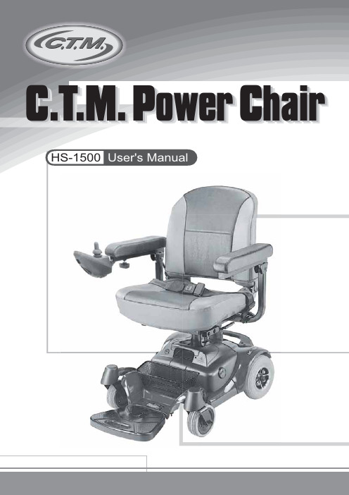
C.T.M. Power ChairHS-1500User's ManualTABLE OF CONTENTSIntroduction Important Precautions Electromagnetic Interference and Warnings Identification of Parts Operating Your Power Chair Disassembling / Re-assembling Your Power ChairCharging the BatteriesCare and MaintenanceTroubleshooting Technical Specifications--------------------------------------------------------------1-------------------------------------------------2----------------------3-------------------------------------------------5-----------------------------------------8-----------11---------------------------------------------13---------------------------------------------14------------------------------------------------------16--------------------------------------------18Thank you and congratulations on purchasing your new C.T.M. Power Chair. It is designed to provide you with transportation indoors and outdoors.Chien Ti Enterprise Co., Ltd. is the manufacturer for the C.T.M. mobility power chair. We pride ourselves on providing safe and comfortable products. Our goal is to ensure your complete satisfaction with our product. We are certain that you will enjoy your C.T.M. power chair.Please read and observe all warnings and instructions given in the owner's manual before operating this power chair. Also, retain this booklet for future reference.If you have any questions, please contact your local dealer or: Toll Free : 1-866-466-8168 Tel : 909-590-1388 Fax : 909-590-3365 E-Mail:***********************:// or your local dealer:Only one person at a time can ride a C.T.M. Power chair.Maximum load is 115 kg / 253 lbs.Turn off the power before getting on or off your power chair.Always drive carefully with your feet on the footplate and be aware of others in your area. Always use pedestrian crossings where possible. Take extreme care crossing roads. Do not drive on slopes exceeding 6 degrees, and take extreme care when turning on slopes.Do not use full power when turning sharp corners.Take great care and use low speeds for backing up, riding downhill, over uneven surfaces and curb climbing.The power chair may not operate well in high humidity.Never put your power chair in neutral on slopes.Follow all traffic laws when you ride in the vicinity of public roads.CAUTION: It is very important that you read this information regarding the possible effects of Electromagnetic Interference on your power chair.Powered wheelchairs and motorized scooters may be susceptible to electromagnetic interference (EMI), which is interfering electromagnetic energy (EM) emitted from sources such as radio stations, TV stations, amateur radio (HAM) transmitters, two-way radios, and cellular phones. The interference (from radio wave sources) can cause the power chair to release its brakes, move by itself, or move in unintended directions. It can also permanently damage the power chair control system. The intensity of the interfering EM energy can be measured in volts per meter (V/m). Each power chair can resist EMI up to a certain intensity. This is called its "immunity level." The higher the immunity level, the greater the protection will be. At this time, current technology is capable of achieving at least a 20 V/m immunity level, which would provide useful protection from the more common sources of radiated EMI. The immunity level of this product is 20 (V/m).There are a number of sources of relatively intense electromagnetic fields in the everyday environment. Some of these sources are obvious and easy to avoid. Others are not apparent and exposure is unavoidable. However, we believe that by following the warnings listed below, your risk to EMI will be minimized.The sources of radiated EMI can be broadly classified into three types:1.Hand-held portable transceivers (transmitters-receivers) with the antenna mounted directly on the transmitting unit. Examples include: citizens band (CB) radios, "walkie talkie," security, fire, and police transceivers, cellular telephones, and other personal communication devices.2.Medium-range mobile transceivers, such as those used in police cars, fire trucks, ambulances, and taxis. These usually have the antenna mounted on the outside of the vehicle.3.Long-range transmitters and transceivers such as commercial broadcast transmitters (radio and TV broadcast antenna towers) and amateur (HAM) radios.Because EM energy rapidly becomes more intense as one moves closer to the transmitting antenna (source), the EM fields from hand-held radio wave sources (transceivers) are of special concern. It is possible to unintentionally bring high levels of EM energy very close to the power chair control system while using these devices. This can affect power chairmovement and braking. Therefore, the warnings listed below are recommended to prevent possible interference with the control system of the power chair.Power Chair Electromagnetic InterferenceWarningsElectromagnetic interference (EMI) from sources such as radio and TV stations, amateur radio (HAM) transmitters, two-way radios, and cellular phones can affect the power chair.Following the warnings listed below should reduce the chance of unintended brake release or power chair movement, which could result in serious injury.1.Do not operate hand-held transceivers (transmitters-receivers), such as citizens band (CB) radios, or turn ON personal communication devices, such as cellular phones, while the power chair is turned ON;2.Be aware of nearby transmitters, such as radio or TV stations, and try to avoid coming close to them;3.If unintended movement or brake release occurs, turn the power chair OFF as soon as it is safe;4.Be aware that adding accessories or components, or modifying the power chair, may make it more susceptible to EMI; and5.Report all incidents of unintended movement or brake release to the distributor listed on the inside front cover of this manual. Note whether there is a source of EMI nearby.Electromagnetic Interference and WarningsImportant Information1.20 volts per meter (V/m) is a generally achievable and useful immunity level against EMI (as of May 1994). The higher the level, the greater the protection.2.The immunity level of this product is 20 (V/m).Armrest Width Adjustment ThumbscrewsFree-Wheeling LeverPower Reserve IndicatorOn/OffSwitchHornButton Speed Control Switch Release Lever Seat LockRear ReflectorsFigure 1 - HS-1500 Power Chair Front ViewFigure 2 - HS-1500 JoystickFigure 3 - HS-1500 Power Chair Rear ViewBefore attempting to drive this power chair on your own, it is important that you familiarize yourself with the controls and how they operate.Super ResponsiveDigital Joystick ControllerFlip Up ArmrestSwivel SeatLow Profile Cast Aluminum Wheelswith Multi-Terrain TiresOne-PieceBattery PackAdjustableFigure 4Speed Control SwitchBy pressing the right switch, you can increase the speed. Pressing the left switch will decrease the speed.Power Reserve IndicatorThere are LED Power Reserve lights on the joystick. When all LED lights are on,the batteries are fully charged. When a few of the lights are lit, the batteries need to be recharged.These lights also act as Self Diagnostic Warning Lights. When they flash, there is a problem with the power chair. See page 16 for more information.Joystick Length Extension KnobLoosen the knob to adjust the joystick length.When charging your power chair, use the power cord provided. To correctly charge your power chair, connect one end to the power chair charging socket and the other end to a wall outlet. See Charging the Batteries, page 13 for further instructions.Armrest Width Adjustment ThumbscrewsLoosen the two thumbscrews to adjust the armrest width; tighten again to lock in the desired position.Armrest Height Adjustment ScrewBy adjust screw (X1) to a comfortable position.Figure 5X1XFree-Wheeling LeverWhen the lever is in the N (Neutral) position, the power chair can be moved without power. When the lever is in the D (Drive) position, the power chair can be driven. Normal position is D.Seat Rotation LeverPull the seat rotation lever up to adjust seat's turning angle, also can lift up the seat. Do not turn the seat more the 180 degree due to length of joystick cable.Seat Lock Knob & PinTurn seat lock knob counterclockwise to loose. Turn it clockwise to lock seat in position. Remove the battery pack to locate the seat lock pin. There are three holes on seat post to adjust seat height. Be sure lock pin is fully inserted at its new height and knobFigure 6Figure 7This is to protect your power chair from any excess current within the electrical parts. If the power chair suddenly stops, pushing the circuit breaker back in will help resolve this problem.Anti-Tip WheelsAdded safety feature to keep chair from tipping over.Free-Wheeling LeversBefore beginning your journey with your new power chair, make sure that the power chair is on a level surface and clear of any obstacles. Although your power chair is able to climb slopes it is safer to practice on a level surface.1.Before operating your power chair, check the following:freewheeling lever is on D.speed control switch is at the lowest speed (repeatedly pressed left switch).2.Sit on the chair and fasten the seatbelt.3.When turning on the button on the joystick, all power reserve LED lights should be lit. All power reserve lights should not be flashing.4.While resting your arms on the armrests, the joystick should be within reach. By pushing the joystick slightly forward, the power chair will move forward slowly. Pushing the joystick fully forward, it will move at normal speed. Adjusting the speed control switch will also decrease and increase the speed. Also, with the joystick you are able to turn the chair 360o. When the joystick is released and back in the neutral position, the chair will stop.Figure 95.Practice driving where there are no obstacles. Start at the slowest speed and move forward and backward; make some turns. As you get more comfortable you can increase the speed by pressing the speed control switch repeatedly.6.When the power reserve Indicator is lit in only a few sections, you should plan to recharge the batteries very soon.Figure 10Figure 117.If the power chair suddenly stops and does not function, locate the circuit breaker at the rear of the power chair. Push it in and try the power chair again.8.When you are finished driving your power chair, turn the power off before getting out. It is recommended that you lift the armrest and get out to the side, for safety.Keep in mind these rules9.If you are finished riding for the day, immediately recharge the batteries.See CHARGING THE BATTERIES on page 13.Use your power chair only where it would be safe to walk.Use low speeds for reverse, downhill, ramps, curbs, or uneven surfaces.Other Operating InformationHill climbing: You may need to use a higher speed. For a higher speed, press the right speed control switch repeatedly.Down slopes:To proceed down steep slopes slowly, press the left speed control switch.This enables driver control when the speed is set at a slower motion.However, your power chair will not self accelerate down hills due to theautomatic braking taking effect should you attempt to drive too fast.Circuit BreakerCurb climbing: Approach slowly at right angles to the curb. A direct approach is needed. Do not attempt curb climbing greater than a 0.9" curb.If the Self-Diagnostic Warning Lights start to flash, identify the problem from the chart on page 16 and take action.If the power chair breaks down and must be moved aside, please follow these directions:1.Get off the power chair.2.Push the free-wheeling lever to N.3.Move the power chair slowly to a safe location.4.Put the free-wheeling lever back to D.Figure 12Unplug the Joystick Cable Connector (A) at the rear of the power chair. (See Fig. 11)Pull the Seat Rotation Lever (B) underneath the front part of the seat to unlock. Lift Seat (C) up to remove. (See Fig. 12)Remove the Basket by turning and removing the center Rivet (D). (See Fig. 13)Remove the Battery Pack (E) by holding the Battery Pack with one hand and the other hand pushing the Release Lever (F) to the rear of the chair. (See Fig. 14)Taking apart your power chair enables you to save space when keeping it in storage or to carry it along in your vehicle when going away from home. Having the power chair disassembled is easier than ever since no tools are required. To ensure your safety,please have the freewheeling lever to D to engage the motor.Figure 13Figure 14Figure 15Figure 16(A)(C)(D)(E)(F)(B)Figure 17Figure 18Detach the chair frame by holding the Seat Post (G) with one hand, the other hand pushing the Release Lever to the rear of the chair Lift the seat post to separate the Front Frame Assembly (H) from the Rear Frame Assembly (I). (See Fig. 15)Once all the parts have been disassembled, you are now able to put the pieces in storage or in a vehicle for transportation. (See Fig. 16)Re-assemble To re-assemble your power chair, you can repeat the disassembly directions in reverse.(G)(I)(H)Your C.T.M. power chair is equipped with two, service free 12V 14Ah rechargeable batteries and one 24V/2A on-board charger. Batteries must be charged before using the power chair for the first time and recommended to be charged up to 8 - 14 hours after each day's use. Be sure the power switch is in the OFF position and the free-wheeling lever is in the "D" position. 1.Insert the battery charger cord into the charging socket on the joystick.The time needed to recharge will vary depending on the depletion of thebatteries. Charging for longer than necessary will not harm the batteries.2.Plug the other end of the power cable into a standard electrical wall outlet.3.Once the batteries are fully charged, the light on the charger will change to green, please unplug the power cord from the wall outlet and the power chair. The power cord should be stored in a safe and dry location until it will be used again.4.If after charging your power chair over 8 - 14 hours and it does not function, please check: fuse is not burned out the power chair is turned off circuit breaker is pushed in if none of these is a problem, contact your authorized dealer.Keep in mind these rulesFully charge batteries at least once a month, more if you use the power chair regularly.Charge after each trip exceeding 3 kilometers / 1.86 miles.If storing your power chair for some time (one month or more) make sure that the batteries are fully charged, and on returning, charge them again before using the power chair.Batteries will only give the maximum performance after the power chair has been used,and the batteries have been recharged up to 10 times.For safety, please follow the guidelines below.1.DO NOT use the charger if the power cord is damaged.2.DO NOT use an extension cord when charging your batteries. A risk of fire and/or electric shock could be encountered.3.DO NOT take apart the charger, as this will void the warranty.Figure 19Taking care of your power chair will keep it in top-notch condition. It is recommended that you have your dealer provide preventative maintenance service of your power chair on a regularly basis. Here are a few maintenance guidelines:BODY COVER:If your power chair is dirty, use a damp or lightly soapy cloth to wipe it down. Do not use running water to wash or rinse the power chair in order to protect the electrical parts. Polish with an automotive liquid polish.SEAT AND ARMRESTS:The seat material used by C.T.M. is a product of high quality and will remain in good condition for many years if treated responsibly. Using a damp cloth helps clean the upholstery greatly. Please note that using the power chair outdoors can lead to sun damage of the upholstery material. Since this is a normal wear and tear condition, it is not covered under the warranty.SEAT BELT:A damp cloth with mild soapsuds should only be used to clean the seat belts. Wipe the seat belts gently removing any debris on it. Do not use any chemical products to clean the seat belts as the fabric will be weakened.FLAT SPOT (for solid tires only):During the storage period, a flat spot may occur on solid tires. Weather conditions and storage period could determine the condition of flat spots. By driving the power chair 20 to 30 minutes, flat spots can be eliminated.TIRE PRESSURE (for air-filled tires only):The condition of the tires and maintenance of the specified tire pressures not only influence tire life but also road safety to a very considerable extent. Incorrect pressuresare often a cause of tire problems and could result in an accident. The recommendedtire pressure is 35 lbs.TIRE TREAD:Inspect the tires frequently for any signs of damage, unusual wear and sufficient tread depth. Thread depth should not be allowed to drop below 1 mm.ELECTRICAL CONNECTIONS:.Verify the battery terminals and all plug connectors are secured and firmly attached. Ifthe battery terminals are corroded, please contact your dealer for replacement.HARDWARE:Check that all hardware exist and are securely fastened. Replace any missing hardwareby contacting your dealer for information of parts.Additional InformationSTORING:Also between uses, your power chair is best stored in a dry location at room temperature.3456Battery Fault Left Motor Fault Right Park Brake Fault Try charging the batteries.Batteries may require replacing.Check the batteries and cabling.Check the left motor, connectionsand cabling.Check the right motor, connectionsand cabling.Check the left park brake motor,connections and cabling.Check the right park brake motor,connections and cabling.Here are some suggestions about solving problems you may have with your power chair.There are 10 LED Self-Diagnostic Warning Lights on the Control Panel. To check the Self-Diagnostic Warning Lights, turn the power chair on and count the number of flashes.If the programmable parameter, Motor Swap, has been changed, then left and right hand references in this table will need transposing.Problem: All LED lights on joystick flash constantly.Solution: Both Right and Left motors are on Neutral.Power chair will not move when the power is turned on:1.Check the Battery Level Indicator on the joystick. All the LED lights should be on.2.Check the Self-Diagnostic Warning Light. It should be steady. If it is flashing, see the chart on page 16 for the problem identification.3.Check all electrical connections to be sure they are tight.4.Verify the batteries are connected correctly.5.If none of these suggestions correct the problem, contact your authorized dealer.If charging your power chair over 14 hours and the light on the charger does not change to green, then contact your authorized dealer.Please note that your power chair is equipped with a controller that constantly checks the drive system for a safe and enjoyable ride. If an error occurs, the Battery Level Indicator will provide you an indication of the problem by way of flashing lights.Wheels: RearWeight w/ BatteriesMax. SpeedWeight CapacityGround ClearanceGrade ClimbableCurb ClimbingTurning RadiusSeat Width8"105.4 lbs 4 mph 253 lbs 1.6"6 degree 0.9"27.4"Electro-Mechanical 18.5"(Issue A 10/02/2014 )。
VarioStar 1500焊机说明书

VarioStar 1500/ 2500/3100操作说明书配件明细MIG/MAG焊机尊敬用户介绍非常感谢您选择福尼斯(Fronius),祝贺您购买福尼斯(Fronius)生产的新技术的高端产品!本操作手册将帮助您更好地使用新设备。
仔细地研读本手册,您很快会熟知福尼斯(Fronius)产品具有的许多强大功能,将真正体现出您采购本设备的最大优势。
敬请注意专用安全规则,并遵守!这样将确保使用中更安全。
当然,要仔细善待您的产品,可延长产品使用寿命和可靠性-也是体现最佳优势的基本要求。
安全规则危险!表示紧急危险情况,如不避免,将导致死亡或严重伤害。
此标志限于许多极度境遇,不用于物品损害,除非有人员伤害卷入的情况警告!表示潜在的危险情况,不避免,能导致死亡或严重伤害。
此标志不用于物品损害,除非有人员伤害卷入的情况。
小心!表示潜在的危险情况,不避免,可能导致次要或中度伤害。
此标志也用来警惕可引起物品损坏类的不安全行为。
注意!表示存在能影响焊接效果和设备损坏的风险的情况重要!表示实用经验提示和其他有用的特殊功能,不是有害和危险的标志。
上面出现的符号,必须更加注意相关内容!概述本设备是依照技术水准、符合所有安全规范生产。
不过,非法操作或滥用仍然会导致如下危险:——使用人员或他人的生命安全及安康——设备及用户/使用者的其他物品——设备工作效能任何启动、操作、维修及维护本设备的人员必须具备:——相应资质——熟知焊接——理解并正确执行本手册使用说明操作手册必须随时保留在设备所在场所。
除操作手册之外,常规可用的、当地事故预防和环境保护规则的复件必须能随时查到,当然也要实际遵守。
设备上的所有安全说明、危险和警告——必须保持清晰易读——不允许损坏和擦除——不允许遮掩、糊住或涂画设备上的安全说明、危险和警告,可参阅机器操作手册前部的“一般说明”任何可能影响机器安全的故障必须立即解决,然后才能给设备上电。
注意安全!限定用途设备仅可用来进行“约定用途”的工作。
智能1500智能备电源的产品介绍说明书
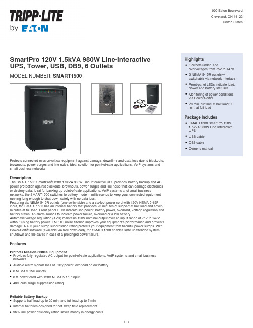
SmartPro 120V 1.5kVA 980W Line-Interactive UPS, Tower, USB, DB9, 6 OutletsMODEL NUMBER:SMART1500Protects connected mission-critical equipment against damage, downtime and data loss due to blackouts, brownouts, power surges and line noise. Ideal solution for point-of-sale applications, VoIP systems and small business networks.DescriptionThe SMART1500 SmartPro® 120V 1.5kVA 980W Line-Interactive UPS provides battery backup and AC power protection against blackouts, brownouts, power surges and line noise that can damage electronics or destroy data. Ideal for backing up point-of-sale applications, VoIP systems and small business networks, the SMART1500 switches to battery mode in milliseconds to keep your connected equipment running long enough to shut down safely with no data loss.Featuring six NEMA 5-15R outlets (one switchable) and a six-foot power cord with 120V NEMA 5-15P input, the SMART1500 has an internal battery that provides 20 minutes of support at half load and seven minutes at full load. Front-panel LEDs indicate line power, battery power, overload, voltage regulation and battery status. An alarm sounds to indicate power failure, overload or a low battery.Automatic voltage regulation (AVR) maintains 120V nominal output over an input range of 75V to 147V without using battery power. EMI/RFI noise filtering improves your equipment’s performance and prevents damage. A 480-joule surge suppression rating protects your equipment from harmful power surges. With PowerAlert® software (available via free download), the SMART1500 enables safe unattended system shutdown and file saves in case of a prolonged power failure.FeaturesProtects Mission-Critical EquipmentProvides fully regulated AC output for point-of-sale applications, VoIP systems and small business networksqAudible alarm signals loss of utility power, overload or low batteryq6 NEMA 5-15R outletsq6 ft. power cord with 120V NEMA 5-15P inputq480-joule surge suppression ratingqReliable Battery BackupSupports half load up to 20 min. and full load up to 7 min.qInternal batteries designed for hot-swap field replacementq96% line-power efficiency rating saves money in energy costsq HighlightsCorrects under- andovervoltages from 75V to 147V q6 NEMA 5-15R outlets—1switchable via network interface qFront-panel LEDs indicate load, power and battery statusesqMonitoring of power conditionsvia PowerAlert®q20 min. runtime at half load; 7min. at full loadqPackage IncludesSMART1500 SmartPro 120V1.5kVA 980W Line-InteractiveUPSqUSB cableqDB9 cableqOwner’s manualqSpecificationsCold-start capability enables turn-on in battery mode during blackoutsqLoad Bank with Switchable OutletCan control one outlet remotely to reboot equipment or shed nonessential loadsq Automatic Voltage Regulation (AVR)Maintains 120V nominal output over input range of 75V–147V without using battery powerq EMI/RFI Line Noise FilteringRemoves electromagnetic and radio frequency interference that can disrupt or damage equipment’s performanceq LED IndicatorsFront-panel LEDs indicate line power, battery power, overload, voltage regulation and battery statusq Communications PortsUSB & Serial ports enable data-saving unattended shutdown when used with PowerAlert software,available via FREE download from /products/power-alertq Small-Footprint Tower HousingMounts on wall with optional UPSWM accessoryq© 2023 Eaton. All Rights Reserved. Eaton is a registered trademark. All other trademarks are the property of their respective owners.。
电磁流量计使用说明书

LDC型电磁流量计使用说明书1 产品用途与适用范围特点:■可编程频率低频矩形波励磁,提高了流量测量的稳定性,功率损耗低;■采用16位嵌入式微处理器,运算速度快;精度高;■全数字量处理,抗干扰能力强,测量可靠,精度高,流量测量范围度可达1500 : 1;■超低EMI开关电源,适用电源电压变化范围大;抗EMC性能好;■全汉字菜单操作,使用方便,操作简单,易学易懂;■高清晰度背光LCD显示;■具有双向流量测量、双向总量累计功能,电流、频率具备双向输出功能;■内部具有三个积算器可分别显示正向累计量、反向累计量及差值积算量;■具有RS485或RS232C数字通讯信号输出;■具有电导率测量功能,可以判别传感器是否空管;■具有自检与自诊断功能;■采用SMD器件和表面安装SMT技术,电路可靠性高;■仪表内部设计有不掉电时钟,可记录16次掉电时间;1.2 主要用途电磁流量计用来测量封闭管道中导电流体的体积流量;广泛地适用于石油化工、钢铁冶金、给水排水、水利灌溉、水处理、环保污水总量控制、造纸、医药、食品等工、农业部门的生产工艺过程流量测量和控制;适用于导电液体的总量计量;1.3 正常工作条件环境温度:分体型–10~+ 60℃;相对湿度:5%~90%;供电电源:单相交流电 85~265V,45~63Hz;功率:小于20W;试验参比条件环境温度:20℃±2℃相对湿度:45%~85%电源电压:220±2%电源频率:50Hz±5%谐波含量小于5%;预热时间:30min2 产品型式电磁流量计有分体型和一体型两种结构形式;3 工作原理电磁流量计的工作原理基于法拉第电磁感应定律;当一个导体在磁场内运动,在与磁场方向、运动方向相互垂直方向的导体两端,会有感应电动势产生;电动势的大小与导体运动速度和磁感应强度大小成正比;在图1-1中,当导电流体以平均流速V s m /通过装有一对测量电极的一根内径为D m 的绝缘管子流动时,并且该管子处于一个均匀的磁感应强度为BT 的磁场中;那么,在一对电极上就会感应出垂直于磁场方和流动方向的电动势E;由电磁感应定律可写做1式: V D B E ⋅⋅=V (1)通常,体积流量可以写作V D q4π=s m / (2)由公式1和2可得到:)(4s m B E D q π= (3)因此电动势可表示为:)(q v V D B E π4= (4)当B 是个常数时,公式3中k B D =14π,公式3改写为:)/(s m kEq = 可见,流量q 与电动势E 成正比;图1-2 转换器电路结构图 转换器电路结构电磁流量转换器一方面向电磁流量传感器励磁线圈提供稳定的励磁电流,以达到B 是个常量;同时把传感器感应的电动势放大、转换成标准的电流信号或频率信号,便于流量的显示、控制与调节;图1-2所示为转换器电路结构;4 技术性能指标执行标准JB/T 9248-1999 电磁流量计;图 电磁流量计工作原理基本参数与性能指标传感器公称通经:3、6、10、15、20、25、32、40、50、65、80、100、125、150、200、250、300、350、400、450、500、600、700、800、900、1000、1200、1400、1600、1800、2000、2200、2400、2600、2800、3000;流量测量范围流量测量范围上限值的流速可在s~15m/s范围内选定,下限值的流速可为上限值的1%;参比条件下流量计精确度见表;:设定量程m/s 表VS重复性误差测量值的±%;电流输出a)电流输出信号:双向两路,全隔离0~10mA / 4~20mA;b)负载电阻:0~10mA时,0~Ω;4~20mA时,0~750Ω;C基本误差:在上述测量基本误差基础上加±10μA;频率频率输出:正向和反向流量输出,输出频率上限可在1~5000Hz内设定;带光电隔离的晶体管集电极开路双向输出;外接电源不大于35V,导通时集电极最大电流为250mA;脉冲输出脉冲输出:正向和反向流量输出,输出脉冲上限可达5000cp/s;脉冲当量为~cp;脉冲宽度自动设置为20ms或方波;带光电隔离的晶体管集电极开路输出;外接电源不大于35V,导通时集电极最大电流为250mA;流向指示输出本流量计可测正反方向的流体流动流量,并可以判断出流体流动的方向;规定显示正向流量时输出+10V高电平,反向流体流动输出0V的低电平;报警输出:两路带光电隔离的晶体管集电极开路报警输出;外接电源不大于35V,导通时集电极最大电流为250mA;报警状态:流体空管、励磁断线、流量超限;串行通讯:可选RS232C或RS485串行通讯接口、具有防雷击保护;阻尼时间:在0~100s90%时间分档可选;电气隔离:模拟输入与模拟输出间绝缘电压不低于500V;模拟输入与报警电源间绝缘电压不低于500V;模拟输入与交流电源间绝缘电压不低于500V;模拟输出与交流电源间绝缘电压不低于500V;模拟输出与大地之间绝缘电压不低于500V;脉冲输出与交流电源间绝缘电压不低于500V;脉冲输出与大地间绝缘电压不低于500V;报警输出与交流电源间绝缘电压不低于500V;报警输出与大地间绝缘电压不低于500V;键盘定义与显示方表键盘定义与液晶显示图a方表键盘定义与小液晶显示图b方表键盘定义与大液晶显示圆表键盘定义与大液晶显示图c圆表键盘定义与大液晶显示说明:一直按住“复合键”数秒,进入输入密码“00000”状态,输入“19818”,再按住“复合键”数秒,进入选择操作菜单进行参数设置;如果想返回运行状态,请按住“▲”键数钞;方表剖面图方表小液晶无通讯分体式剖面图图a方表小液晶无通讯分体式剖面图注:1上盖体;2小液晶;3按键电缆平面朝液晶/16线;4下盖体;5通讯板安装位置;6显示电缆平面朝液晶/20线;7接线端子;8分体挂钩;方表大液晶有通讯分体式剖面图图b方表大液晶有通讯分体式剖面图注:1上盖体;2键线;3大液晶;4按键电缆平面朝液晶/16线;5下盖体;6通讯板;7显示电缆平面朝液晶/20线;8通讯线平面朝通讯片/16线;9通讯信号线2线;10接线端子;11分体挂钩;接线方表端子接线与标示图方表接线端子图方表各接线端子标示含义如下:方表信号线的处理与标示图方表信号线的处理与标示圆表端子接线与标示图a圆表接线端子图图b圆表接线端子图圆表各接线端子标示含义如下:I+:流量电流输出COM : 电流输出地 P+: 双向流量频率脉冲输出 COM : 频率脉冲输出地AL : 下限报警输出 AH : 上限报警输出 COM : 报警输出地 FUSE : 输入电源保险丝 T 1+: 通讯输入 T 2-: 通讯输入 L 1: 220V24V 电源输入 L 2: 220V24V 电源输入 圆表信号线的处理与标示图 圆表信号线的处理与标示圆表信号线标示如下:白色双股线: 红色12黑色12芯线黑色双股蔽线:红色10芯线接“信号1”蓝色13芯线接“信号2”屏蔽线接“信号地”流量信号线分体型转换器与传感器配套使用时,对被测流体电导率大于50μS/cm的情况,流量信号传输电缆可以使用型号为RVVP2×32/的聚氯乙烯护套金属网屏蔽信号电缆;使用长度应不大于100m;信号线与传感器配套出厂;信号线的处理方表可按图进行,圆表可按图进行;本转换器提供有等电位激励屏蔽信号输出电压,以降低电缆传输的分布电容对流量信号测量的影响;当被测电导率小于cm50 或长距离传输时,可使用具有等电位屏蔽的双S/芯双重屏蔽信号电缆; 例如STT3200专用电缆或BTS型三重屏蔽信号电缆.;励磁电流线励磁电流线可采用二芯绝缘橡皮软电缆线,建议型号为YHZ-2×1mm2;励磁电流线的长度与信号电缆长度一致;当使用STT3200专用电缆时,励磁电缆与信号电缆合并为一根;输出与电源线所有输出与电源线由用户根据实际情况自备;但请注意满足负载电流的要求;注意:当接线端子旁边的DIP开关拨向ON的位置时,由转换器内部向隔离的OC门频率输出PUL+、PUL-、报警输出ALM+、ALM-及状态控制INSW提供+28V电源和10kΩ上拉电阻;因此,在使用频率输出与传感器配套试验时,可将DIP开关拨至ON,从PUL+和PCOM接线引出频率信号;脉冲电流输出、报警电流输出外接供电电源和负载见图;使用感性负载时应如图加续流二极管;图a电流输出接线图图b电磁计数器接线图c电子计数器接线图d报警输出接线图e表内OC门连接方式接地转换器壳体接线端子PE应采用不小于接地铜线接大地;接地电阻不大于10Ω;5仪表参数设置仪表有两个运行状态:自动测量状态参数设置状态仪表上电时,自动进入测量状态;在自动测量状态下,仪表自动完成各测量功能并显示相应的测量数据;在参数设置状态下,用户使用四个面板键,完成仪表参数设置;键功能自动测量状态下键功能下键:循环选择屏幕下行显示内容;上键:循环选择屏幕上行显示内容;复合键 + 确认键:进入参数设置状态;确认键:返回自动测量状态;测量状态下,LCD显示器对比度的调节:小液晶是通过“复合键 + 上键”或“复合键 + 下键”按下数秒钟;大液晶是通过调节大液晶背面的电位器来实现;参数设置状态下键功能下键:光标处数字减1;上键:光标处数字加1;复合键 + 下键:光标左移;复合键 + 上键:光标右移;确认键:进入/退出子菜单;确认键:在任意状态,连续按下两秒钟,返回自动测量状态;注:1使用“复合键”时,应先按下复合键再同时按住“上键”或“下键”;2在参数设置状态下,3分钟内没有按键操作,仪表自动返回测量状态;3流量零点修正的流向选择,可将光标移至最左面的“+”或“-”下,用“上键”或“下键”切换使之与实际流向相反;4流量的单位选择,可将光标移至“流量量程设置”菜单的原显示的流量单位下,然后用“上键”或“下键”切换使之符合需要;参数设置功能键操作要进行仪表参数设定或修改,必须使仪表从测量状态进入参数设置状态;在测量状态下,按“复合键 + 确认键”出现状态转换密码0000,根据保密级别,按本厂提供的密码对应修改;再按“复合键 + 确认键”后,则进入需要的参数设置状态;仪表设计有6级密码,其中4级用户可以自行设置密码值,最高2级为固定密码值,6级密码分别用于不同保密级别的操作者;参数设置菜单L-mag共有50个参数,使用仪表时,用户应根据具体情况设置各参数;L-mag参数一览表如下:参数设置菜单一览表注:参数编号40~45项为掉电时间记录功能,无掉电功能转换器无此参数项;仪表参数说明仪表参数确定仪表的运行状态、计算方法、输出方式及状态;正确地选用和设置仪表参数,可使仪表运行在最佳状态,并得到较高的测量显示精度和测量输出精度;仪表参数设置功能设有6级密码;其中,1~5级为用户密码,第6级为制造厂密码;用户可使用第5级密码来重新设置第1~4级密码;无论使用哪级密码,用户均可以察看仪表参数;但用户若想改变仪表参数,则要使用不同级别的密码;第1级密码出厂值0521:用户能察看所有的参数;第2级密码出厂值3210:用户能改变1~20仪表参数;第3级密码出厂值6108:用户能改变1~22仪表参数;第4级密码出厂值7206:用户能改变1~24仪表参数;第5级密码固定值:用户能改变所有的参数;建议由用户较高级别的人员掌握,第5级密码;第4级密码,主要用于设置总量清“0”密码;第1~3级密码,由用户决定何级别的人员掌握;测量管道口径用户可根据测量流量范围的不同选择配套的工程通径为3~3000mm范围的电磁流量计;仪表量程设置仪表量程是指流量测量的上限流量值满量程;上限流量值是针对输出信号和百分比显示而言的;它与电流输出上限值和频率脉冲输出上限值及100%显示值相对应;与之相关联的还有用百分比流量表示的小信号切除和超限报警;本转换器的流量显示与流速显示在表规定的范围内不受流量量程的限制;在仪表量程设置参数中选择流量显示单位,仪表流量显示单位有:L/s、L/min、L/h、m3/s、m3/min、m3/h,用户可根据工艺要求和使用习惯选定一个合适的流量显示单位;注意:仪表用5位有效数字显示流量值,末位数值的后面显示有流量的单位;微处理机能够在选择的流量单位不合适时,向操作者显示提示出设置错误造成的“上溢”或“下溢”;例200 mm 口径,选l/h 为流量显示单位,当1m/s流速时,流量为113097 L/h,超出5位数,造成“上溢”,此时流量单位应选择m3/s、m3/min和m3/h;而3 mm口径,选择m3/s,流量为s,在5位显示数字下,根本无法显示出有效数字,造成“下溢”,此时;此时流量单位应选择L/s、L/min或L/h;测量阻尼时间长的测量阻尼时间能提高仪表流量显示稳定性及输出信号的稳定性,适于具有流量调节的情况使用;短的测量阻尼时间可以加快测量反映速度,适于总量累计的脉动流量测量;测量阻尼时间的设置采用选择方式,用户选一个阻尼时间值即可;流量方向择向如果用户认为调试时的流体方向为正,而仪表显示为负,则将流量方向设定反向,反之亦然;流量零点修正在电磁流量传感器的测量管内充满导电流体,并且流体处于静止不流动,转换器已经对流量计的零点作了智能化处理;若所配传感器的零点超出转换器的智能处理范围,则需用户进行流量零点修正;流量零点是用流速表示的,单位为mm/s;转换器流量零点修正显示如下:显示中:上行FS 代表仪表零点测量值,下行显示是流量零点修正值;当FS 显示不为“0”时,应调修正值使FS=0;注意:若改变下行修正值,FS 值增加,需要改变下行数值的正、负号,使FS 能够修正为零;再次提醒:流量零点修正必须在电磁流量传感器的测量管内充满导电流体,并且流体处于静止不流动条件下进行;流量零点的修正值是传感器的校验常数值,应记入传感器的记录单与标牌;记入时传感器零点值是以mm/s为单位的流速值,其符号与修正值的符号相反;小信号切除点小信号切除点设置是用量程的百分比流量表示的;小信号切除时,用户可以选择同时切除流量、流速及百分比的显示与信号输出;也可选择仅切除电流输出信号和频率脉冲输出信号,保持流量、流速及百分比的显示;流量积算单位转换器显示器为10位计数器,最大允许计数值为95;使用积算单位为L 和m 3,并有、、、1L 和、、、、1m 3的倍率,可方便读出一段时间的累计流量;本转换器能够自动判断应使用的流量积算单位和倍率是否溢出;电流输出类型用户可在电流输出类型中选择0~10mA 或4~20 mA 电流输出;脉冲输出方式脉冲输出方式有频率输出和脉冲输出两种供选择;频率输出为连续方波;脉冲输出为矩形波脉冲串;频率输出多用于数字的瞬时流量测量和短时间总量累积;脉冲输出通过脉冲单位当量选择,可读出累计流量的容积值,多用于长时间直接容积单位的总量累积;频率输出和脉冲输出一般为OC门形式;因此,应外接直流电源和负载;具体见第节的图;脉冲单位当量脉冲单位当量指一个脉冲所代表的流量值,仪表脉冲当量选择范围为:在同样的流量下,脉冲当量小,则输出脉冲的频率高,累计流量误差小;仪表最高能输出5000cp/s的脉冲频率;用于机械式电磁计数器最高频率可达25次/秒;脉冲输出的最大脉冲宽度为20ms,高频时自动转换为方波;频率输出范围仪表频率输出范围对应于流量测量上限,即百分比流量的100%;频率输出上限值可在1~5999Hz范围内任意设置;空管报警允许仪表具有空管检测功能,若用户选择允许空管报警,则当仪表检测出空管状态时,即将仪表模拟输出、数字输出置为信号零,同时将仪表流量显示为零;空管报警阀值本产品的空管报警是用实测传感器中的电导率来做判断的;不同的流体具有不同的电导值电阻值,空管检测实际上是检测被测导电液体的电阻与实验导电液体电阻的比值液体的相对导电率是否超出阈值;超出阈值就意味着被测流体电导率远低于实验液体的电导率,相当于空管;空管报警阈值的默认值尾%;空管量程修正是为测量相对电导率而用的;在传感器充满试验液体情况下,修正系数使电导比为一个确定值,例如试验液体是水,其电导率约为100μS/cm,可修正为100%;当被测液体电导率为5μS/cm,相对的电导比则大约显示2000%;如果试验液体水的电导比修正为10%;那么,被测液体电导率为5μS/cm时相对电导比则大约显示200%;报警阈值设置是选择空管报警灵敏度范围的;最大阈值可设为%;如上例,被测液体显示2000%时发出报警,显示200%时不报警;因此欲使电导率5μS/cm在显示电导比200%时报警,需要设阈值在200%以下;空管报警量程的默认值为100%;上限报警允许用户选择允许或禁止;上限报警数值上限报警值以量程百分比计算,该参数采用数值设置方式,用户在0%~%之间设置一个数值;仪表运行时,当流量百分比大于该值时,仪表将输出报警信号;下限报警允许用户选择允许或禁止下限报警数值下限报警值以量程百分比计算,该参数采用数值设置方式,用户在0%~%之间设置一个数值;仪表运行时,当流量百分比小于该值时,仪表将输出报警信号;积算总量清零在该参数设置中,用户置入“积算总量清零”密码,仪表确认密码无误后,显示“允许进入”,即可完成积算量清零;同时将三个积算器清为零值,重新开始累积;“积算总量清零”密码可以在打开4级密码后,在“清积算量密码”菜单下置入您欲设置的“积算总量清零”密码,修改原来的“积算总量清零”密码;注意:请记下您的“积算总量清零”密码;传感器系数值仪表配套的传感器出厂校验单或产品标牌上标有“传感器系数”;用户应将“传感器系数”置入仪表的传感器系数值参数中;励磁方式选择转换器能向传感器提供三种励磁方式;用户可根据被测流体实际情况选择一种;通常可以使用方式1励磁,方式适合于大口径清洁水测量;注意,在哪种励磁方式下工作,就必须在哪种励磁方式下标定;流量标定系数该系数即转换器的标定系数;用户应使用统一的标准校验器对转换器标定;设定此系数,使所有的转换器保持一致性,以保证与传感器配套的互换性;仪表计算系数该系数为人为设定的系数;转换器内部计算时,总流量是测量流量乘以该系数值;例如,应用于具有仿真传感器的明渠测量潜水电磁流量计;电流满度修正转换器出厂的电流输出满度调节,使电流输出准确为10mA或20mA;出厂标定系数转换器制造厂用该系数使仪表励磁电流和信号放大器规格标准化;传感器编码传感器编码记载配套的传感器出厂时间和编号,以确保设置的传感器系数准确无误;转换器编码转换器编码记载转换器出厂时间和编号;时间年、月、日、时、分、秒带时钟功能用户使用5级密码进入,可改时间年、月、日、时、分、秒;用户密码1~4用户使用5级密码进入,可修改此密码;6 掉电时间记录带掉电功能仪表内部设计有不掉电时钟,能存储16次掉电记录;掉电记录时间格式为:掉电记录xxxx月xx日xx时xx分停至 xx月xx日xx时xx分;当16次掉电记录记满后,不再记录新的掉电时间;显示掉电记录按确认键,进入掉电记录显示方式,用增加键显示下个记录,用减少键显示前个记录,再按确认键返回流量显示方式;清除掉电记录先按住复合键,再按确认键,进入密码输入方式,置数:密码 4 + 11,再先按住复合键,再按确认键,将清除掉电记录;71/2工频使用说明1/2工频电磁和1/8工频电磁的区别仅在于前者的励磁频率高,从而要求传感器励磁系统的电流上升时间渡越时间尽可能小,以便使励磁电流在测量段达到稳定值;励磁电流渡越时间τ = L/R其中: L —— 励磁线圈电感;R —— 励磁线圈电阻;因此,减小L 或增大R 都会使τ减小;根据上面分析,改变传感器的励磁线圈接线法,如下图:R 1、R 2——外加电阻;R L1、R L2——励磁线圈电阻;a 将励磁线圈并联连接;b 加串联电阻R 1、R 2;c 使R 1 + R 2 ≤ 120Ω;使R 2 + R L2 ≤ 120Ω;d) 整个回路等效电阻小于60Ω;另:在1/2工频电磁转换器设计中,增加了传感器渡越时间测试功能;用户进入参数设置菜单,调到“仪表参数重置”项中,仪表将测试传感器渡起时间,用户每改变一次设置的数,仪表将自动测试一次渡越时间大约1分钟测完一次;若:渡越时间小于10ms,则励磁系统正常工作;若:渡越时间大于10ms,则励磁电流不能稳定;8 自诊断信息与故障处理电磁流量转换器的印刷电路板采用表面焊接技术,对用户而言,是不可维修的;因此,用户不能打开转换器壳体;智能化转换器具有自诊断功能;除了电源和硬件电路故障外,一般应用中出现的故障均能正确给出报警信息;这些信息在显示器右上方提示出“”惊叹号;在测量状态下,通过下键翻页,显示出故障内容如下:流量正常励磁报警空管报警故障处理:1 仪表无显示a)检查电源是否接通;b)检查电源保险丝是否完好;c)检查供电电压是否符合要求;d)检查显示器对比度调节是否能够调节,并且调节是否合适;e)如果上述前3项a、b、c都正常,第d项显示器对比度调节不能够调节请将转换器交生产厂维修;2)励磁报警a)励磁接线EX1和EX2是否开路;b)传感器励磁线圈总电阻是否小于150Ω;c)如果a、b两项都正常,则转换器有故障;3 空管报警a)测量流体是否充满传感器测量管;b)用导线将转换器信号输入端子SIG1、SIG2和SIGGND三点短路,此时如果“空管报警“提示撤消,说明转换器正常,有可能是被测流体电导率低或空管阈值及空管量程设置错误;c)检查信号连线是否正确;d)检查传感器电极是否正常:①使流量为零,观察显示电导比应小于100%;②在有流量的情况下,分别测量端子SIG1和SIG2对SIGGND的电阻应小于50kΩ对介质为水测量值;最好用指针万用表测量,并可看到测量过程有充放电现象;e)用万用表测量DS1和DS2之间的直流电压应小于1V,否则说明传感器电极被污染,应给予清洗;4)上限报警上限报警提示出输出电流和输出频率或脉冲都超限;将流量量程改大可以撤消上限报警;5 下限报警下限报警提示出输出电流和输出频率或脉冲都超限;将流量量程改小可以撤消下限报警;6)系统设置错误已在流量量程设置、流量积算单位设置和脉冲当量设置中作出智能判断并提示,方便修改设置;7)测量的流量不准确a)量流体是否充满传感器测量管;b)信号线连接是否正常;c)检查传感器系数、传感器零点是否按传感器标牌或出厂校验单设置正常;8)供应成套性按订货合同供应分体型或一体型结构的L-mag电磁流量转换器;随机文件包括:安装使用说明书、产品合格证、装箱单各一份;9)运输和贮存。
直流屏说明书(AH)
深圳市华信通技术有限公司目录一、概述----------------------------------------------------------------------- 1二、充电模块性能特点---------------------------------------------------- 3三、使用说明书--------------------------------------------------------- 6四、系统安装与保养---------------------------------------------------8运行示波图------------------------------------------------------------ 10 订货须知--------------------------------------------------------------- 11第一章概述1、引言目前我国各地的发电厂,水电站及35kv 、220kv、110kv等各类变电站,所使用直流电源设备(包括供给断路器分合闸用,后备电池充电以及2次回路的仪器表等低压设备用电)大部分采用的是相控电源或磁饱和式电源,由于受工艺水平和器件特性的限制。
上述电源存在很多不足之处,应该说已远远不能满足飞速发展的电力工程的需要。
而以体积小、重量轻、效率高、输出纹波极低,动态响应快,控制精度高,模块可叠加输出。
为特点的高频开关电源逐步取代相控电源已是大势所趋,特别是近几年来电力电子技术的迅猛发展以及功率、器件制造工艺技术提高,更使高频开关电源的可靠性,及适用面大大优于相控电源和磁饱和式电源。
2、应用范围GZD(W)系列直流电源柜适用于10~500kV变电站、发电厂和高层建筑、住宅小区等的配电室,以及小型自备发电厂,作为高压开关、继电保护、自动装置等的操作、控制电源和事故照明电源。
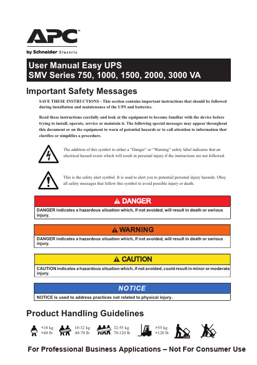
施耐德 APC SMV系列750, 1000, 1500, 2000, 3000 VA说明书

Important Safety InstructionsSAVE THESE INSTRUCTIONS - This manual contains importantinstructions that should be followed during installation and maintenance of the Easy UPS and batteries.Read these instructions carefully and look at the equipment to becomefamiliar with the device before trying to install, operate, service or maintain it. The following special messages may appear throughout this manual or on the equipment to warn of potential hazards or to call attention to information that clarifies or simplifies a procedure.The addition of either symbol to a “Danger” or “Warning” safetylabel indicates that an electrical hazard exists which will resultin personal injury if the instructions are not followed.This is the safety alert symbol. It is used to alert you to potentialpersonal injury hazards. Obey all safety messages that followthis symbol to avoid possible injury or death.Easy UPS SMV Series 750, 1000, 1500, 2000, 3000 VA2Product Handling GuidelinesSafety and General InformationGeneral safety• Adhere to all national and local electrical codes.• This UPS is for indoor use only. To prevent the risk of fire or electric shock, install in temperature and humidity controlled indoor area, free of conductive contaminants.Easy UPS must be installed indoor with controlled environment free of excessive dust, corrosive air or conductive dust. Keep out of direct sun light, water and heat sources.• Place the unit on the stable floor.• Be sure that the mains socket outlet that supplies the UPS is installed near the UPS and easily accessible. Avoid using extension cords.• UPS must be connected to an earthed mains socket outlet.• Connect the power cable directly to a wall outlet. Do not use surge protectors or extension cords.• CAUTION : This UPS is designed to satisfy the requirement of PCs only.• Do not connect printers, heaters, or copiers to the UPS.Battery safety<18 kg <40 lb 18-32 kg 40-70 lb 32-55 kg 70-120 lb >55 kg >120 lb• Servicing of user replaceable batteries should be performed orsupervised by personnel knowledgeable about batteries and requiredprecautions.NOTE: In this case batteries are not user replaceable.• When replacing battery the UPS must be off, and its AC inletunplugged.• CAUTION: Do not dispose of batteries in a fire. The batteries mayexplode.• CAUTION: Do not open or mutilate batteries. Released material isharmful to the skin and eyes and may be toxic.• CAUTION: A battery can present a risk of electrical shock and burns byhigh short-circuit current. Contact with any part of a grounded batterycan result in electrical shock. The following precautions should beobserved when working on batteries.–Remove watches, rings or other metal objects.–Use tool with insulated handles.–Wear rubber gloves and boots.–Do not lay tools or metal parts on top of batteries.–Disconnect the charging source prior to connecting or disconnectingbattery terminals.–Determine if battery is inadvertently grounded. If inadvertentlygrounded, remove source from ground. Contact with any part of agrounded battery can result in electrical shock. The likelihood of suchshock can be reduced if such grounds are removed during installationand maintenance.• CAUTION: The UPS contains internal batteries and may present ashock hazard even when disconnected from AC power.• CAUTION: Battery circuit is not isolated from AC input, hazardousvoltage may exist between battery terminals and ground. Test beforetouching.• CAUTION: Failed batteries can reach temperatures that exceed theburn thresholds for touchable surfaces.Radio Frequency WarningThis is a category C2 UPS product. In a residential environment, this product may cause radio interference, in which case the user may be required to take additional measures.Easy UPS SMV Series 750, 1000, 1500, 2000, 3000 VA3Package Contents4Easy UPS SMV Series 750, 1000, 1500, 2000, 3000 VARear Panel FeaturesEasy UPS SMV Series 750, 1000, 1500, 2000, 3000 VA5Front Panel FeaturesFront panel display6Easy UPS SMV Series 750, 1000, 1500, 2000, 3000 VAEasy UPS SMV Series 750, 1000, 1500, 2000, 3000 VA7Start UpConnect batteryThe battery connector is located on the rear panel. Refer to “Rear Panel Features” on page 5 for details.NOTE : Connect prior to operation.Disconnect prior to transportation. Turn off the UPS and remove input power cable before disconnecting the battery connector. Connect equipment and input power to Easy UPS1. Connect equipment to the battery backup outlets of Easy UPS.2. Plug the Easy UPS power cord directly into a wall outlet, not into asurge protector or power strip.3. Press the POWER ON /OFF button to turn on the unit.NOTE : The Easy UPS should charge the battery for at least 8 hours to ensure sufficient runtime.4. Press the POWER ON /OFF button in 1~3 seconds. Confirm that theEasy UPS is on and is providing power to outlets.Cold start the UPSUse the cold start feature to supply power to connected equipment from the UPS batteries when the UPS is off and there is no power utility.• Press the POWER ON /OFF button. The display panel will illuminate.• Press the POWER ON /OFF button again to supply battery power to the connected equipment.Connect and install management softwareEasy UPS is provided with management software forunattended operating system shutdown, UPSmonitoring, and UPS settings.Refer to for more information. SpecificationsModel SMV750I-MSX SMV1000I-MSXSMV1500AI-MSXSMV2000AI-MSXSMV3000AI-MSXInput SpecificationsVoltage220/230/240 V ACVoltage range165-290 V AC ± 5 V AC165-295 V AC ± 8 V AC Fuse8 A8 A12 A20 A25 A Frequency range45-65 Hz (auto sensing) ±1 HzOutput specificationsUPS capacity (total)750 V A/525 W1000 VA/700 W1500 V A/1050 W2000 V A/1400 W3000 V A/2100 WRated voltage230 VAC Transfer time Typical 2-6 ms, 12 ms max. Waveform Pure Sinewave BatteryType (Maintenance-free Lead acid)12 V /7 Ah x 212 V /7 Ah x 212 V /10 Ah x 212 V /7 Ah x 412 V /9 Ah x 4Charging time4-6 hours recover to 90% capacity PhysicalDimension (D x W x H)410 x 160 x 220 mm(16.1 x 6.3 x 8.7 in)455 x 180 x 240 mm(18 x 7.1 x 9.4 in)Weight withoutpackage13.6 kg17.8 kg23.5 kg25.2 kgPackaging Dimension (D x W x H)508 x 272 x 339 mm(20 x 10.8 x 13.3 in)604 x 319 x 414 mm(23.8 x 12.5 x 163 in)Easy UPS SMV Series 750, 1000, 1500, 2000, 3000 VA8Easy UPS SMV Series 750, 1000, 1500, 2000, 3000 VA 9Audible Indicators and Status IconsTroubleshootingUse the table below to solve minor installation and operation problems.ModelSMV 750I-MSX SMV 1000I-MSX SMV 1500AI-MSX SMV 2000AI-MSX SMV 3000AI-MSX Weight with package 16.6 kg20.75 kg26.9 kg28.9 kgEnvironment Operating,temperature and humidity 0-90% RH @ 0-40 °C (non-condensing)0-95% RH @ 0-40 °C (non-condensing)Noise level < 45 dB International Protection CodeIP20Problem and/or Possible Cause SolutionEasy UPS will not turn on The Easy UPS is not turned on.Press the POWER ON /OFF button to turn on the Easy UPS.The Easy UPS is not connected to AC power, there is no AC power available at the wall outlet, or the AC power is experiencing a brownout or over voltage condition.Be sure that the power cord is securely connected to the utility power outlet and AC power isavailable at the utility power outlet. Check that the wall outlet is switched on or input fuse works properly.10Easy UPS SMV Series 750, 1000, 1500, 2000, 3000 VAServiceIf the unit requires service, do not return it to the dealer. Follow these steps:1. Review the Troubleshooting section of the manual to eliminate commonproblems.2. If the problem persists, contact APC by Schneider Electric CustomerSupport.a.Note the model number and serial number and the date of purchase.The model and serial numbers are located on the rear panel of theunit.b.Call APC by Schneider Electric Customer Support and a technicianwill attempt to solve the problem over the phone. If this is notpossible, the technician will issue a Returned Material AuthorizationNumber (RMA#).c.If the unit is under warranty, the repairs are free.d.Service procedures and returns may vary internationally. Refer to theAPC by Schneider Electric website for country specific instructions.3. Pack the unit in the original packaging whenever possible to avoiddamage in transit. Never use foam beads for packaging. Damagesustained in transit is not covered under warranty.4. Always DISCONNECT THE UPS BATTERIES before shipping.The United States Department of Transportation (DOT), and theInternational Air Transport Association (IATA) regulations requirethat UPS batteries be disconnected before shipping. The internalbatteries may remain in the UPS.5. Write the RMA# provided by Customer Support on the outside of thepackage.6. Return the unit by insured, pre-paid carrier to the address provided byCustomer Support.Easy UPS SMV Series 750, 1000, 1500, 2000, 3000 VA11© 2020 APC by Schneider Electric. APC, the APC logo, and Easy UPS areowned by Schneider Electric Industries S.A.S., or their affiliated companies. All other trademarks are property of their respective owners.EN 990-9144811/2020WarrantyRegister your product on-line The standard warranty is two (2) years from the date of purchase. SEITstandard procedure is to replace the original unit with a factoryreconditioned unit. Customers who must have the original unit back due to the assignment of asset tags and set depreciation schedules must declaresuch a need at first contact with an SEIT Technical Support representative.SEIT will ship the replacement unit once the defective unit has beenreceived by the repair department, or cross-ship upon the receipt of a valid credit card number. The customer pays for shipping the unit to SEIT. SEIT pays ground freight transportation costs to ship the replacement unit to the customer.APC by Schneider Electric IT Customer SupportWorldwideFor country specific customer support, go to the APC by Schneider Electric website, .。
M、AH、HH型渣浆泵说明书
M、AH、HH 型渣浆泵使用、装配和维护说明书河北高通泵业安全须知〔一〕泵是一种即承压又传动的机器,在安装、操作和修理前及安装操作和修理期间,必需遵守所规定的安全措施。
辅机〔如电机、皮带传动装置、联轴器、高速箱、无级变速装置等等〕也要遵守这项安全措施,并在安装、操作和修理前参考有关规程。
〔二〕装皮带或联轴器之前,必需检查转动方向,由于不正确的转动方向将使泵在运转中损坏或个别零件的损坏。
〔三〕未经特地人员许可,不得使泵超出原来销售时规定的工况运转,否则将导致设备或人身事故。
〔四〕泵不行在较低或零流量点或在其他可能引起泵送介质汽化的状况下运转,否则将由于压力巨增而可能造成设备人身事故。
〔五〕修理或泵送期间,内部真空的泵必需隔离,假设不能完好隔离,可能使叶轮变为“飞轮”,从而造成设备和人身事故。
注释应备有包括液池、泵送管路、阀门、把握装置等等在内的系列安装图,以免错装给泵带来不利影响。
M、AH、HH 型渣浆泵使用、装配和使用说明书目录第一节:1、泵规格型号代号说明32、泵装配33、根底34、泵轴〔与电机轴〕对中35、管道36、启动47、修理58、备件79、润滑脂710、建议承受的润滑脂量和润滑周期8其次节:轴承装配说明B、C、D、E、F 和G 型托架9—14 第三节:轴承装配说明R、Rs、S、ST、T 和Tu 型托架15—18第四节:轴承组件试验说明书19第五节:托架装配说明书20第六节:泵头的组装说明书21—36第七节:叶轮间隙的调整37第八节:泵的拆卸38附表1:泵的根本零件号39附表2:装泵工具名目41第一节使用说明1、泵规格型号代号说明每台沃曼泵都有一个铭牌,钉在托架上,铭牌上印有泵规格号,泵的规格号由数字和字母组成,并排列如下:数字数字字母字母〔a〕〔b〕〔c〕〔d〕(a)、吸入口直径,以英寸表示,如1.5、2.4、10、20、36 等等。
(b)、吐出口直径,也以英寸表示,如1、1.5、3、8、18、36 等等。
海为 A Series卡型PLC-MPU用户手册说明书
Haiwell PLC User ManualA Series Card-type PLCPLC MPU User ManualContents1.Product Model List&Dimensions (3)2.Indicator Description (4)3.Power Supply Specification (4)4.Environmental specifications for Product (4)5.Digital Input(DI)Specification (4)6.Digital Output(DO)Specification (5)7.Analog Input(AI)Specification (5)8.Analog Output(AQ)Specification (5)9.Digital Input/Output(DI/DO)Wiring (5)10.Analog Input(AI)Wiring Diagram (6)11.Analog Output(AQ)Wiring Diagram (6)12.MPU Terminal Wiring Diagram (6)13.PLC Mounting and installation (6)14.Address Setting (7)15.Power Supply Wiring (7)1.Product Model List &Dimensions AC/AT/AH Series Model List &DimensionsAC series models Power Consumption(24VDC)Dimension(W ×H ×D)AC10S0R DC24V~0.2A MAX 40×95×65mmAC10S0T DC24V~0.2A MAX AC10S0P DC24V~0.2A MAX AC16S0R DC24V~0.2A MAX AC16S0T DC24V~0.2A MAX AC16S0P DC24V~0.2A MAX AC12M0R DC24V~0.15A MAX AC12M0T DC24V~0.15A MAX AC12M0P DC24V~0.15A MAX AT series modelsPower Consumption(24VDC)Dimension(W ×H ×D)AT16S0R DC24V~0.2A MAX 40×95×65mmAT16S0T DC24V~0.2A MAX AT16S0P DC24V~0.2A MAX AT12M0R DC24V~0.15A MAX AT12M0T DC24V~0.15A MAX AT12M0P DC24V~0.15A MAX AH series modelsPower Consumption(24VDC)Dimension(W ×H ×D)AH16S0R 0.2A MAX 40×95×65mmAH16S0T 0.2A MAX AH16S0P0.2A MAX1.Digital channel indicator8.Rail clip1.PWR:Power indicator,RUN:Running indicator,COM:Communication indicator,ERR:Error indicator 9.RS485terminal block2.Running switch 10.DC24V power supply terminal3.DIP switch 11.Module hook4.Ethernet port12.Module connection positioning hole 5.Terminal definition13.Module expansion port 6.Removable terminal block14.35mm DIN rail2.Indicator Description1PWR:Power indicator,green.Continuous ON-Power good;OFF-Power error.2RUN:Running indicator,green.Continuous ON-PLC is in running state;OFF-PLC was shutdown.3COM:Communication indicator,green.Flickering-PLC is in communicating state,the flicker frequency indicates the speed of the communication;OFF-No communication.4ERR:Error indicator,red.Continuous ON-Hardware failure;Flickering-Software failure;OFF-Normal state. According to the different states of the Error indicator,users are recommended to take the following actions:Reference processing mode Instruction information classification ERR indicator status Normal No errors No lightNormal,only remind users to have lockeddata PLC has data lock components Flashing yellow:the indicator is on for0.2s and off for0.8sModify PLC hardware configuration Software setup issues that allow the user program to continuerunning Flashing yellow:the indicator is on for0.2s and off for0.8sCheck the module parallel bus(check the RTC battery;check the power supply of the expansion module)Communication between modules is abnormal,and theabnormal module is automatically removed,allowing the userprogram to continue to runFlashing yellow:the indicator is onfor0.8s and off for0.2sRe-upgrade system firmware or modify user program The firmware is abnormal or the user program is abnormal,theuser program cannot be run.Flashing red:the indicator is on for0.5s and off for0.5sReturn to factory Hardware failure,user program cannot be run Continuous ON3.Power Supply SpecificationItem DC Power SupplyPower Supply Voltage DC24V-15%~+20%Power Supply Frequency——Power Consumption——Instantaneous Surge MAX20A1.5ms@24VDCAllow instant Power Loss Time10ms or lessFuse0.5A,250VAC5V Output Voltage(for CPU)5V,-2%~+2%,1.2A(MAX)Insulation Type No Electrical isolationPower Protection DC input power polarity reverse,over voltage protection4.Environmental specifications for ProductItem Environment SpecificationTemperature/Humidity Operating temperature:0~+55℃Storage temperature:-25~+70℃Humidity:5~95%RH,No condensation Vibration Resistance10~57HZ,amplitude=0.075mm,57HZ~150HZ acceleration=1G,10times each for X-axis,Y-axis and Z-axis Impact Resistance15G,duration=11ms,6times each for X-axis,Y-axis and Z-axisInterference Immunity AC EFT:±2500V Surge:±2500V DC EFT:±2500V Surge:±1000V Over Voltage Resistance1500VAC/1min between AC terminal and PE terminal,500VAC/1min between DC terminal and PE terminal Insulation Impedance≧5MΩbetween AC terminal and all input/output points to PE terminal@500VDCGround The third kind of grounding(Connecting to the ground of high voltage system is prohibited)Operating environment Avoid dust,moisture,corrosion,electric shock and external shocks5.Digital Input(DI)SpecificationItem Digital Input(DI)Input Signal No voltage contact or NPN/PNPAction driving ON>3.5mA OFF<1.5mAInput Impedance Input Impedance≈4.3KΩMaximum Input Current10mAReaction Time 6.4ms DEFAULT,can be configured to0.8~51.2msInsulation Type Optoelectronic isolation for each channelInput Indication LED's lighting indicates ON,no light indicates OFFPower supply MPU internal power supply:DC power supply(SINK or SOURCE)5.3mA@24VDC6.Digital Output(DO)SpecificationItem Output point type:Relay-R NPN or PNP transistor output T/PMaximumload Resistive Load2A/1point,8A/4points COM0.5A/1point,2A/4points COM Inductive Load50VA5W/DC24VLamp load100W12W/DC24VMinimum Load10mA2mAVoltage Specification Below250VAC,30VDC30VDCDrive Capability Maximum contact capacity:5A/250VAC1A MAX,10secondsReaction Time Off→On10ms,On→off5ms Off→On10μs,On→Off120μsInsulation Type Mechanical isolation Optoelectronic isolation for each channel Output Indication LED's lighting indicates ON,no light indicates OFFPower Supply MPU internal24VDC power supply7.Analog Input(AI)SpecificationItem Voltage Input Current Input Input range0V~+10V0V~+5V1V~+5V0~20mA4~20mAResolution 2.5mV 1.25mV 1.25mV5μA Input impedance6MΩ250ΩMax input range±13V±30mAInput indication LED light means normal,dark means break OFFResponse time5ms/4channelDigital input range12bits,Code range::0~32000Precision0.2%F.SPower supply input MPU use internal power supply,Extension module use external power supply24VDC±10%5VAIsolation mode Opto-electric isolation,Non-isolation between Channel,between analog and digital is opto-electric isolationPower consumption24VDC±20%,100mA(Max)8.Analog Output(AQ)SpecificationItem Voltage Output Current Output Output range0V~+10V0V~+5V1V~+5V0~20mA4~20mA Resolution 2.5mV 1.25mV 1.25mV5μA5μA Output load impedance1KΩ@10V≥500Ω@10V≤500ΩOutput indication LED light means normalDrive capability10mAResponse time3msDigital output range12bits,Code range:0~32000Precision0.2%F.SPower supply input MPU use internal power supply,Extension module use external power supply24VDC±10%5VAIsolation mode Opto-electric isolation,Non-isolation between Channel,between analog and digital is opto-electric isolationPower consumption24VDC±20%,100mA(Max)9.Digital Input/Output(DI/DO)Wiring10.Analog Input(AI)Wiring Diagram11.Analog Output(AQ)Wiring Diagram12.MPU Terminal Wiring Diagram13.PLC Mounting and installationThe PLC should be secured to an enclosed cabinet while mounting.For heat dissipation,make sure to provide a minimum clearance of50mm between the unit and all sides of the cabinet.(See the figure.)PLC installation methods are divided into:rail installation and screw installation.Rail mounting method:Use standard35mm rail.A series expansion module connection methodThe connection between the expansion module and the host or between the expansion module and the expansion module is realized through a parallel port.Connection method:The parallel port on the lower right side of the previous module(host or expansion module)is inserted into the parallel port on the lower left side of the next module and hooked with small card hooks on both sides.The parallel port on theright side of this module is used for connected with the next expansion module.In this way,connect all expansion modules in sequence.14.Address SettingHaiwell PLC with Ethernet port,the default IP address is:192.168.1.111,subnet mask:255.255.255.0,gateway:192.168.1.1.Hardware DIP dial switch address range:1-15,the default address is1.If you need to set a bigger address range,you can set on the software after connection with PLC,it can beset on the PLC parameter option in the software menu by checking on the"soft address"with the range of1-254(the soft address is prior to the hardware dial address).15.Power Supply Wiring●PLC power input is DC input●If AC110V or AC220V is connected to+24V terminal or input point terminal,the PLC will be ers should payspecial attention.Thanks for choosing Haiwell Products,If you have any questions about our products or services,please let us know!Copyright©2005Xiamen Haiwell Technology Co.,Ltd.。
施耐德 APC SMV Series 750 1000 1500 2000 3000 VA说明书
SA VE THESE INSTRUCTIONS - This section contains important instructions that should be followed during installation and maintenance of the UPS and batteries.Read these instructions carefully and look at the equipment to become familiar with the device before trying to install, operate, service or maintain it. The following special messages may appear throughout this document or on the equipment to warn of potential hazards or to call attention to information that clarifies or simplifies a procedure.The addition of this symbol to either a “Danger” or “Warning” safety label indicates that an electrical hazard exists which will result in personal injury if the instructions are not followed.This is the safety alert symbol. It is used to alert you to potential personal injury hazards. Obey all safety messages that follow this symbol to avoid possible injury or death.NOTICE is used to address practices not related to physical injury.Important Safety Messages<18 kg <40 lb18-32 kg >55 kg >120 lb32-55 kg 70-120 lbProduct Handling Guidelines40-70 lbNOTICEFor Professional Business Applications – Not For Consumer UseEasy UPS SMV Series 750, 1000, 1500, 2000, 3000VA2ŸAdhere to all national and local electrical codes.ŸThis UPS is intended for indoor use only. To prevent the risk of fire or electric shock, install in atemperature and humidity controlled indoor area, free of conductive contaminants.ŸMains socket outlet that supplies the UPS shall be installed near the UPS and shall be easily accessible.ŸUPS must be connected to an earthed mains socket outlet.ŸCAUTION This UPS is designed to satisfy all of requirement of PCs only.ŸCAUTION Risk of electric shock, do not remove the chassis cover. Servicing should be performed by Qualified Engineer.ŸServicing of user replaceable batteries should be performed or supervised by personnelknowledgeable about batteries and required precautions. In this case batteries are not user replaceable.ŸWhen replacing battery the UPS must be OFF, and its AC inlet unplugged.ŸCAUTION Do not dispose of batteries in a fire. The batteries may explode.ŸCAUTION Risk of explosion if battery is replaced by an incorrect type. Dispose of used batteries according to the instructions.ŸDo not open or mutilate batteries. They contain an electrolyte that is toxic and harmful to the skin and eyes.ŸCAUTION A battery can present a risk of electrical shock and high short circuit current. The following precautions should be observed when working on batteries.a. Remove watches, rings or other metal objects.b. Use tools with insulated handles.c. Wear rubber gloves and boots.d. Do not lay tools or metal parts on top of batteries.e. Disconnect the charging source prior to connecting or disconnecting battery terminals.f. Determine if battery is inadvertently grounded. If inadvertently grounded, remove source from ground. Contact with any part of a grounded battery can result in electrical shock. The likelihood of such shock can be reduced if such grounds are removed during installation and maintenance.Safety and General InformationGeneral safetyBattery safetyŸCAUTION The UPS contains internal batteries and may present a shock hazard even whendisconnected from AC power.ŸCAUTION Risk of electric shock, Battery Circuit is not isolated from AC input, hazardous voltage may exist between battery terminals and ground. Test before touching.Radio Frequency WarningThis is a category C2 UPS product. In a residential environment, this product may cause radio interference, in which case the user may be required to take additional measures.InventorySoftware, User documentation3a)IEC C14 plug to C13 plugc)SCHUKO plug to IEC C19 plugb)SCHUKO plug to IEC C13 plugModel SMV750CAI SMV1000CAI SMV1500CAI SMV2000CAI Cable a x 1b x 1SMV3000CAIa x 1c x 1USB cableEasy UPS SMV Series 750, 1000, 1500, 2000, 3000VAOptionalProduct FeaturesON/OFF button RS-232USB portFan /ventilation hole Battery connector AC Inlet4FuseBattery backup outlets with surge protection Output breaker (only for SMV3000CAI)Intelligent Slot Dry contactEasy UPS SMV Series 750, 1000, 1500, 2000, 3000VAFront panel display5Easy UPS SMV Series 750, 1000, 1500, 2000, 3000VA1. Inspection:Ÿ UPS MUST be installed indoor with controlled environment free of excessive dust, corrosive air or conductive dust.Ÿ Do NOT install in outdoor.Ÿ Keep out of direct sun light, water and heat sources Ÿ Place the unit on the stable floor.2. Connect the battery by pulling the battery handle up, and then pushing it into the unit.Ÿ The battery connector is located on the rear panel.-Connect prior to operation.-Disconnect prior to transportation. Turn OFF the UPS and remove input power cable before disconnecting the battery connector.3.Connect equipment to the UPS. Avoid using extension cords. ŸDo NOT connect printers, heaters, or copiers to the UPS.ŸDuring a power outage or other AC problems, the Battery Backup outlets receive power for a limited time from the Easy UPS.4. Plug the Easy UPS power cord directly into a wall outlet, not into a surge protector or power strip.5 Press the ON/OFF button to turn on the unit..ŸThe Easy UPS should charge the battery for at least 8 hours to ensure sufficient runtime.Ÿ Press On / OFF button in 1~3 seconds. The buzzer sound confirms that the Easy UPS is on and provide power to outlets.6 Cold start the UPS.ŸUse cold start feature to supply power to connected equipment from the UPS batteries when the UPS is off and there is no power utility.7 Connect and install management software.ŸEasy UPS is provided with management software for unattended operating system shutdown, UPS monitoring, and UPS settings.ŸRefer to for more information.8When UPS is operating in one of three conditions shown as below, the dry contact interface will be . activated. The diagram is shown in Pic.1.ŸWhen UPS detects the battery failure, PIN1-4 of a dry contact will be activated. ŸWhen UPS is operating in Backup mode , PIN2-4 of a dry contact will be activated.ŸWhen UPS is operating in AC mode ,.PIN3-4 of a dry contact will be activatedWhen UPS is operating in…Activate1. AC modePIN3-42. Backup modePIN2-43. Standby modeN/A4. AC mode and Battery weakPIN1-4 & PIN3-45. Standby mode and Battery weakPIN1-4(Pic. 1)Before installing the UPS, ensure the input breaker on the UPS upstream is Type C rated at 16A.Installation and Power OnAudible Indicators and Status IconsIf the Easy UPS…Possible cause...Beeps every 2 seconds.Easy UPS is running on battery. You should consider saving any work in progress.Continuous Beeping.Low battery condition and battery run-time is very low. Promptly save any work in progress, exit all open applications, and shut down the operating system.Continuous tone with illuminated.Battery Backup outputs are overloaded.Continuous tone with illuminated.a. Press ON/OFF button for 1-3 seconds to mute the alarm.b. Continuous tone will persist until battery LOW.(<11Vdc each BATT)Beeps every 4 seconds with illuminated.The battery is near the end of useful life or damaged.: Fan fault detected : Inverter short : Inverter over voltage6Easy UPS SMV Series 750, 1000, 1500, 2000, 3000VABatteryEnvironment V oltageUPS Capacity (total)Rated V oltage Transfer time ModelPhysicalWaveformType(maintenance-free)Net Weight (kg)Dimension (DxWxH, mm)Gross Weight (kg)Enclosure typeV oltage range SMV750CAI220/230/240V AC165~290Vac ±5Vac165~295Vac ±8Vac8A 8A12A 20A25A 230V ACTypical 2-6 ms, 12ms max.12V/7Ah x 212V/7Ah x 212V/10Ah x 212V/7Ah x 412V/9Ah x 4410 x 160 x 220455 x 180 x 240Less than 45 dBIP20Noise levelIP RatingSMV1000CAISMV1500CAISMV2000CAI SMV3000CAIFuseCharging time Packaging Dimension (DxWxH, mm)Operating temperature &Humidity750V A 1000V A 1500V A 2000V A 3000V A lead acidlead acid lead acid lead acidlead acid525W700W1050W 1400W2100WPure Sine Wave4-6 hours recover to 90% capacity 13.617.823.525.2508 x 272 x 339604 x 319 x 41416.620.7526.928.90-95 % RH @ 0-40°C (non-condensing)Frequency Range 45-65 Hz (auto sensing) ±1HzSpecificationsOutputInputTroubleshooting7 Easy UPS SMV Series 750, 1000, 1500, 2000, 3000VAIf the unit requires service, do not return it to the dealer. Follow these steps:1. Review the Troubleshooting section of the manual to eliminate common problems.2. If the problem persists, contact Schneider Electric IT (SEIT) Customer Support through the APC by Schneider Electric website, .a. Note the model number and serial number and the date of purchase. The model and serial numbers are located on the rear panel of the unit.b.Call SEIT Customer Support and a technician will attempt to solve the problem over the phone. If this is not possible, the technician will issue a Returned Material Authorization Number (RMA#).c. If the unit is under warranty, the repairs are free.d.Service procedures and returns may vary internationally. Refer to the APC by Schneider Electric website for country specific instructions.3. Pack the unit in the original packaging whenever possible to avoid damage in transit. Never use foam beads for packaging. Damage sustained in transit is not covered under warranty.4. Always DISCONNECT THE UPS BATTERIES before shipping. The United States Department of Transportation (DOT), and the International Air Transport Association (IATA) regulations require that UPS batteries be disconnected before shipping. The internal batteries may remain in the UPS.5. Write the RMA# provided by Customer Support on the outside of the package.6. Return the unit by insured, pre-paid carrier to the address provided by Customer SupportAPC by Schneider Electric IT Customer Support WorldwideWa rrantyRegister y our p roduct o n -line. h ttp ://wa r The standard warranty is two (2) years from the date of purchase. SEIT standard procedure is to replacethe original unit with a factory reconditioned unit. Customers who must have the original unit back due to the assignment of asset tags and set depreciation schedules must declare such a need at first contact with an SEIT Technical Support representative. SEIT will ship the replacement unit once the defective unit has been received by the repair department, or cross-ship upon the receipt of a valid credit card number. The customer pays for shipping the unit to SEIT. SEIT pays ground freight transportation costs to ship the replacement unit to the customer.For country specific customer support, go to the APC by Schneider Electric website, www .apc .com .EN 990-91267B05/2021© 2021 APC by Schneider Electric. APC, the APC logo are owned by Schneider Electric Industries S.A.S., or their affiliated companies. All other trademarks are property of their respective owners.Service。
戴安ICS-1500离子色谱系统操作手册

附录 A 技术指标 ﹒﹒﹒﹒﹒﹒﹒﹒﹒﹒﹒﹒﹒ 53
附录 B 安装
﹒﹒﹒﹒﹒﹒﹒﹒﹒﹒﹒﹒﹒ 56
附录 C 触摸屏幕 ﹒﹒﹒﹒﹒﹒﹒﹒﹒﹒﹒﹒﹒ 66
附录 D 常见问题 ﹒﹒﹒﹒﹒﹒﹒﹒﹒﹒﹒﹒﹒ 77
1
1. 简介
1.1 离子色谱
ICS-1500 离子色谱系统可以进行抑制型或非抑制型电导检 测,它由淋洗液、高压泵、进样阀、保护柱/分离柱、抑制器、电 导池和数据处理系统组成。
图 21. 设置淋洗液的液面
图 22. 设置淋洗液的液面
图 23. 状态页面
3.2 排气泡
注意:如果淋洗液被抽干或者更换,需要排气泡。
25
图 26. 排气泡操作示意图
显示淋洗液阀的状态并且进行转换操作
17
Column Heater
(Closed/Open)。
设置柱加热器的温度。
Detector Connected
连接/中断 Chromeleon 与 ICS-1500 的通讯。 Autozero
将输出电导值调零。
Ready 显示检测器是否准备开始采集数据。
Signal 显示补偿电导值。
1.2 仪器概述
ICS-1500 包括泵、进样阀、柱加热器和电导检测器等,根据 检测需要采用不同类型的保护柱、分离柱和抑制器,还可以选择 在线真空脱气装置。
ICS-1500 通过前面板的液晶触摸屏幕,可以对仪器进行控制,
3
后面板的模拟输出信号可以连接积分仪/记录仪。 Chromeleon(6.50 SP2)是基于 Windows 2000/XP 操作平台
副泵头将溶液输送至进样阀。逆时针旋松废液阀,溶液直接 排到废液,可以将泵头中的气泡带走。
IR-AH中文讲明书
Unit
C
·用↑键在摄氏温度显示℃,华氏温度显示°F。
·按 ENT 登陆。
·按 ON/OFF 切断电源。
下次启动时,显示存储的温度单位。
备注
出厂时设定摄氏温度。
6
5.测定
5.1.测定顺序
·按 ON/OFF 接入电源。 ·用距离调整环将测量距离调妥。 ·从观察口观察内部显示器来回旋转视度调整标度盘。以自己眼睛能最清楚的看清瞄准标记
光侧。(IR-AHS,IR-AHU 的场合)
● 有关光路 请留意,不要将水滴、灰尘、烟、水蒸气等进入测定对象与仪表对 物面之间。
● 使指示偏高的干扰 请注意,在被侧物与本仪表对物面上不要有直射目光,白炽灯光, 火炎等热辐射照射。
● 周围温度急骤变化 IR-AHT 使用热电元件检出元件,当周围温度急骤变化,到指示稳定 要化费时间。故当携入温差大的场所时,请放置一小时后,再进行 测量。
5.2.连续测量
固定本仪表,也可在同一场所长时间进行有效的连续测量。 要进行连续测量,边按 MEASURE,边按 ON/OFF 投入电源。 按 MEASURE,开始测量。 从开始连续测量,到再度按 MEASURE 键之间进行连续测量。
参考
连续测量电池消耗很大。建议使用零购的组件 AC 电源转换器 (IR-VHR)进行测量。
标识
⑴
AL
⑵
AH
⑶
Mess
⑷
Set
⑸
Mem
⑹
M
⑺
I
⑻
F
⑼
Error
⑽
⑾
℃
⑿
°F
左侧面
功能 下限温度报警时灯亮 上限温度报警时灯亮 温度测定状态灯亮 参数设定时,系统设定时亮 存储关联设定/显示时亮 存储功能有效时亮 间隔存储方式设定时亮 温度数据保存用存储器满时亮 检出表内温度异常时亮 电池耗尽时亮 用摄氏显示时亮 用华氏显示时亮
华为MTS9000A通信电源用户手册说明书

MTS9000A 通信电源V100R001用户手册文档版本06发布日期2019-11-25版权所有© 华为技术有限公司2019。
保留一切权利。
非经本公司书面许可,任何单位和个人不得擅自摘抄、复制本文档内容的部分或全部,并不得以任何形式传播。
商标声明和其他华为商标均为华为技术有限公司的商标。
本文档提及的其他所有商标或注册商标,由各自的所有人拥有。
注意您购买的产品、服务或特性等应受华为公司商业合同和条款的约束,本文档中描述的全部或部分产品、服务或特性可能不在您的购买或使用范围之内。
除非合同另有约定,华为公司对本文档内容不做任何明示或默示的声明或保证。
由于产品版本升级或其他原因,本文档内容会不定期进行更新。
除非另有约定,本文档仅作为使用指导,本文档中的所有陈述、信息和建议不构成任何明示或暗示的担保。
华为技术有限公司地址:深圳市龙岗区坂田华为总部办公楼邮编:518129网址:https://前言概述本文档针对产品介绍、部件介绍与系统维护进行描述。
本文图片仅供参考,具体结构以实物为准。
读者对象本文档(本指南)主要适用于以下工程师:●销售工程师●技术支持工程师●维护工程师符号约定在本文中可能出现下列标志,它们所代表的含义如下。
文档版本06(2019-11-25)删除APP和WiFi相关内容描述。
修改了太阳能模块的相关内容。
文档版本05 (2019-03-14)优化了内容描述。
文档版本04 (2017-02-15)优化了“环境条件”。
文档版本03 (2016-12-20)优化了CIM02C的COM口引脚定义。
文档版本02 (2016-02-28)增加了●MTS9510A-XD2002●MTS9510A-XA2002●直流电表(选配)●更换直流电表●更换加热器文档版本01 (2014-10-10)第一次正式发布。
目录前言 (ii)2 安全注意事项 (1)2.1 通用安全 (1)2.1.1 声明 (1)2.1.2 常规要求 (1)2.1.3 符号声明 (3)2.2 人员要求 (4)2.3 电气安全 (5)2.3.1 接地要求 (5)2.3.2 交、直流操作要求 (5)2.3.3 布线要求 (6)2.3.4 TNV电路 (6)2.3.5 环境要求和工具绝缘 (6)2.4 安装环境要求 (6)2.5 机械安全 (8)2.5.1 吊装安全 (8)2.5.2 梯子使用安全 (9)2.5.3 钻孔安全 (10)2.5.4 搬运重物安全 (10)2.6 电池安全 (11)2.6.1 基本要求 (11)2.6.2 电池安装规范 (12)2.6.3 电池短路防护 (12)2.6.4 易燃气体防护 (12)2.6.5 电池漏液处理规范 (12)2.6.6 锂电池特殊场景 (13)2.7 太阳能光伏组件安全 (13)3 产品介绍 (15)3.1 产品概述 (15)3.2 产品配置 (16)3.3 产品参数说明 (18)3.4 机柜介绍 (20)3.4.1 MTS9510A-HD2002 (20)3.4.2 MTS9510A-HT2001 (22)3.4.3 MTS9510A-HT2002 (24)3.4.4 MTS9510A-HT2011 (26)3.4.5 MTS9510A-GA2001 (28)3.4.6 MTS9510A-GX2001 (30)3.4.7 MTS9510A-DT2001 (32)3.4.8 MTS9510A-GX1402 (34)3.4.9 MTS9510A-HA2003 (36)3.4.10 MTS9510A-XD2002 (38)3.4.11 MTS9510A-XT2001 (40)3.4.12 MTS9510A-XT2002 (42)3.4.13 MTS9510A-XA2002 (44)3.4.14 MTS9510A-XA2005 (46)3.4.15 MTS9510A-XT1401 (48)3.4.16 MTS9510A-HX2002 (50)3.4.17 MTS9510A-HX2011 (52)3.4.18 MTS9510A-GX2004 (54)3.4.19 MTS9510A-GX1401 (56)3.4.20 MTS9510A-HX1401 (58)3.4.21 MTS9510A-GX2005 (60)3.4.22 MTS9510A-GX2007 (62)3.4.23 MTS9510A-HX2003 (64)3.4.24 MTS9510A-GX2003 (66)3.4.25 MTS9510A-GX2002 (68)3.4.26 MTS9510A-GX2301 (70)3.4.27 MTS9510A-HX2004 (72)3.4.28 MTS9510A-HX2301 (74)4 部件介绍 (76)4.1 配电单元 (76)4.1.1 电源插框ETP48200-C5B4、ETP48200-C5C4和ETP48200-C5CA (76)4.1.2 电源插框ETP48200-C5B5、ETP48200-C5C3和ETP48200-C5CB (78)4.1.3 电源插框ETP48200-C5C5 (79)4.1.4 电源插框ETP48300-C6A1和ETP48300-C6A1-002 (80)4.1.5 交流扩展框 (81)4.1.6 直流扩展框 (82)4.1.7 交流输出盒 (83)4.1.8 直流输出盒 (83)4.1.9 太阳能输入盒 (84)4.1.10 直流配电单元DCDU-12B(选配) (85)4.2 温控单元 (86)4.2.1 TCUC控制盒 (86)4.2.2 热交换器 (89)4.2.2.1 HXC70S (89)4.2.2.2 HXC150S (90)4.2.2.3 HXC300S (94)4.2.3 直流空调 (96)4.2.3.1 PC500D (96)4.2.3.2 PC300D (98)4.2.4 智能热交换器 (99)4.2.4.1 AH1500和AH1500D (99)4.2.4.2 AH3000-1 (102)4.2.5 直通风 (103)4.2.5.1 直通风(电池柜) (104)4.2.5.2 直通风(电源柜) (105)4.2.6 TEC空调 (106)4.2.7 加热器(选配) (107)4.3 整流模块 (109)4.4 太阳能模块(S4850G1)(选配) (110)4.5 监控模块SMU02B (112)4.6 监控模块SMU02C (115)4.7 用户接口模块UIM02C (119)4.8 通信扩展模块CIM02C (122)4.9 通信扩展模块NIM01C3 (124)4.10 网络IO模块NIM02D(选配) (128)4.11 电池智能检测模块(选配) (129)4.11.1 IBOX(CIM01C1) (129)4.11.2 IBAT (133)4.12 DTS-200A2 (137)4.12.1 产品描述 (137)4.12.2 特性列表 (137)4.12.3 面板介绍 (137)4.13 高压配电单元 (141)4.13.1 ETPH3820-D1 (141)4.13.2 远供升压模块C28005G1 (141)4.13.3 绝缘检测模块IMU01C (143)4.13.4 MBUS模块(选配) (145)4.13.4.1 MBUS COO (145)4.13.4.2 MBUS STA (148)4.14 DCDB48160-2 (149)4.14.1 产品描述 (149)4.14.2 特性列表 (150)4.14.3 面板介绍 (151)4.15 EFUSE(选配) (155)4.16 交流检测模块AIM01C(选配) (158)4.17 交流检测模块AIM02C(选配) (161)4.18 传感器 (164)4.18.1 烟雾传感器(选配) (164)4.18.2 温湿度传感器(选配) (165)4.18.3 水浸传感器 (166)4.18.4 门磁传感器 (167)4.18.5 电池温度传感器 (167)4.18.6 振动传感器(选配) (168)4.19 照明灯(选配) (168)4.20 电子门锁(选配) (169)4.21 声光告警器(选配) (170)4.22 GPRS天线(选配) (173)4.23 IP摄像机(IPC6225-VRZ) (173)4.24 摄像头 (175)4.25 传感器信号转接板 (176)5 系统维护 (177)5.1 例行维护 (177)5.1.1 机柜 (177)5.1.2 交/直流配电 (178)5.1.3 整流模块 (179)5.1.4 监控单元 (179)5.1.5 监控参数 (180)5.1.6 线缆 (181)5.2 部件故障定位 (181)5.2.1 交流防雷器故障定位 (181)5.2.2 空开故障定位 (182)5.2.3 整流模块故障定位 (182)5.2.4 监控模块故障定位 (182)5.2.5 太阳能模块故障定位 (182)5.2.6 远供升压模块故障定位 (182)5.3 部件更换 (183)5.3.1 更换整流模块 (183)5.3.2 更换太阳能模块 (184)5.3.3 更换远供升压模块 (186)5.3.4 更换交流防雷模块 (187)5.3.5 更换空开 (188)5.3.6 更换监控模块 (190)5.3.7 更换用户接口模块 (191)5.3.8 更换通信扩展模块CIM02C (193)5.3.9 更换通信扩展模块 (193)5.3.10 更换网络IO模块NIM02D (195)5.3.11 更换温湿度传感器 (196)5.3.12 更换烟雾传感器 (198)5.3.13 更换水浸传感器 (200)5.3.14 更换门磁传感器 (201)5.3.15 更换电池温度传感器 (202)5.3.16 更换TEC (203)5.3.17 更换TCUC控制板 (207)5.3.18 更换GPRS天线 (209)5.3.19 更换声光告警器 (210)5.3.20 更换摄像头(电源柜和设备柜) (212)5.3.21 更换摄像头(电池柜) (213)5.3.22 更换振动传感器 (215)5.3.23 更换电子门锁 (217)5.3.24 更换EFUSE (218)5.3.25 更换直流电表 (220)5.3.26 更换加热器 (221)5.3.27 更换DMU01C1熔丝 (224)5.3.28 更换DMU01C1 (225)A 技术指标 (227)A.1 环境条件 (227)A.2 电气指标 (228)A.3 EMC指标 (229)B 电气原理图 (231)C 用户接口模块干接点关联 (232)D FAQ (233)D.1 如何排除无法登录WebUI界面的故障 (233)D.2 如何更改COM4和COM5的通信协议 (234)E 缩略语 (236)用户手册 2 安全注意事项2 安全注意事项2.1 通用安全2.1.1 声明●在安装、操作、维护华为公司设备时,请先阅读并遵守本手册注意事项。
UPS电源产品说明书

★前言感谢您购买本系列UPS,该系列含有短路保护、滤波、自动关机等功能,大大增强了对您设备安全的保护!请仔细阅读说明,以免在使用过程中出错。
★安全注意事项为确保安全使用,请遵守下列事项:1、本产品特为个人电脑设计,不推荐使用于生命支持系统和其他特定的重要设备。
2、请勿超过额定负载使用。
3、UPS内有大容量蓄电池,绝不可打开外壳,否则会导致触电等危险,如需内部检修、更换蓄电池,请交付指定的维修点。
4、UPS如果内部短路会导致电击或着火的危险,故不得将装有液体的容器放置于UPS上方,以免导致触电等危险。
5、万一机器冒烟,请迅速切断电源,并与经销商联系。
6、请勿在以下环境保管或使用本产品:◆有可燃性气体、腐蚀性物质、大量灰尘的场所◆异常高温或低温(40°C以上或0°C以下),高湿度(90%以上)的场所◆有阳光直射或接近发热器具的场所◆有剧烈震动的场所◆室外7、万一UPS周围失火,请使用干粉灭火器。
使用液体灭火器有导致触电的危险。
8、请将插座放在UPS附近,以便紧急情况时能拔掉插座,切断电源★安装及使用◆包装检查打开包装,包装内应有:●UPS整机●说明书取出UPS,检查机器是否在运输中损坏。
如有损坏或部件缺少,请勿开机,并告知承运商或经销商。
市电连接当输入电源线将UPS机器与市电连接时,开始给电池充电。
建议机器先充电6小时后再使用。
♦连接设备将使用设备的输入电源线连接到UPS后背板上的稳压电池输出插座上。
提醒:请确认UPS是开机状态,以确保市电断电时UPS可以保护所连接重要设备的数据,防止丢失。
注意:不要在UPS稳压电池输出插座上连接打印机或扫描器,这些设备将会明显使UPS的负荷超载导致不能正常工作。
开启UPS开启UPS机器时,轻按开关按键,指示灯亮起即可。
本机器具有直流开机功能,不需要市电就可以直接启动UPS,方便使用。
一旦市电中断,UPS转入后备供电,请及时对个人电脑其他负载作存盘或其他断电应急处理。
Philips AE1500便携式走动监听器简要用户手册说明书
1 Adjust the band selector to select FM or
MW radio.
2 Turn the TUNING wheel to tune to a
radio station. • To increase or decrease volume, turn the
EN 3
TUNING FM MW OFF VOL.
Overview of the radio
b a
c d e
2 x 1.5V AAA/R03/UM4
f
4 EN
a Telescopic antenna • Improve FM reception.
b • Connect a headphone.
c TUNING • Tune to FM or MW radio stations.
7
Listen to radio
7
Listen through a headphone
7
5 Product information
8
Specifications
8
6 Troubleshooting
9
7 Notice
10
EN 1
1 Important
Warning •• Never remove the casing of this product. •• Never lubricate any part of this product. •• Never place this product on other electrical equipment. •• Keep this product away from direct sunlight, naked
- 1、下载文档前请自行甄别文档内容的完整性,平台不提供额外的编辑、内容补充、找答案等附加服务。
- 2、"仅部分预览"的文档,不可在线预览部分如存在完整性等问题,可反馈申请退款(可完整预览的文档不适用该条件!)。
- 3、如文档侵犯您的权益,请联系客服反馈,我们会尽快为您处理(人工客服工作时间:9:00-18:30)。
ATS ENG INC注意事项1. 任何物料在进入均质机进行均质之前,必须经过60—100 目的滤网过滤,避免颗粒的杂质(如铁屑、玻璃碎片等)进入均质机,磨损机器的进料阀座和均质阀。
2. 均质机禁止在无物料的情况下长时间运行。
3. 均质机严禁在两级均质阀手柄旋紧的情况下开机,突然的过载负荷严重损害马达。
4. AH1500均质机为实验型设备,机器设计为短时间的实验使用。
5. 均质机使用固体陶瓷柱塞,与柱塞接触的物料温差变化不得超过70℃,否则可能造成柱塞断裂。
物料的温度增加或降低的幅度不得大于每分钟5℃(特别在机器灭菌操作时)。
1 均质原理1.1 何为均质均质是由柱塞泵和均质阀共同作用使物料在均质阀区发生细化和均匀混合的过程。
1.2 均质原理物料通过柱塞泵吸入并加压,在柱塞作用下进入压力大小可调节的阀组中,经过特定宽度的限流缝隙(工作区)后,瞬间失压的物料以极高的流速(1000至1500米/秒)喷出,碰撞在阀组件之一的碰撞环上,产生了三种效应:空穴效应被柱塞压缩的物料内积聚了极高的能量,通过限流缝隙时瞬间失压,造成高能释放引起空穴爆炸,致使物料强烈粉碎细化。
撞击效应物料通过限流缝隙时以上述极高的速度撞击到特制的碰撞环上,造成物料粉碎。
剪切效应高速物料通过阀腔通道和限流缝隙时会产生强烈的剪切。
1.3 柱塞泵工作原理图1.4 均质阀工作原理图1.5 两级均质阀工作原理图ATS ENG INC2.设备结构介绍2.1 压力块1—高精度数显压力表 6—出料管2—进料阀塞子 7—出料阀塞子 3—大进料杯 8—一级均质阀组 4—进料弯管 9—在位冷却盘管 5—进料块 10—压力块2.2 陶瓷柱塞1—固体陶瓷柱塞 2—锁紧螺母3—涨紧圈 4—间隔圈—柱塞密封2.3 进料阀压力块采用高等级双相合金不锈钢制造,确保在高的操作压力下的良好的抵抗应力疲劳,容易拆卸和安装的设计。
压力块内部的管路体积为12ML,配备特制的进料器后,确保最少50ML的批量即可进行循环操作。
压力块上安装有:一只固体陶瓷柱塞,有极高的硬度和光滑的表面,极高的耐磨作用和自润滑作用。
特殊材质的柱塞密封,不需使用水润滑即可使用。
球型单向进料阀和出料阀,在进料阀处安装有可拆卸的进料阀座,进料阀座采用高硬度的STELLITE合金制造。
一只高精度数显压力表,采用卫生型设计,压力表内安装有电池提供压力表电源。
设备采用不锈钢料斗作为标准的进料方式,采用1/2”的快速夹钳和进料法兰连接。
Rupture均质阀组作为标准配置。
2.4 均质阀组1— 阀体3— 阀体内O型圈4— 阀体外O型圈5— 顶杆O型圈6— 顶杆7— 手轮标准的均质阀组是一套均质阀安装在不锈钢阀体内,通过转动手轮,推动顶杆进行均质压力调节。
ATS ENG INC2.5均质阀AH1500均质机提供一套R型(破碎)均质阀:由一只撞击头, 一只不锈钢的碰撞环和一只碳化钨的阀座组成。
阀座采用双面设计,两面均可使用,使用延长一倍。
R 型均质阀通常用于生物行业,如:细胞破壁、藻类破碎等 2.6 机器技术参数型号:AH1500流量:15 L/H最高使用压力:1500 bar机器冲程数:140 次/Min最大产品粘度:2000 cP最高产品温度:90 ℃最高蒸汽温度:121 ℃ATS ENG INC.3 设备操作3.1 开机前的检查A T S 高压均质机设计成可达到很高的压力,因此,好的操作习惯可以预防和避免人员伤害和设备本身伤害。
为了正确和安全地使用设备,要求操作人员对设备进行定期的必需的检查,确保设备是在理想的状态下运转并预防可能发生的问题。
1.保证机器的进料管的清洁,需要均质的料液要确保不含杂质。
注意:要确保待均质或破碎的料液中无金属颗粒;在料液中Array有金属颗粒存在,会严重损伤进料阀和均质阀,造成机器无法使用。
2.确认法兰,各种连接和压力块上的螺栓完全锁紧。
3.将电源线接上插头,接通主电源。
4.检查马达的转动方向。
确保风扇转动与箭头指示方向一致。
注意:如果马达转动方向与箭头指示方向不同时,调整电源插头上的接线。
5.检查阀组装配正确,阀组垫圈完好无损,重新装配阀组。
6.确定两级均质阀的手轮完全松开,但需注意不可过松。
7.按下压力表上的开关,确认压力表显示的数值为零。
8.定期检查密封圈和柱塞密封确保无泄漏。
3.2 设备开机压力为零1. 往进料斗中加入清水2. 排除进料弯管中的空气3. 转动开关至“1”,设备即可开始运行。
出料均匀连续,无异常的噪音。
4. 在压力表显示为零时,方可进行关机操作。
注意:如果开机30 秒后,出料口无料液排出,说明压力块 内有气堵现象。
应该关闭设备,打开进料阀,把料液引入 压力块,然后重新安装进料阀,再进行开机操作。
3.3.压力调节升高压力:调节一级均质阀的压力,缓慢顺时针转动手轮,压力缓慢稳定升高至所需总压力。
建议压力升高幅度:100bar/10 秒。
备注:当压力升高时,设备传动声也随之升高;压力减小, 传动声也随之减小,此为正常现象。
排放压力:排放均质阀压力:缓慢逆时针转动手轮,压力缓慢地稳定地降低至零。
停止转动手轮。
注意:手轮转动到压力为零即可停止。
不可转动到过松的位置。
3.4 操作步骤:1. 料斗中加入清水,开机。
2. 调节均质压力到所需工作压力。
3. 当清水流到料斗底部时,往料斗中加入物料。
4. 在机器均质过程中,操作人员要随时关注料斗中的存料量,及时补料、循环或准备降压停机。
5. 完成均质后,排放设备内部的物料,在料斗中的物料将尽时加入清水。
6. 调节压力为零,根据需要进行清洗。
7. 将开关转动到“0”位置,关机。
3.5 清洗1. 在料液将尽时,立即向料斗里进清水进行清洗,防止料液在机器内部形成料膜或残留。
最好使用60℃的热水清洗。
2. 在清洗时可以加压力至200bar,清洗机器。
3. 该设备可以使用以下清洁剂:NaOH类:最大浓度 3% 最高温度 90℃HNO3类:最大浓度 0.5% 最高温度 70℃H3PO4类:最大浓度 3% 最高温度 85℃热水:最高温度 95℃蒸汽:最高温度 130℃注意:该设备不得使用含氯和碘的洗洁剂3.6 灭菌操作AH1500均质机设计成可以通纯蒸汽进灭菌操作,纯蒸汽最高 温度 121℃,最长灭菌时间 30MIN。
最高压力 3.8bar。
1. 打开硅胶管的快速夹钳,取下进料斗。
2. 蒸汽发生器的连接管和进料法兰使用快速夹钳连接,接口尺寸1/2”,连接管最好采用不锈钢管外壁包覆保温层。
3. 通入纯蒸汽进行灭菌。
灭菌时间最长不得超过30MIN。
在灭菌过程中,严禁开机运行,以免损伤柱塞和柱塞密封。
4. 灭菌结束后,让设备自然冷却。
注意:在冷却过程中,严禁往压力块内通冷却水进行冷却, 过大得温差会造成柱塞的断裂。
5. 在压力块完全冷却后,断开进料法兰的连接,接上灭菌的进料斗和硅胶管。
4维护4.1 进料/出料阀的拆卸和装配拆卸1. 使用套筒取下固定螺栓1 和2。
2. 使用提取器取出固定器3 和4。
3. 使用镊子取出弹簧和陶瓷球 5 和 6。
装配1. 使用镊子放入陶瓷球5 和6,5 放在出料阀开口上,6 放在进料阀座上,检查确保陶瓷球处于正中间的位置。
2. 把弹簧固定在固定器3 和4 上,确保垂直提起弹簧不会落下,将固定器使用提取器压入出料/进料阀孔,确保压底 部后使用套筒拧紧固定螺栓1 和2。
4.2压力表的拆卸和装配拆卸松开固定螺栓,取出压力表1。
取出压力表的时候要小心,不能拔压力表的表头,要握住压力表体拔出。
装配1. 把辅助垫圈 2 先装在压力表下方,然后安装 O 型圈 3。
2. 把装好垫圈的压力表1 装入压力表孔内,锁紧固定螺栓。
4.3均质阀组的装配和拆卸拆卸和检查1. 松开阀体螺栓,取出整个阀体。
2. 用手指按压阀座,同时顺时针旋转手轮,顶出阀组(阀座、撞击头、碰撞环)和顶杆7 。
3. 检查均质阀座,撞击头,碰撞环表面的磨损情况。
4. 检查顶杆密封 O 型圈6 ,阀体内密封 O 型圈 3,阀体外密封 O型圈 4,阀体密封复合垫圈 2 的磨损情况。
装配1. 在安装各部件前,各种O 型圈使用食品级的润滑脂润滑。
2. 将手轮 8 顺时针旋入阀体 5。
ATS ENG INC.3. 将顶杆7从均质阀安装端放入阀体5,使用专用顶出器将顶杆7顶入位置。
4. 先将撞击头放入阀体内,然后放入碰撞环,最后放入阀座。
用手把阀座压入阀体内,此时可逆时针旋转手轮8几圈,让顶杆7后退,留出空间压入阀座。
阀座的平面和阀体平面同一水平即可。
5. 装上密封复合垫圈2,用水润湿后再贴在阀座的表面。
6. 检查均质阀安装孔内已无垫圈,然后装入均质阀体,紧固螺栓。
使用前注意事项:安装好均质阀后,顺时针旋转手轮至拧不动,然后逆时针松开手轮即可。
此项操作可减少顶杆上的 O型圈6在开机操作压力增加时的快速摩擦,延长使用寿命。
ATS ENG INC4.4压力块的拆卸和安装·拆卸1. 使用24#扳手取下固定螺栓1。
2. 抱住压力块2 轻轻往外拔出,取下压力块2。
压力块重量 20KG,注意小心轻放。
3. 依次取下中心导向环4 和支撑块6,避免碰到柱塞。
4. 检查陶瓷柱塞有无松动。
柱塞密封的更换柱塞密封装于压力块的后面,从外面看,最外面安装的是灰色的PE 辅助垫片,内安装的是UHMW-PE 材质的密封件。
1. 使用专用的密封件拔出器插入磨损的柱塞密封内,使用倒角把密封圈构住并拔出。
2.注意:柱塞密封只在磨损泄漏的情况下才更换。
全新的柱塞密封请勿要使用拔出器取出,会损坏该密封。
3. 安装柱塞密封,橡胶外径朝内压入压力块腔孔至表面齐平。
注意:装好后检查,从外面观察,只能看到黄色的内径。
4. 安装灰白色的辅助垫片。
压力块的安装1. 安装支撑块6,有排气孔的一面朝下,装在四根螺栓上。
2. 把中心导向环4套入柱塞,装入支撑块内。
3. 陶瓷柱塞和柱塞密封用水润湿,起润滑作用。
4. 把压力块2轻轻推入,注意对准柱塞和密封接口,把压力块2推至和支撑块6接触即可。
注意:如果推的时候阻力太大,很难装入,此时严禁使用大力强行推动压力块,否则会把柱塞从固定处折断。
处理方法:1、取出压力块,检查柱塞密封是否安装正确。
2、柱塞密封件的内径和陶瓷柱塞不匹配,更换柱塞密封。
5. 锁紧固定螺栓1,锁紧方式:先锁紧对角线的两只螺栓,再锁紧另一对角线的两只螺栓,确保压力块安装平衡。
5 常见故障及解决方法故障现象故障原因解决措施马达不运转没有电源供应检查电源连接,电源的电压和主开关马达在运转,但出料口无物料流出压力块内有空气堵塞不进料柱塞断裂打开进料阀,排除空气(参见3.2)更换柱塞无均质压力进料阀座磨损压力表损坏检查并更换进料阀座检查或更换压力表不稳定的压力压力表损坏物料中有团块物料中有空气检查或更换压力表重新预处理,物料分散均匀物料脱气处理加压后流量减少或不出料进料阀或阀座磨损泄漏检查并更换磨损件物料从手轮和阀体的螺纹间泄漏手轮旋出太多顶杆上的密封圈磨损阀体复合垫圈破裂将手轮顺时针旋入检查并更换密封圈检查并更换复合垫圈物料从支撑块下方的排气孔泄漏柱塞密封磨损更换柱塞密封压力表无显示压力表失效或没电更换压力表或电池。