verilog实例代码2word版本
常用Verilog代码
新建文本文档 begin if(en) begin a=b; end else begin a='bz; end end end endmodule //使用always过程语句描述的简单算术逻辑单元 `define add 3'd0; `define minus 3'd1; `define band 3'd2; `define bor 3'd3; `define bnot 3'd; module alu(out,opcode,a,b); output reg [7:0] out; input [2:0] opcode; input [7:0] a,b; always@(opcode or a or b) begin case(opcode) `add:out=a+b; `minus:out=a-b; `band:out=a&b; `bor:out=a|b; `bnot:out=~a; default:out=8'hx; endcase end endmodule //8线-3线编码器 module encode8_3(i,y); input [7:0] i; output reg [2:0] y; always@(i) begin case(i[7:0]) 8'b00000001:y[2:0]=3'b000; 8'b00000010:y[2:0]=3'b001; 8'b00000100:y[2:0]=3'b010; 8'b00001000:y[2:0]=3'b011; 8'b00010000:y[2:0]=3'b100; 8'b00100000:y[2:0]=3'b101; 8'b01000000:y[2:0]=3'b110; 8'b10000000:y[2:0]=3'b111; default:y[2:0]=3'b000; endcase end endmodule //3_8译码器 module decoder3_8(a,y); 第 3 页
verilog实例
一、组合逻辑实验 (2)实验1 3X8 译码器程序 (2)实验 2 二-十进制译码器 (2)实验3 BCD 码—七段数码管显示译码器 (3)实验4 8-3编码器 (4)实验 5 8-3优先编码器 (4)实验6 十—二进制编码器 (5)实验7 三选一数据选择器 (5)实验8 半加器 (6)实验9 全加器 (7)实验10 半减器 (8)实验11 全减器 (8)实验12 多位数值比较器 (9)实验13 奇偶校验 (9)实验14 补码生成 (10)实验15 8位硬件加法器的设计 (10)实验16 4 位并行乘法器 (10)实验17 七人表决器 (10)实验18 格雷码变换 (11)二、时序逻辑实验 (11)实验 1 D 触发器 (11)实验 2 JK 触发器 (12)实验 3 四位移位寄存器 (12)实验 4 异步计数器 (13)实验 5 同步计数器 (14)实验 6 可逆计数器 (15)实验7 步长可变的加减计数器 (16)实验8 含异步清0和同步时钟使能的4位加法计数器 (17)实验9 顺序脉冲发生器 (18)实验10 序列信号发生器 (18)实验11 用状态机实现串行数据检测器 (19)实验12 分频器 (20)实验13 Moore状态机 (21)实验14 Mealy 状态机 (23)实验15 三层电梯 (24)实验16 性线反馈移位寄存器(LFSR)设计 (32)实验17 正负脉宽数控调制信号发生器 (32)三、存储器设计 (34)实验 1 只读存储器(ROM) (34)实验 2 SRAM (34)实验 3 FIFO (35)四、扩展接口实验 (39)实验 1 流水灯 (39)实验 2 VGA彩色信号显示控制器设计 (40)实验 3 PS/2键盘接口实验 (48)实验 4 PS/2鼠标接口实验 (49)五、综合实验 (58)实验 1 函数发生器 (58)实验 2 自动售货机 (61)实验 3 移位相加4位硬件乘法器电路设计 (63)一、组合逻辑实验实验1 3X8 译码器程序//Decoder: 3-to 8 decoder with an enable contmodule decoder(y,en,a) ;output [7:0] y ;input en ;input [2:0] a;reg[7:0] y ;always @ (en or a) // EN 和A 是敏感信号if(!en) // 如果使能信号为低,无效y = 8'b1111_1111 ;elsecase(a)3'b000 : y = 8'b1111_1110 ; // 最低位为低3'b001 : y = 8'b1111_1101 ;3'b010 : y = 8'b1111_1011 ;3'b011 : y = 8'b1111_0111 ;3'b100 : y = 8'b1110_1111 ;3'b101 : y = 8'b1101_1111 ;3'b110 : y = 8'b1011_1111 ;3'b111 : y = 8'b0111_1111 ;default : y = 8'bx ; // 否则为不确定信号endcaseendmodule实验 2 二-十进制译码器//Decoder: binary-to decimal decoder with an enable controlmodule b2d(y,en,a) ;output [7:0] y ;input en ;input [3:0] a;reg[7:0] y ;always @ (en or a) // EN 和A 是敏感信号if(!en) // 如果使能信号为低,无效y = 8'b1111_1111;elsebeginif(a>9)y<=a+6; //这里完成了二进制到十进制的译码,elsey<=a;end//为了方便在平台上进行观察验证///这里把数据的个位和十位分别用4 个LED 进行显示,均为二进制Endmodule实验3 BCD 码—七段数码管显示译码器module decode4_7(decodeout,a);output[6:0] decodeout;input[3:0] a;reg[6:0] decodeout;always @(a)begincase(a) //用case 语句进行译码abcdefg4'h0:decodeout=7'b1111110;4'h1:decodeout=7'b0110000;4'h2:decodeout=7'b1101101;4'h3:decodeout=7'b1111001;4'h4:decodeout=7'b0110011;4'h5:decodeout=7'b1011011;4'h6:decodeout=7'b1011111;4'h7:decodeout=7'b1110000;4'h8:decodeout=7'b1111111;4'h9:decodeout=7'b1111011;4'ha:decodeout=7'b1110111;4'hb:decodeout=7'b0011111;4'hc:decodeout=7'b1001110;4'hd:decodeout=7'b0111101;4'he:decodeout=7'b1001111;4'hf:decodeout=7'b1000111;default: decodeout=7'bx;endcaseendendmodule实验4 8-3编码器//a 8-3 codermodule coder(dout,din);output[2:0] dout;input [7:0] din;reg [2:0] dout;always @(din)case(din)8'b1111_1110 : dout<=3'b000;8'b1111_1101 : dout<=3'b001;8'b1111_1011 : dout<=3'b010;8'b1111_0111 : dout<=3'b011;8'b1110_1111 : dout<=3'b100;8'b1101_1111 : dout<=3'b101;8'b1011_1111 : dout<=3'b110;8'b0111_1111 : dout<=3'b111;default: dout<=3'bx;endcaseendmodule实验 5 8-3优先编码器module encoder(d0,d1,d2,d3,d4,d5,d6,d7,x,y,v); output x,y,v;input d0,d1,d2,d3,d4,d5,d6,d7;reg x,y,v;always @ (d0 or d1 or d2 or d3 or d4 or d5 or d6 or d7) if (d7 == 0){x,y,v} = 3'b111 ;else if (d6 == 0){x,y,v} = 3'b110 ;else if (d5 == 0){x,y,v} = 3'b101 ;else if (d4 == 0){x,y,v} = 3'b100 ;else if (d3 == 0){x,y,v} = 3'b011 ;else if (d2 == 0){x,y,v} = 3'b010 ;else if (d1 == 0){x,y,v} = 3'b001 ;else if (d0 == 0){x,y,v} = 3'b000 ;else{x,y,v} = 3'bxxx ;endmodule实验6 十—二进制编码器// decimal to binary encodermodule encoder(y,a);output [4:0] y;input [4:0] a; // input [4] 为十位,[3:0]为个位?reg [4:0] y;always @ (a) // A 是敏感信号beginif(a>9)y<=a-6; //这里完成了十进制到二进制的编码,elsey<=a;end//为了方便在平台上进行观察验证///这里把数据的个位用4 个2 进制数据表示,十位用1bit 进行显示;endmodule实验7 三选一数据选择器module mux3to1(dout,a,b,c,sel);output[1:0] dout;input [1:0] a,b,c;input[1:0] sel;reg [1:0] dout;// RTL modelingalways @(a or b or c or sel)case(sel)2'b00 : dout<=a;2'b01 : dout<=b;2'b10 : dout<=c;default :dout<=2'bx;endcaseendmodule//数据流方式描述的1 位半加器module halfadder (sum,cout,a,b); input a,b;output sum,cout;assign sum=a^b;assign cout=a&b;// carry out; endmodule附录:各种不同的描述方式:1,调用门元件实现的1 位半加器module half_add1(a,b,sum,cout); input a,b;output sum,cout;and (cout,a,b);xor (sum,a,b);endmodule2,采用行为描述的1 位半加器module half_add3(a,b,sum,cout); input a,b;output sum,cout;reg sum,cout;always @(a or b)begincase ({a,b}) //真值表描述2'b00: begin sum=0; cout=0; end2'b01: begin sum=1; cout=0; end2'b10: begin sum=1; cout=0; end2'b11: begin sum=0; cout=1; end endcaseendendmodule3,采用行为描述的1 位半加器module half_add4(a,b,sum,cout); input a,b;output sum,cout;reg sum,cout;always @(a or b)beginsum= a^b;cout=a&b;endendmodule// 1 bit full adder 1 位全加器module full_add(a,b,cin,sum,cout);input a,b,cin;output sum,cout;assign {cout,sum}=a+b+cin;endmodule附录:各种不同的描述方式实现的1位全加器1,调用门元件实现的1 位全加器module full_add1(a,b,cin,sum,cout);input a,b,cin;output sum,cout;wire s1,m1,m2,m3;and (m1,a,b),(m2,b,cin),(m3,a,cin);xor (s1,a,b),(sum,s1,cin);or (cout,m1,m2,m3);endmodule2 数据流描述的1 位全加器module full_add2(a,b,cin,sum,cout);input a,b,cin;output sum,cout;assign sum = a ^ b ^ cin;assign cout = (a & b)|(b & cin)|(cin & a);endmodule3 行为描述的1 位全加器module full_add4(a,b,cin,sum,cout);input a,b,cin;output sum,cout;reg sum,cout; //在always 块中被赋值的变量应定义为reg 型reg m1,m2,m3;always @(a or b or cin)beginsum = (a ^ b) ^ cin;m1 = a & b;m2 = b & cin;m3 = a & cin;cout = (m1|m2)|m3;endendmodule4 混合描述的1 位全加器module full_add5(a,b,cin,sum,cout);input a,b,cin;output sum,cout;reg cout,m1,m2,m3; //在always 块中被赋值的变量应定义为reg 型wire s1;xor x1(s1,a,b); //调用门元件always @(a or b or cin) //always 块语句beginm1 = a & b;m2 = b & cin;m3 = a & cin;cout = (m1| m2) | m3;endassign sum = s1 ^ cin; //assign 持续赋值语句endmodule实验10 半减器module half_sub(diff,sub_out,x,y);output diff,sub_out;input x,y;reg diff,sub_out;//行为描述always@(x or y)case ({x,y})2'b00 : begin diff= 0; sub_out = 0;end2'b01 : begin diff= 1; sub_out = 1;end2'b10 : begin diff= 1; sub_out = 0;end2'b11 : begin diff= 0; sub_out = 0;enddefault: begin diff= x; sub_out =x;endendcaseendmodule实验11 全减器module full_sub(diff,sub_out,x,y,sub_in);output diff,sub_out;input x,y,sub_in;reg diff,sub_out;//行为描述always@(x or y or sub_in)case ({x,y,sub_in})3'b000 : begin diff= 0; sub_out = 0;end3'b001 : begin diff= 1; sub_out = 1;end3'b010 : begin diff= 1; sub_out = 1;end3'b011 : begin diff= 0; sub_out = 1;end3'b100 : begin diff= 1; sub_out = 0;end3'b101 : begin diff= 0; sub_out = 0;end3'b110 : begin diff= 0; sub_out = 0;end3'b111 : begin diff= 1; sub_out = 1;enddefault: begin diff= x; sub_out =x;endendcaseendmodule实验12 多位数值比较器module comp(ABB,AEB,ASB,A,B,I1,I2,I3);output ABB,AEB,ASB; // ABB 表示A>B AEB 表示A=B, ASB 表示A<B;input [1:0] A,B;input I1,I2,I3; // I1表示上一级的A>B I2 表示上一级的A=B, I3 表示上一级的A<B; reg ABB,AEB,ASB;//行为描述always@(A or B or I1 or I2 or I3)if(A>B){ABB,AEB,ASB}=3'b100;else if(A<B){ABB,AEB,ASB}=3'b001;else // A=B,但是考虑到前一级的情况begin if(I1) //I1 表示上一级的A>B{ABB,AEB,ASB}=3'b100;else if(I3){ABB,AEB,ASB}=3'b001;//I3 表示上一级的A<B;else{ABB,AEB,ASB}=3'b010;endendmodule实验13 奇偶校验//奇偶校验位产生器module parity(even_bit,odd_bit,input_bus);output even_bit,odd_bit;input[7:0] input_bus;assign odd_bit = ^ input_bus; //产生奇校验位assign even_bit = ~odd_bit; //产生偶校验位endmodule实验14 补码生成module compo(d_out,d_in);output [7:0] d_out;input [7:0]d_in;reg [7:0] d_out;always @(d_in)if (d_in[7]==1'b0) // 正数,最高位为符号位,0说明是正数,正数补码是其本身d_out=d_in;else // 负数d_out={d_in[7],~d_in[6:0]+1'b1}; //最高位符号位不变,数据位加一构成其补码endmodule实验15 8位硬件加法器的设计//8 位硬件加法器module add8b(cout,sum,a,b,cin);output[7:0] sum;output cout;input[7:0] a,b;input cin;assign {cout,sum}=a+b+cin;endmodule实验16 4 位并行乘法器//4 位并行乘法器module mult(outcome,a,b);parameter size=4;input[size:1] a,b; //两个操作数output[2*size:1] outcome; //结果assign outcome=a*b; //乘法运算符endmodule实验17 七人表决器// for 语句描述的七人投票表决器module voter7(pass,vote);output pass; // 通过为高电平,否则为低电平input[6:0] vote; // 7个投票输入#通过为高,否定为低reg[2:0] sum;integer i;reg pass;always @(vote)beginsum=0;for(i=0;i<=6;i=i+1) //for 语句if(vote[i]) sum=sum+1;if(sum[2]) pass=1; //若超过4 人赞成,则pass=1else pass=0;endendmodule实验18 格雷码变换module BIN2GARY (EN ,DATA_IN ,DA TA_OUT );input EN ;input [3:0] DATA_IN ;output [3:0] DATA_OUT ;assign DATA_OUT [0] = (DA TA_IN [0] ^ DA TA_IN [1] ) && EN ; assign DATA_OUT [1] = (DA TA_IN [1] ^ DATA_IN [2] ) && EN ; assign DATA_OUT [2] = (DA TA_IN [2] ^ DATA_IN [3] ) && EN ; assign DATA_OUT [3] = DATA_IN [3] && EN ;endmodule二、时序逻辑实验实验 1 D 触发器module myDFF(q,qn,d,clk,set,reset);input d,clk,set,reset;output q,qn;reg q,qn;always @(posedge clk)beginif (reset) beginq <= 0; qn <= 1; //同步清0,高电平有效endelse if (set) beginq <=1; qn <=0; //同步置1,高电平有效else beginq <= d; qn <= ~d;endendendmodule实验 2 JK 触发器//带异步清0、异步置1 的JK 触发器module JK_FF(CLK,J,K,Q,RS,SET);input CLK,J,K,SET,RS;output Q;reg Q;always @(posedge CLK or negedge RS or negedge SET) beginif(!RS) Q <= 1'b0;else if(!SET) Q <= 1'b1;else case({J,K})2'b00 : Q <= Q;2'b01 : Q <= 1'b0;2'b10 : Q <= 1'b1;2'b11 : Q <= ~Q;default: Q<= 1'bx;endcaseendendmodule实验 3 四位移位寄存器//4 位移位寄存器module shifter(din,clk,clr,dout);input din,clk,clr;output[3:0] dout;reg[3:0] dout;always @(posedge clk)beginif (clr) dout<= 4'b0; //同步清0,高电平有效elsebegindout <= dout << 1; //输出信号左移一位dout[0] <= din; //输入信号补充到输出信号的最低位endendmodule// 分频器部分,获得便于试验观察的时钟信号module clk_div(clk_out,clk_in);input clk_in;output clk_out;reg clk_out;reg[25:0] counter; //50_000_000=1011_1110_1011_1100_0010_0000_00parameter cnt=50_000_000; /// 50MHz is the sys clk,50_000_000=2FAF080 always @(posedge clk_in)begincounter<=counter+1;if(counter==cnt/2-1)beginclk_out<=!clk_out;counter<=0;endendendmodule实验 4 异步计数器//行为描述方式实现的4 位异步计数器module counter(clk,clr,q0,q1,q2,q3);input clk,clr;output q0,q1,q2,q3;reg q0,q1,q2,q3;//reg q0_t,q1_t,q2_t,q3_t;reg q0_r,q1_r,q2_r,q3_r;always @(posedge clk or negedge clr)if(!clr) q0_r<=0;elseq0_r<=!q0_r;always @(posedge q0_r or negedge clr)if(!clr) q1_r<=0;elseq1_r<=!q1_r;always @(posedge q1_r or negedge clr)if(!clr) q2_r<=0;elseq2_r<=!q2_r;always @(posedge q2_r or negedge clr)if(!clr) q3_r<=0;elseq3_r<=!q3_r;assign {q0,q1,q2,q3}={q0_r,q1_r,q2_r,q3_r};endmodule// 分频器部分,获得便于试验观察的时钟信号module clk_div(clk_out,clk_in);input clk_in;output clk_out;reg clk_out;reg[25:0] counter; //50_000_000=1011_1110_1011_1100_0010_0000_00 parameter cnt=50_000_000; /// 50MHz is the sys clk,50_000_000=2FAF080 always @(posedge clk_in)begincounter<=counter+1;if(counter==cnt/2-1)beginclk_out<=!clk_out;counter<=0;endendendmodule实验 5 同步计数器Verilog HDL 程序//带异步清0的同步计数器module counter(Q,CR,CLK);input CLK,CR;output[3:0] Q;reg [3:0]Q;always @(posedge CLK or negedge CR)beginif(!CR) Q <= 4'b0000;elsebeginif (Q==15)Q<=0;else Q<=Q+1;endendendmodule// 分频器部分,获得便于试验观察的时钟信号module clk_div(clk_out,clk_in);input clk_in;output clk_out;reg clk_out;reg[25:0] counter; //50_000_000=1011_1110_1011_1100_0010_0000_00 parameter cnt=50_000_000; /// 50MHz is the sys clk,50_000_000=2FAF080 always @(posedge clk_in)begincounter<=counter+1;if(counter==cnt/2-1)beginclk_out<=!clk_out;counter<=0;endendendmodule实验 6 可逆计数器//同步清零的可逆计数器module counter(Q,CLK,CR,UD);input CLK,CR,UD;output[3:0] Q;reg [3:0]cnt;initialbegincnt<=4'b0000;endassign Q = cnt;always @(posedge CLK )beginif(!CR) cnt <= 4'b0000; //同步清0,低电平有效else beginif (UD) cnt = cnt + 1; //加法计数else cnt = cnt - 1; //减法计数endendendmodule// 分频器部分,获得便于试验观察的时钟信号module clk_div(clk_out,clk_in);input clk_in;output clk_out;reg clk_out;reg[25:0] counter; //50_000_000=1011_1110_1011_1100_0010_0000_00parameter cnt=50_000_000; /// 50MHz is the sys clk,50_000_000=2FAF080 always @(posedge clk_in)begincounter<=counter+1;if(counter==cnt/2-1)beginclk_out<=!clk_out;counter<=0;endendendmodule实验7 步长可变的加减计数器//同步清零的步长可变加减计数器module counter(Q,CLK,CR,UD,STEP);input CLK,CR,UD;input [1:0] STEP;output[3:0] Q;reg [3:0]cnt;initialbegincnt<=4'b0000;endassign Q = cnt;always @(posedge CLK)beginif(!CR) cnt <= 4'b0000; //同步清0,低电平有效else beginif (UD) cnt = cnt + STEP; //加法计数else cnt = cnt - STEP; //减法计数endendendmodule// 分频器部分,获得便于试验观察的时钟信号module clk_div(clk_out,clk_in);input clk_in;output clk_out;reg clk_out;reg[25:0] counter; //50_000_000=1011_1110_1011_1100_0010_0000_00 parameter cnt=50_000_000; /// 50MHz is the sys clk,50_000_000=2FAF080 always @(posedge clk_in)begincounter<=counter+1;if(counter==cnt/2-1)beginclk_out<=!clk_out;counter<=0;endendendmodule实验8 含异步清0和同步时钟使能的4位加法计数器//实验八含异步清0 和同步时钟使能的4 位加法计数器module counter(clk,clear,en,qd);input clk,clear,en;output[3:0] qd;reg[3:0] cnt;always @(posedge clk or negedge clear)beginif (!clear) cnt <= 4'h0; //异步清0,低电平有效else if (en) //同步使能cnt<= cnt + 1; //加法计数endassign qd = cnt;endmodule// 分频器部分,获得便于试验观察的时钟信号module clk_div(clk_out,clk_in);input clk_in;output clk_out;reg clk_out;reg[25:0] counter; //50_000_000=1011_1110_1011_1100_0010_0000_00parameter cnt=50_000_000; /// 50MHz is the sys clk,50_000_000=2FAF080 always @(posedge clk_in)begincounter<=counter+1;if(counter==cnt/2-1)beginclk_out<=!clk_out;counter<=0;endendendmodule实验9 顺序脉冲发生器module pulsegen(q0,q1,q2,clk,rd);input clk, rd;output q0,q1,q2;reg q0,q1,q2;reg [2:0] x,y;always @(posedge clk)if(rd)beginy<=0;x<=3'b001; // give a initial valueendelsebeginy<=x;x<={x[1:0],x[2]};endassign {q0,q1,q2}=y;endmodule// 分频器部分,获得便于试验观察的时钟信号module clk_div(clk_out,clk_in);input clk_in;output clk_out;reg clk_out;reg[25:0] counter; //50_000_000=1011_1110_1011_1100_0010_0000_00 parameter cnt=50_000_000; /// 50MHz is the sys clk,50_000_000=2FAF080 always @(posedge clk_in)begincounter<=counter+1;if(counter==cnt/2-1)beginclk_out<=!clk_out;counter<=0;endendendmodule实验10 序列信号发生器module sequencer(y,clk,clr);input clk,clr;reg [7:0] yt;parameter s0=8'b1000_0000, // state 0s1=8'b1100_0001, // state 1s2=8'b1110_0000, // state 2s3=8'b0001_0000,s4=8'b1111_1000,s5=8'b0000_0011,s6=8'b1111_0011,s7=8'b0000_0001; //state 7always @(posedge clk)beginif(clr)yt<=s0; // clear to state 0elsebegincase(yt)s0: yt<=s1; //change from state 0 to state 1s1 : yt<=s2; //s2 : yt<=s3; // state 2-->3s3 : yt<=s4;s4 : yt<=s5;s5 : yt<=s6;s6 : yt<=s7;s7 : yt<=s0; //state 7 to state 0default: yt<=s0; //default state 7 to s0endcaseendendassign y=yt;endmodule实验11 用状态机实现串行数据检测器module detector(got,instr,clk);output got;input instr,clk;reg [2:0] cstate,nextstate;reg got;parameter s0=0,s1=1,s2=2,s3=3,s4=4,s5=5,s6=6,s7=7; // 8 statesalways @(posedge clk) // 定义起始状态begincstate<=nextstate;endalways @(cstate or instr) // 定义状态转换begincase(cstate)s0 : begin got<=0;if(instr) nextstate<=s1; //detected the 1st bit of 1110010,i.e.,1,to s1else nextstate<=s0; // if not ,stay hereends1 : begin got<=0;if(instr) nextstate<=s2; //detected the 2nd bit of 1110010,i.e.,1,to s2else nextstate<=s0; // notends2 : begin got<=0;if(instr) nextstate<=s3; //detected the 3rd bit of 1110010,i.e.,1else nextstate<=s0; // notends3 : begin got<=0;if(!instr) nextstate<=s4; //detected the 4th bit of 1110010,i.e.,0else nextstate<=s2; // not ,stayends4 : begin got<=0;if(!instr) nextstate<=s5; //detected the 5th bit of 1110010,i.e.,0else nextstate<=s1; // notends5 : begin got<=0;f(instr) nextstate<=s6; //detected the 6th bit of 1110010,i.e.,1else nextstate<=s0; // notends6 : begin got<=0;if(!instr) nextstate<=s7; //detected the 7th bit of 1110010,i.e.,0else nextstate<=s2; // notends7 : begin got<=1; // got the sequenceif(instr) nextstate<=s1; //detected the 1st bit of 1110010,i.e.,1,chagne to s1 else nextstate<=s0; // not ,change to s0endendcaseendendmodule实验12 分频器// 分频器部分,获得便于试验观察的时钟信号,在实验台上进行观察module clk_div(clk_out,clk_in);input clk_in;output clk_out;reg clk_out;reg[25:0] counter; //50_000_000=1011_1110_1011_1100_0010_0000_00 parameter cnt=50_000_000; /// 50MHz is the sys clk,50_000_000=2FAF080 always @(posedge clk_in)begincounter<=counter+1;if(counter==cnt/2-1)beginclk_out<=!clk_out;counter<=0;endendendmodule// 分频器部分用于设计仿真,10 分频module clk_diver(clk_out,clk_in);input clk_in;output clk_out;reg clk_out;reg[4:0] counter; //parameter cnt=10; /// 10分频always @(posedge clk_in)begincounter<=counter+1;if(counter==cnt/2-1)beginclk_out<=!clk_out;counter<=0;endendendmodule实验13 Moore状态机module moore(dataout,clk,datain,reset);output[3:0] dataout;input [1:0] datain;input clk,reset;parameter s0=2'b00, //采用格雷码编码s1=2'b01,s2=2'b11,s3=2'b10;reg [1:0]cstate,nstate;reg [3:0] dataout;always @(posedge clk or posedge reset)//时序逻辑进程if(reset) //异步复位cstate<=s0;else //--当检测到时钟上升沿时执行CASE 语句begincstate<=nstate;endalways @(cstate or datain)begincase(cstate)s0:begin if(datain==0) nstate<=s1;else nstate<=s0;ends1:begin if(datain==1) nstate<=s2;else nstate<=s1;ends2:begin if(datain==2) nstate<=s3;else nstate<=s2; ends3:begin if(datain==3) nstate<=s0;else nstate<=s3; end//由信号state 将当前状态值带出此进程,进入组合逻辑进程endcaseendalways @(cstate) //组合逻辑进程begincase(cstate)// -- 确定当前状态值s0:dataout<=4'b0001; //对应状态s0的数据输出为"0001"s1:dataout<=4'b0010;s2:dataout<=4'b0100;s3:dataout<=4'b1000;endcaseendendmodule// 分频器部分,获得便于试验观察的时钟信号module clk_div(clk_out,clk_in);input clk_in;output clk_out;reg clk_out;reg[25:0] counter; //50_000_000=1011_1110_1011_1100_0010_0000_00parameter cnt=50_000_000; /// 50MHz is the sys clk,50_000_000=2FAF080 always @(posedge clk_in)begincounter<=counter+1;if(counter==cnt/2-1)beginclk_out<=!clk_out;counter<=0;endendendmodule实验14 Mealy 状态机module mealy(dataout,clk,datain,reset);output[3:0] dataout;input [1:0] datain;input clk,reset;parameter s0=2'b00, //采用格雷码编码s1=2'b01,s2=2'b11,s3=2'b10;reg [1:0]cstate,nstate;reg [3:0] dataout;always @(posedge clk or posedge reset)//时序逻辑进程if(reset) //异步复位cstate<=s0;else //--当检测到时钟上升沿时执行CASE 语句begincstate<=nstate;endalways @(cstate or datain)begincase(cstate)s0:begin if(datain==0) nstate<=s1;else nstate<=s0;ends1:begin if(datain==1) nstate<=s2;else nstate<=s1;ends2:begin if(datain==2) nstate<=s3;else nstate<=s2; ends3:begin if(datain==3) nstate<=s0;else nstate<=s3; end//由信号state 将当前状态值带出此进程,进入组合逻辑进程endcaseendalways @(cstate or datain) //组合逻辑进程begincase(cstate)// -- 确定当前状态值s0:begin if (datain==0)dataout<=4'b0001;else dataout<=4'b0000;end//对应状态s0,输入datain 为0 时,数据输出为"0001",即输出由当前状态和输入同时控制;s1:begin if (datain==1)dataout<=4'b0010;else dataout<=4'b0101;ends2:begin if (datain==2)dataout<=4'b0100;else dataout<=4'b0011;ends3:begin if (datain==3)dataout<=4'b1000; else dataout<=4'b0110;endendcaseendendmodule实验15 三层电梯module lift_3 (buttonclk, liftclk, reset, f1upbutton, f2upbutton, f2dnbutton, f3dnbutton,stop1button, stop2button, stop3button,position, doorlight,udsig,fdnlight,fuplight);input buttonclk; //input liftclk; //电梯运行时钟input reset; // resetinput f1upbutton; //from 1st floor to upstairsinput f2upbutton; //from 2nd floor to upstairsinput f2dnbutton; //from 2nd floor to downstairsinput f3dnbutton; //from 3rd floor to downstairsinput stop1button; // signal to stop the lift on floor 1input stop2button; // stop on floor 2input stop3button; // stop on floor 3output [2:1] fuplight;reg[2:1] fuplight; //regoutput [3:2] fdnlight;reg[3:2] fdnlight;reg[3:1] stoplight;reg[1:0] position;output doorlight; // close or open 开关指示灯reg doorlight;output udsig; // up or down signalreg udsig;parameter[3:0] stopon1 = 0; /// state machineparameter[3:0] dooropen = 1;parameter[3:0] doorclose = 2;parameter[3:0] doorwait1 = 3;parameter[3:0] doorwait2 = 4;parameter[3:0] doorwait3 = 5;parameter[3:0] doorwait4 = 6;parameter[3:0] up = 7;parameter[3:0] down = 8;parameter[3:0] stop = 9;reg[3:0] mylift; //reg clearup;reg cleardn;reg[1:0] pos;always @(posedge reset or posedge liftclk)beginif (reset == 1'b1) ///asyn resetbeginmylift = stopon1 ; // defalut positon :floor 1clearup = 1'b0 ; // clear upcleardn = 1'b0 ; //clear downendelsebegincase (mylift) // FSMstopon1 : /// stop on floor 1begindoorlight = 1'b1 ;position = 1 ; //the lift positon flagpos = 1; //mylift = doorwait1 ;enddoorwait1 :beginmylift = doorwait2 ; // 2nd secondsenddoorwait2 :beginclearup = 1'b0 ; //cleardn = 1'b0 ;mylift = doorwait3 ; // 3rd sec.senddoorwait3 :beginmylift = doorwait4 ; //4th secondenddoorwait4 :beginmylift = doorclose ; //enddoorclose : // after 4 seconds ,close the doorbegindoorlight = 1'b0 ;if (udsig == 1'b0) // going upbeginif (position == 3) // on floor 3beginif (stoplight == 3'b000 & fuplight == 2'b00 & fdnlight == 2'b00) //no requestsbeginudsig = 1'b1 ; ///mylift = doorclose ;endelsebeginudsig = 1'b1 ;mylift = down ; // if not ,must be going downendendelse if (position == 2) // on floor 2beginif (stoplight == 3'b000 & fuplight == 2'b00 & fdnlight == 2'b00) //no requestsbeginudsig = 1'b0 ; //still going upmylift = doorclose ; //closingendelse if ((stoplight[3]) == 1'b1 | ((stoplight[3])== 1'b0 & (fdnlight[3]) == 1'b1))begin //inside req to stop onf.3 ,or req. to go down from f.3udsig = 1'b0 ; //still going upmylift = up ;endelsebegin // must be going down whatever happensudsig = 1'b1 ;mylift = down ;endendelse if (position == 1) // on floor 1beginif (stoplight == 3'b000 & fuplight == 2'b00 & fdnlight == 2'b00) //no req.beginudsig = 1'b0 ;mylift = doorclose ; // waiting for the going up reqendelsebeginudsig = 1'b0 ; // must be going upmylift = up ;endendendelse if (udsig == 1'b1) // if going downbeginif (position == 1) //beginif (stoplight == 3'b000 & fuplight == 2'b00 & fdnlight == 2'b00)beginudsig = 1'b0 ; // no reqmylift = doorclose ;//waiting for the req to go upendelsebeginudsig = 1'b0 ; // going up at any casemylift = up ;endendelse if (position == 2)beginif (stoplight == 3'b000 & fuplight == 2'b00 & fdnlight == 2'b00)beginudsig = 1'b1 ;mylift = doorclose ;endelse if ((stoplight[1]) == 1'b1 | ((stoplight[1]) == 1'b0 & (fuplight[1]) == 1'b1))beginudsig = 1'b1 ; //downmylift = down ;endelsebeginudsig = 1'b0 ; //mylift = up ;endendelse if (position == 3)///beginif (stoplight == 3'b000 & fuplight == 2'b00 & fdnlight == 2'b00)beginudsig = 1'b1 ;mylift = doorclose ;endelsebeginudsig = 1'b1 ;mylift = down ;endendendendup : ///going up stairsbeginposition = position + 1 ; // under the lift clockpos = pos + 1; //if (pos < 3 & ((stoplight[pos]) == 1'b1 | (fuplight[pos]) == 1'b1))begin//destination isn't the top,to stop there or going up from theremylift = stop ; // stop the liftendelse if (pos == 3 & ((stoplight[pos]) == 1'b1 | (fdnlight[pos]) == 1'b1))begin// has been on f.3, and stop here request or go dowm reqmylift = stop ; //next state : stopendelsebeginmylift = doorclose ; //endenddown : // go downbeginposition = position - 1 ;pos = pos - 1;if (pos > 1 & ((stoplight[pos]) == 1'b1 | (fdnlight[pos]) == 1'b1))beginmylift = stop ; // stop hereendelse if (pos == 1 & ((stoplight[pos]) == 1'b1 | (fuplight[pos]) == 1'b1))beginmylift = stop ;endelsebeginmylift = doorclose ; // no req to stop or go up,closedendendstop : //beginmylift = dooropen ; //next state to openenddooropen :begindoorlight = 1'b1 ;if (udsig == 1'b0) //going upbeginif (position <= 2 & ((stoplight[position]) == 1'b1 | (fuplight[position]) == 1'b1))beginclearup = 1'b1 ;endelsebeginclearup = 1'b1 ;cleardn = 1'b1 ;endendelse if (udsig == 1'b1)beginif (position >= 2 & ((stoplight[position]) == 1'b1 | (fdnlight[position]) == 1'b1))begincleardn = 1'b1 ;endelsebeginclearup = 1'b1;cleardn = 1'b1 ;endendmylift = doorwait1 ;endendcaseendendalways @(posedge reset or posedge buttonclk) // 控制按键信号灯。
(完整word版)2选1多路选择器数选器muxverilog
2 实验22。
1 实验内容题目:设计一个1位的二选一多路选择器要求:1.使用门级描述实现 2。
使用逻辑表达式实现 3。
使用if条件语句实现4。
出现正确的仿真波形,无需板子上验证。
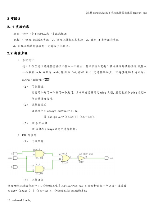
2.2 实验步骤1.系统设计设计1位2选1选通器需要三个输入一个输出,其中中输入需要1根地址线两根数据线.设输入一位数据a,b,地址为addr,输出为Out,根据2to1选通器的特点,可得其逻辑表达式为:_______out=a·addr+b·addr(1)门级描述需要两个与门一个非门一个或门,其中所有变量均为wire类型,且需要三个wire类型中间变量储存信号.(2)逻辑表达式源代码中用assign out=sel?a:b;或 assign out=(a&sel)|(b&~sel);(3)If条件语句If语句在always语句中进行判断。
2.RTL原理图(1)门级结构(2)逻辑语句使用两种逻辑语句进行RTL分析结果略有不同,out=sel?a:b;会分析出来一个2选1选通器而out=(a&sel)|(b&~sel);分析结果与门级结构类似1)out=sel?a:b;2)out=(a&sel)|(b&~sel);(3)if语句3.重要源代码及注释(1)门级结构module mux2_1(a,b,out,addr);input a,b,addr;output out;wire naddr,a1,b1;//定义中间变量not (naddr,addr);and (b1,b,naddr);and (a1,a,addr);or (out,a1,b1);endmodule(2)逻辑语句module luoji(input a,input b,input sel,output out);assign out=(a&sel)|(b&~sel);endmodule(3)if语句module mux2_1if(a,b,sel,out);input a,b,sel;output out;reg out;always@(a or b or sel)beginif(sel) out=a;else out=b;end2。
verilog文档
verilog文档.txt如果青春的时光在闲散中度过,那么回忆岁月将是一场凄凉的悲剧。
杂草多的地方庄稼少,空话多的地方智慧少。
即使路上没有花朵,我仍可以欣赏荒芜。
//-----------------------------------------------------------------------------------// 逻辑运算1// filename: gate4.v//-----------------------------------------------------------------------------------module gate4( IN0 ,IN1 ,OUT0 ,OUT1,OUT2,OUT3 );input IN0 ,IN1 ;output OUT0 ,OUT1,OUT2,OUT3;assign OUT0 = IN0&IN1; //信号赋值语句(assign)assign OUT1 = IN0|IN1; //逻辑运算符(&,|,~,^,)assign OUT2 = ~IN0; //阻赛赋值 (=)assign OUT3 = IN0^IN1; //两目运算符endmodule//-----------------------------------------------------------------------------------// 三态门2 (双向端口三态总线电路的设计)// filename: tri_2.v//-----------------------------------------------------------------------------------module tri_2( outp ,ina ,en );input ina ,en ;output outp ;assign outp= en?in:b'z; //三目运算符相当于如果(en==1)为真则outp=in,//否则outp=zendmodule//-----------------------------------------------------------------------------------// 比较器3// filename: compare.v//-----------------------------------------------------------------------------------module compare( a ,b ,c );input a ,b ;output c ;assign c=(a==b)?a:b; //相当于如果(a==b)条件为真,c=a,否则c=b。
Verilog实例代码

【例3.1】4位全加器module adder4(cout,sum,ina,inb,cin);output[3:0] sum;output cout;input[3:0] ina,inb;input cin;assign {cout,sum}=ina+inb+cin;endmodule【例3.2】4位计数器module count4(out,reset,clk);output[3:0] out;input reset,clk;reg[3:0] out;always @(posedge clk)beginif (reset) out<=0; //同步复位else out<=out+1; //计数endendmodule【例3.3】4位全加器的仿真程序`timescale 1ns/1ns`include "adder4.v"module adder_tp; //测试模块的名字reg[3:0] a,b; //测试输入信号定义为reg型reg cin;wire[3:0] sum; //测试输出信号定义为wire型wire cout;integer i,j;adder4 adder(sum,cout,a,b,cin); //调用测试对象always #5 cin=~cin; //设定cin的取值initialbegina=0;b=0;cin=0;for(i=1;i<16;i=i+1)#10 a=i; //设定a的取值endinitialbeginfor(j=1;j<16;j=j+1)#10 b=j; //设定b的取值endinitial//定义结果显示格式begin$monitor($time,,,"%d + %d + %b={%b,%d}",a,b,cin,cout,sum);#160 $finish;endendmodule【例3.4】4位计数器的仿真程序`timescale 1ns/1ns`include "count4.v"module coun4_tp;reg clk,reset; //测试输入信号定义为reg型wire[3:0] out; //测试输出信号定义为wire型parameter DELY=100;count4 mycount(out,reset,clk); //调用测试对象always #(DELY/2) clk = ~clk; //产生时钟波形initialbegin//激励信号定义clk =0; reset=0;#DELY reset=1;#DELY reset=0;#(DELY*20) $finish;end//定义结果显示格式initial $monitor($time,,,"clk=%d reset=%d out=%d", clk, reset,out); endmodule【例3.5】“与-或-非”门电路module AOI(A,B,C,D,F); //模块名为AOI(端口列表A,B,C,D,F) input A,B,C,D; //模块的输入端口为A,B,C,Doutput F; //模块的输出端口为Fwire A,B,C,D,F; //定义信号的数据类型assign F= ~((A&B)|(C&D)); //逻辑功能描述endmodule【例5.1】用case语句描述的4选1数据选择器module mux4_1(out,in0,in1,in2,in3,sel);output out;input in0,in1,in2,in3;input[1:0] sel;reg out;always @(in0 or in1 or in2 or in3 or sel) //敏感信号列表case(sel)2'b00: out=in0;2'b01: out=in1;2'b10: out=in2;2'b11: out=in3;default: out=2'bx;endcaseendmodule【例5.2】同步置数、同步清零的计数器module count(out,data,load,reset,clk);output[7:0] out;input[7:0] data;input load,clk,reset;reg[7:0] out;always @(posedge clk) //clk上升沿触发beginif (!reset) out = 8'h00; //同步清0,低电平有效else if (load) out = data; //同步预置else out = out + 1; //计数endendmodule【例5.3】用always过程语句描述的简单算术逻辑单元`define add 3'd0`define minus 3'd1`define band 3'd2`define bor 3'd3`define bnot 3'd4module alu(out,opcode,a,b);output[7:0] out;reg[7:0] out;input[2:0] opcode; //操作码input[7:0] a,b; //操作数always@(opcode or a or b) //电平敏感的always块begincase(opcode)`add: out = a+b; //加操作`minus: out = a-b; //减操作`band: out = a&b; //求与`bor: out = a|b; //求或`bnot: out=~a; //求反default: out=8'hx; //未收到指令时,输出任意态endcaseendendmodule【例5.4】用initial过程语句对测试变量A、B、C赋值`timescale 1ns/1nsmodule test;reg A,B,C;initialbeginA = 0;B = 1;C = 0;#50 A = 1; B = 0;#50 A = 0; C = 1;#50 B = 1;#50 B = 0; C = 0;#50 $finish ;endendmodule【例5.5】用begin-end串行块产生信号波形`timescale 10ns/1nsmodule wave1;reg wave;parameter cycle=10;initialbeginwave=0;#(cycle/2) wave=1;#(cycle/2) wave=0;#(cycle/2) wave=1;#(cycle/2) wave=0;#(cycle/2) wave=1;#(cycle/2) $finish ;endinitial $monitor($time,,,"wave=%b",wave); endmodule【例5.6】用fork-join并行块产生信号波形`timescale 10ns/1nsmodule wave2;reg wave;parameter cycle=5;initialforkwave=0;#(cycle) wave=1;#(2*cycle) wave=0;#(3*cycle) wave=1;#(4*cycle) wave=0;#(5*cycle) wave=1;#(6*cycle) $finish;joininitial $monitor($time,,,"wave=%b",wave); endmodule【例5.7】持续赋值方式定义的2选1多路选择器module MUX21_1(out,a,b,sel);input a,b,sel;output out;assign out=(sel==0)?a:b;//持续赋值,如果sel为0,则out=a ;否则out=b endmodule【例5.8】阻塞赋值方式定义的2选1多路选择器module MUX21_2(out,a,b,sel);input a,b,sel;output out;reg out;always@(a or b or sel)beginif(sel==0) out=a; //阻塞赋值else out=b;endendmodule【例5.9】非阻塞赋值module non_block(c,b,a,clk);output c,b;input clk,a;reg c,b;always @(posedge clk)beginb<=a;c<=b;endendmodule【例5.10】阻塞赋值module block(c,b,a,clk);output c,b;input clk,a;reg c,b;always @(posedge clk)beginb=a;c=b;endendmodule【例5.11】模为60的BCD码加法计数器module count60(qout,cout,data,load,cin,reset,clk);output[7:0] qout;output cout;input[7:0] data;input load,cin,clk,reset;reg[7:0] qout;always @(posedge clk) //clk上升沿时刻计数if (reset) qout<=0; //同步复位else if(load) qout<=data; //同步置数else if(cin)beginif(qout[3:0]==9) //低位是否为9,是则beginqout[3:0]<=0; //回0,并判断高位是否为5if (qout[7:4]==5) qout[7:4]<=0;elseqout[7:4]<=qout[7:4]+1; //高位不为5,则加1endelse//低位不为9,则加1qout[3:0]<=qout[3:0]+1;endendassign cout=((qout==8'h59)&cin)?1:0; //产生进位输出信号endmodule【例5.12】BCD码—七段数码管显示译码器module decode4_7(decodeout,indec);output[6:0] decodeout;input[3:0] indec;reg[6:0] decodeout;alwaysbegincase(indec) //用case语句进行译码4'd0:decodeout=7'b1111110;4'd1:decodeout=7'b0110000;4'd2:decodeout=7'b1101101;4'd3:decodeout=7'b1111001;4'd4:decodeout=7'b0110011;4'd5:decodeout=7'b1011011;4'd6:decodeout=7'b1011111;4'd7:decodeout=7'b1110000;4'd8:decodeout=7'b1111111;4'd9:decodeout=7'b1111011;default: decodeout=7'bx;endcaseend【例5.13】用casez描述的数据选择器module mux_casez(out,a,b,c,d,select); output out;input a,b,c,d;input[3:0] select;reg out;always @(select or a or b or c or d) begincasez(select)4'b???1: out = a;4'b??1?: out = b;4'b?1??: out = c;4'b1???: out = d;endcaseendendmodule【例5.14】隐含锁存器举例module buried_ff(c,b,a);output c;input b,a;reg c;always @(a or b)beginif((b==1)&&(a==1)) c=a&b;endendmodule【例5.15】用for语句描述的七人投票表决器module voter7(pass,vote);output pass;input[6:0] vote;reg[2:0] sum;integer i;reg pass;always @(vote)beginsum=0;for(i=0;i<=6;i=i+1) //for语句if(vote[i]) sum=sum+1;if(sum[2]) pass=1; //若超过4人赞成,则pass=1else pass=0;endendmodule【例5.16】用for语句实现2个8位数相乘module mult_for(outcome,a,b);parameter size=8;input[size:1] a,b; //两个操作数output[2*size:1] outcome; //结果reg[2*size:1] outcome;integer i;always @(a or b)beginoutcome=0;for(i=1; i<=size; i=i+1) //for语句if(b[i]) outcome=outcome +(a << (i-1));endendmodule【例5.17】用repeat实现8位二进制数的乘法module mult_repeat(outcome,a,b);parameter size=8;input[size:1] a,b;output[2*size:1] outcome;reg[2*size:1] temp_a,outcome;reg[size:1] temp_b;always @(a or b)beginoutcome=0;temp_a=a;temp_b=b;repeat(size) //repeat语句,size为循环次数beginif(temp_b[1]) //如果temp_b的最低位为1,就执行下面的加法outcome=outcome+temp_a;temp_a=temp_a<<1; //操作数a左移一位temp_b=temp_b>>1; //操作数b右移一位endendendmodule【例5.18】同一循环的不同实现方式module loop1; //方式1integer i;initialfor(i=0;i<4;i=i+1) //for语句begin$display(“i=%h”,i);endendmodulemodule loop2; //方式2integer i;initial begini=0;while(i<4) //while语句begin$display ("i=%h",i);i=i+1;endendendmodulemodule loop3; //方式3integer i;initial begini=0;repeat(4) //repeat语句begin$display ("i=%h",i);i=i+1;endendendmodule【例5.19】使用了`include语句的16位加法器`include "adder.v"module adder16(cout,sum,a,b,cin);output cout;parameter my_size=16;output[my_size-1:0] sum;input[my_size-1:0] a,b;input cin;adder my_adder(cout,sum,a,b,cin); //调用adder模块endmodule//下面是adder模块代码module adder(cout,sum,a,b,cin);parameter size=16;output cout;output[size-1:0] sum;input cin;input[size-1:0] a,b;assign {cout,sum}=a+b+cin;endmodule【例5.20】条件编译举例module compile(out,A,B);output out;input A,B;`ifdef add //宏名为add assign out=A+B;`elseassign out=A-B;`endifendmodule【例6.1】加法计数器中的进程module count(data,clk,reset,load,cout,qout);output cout;output[3:0] qout;reg[3:0] qout;input[3:0] data;input clk,reset,load;always @(posedge clk) //进程1,always过程块beginif (!reset) qout= 4'h00; //同步清0,低电平有效else if (load) qout= data; //同步预置else qout=qout + 1; //加法计数endassign cout=(qout==4'hf)?1:0; //进程2,用持续赋值产生进位信号endmodule【例6.2】任务举例module alutask(code,a,b,c);input[1:0] code;input[3:0] a,b;output[4:0] c;reg[4:0] c;task//任务定义,注意无端口列表input//a,b,out名称的作用域范围为task任务内部output[4:0] out;integer i;beginfor(i=3;i>=0;i=i-1)out[i]=a[i]&b[i]; //按位与endendtaskalways@(code or a or b)begincase(code)2'b00: my_and(a,b,c);/* 调用任务my_and,需注意端口列表的顺序应与任务定义中的一致,这里的a,b,c 分别对应任务定义中的a,b,out */2'b01: c=a|b; //或2'b10: c=a-b; //相减2'b11: c=a+b; //相加endcaseendendmodule【例6.3】测试程序`include "alutask.v"module alu_tp;reg[3:0] a,b;reg[1:0] code;wire[4:0] c;parameter DELY = 100;alutask ADD(code,a,b,c); //调用被测试模块initial begincode=4'd0; a= 4'b0000; b= 4'b1111;#DELY code=4'd0; a= 4'b0111; b= 4'b1101;#DELY code=4'd1; a= 4'b0001; b= 4'b0011;#DELY code=4'd2; a= 4'b1001; b= 4'b0011;#DELY code=4'd3; a= 4'b0011; b= 4'b0001;#DELY code=4'd3; a= 4'b0111; b= 4'b1001;#DELY $finish;endinitial $monitor($time,,,"code=%b a=%b b=%b c=%b", code,a,b,c); endmodule【例6.4】函数function[7:0] get0;input[7:0] x;reg[7:0] count;integer i;begincount=0;for (i=0;i<=7;i=i+1)if (x[i]=1'b0) count=count+1;get0=count;endendfunction【例6.5】用函数和case语句描述的编码器(不含优先顺序)module code_83(din,dout);input[7:0] din;output[2:0] dout;function[2:0] code; //函数定义input[7:0] din; //函数只有输入,输出为函数名本身casex (din)8'b1xxx_xxxx : code = 3'h7;8'b01xx_xxxx : code = 3'h6;8'b001x_xxxx : code = 3'h5;8'b0001_xxxx : code = 3'h4;8'b0000_1xxx : code = 3'h3;8'b0000_01xx : code = 3'h2;8'b0000_001x : code = 3'h1;8'b0000_000x : code = 3'h0;default: code = 3'hx;endcaseendfunctionassign dout = code(din) ; //函数调用endmodule【例6.6】阶乘运算函数module funct(clk,n,result,reset);output[31:0] result;input[3:0] n;input reset,clk;reg[31:0] result;always @(posedge clk) //在clk的上升沿时执行运算beginif(!reset) result<=0; //复位else beginresult <= 2 * factorial(n); //调用factorial函数endendfunction[31:0] factorial; //阶乘运算函数定义(注意无端口列表)input[3:0] opa; //函数只能定义输入端,输出端口为函数名本身reg[3:0] i;beginfactorial = opa ? 1 : 0;for(i= 2; i <= opa; i = i+1) //该句若要综合通过,opa应赋具体的数值factorial = i* factorial; //阶乘运算endfunctionendmodule【例6.7】测试程序`define clk_cycle 50`include "funct.v"module funct_tp;reg[3:0] n;reg reset,clk;wire[31:0] result;initial//定义激励向量beginn=0; reset=1; clk=0;for(n=0;n<=15;n=n+1)#100 n=n;endinitial $monitor($time,,,"n=%d result=%d",n,result);//定义输出显示格式always # `clk_cycle clk=~clk; //产生时钟信号funct funct_try(.clk(clk),.n(n),.result(result),.reset(reset));//调用被测试模块endmodule【例6.8】顺序执行模块1module serial1(q,a,clk);output q,a;input clk;reg q,a;always @(posedge clk)beginq=~q;a=~q;endendmodule【例6.9】顺序执行模块2module serial2(q,a,clk);input clk;reg q,a;always @(posedge clk)begina=~q;q=~q;endendmodule【例6.10】并行执行模块1 module paral1(q,a,clk); output q,a;input clk;reg q,a;always @(posedge clk)beginq=~q;endalways @(posedge clk)begina=~q;endendmodule【例6.11】并行执行模块2 module paral2(q,a,clk); output q,a;input clk;reg q,a;always @(posedge clk)begina=~q;endalways @(posedge clk)beginq=~q;endendmodulemodule mux4_1a(out,in1,in2,in3,in4,cntrl1,cntrl2); output out;input in1,in2,in3,in4,cntrl1,cntrl2;wire notcntrl1,notcntrl2,w,x,y,z;not(notcntrl1,cntrl2),(notcntrl2,cntrl2);and (w,in1,notcntrl1,notcntrl2),(x,in2,notcntrl1,cntrl2),(y,in3,cntrl1,notcntrl2),(z,in4,cntrl1,cntrl2);or (out,w,x,y,z);endmodule【例7.2】用case语句描述的4选1 MUXmodule mux4_1b(out,in1,in2,in3,in4,cntrl1,cntrl2); output out;input in1,in2,in3,in4,cntrl1,cntrl2;reg out;always@(in1 or in2 or in3 or in4 or cntrl1 or cntrl2) case({cntrl1,cntrl2})2'b00:out=in1;2'b01:out=in2;2'b10:out=in3;2'b11:out=in4;default:out=2'bx;endcaseendmodule【例7.3】行为描述方式实现的4位计数器module count4(clk,clr,out);input clk,clr;output[3:0] out;reg[3:0] out;always @(posedge clk or posedge clr)beginif (clr) out<=0;else out<=out+1;endendmodule【例7.4】数据流方式描述的4选1 MUXmodule mux4_1c(out,in1,in2,in3,in4,cntrl1,cntrl2);output out;input in1,in2,in3,in4,cntrl1,cntrl2;assign out=(in1 & ~cntrl1 & ~cntrl2)|(in2 & ~cntrl1 & cntrl2)| (in3 & cntrl1 & ~cntrl2)|(in4 & cntrl1 & cntrl2); endmodule【例7.5】用条件运算符描述的4选1 MUXmodule mux4_1d(out,in1,in2,in3,in4,cntrl1,cntrl2);output out;input in1,in2,in3,in4,cntrl1,cntrl2;assign out=cntrl1 ? (cntrl2 ? in4:in3):(cntrl2 ? in2:in1); endmodule【例7.6】门级结构描述的2选1MUXmodule mux2_1a(out,a,b,sel);output out;input a,b,sel;not (sel_,sel);and(a1,a,sel_),(a2,b,sel);or (out,a1,a2);endmodule【例7.7】行为描述的2选1MUXmodule mux2_1b(out,a,b,sel);output out;input a,b,sel;reg out;always @(a or b or sel)beginif(sel) out = b;else out = a;endendmodule【例7.8】数据流描述的2选1MUXmodule MUX2_1c(out,a,b,sel);input a,b,sel;assign out = sel ? b : a;endmodule【例7.9】调用门元件实现的1位半加器module half_add1(a,b,sum,cout);input a,b;output sum,cout;and(cout,a,b);xor(sum,a,b);endmodule【例7.10】数据流方式描述的1位半加器module half_add2(a,b,sum,cout);input a,b;output sum,cout;assign sum=a^b;assign cout=a&b;endmodule【例7.11】采用行为描述的1位半加器module half_add3(a,b,sum,cout);input a,b;output sum,cout;reg sum,cout;always @(a or b)begincase ({a,b}) //真值表描述2'b00: begin sum=0; cout=0; end2'b01: begin sum=1; cout=0; end2'b10: begin sum=1; cout=0; end2'b11: begin sum=0; cout=1; endendcaseendendmodule【例7.12】采用行为描述的1位半加器module half_add4(a,b,sum,cout);input a,b;reg sum,cout;always @(a or b)beginsum= a^b;cout=a&b;endendmodule【例7.13】调用门元件实现的1位全加器module full_add1(a,b,cin,sum,cout);input a,b,cin;output sum,cout;wire s1,m1,m2,m3;and (m1,a,b),(m2,b,cin),(m3,a,cin);xor(s1,a,b),(sum,s1,cin);or(cout,m1,m2,m3);endmodule【例7.14】数据流描述的1位全加器module full_add2(a,b,cin,sum,cout);input a,b,cin;output sum,cout;assign sum = a ^ b ^ cin;assign cout = (a & b)|(b & cin)|(cin & a); endmodule【例7.15】1位全加器module full_add3(a,b,cin,sum,cout);input a,b,cin;output sum,cout;assign {cout,sum}=a+b+cin;endmodule【例7.16】行为描述的1位全加器module full_add4(a,b,cin,sum,cout);input a,b,cin;reg sum,cout; //在always块中被赋值的变量应定义为reg型reg m1,m2,m3;always @(a or b or cin)beginsum = (a ^ b) ^ cin;m1 = a & b;m2 = b & cin;m3 = a & cin;cout = (m1|m2)|m3;endendmodule【例7.17】混合描述的1位全加器 module full_add5(a,b,cin,sum,cout);input a,b,cin;output sum,cout;reg cout,m1,m2,m3; //在always块中被赋值的变量应定义为reg型wire s1;xor x1(s1,a,b); //调用门元件always @(a or b or cin) //always块语句beginm1 = a & b;m2 = b & cin;m3 = a & cin;cout = (m1| m2) | m3;endassign sum = s1 ^ cin; //assign持续赋值语句endmodule【例7.18】结构描述的4位级连全加器 `include "full_add1.v"module add4_1(sum,cout,a,b,cin);output[3:0] sum;output cout;input[3:0] a,b;input cin;full_add1 f0(a[0],b[0],cin,sum[0],cin1); //级连描述full_add1 f1(a[1],b[1],cin1,sum[1],cin2);full_add1 f2(a[2],b[2],cin2,sum[2],cin3);- 21 -full_add1 f3(a[3],b[3],cin3,sum[3],cout);endmodule【例7.19】数据流描述的4位全加器module add4_2(cout,sum,a,b,cin);output[3:0] sum;output cout;input[3:0] a,b;input cin;assign {cout,sum}=a+b+cin;endmodule【例7.20】行为描述的4位全加器module add4_3(cout,sum,a,b,cin);output[3:0] sum;output cout;input[3:0] a,b;input cin;reg[3:0] sum;reg cout;always @(a or b or cin)begin{cout,sum}=a+b+cin;endendmodule【例8.1】$time与$realtime的区别`timescale 10ns/1nsmodule time_dif;reg ts;parameter delay=2.6;initialbegin#delay ts=1;#delay ts=0;#delay ts=1;#delay ts=0;endinitial $monitor($time,,,"ts=%b",ts); //使用函数$time - 22 -endmodule【例8.2】$random函数的使用`timescale 10ns/1nsmodule random_tp;integer data;integer i;parameter delay=10;initial $monitor($time,,,"data=%b",data);initial beginfor(i=0; i<=100; i=i+1)#delay data=$random; //每次产生一个随机数endendmodule【例8.3】1位全加器进位输出UDP元件primitive carry_udp(cout,cin,a,b);input cin,a,b;output cout;table//cin a b : cout //真值表0 0 0 : 0;0 1 0 : 0;0 0 1 : 0;0 1 1 : 1;1 0 0 : 0;1 0 1 : 1;1 1 0 : 1;1 1 1 : 1;endtableendprimitive【例8.4】包含x态输入的1位全加器进位输出UDP元件primitive carry_udpx1(cout,cin,a,b);input cin,a,b;output cout;table// cin a b : cout //真值表0 0 0 : 0;- 23 -0 1 0 : 0;0 0 1 : 0;0 1 1 : 1;1 0 0 : 0;1 0 1 : 1;1 1 0 : 1;1 1 1 : 1;0 0 x : 0; //只要有两个输入为0,则进位输出肯定为00 x 0 : 0;x 0 0 : 0;1 1 x : 1; //只要有两个输入为1,则进位输出肯定为11 x 1 : 1;x 1 1 : 1;endtableendprimitive【例8.5】用简缩符“?”表述的1位全加器进位输出UDP元件primitive carry_udpx2(cout,cin,a,b);input cin,a,b;output cout;table// cin a b : cout //真值表? 0 0 : 0; //只要有两个输入为0,则进位输出肯定为00 ? 0 : 0;0 0 ? : 0;? 1 1 : 1; //只要有两个输入为1,则进位输出肯定为11 ? 1 : 1;1 1 ? : 1;endtableendprimitive【例8.6】3选1多路选择器UDP元件primitive mux31(Y,in0,in1,in2,s2,s1);input in0,in1,in2,s2,s1;output Y;table//in0 in1 in2 s2 s1 : Y0 ? ? 0 0 : 0; //当s2s1=00时,Y=in01 ? ? 0 0 : 1;? 0 ? 0 1 : 0; //当s2s1=01时,Y=in1- 24 -? 1 ? 0 1 : 1;? ? 0 1 ? : 0; //当s2s1=1?时,Y=in2? ? 1 1 ? : 1;0 0 ? 0 ? : 0;1 1 ? 0 ? : 1;0 ? 0 ? 0 : 0;1 ? 1 ? 0 : 1;? 0 0 ? 1 : 0;? 1 1 ? 1 : 1;endtableendprimitive【例8.7】电平敏感的1位数据锁存器UDP元件primitive latch(Q,clk,reset,D);input clk,reset,D;output Q;reg Q;initial Q = 1'b1; //初始化table// clk reset D : state : Q? 1 ? : ? : 0 ; //reset=1,则不管其他端口为什么值,输出都为00 0 0 : ? : 0 ; //clk=0,锁存器把D端的输入值输出0 0 1 : ? : 1 ;1 0 ? : ? : - ; //clk=1,锁存器的输出保持原值,用符号“-”表示endtableendprimitive【例8.8】上升沿触发的D触发器UDP元件primitive DFF(Q,D,clk);output Q;input D,clk;reg Q;table//clk D : state : Q(01) 0 : ? : 0; //上升沿到来,输出Q=D(01) 1 : ? : 1;(0x) 1 : 1 : 1;(0x) 0 : 0 : 0;(?0) ? : ? : -; //没有上升沿到来,输出Q保持原值? (??) : ? : - ; //时钟不变,输出也不变- 25 -endprimitive【例8.9】带异步置1和异步清零的上升沿触发的D触发器UDP元件primitive DFF_UDP(Q,D,clk,clr,set);output Q;input D,clk,clr,set;reg Q;table// clk D clr s et : state : Q(01) 1 0 0 : ? : 0;(01) 1 0 x : ? : 0;? ? 0 x : 0 : 0;(01) 0 0 0 : ? : 1;(01) 0 x 0 : ? : 1;? ? x 0 : 1 : 1;(x1) 1 0 0 : 0 : 0;(x1) 0 0 0 : 1 : 1;(0x) 1 0 0 : 0 : 0;(0x) 0 0 0 : 1 : 1;? ? 1 ? : ? : 1; //异步复位? ? 0 1 : ? : 0; //异步置1n ? 0 0 : ? : -;? * ? ? : ? : -;? ? (?0) ? : ? : -;? ? ? (?0): ? : -;? ? ? ? : ? : x;endtableendprimitive【例8.12】延迟定义块举例module delay(out,a,b,c);output out;input a,b,c;and a1(n1,a,b);or o1(out,c,n1);specify(a=>out)=2;(b=>out)=3;(c=>out)=1;- 26 -endmodule【例8.13】激励波形的描述'timescale 1ns/1nsmodule test1;reg A,B,C;initialbegin//激励波形描述A = 0;B = 1;C = 0;#100 C = 1;#100 A = 1; B = 0;#100 A = 0;#100 C = 0;#100 $finish;endinitial $monitor($time,,,"A=%d B=%d C=%d",A,B,C); //显示endmodule【例8.15】用always过程块产生两个时钟信号module test2;reg clk1,clk2;parameter CYCLE = 100;alwaysbegin{clk1,clk2} = 2'b10;#(CYCLE/4) {clk1,clk2} = 2'b01;#(CYCLE/4) {clk1,clk2} = 2'b11;#(CYCLE/4) {clk1,clk2} = 2'b00;#(CYCLE/4) {clk1,clk2} = 2'b10;endinitial $monitor($time,,,"clk1=%b clk2=%b",clk1,clk2);endmodule【例8.17】存储器在仿真程序中的应用module ROM(addr,data,oe);output[7:0] data; //数据信号input[14:0] addr; //地址信号input oe; //读使能信号,低电平有效- 27 -reg[7:0] mem[0:255]; //存储器定义parameter DELAY = 100;assign #DELAY data=(oe==0) ? mem[addr] : 8'hzz;initial $readmemh("rom.hex",mem); //从文件中读入数据endmodule【例8.18】8位乘法器的仿真程序`timescale 10ns/1nsmodule mult_tp; //测试模块的名字reg[7:0] a,b; //测试输入信号定义为reg型wire [15:0] out; //测试输出信号定义为wire型integer i,j;mult8 m1(out,a,b); //调用测试对象//激励波形设定initialbegina=0;b=0;for(i=1;i<255;i=i+1)#10 a=i;endinitialbeginfor(j=1;j<255;j=j+1)#10 b=j;endinitial//定义结果显示格式begin$monitor($time,,,"%d * %d= %d",a,b,out);#2560 $finish;endendmodulemodule mult8(out, a, b); //8位乘法器源代码parameter size=8;input[size:1] a,b; //两个操作数output[2*size:1] out; //结果assign out=a*b; //乘法运算符- 28 -endmodule【例8.19】8位加法器的仿真程序`timescale 1ns/1nsmodule add8_tp; //仿真模块无端口列表reg[7:0] A,B; //输入激励信号定义为reg型reg cin;wire[7:0] SUM; //输出信号定义为wire型wire cout;parameter DELY = 100;add8 AD1(SUM,cout,A,B,cin); //调用测试对象initial begin//激励波形设定A= 8'd0; B= 8'd0; cin=1'b0;#DELY A= 8'd100; B= 8'd200; cin=1'b1;#DELY A= 8'd200; B= 8'd88;#DELY A= 8'd210; B= 8'd18; cin=1'b0;#DELY A= 8'd12; B= 8'd12;#DELY A= 8'd100; B= 8'd154;#DELY A= 8'd255; B= 8'd255; cin=1'b1;#DELY $finish;end//输出格式定义initial $monitor($time,,,"%d + %d + %b = {%b, %d}",A,B,cin,cout,SUM); endmodulemodule add8(SUM,cout,A,B,cin); //待测试的8位加法器模块output[7:0] SUM;output cout;input[7:0] A,B;input cin;assign {cout,SUM}=A+B+cin;endmodule【例8.20】2选1多路选择器的仿真`timescale 1ns/1nsmodule mux_tp;reg a,b,sel;wire out;- 29 -MUX2_1 m1(out,a,b,sel); //调用待测试模块initialbegina=1'b0; b=1'b0; sel=1'b0;#5 sel=1'b1;#5 a=1'b1; s el=1'b0;#5 sel=1'b1;#5 a=1'b0; b=1'b1; sel=1'b0;#5 sel=1'b1;#5 a=1'b1; b=1'b1; sel=1'b0;#5 sel=1'b1;endinitial $monitor($time,,,"a=%b b=%b sel=%b out=%b",a,b,sel,out);endmodulemodule MUX2_1(out,a,b,sel); //待测试的2选1MUX模块input a,b,sel;output out;not #(0.4,0.3) (sel_,sel); //#(0.4,0.3)为门延时and #(0.7,0.6) (a1,a,sel_);and #(0.7,0.6) (a2,b,sel);or #(0.7,0.6) (out,a1,a2);endmodule【例8.21】8位计数器的仿真`timescale 10ns/1nsmodule count8_tp;reg clk,reset; //输入激励信号定义为reg型wire[7:0] qout; //输出信号定义为wire型parameter DELY=100;counter C1(qout,reset,clk); //调用测试对象always #(DELY/2) clk = ~clk; //产生时钟波形initialbegin//激励波形定义clk =0; reset=0;- 30 -#DELY reset=1;#DELY reset=0;#(DELY*300) $finish;end//结果显示initial $monitor($time,,,"clk=%d reset=%d qout=%d",clk,reset,qout); endmodulemodule counter(qout,reset,clk); //待测试的8位计数器模块output[7:0] qout;input clk,reset;reg[7:0] qout;always @(posedge clk)begin if (reset) qout<=0;else qout<=qout+1;endendmodule【例9.1】基本门电路的几种描述方法(1)门级结构描述module gate1(F,A,B,C,D);input A,B,C,D;output F;nand(F1,A,B); //调用门元件and(F2,B,C,D);or(F,F1,F2);endmodule(2)数据流描述module gate2(F,A,B,C,D);input A,B,C,D;output F;assign F=(A&B)|(B&C&D); //assign持续赋值endmodule(3)行为描述module gate3(F,A,B,C,D);input A,B,C,D;output F;- 31 -reg F;always @(A or B or C or D) //过程赋值beginF=(A&B)|(B&C&D);endendmodule【例9.2】用bufif1关键字描述的三态门module tri_1(in,en,out);input in,en;output out;tri out;bufif1 b1(out,in,en); //注意三态门端口的排列顺序endmodule【例9.3】用assign语句描述的三态门module tri_2(out,in,en);output out;input in,en;assign out = en ? in : 'bz;//若en=1,则out=in;若en=0,则out为高阻态endmodule【例9.4】三态双向驱动器module bidir(tri_inout,out,in,en,b);inout tri_inout;output out;input in,en,b;assign tri_inout = en ? in : 'bz;assign out = tri_inout ^ b;endmodule【例9.5】三态双向驱动器module bidir2(bidir,en,clk);inout[7:0] bidir;input en,clk;reg[7:0] temp;assign bidir= en ? temp : 8'bz;always @(posedge clk)begin- 32 -if(en) temp=bidir;else temp=temp+1;endendmodule【例9.6】3-8译码器module decoder_38(out,in);output[7:0] out;input[2:0] in;reg[7:0] out;always @(in)begincase(in)3'd0: out=8'b11111110;3'd1: out=8'b11111101;3'd2: out=8'b11111011;3'd3: out=8'b11110111;3'd4: out=8'b11101111;3'd5: out=8'b11011111;3'd6: out=8'b10111111;3'd7: out=8'b01111111;endcaseendendmodule【例9.7】8-3优先编码器module encoder8_3(none_on,outcode,a,b,c,d,e,f,g,h);output none_on;output[2:0] outcode;input a,b,c,d,e,f,g,h;reg[3:0] outtemp;assign {none_on,outcode}=outtemp;always @(a or b or c or d or e or f or g or h)beginif(h) outtemp=4'b0111;else if(g) outtemp=4'b0110;else if(f) outtemp=4'b0101;else if(e) outtemp=4'b0100;else if(d) outtemp=4'b0011;else if(c) outtemp=4'b0010;- 33 -else if(b) outtemp=4'b0001;else if(a) outtemp=4'b0000;else outtemp=4'b1000;endendmodule【例9.8】用函数定义的8-3优先编码器module code_83(din, dout);input[7:0] din;output[2:0] dout;function[2:0] code; //函数定义input[7:0] din; //函数只有输入端口,输出为函数名本身if (din[7]) code = 3'd7;else if (din[6]) code = 3'd6;else if (din[5]) code = 3'd5;else if (din[4]) code = 3'd4;else if (din[3]) code = 3'd3;else if (din[2]) code = 3'd2;else if (din[1]) code = 3'd1;else code = 3'd0;endfunctionassign dout = code(din); //函数调用endmodule【例9.9】七段数码管译码器module decode47(a,b,c,d,e,f,g,D3,D2,D1,D0);output a,b,c,d,e,f,g;input D3,D2,D1,D0; //输入的4位BCD码reg a,b,c,d,e,f,g;always @(D3 or D2 or D1 or D0)begincase({D3,D2,D1,D0}) //用case语句进行译码4'd0: {a,b,c,d,e,f,g}=7'b1111110;4'd1: {a,b,c,d,e,f,g}=7'b0110000;4'd2: {a,b,c,d,e,f,g}=7'b1101101;4'd3: {a,b,c,d,e,f,g}=7'b1111001;4'd4: {a,b,c,d,e,f,g}=7'b0110011;4'd5: {a,b,c,d,e,f,g}=7'b1011011;- 34 -4'd6: {a,b,c,d,e,f,g}=7'b1011111;4'd7: {a,b,c,d,e,f,g}=7'b1110000;4'd8: {a,b,c,d,e,f,g}=7'b1111111;4'd9: {a,b,c,d,e,f,g}=7'b1111011;default: {a,b,c,d,e,f,g}=7'bx;endcaseendendmodule【例9.10】奇偶校验位产生器module parity(even_bit,odd_bit,input_bus);output even_bit,odd_bit;input[7:0] input_bus;assign odd_bit = ^ input_bus; //产生奇校验位assign even_bit = ~odd_bit; //产生偶校验位endmodule【例9.11】用if-else语句描述的4选1 MUXmodule mux_if(out,in0,in1,in2,in3,sel);output out;input in0,in1,in2,in3;input[1:0] sel;reg out;always @(in0 or in1 or in2 or in3 or sel)beginif(sel==2'b00) out=in0;else if(sel==2'b01) out=in1;else if(sel==2'b10) out=in2;else out=in3;endendmodule【例9.12】用case语句描述的4选1 MUXmodule mux_case(out,in0,in1,in2,in3,sel);output out;input in0,in1,in2,in3;input[1:0] sel;reg out;always @(in0 or in1 or in2 or in3 or sel)begin- 35 -。
Verilog逻辑设计实例系列二

***例 1.5 32位的比较器和 位的比较器具有同样的功能,所 例 位的比较器具有同样的功能, 位的比较器和2位的比较器具有同样的功能 以我们可以通过增加一个用来定义数据通道字长大小的参 在上一个例子模型的基础上加以改进。 数,在上一个例子模型的基础上加以改进。这个模型可读 性强、 性强、容易理解还能扩展为任意大小的数据通道比较器的 情形。 情形。 module compare_32_CA (A_gt_B, A_lt_B, A_eq_B, A, B); parameter word_size = 32; input [word_size – 1 : 0] A,B; output A_gt_B, A_lt_B, A_eq_B; assign assign assign endmodule A_lt_B =(A < B); A_gt_B =(A > B); A_eq_B =(A == B);
4位比较器用如图所示的框图符号表示。比较器通过 位比较器用如图所示的框图符号表示。 位断它们的相对大小。 位二进制数, 比较 位二进制数,来判断它们的相对大小。由于输出布 尔方程难以写出,因而可将两个2位比较器的输出和附加 尔方程难以写出,因而可将两个 位比较器的输出和附加 逻辑连接起来,通过比较4位字的大小产生相应的输出 位字的大小产生相应的输出。 逻辑连接起来,通过比较 位字的大小产生相应的输出。 连接2位比较器的逻辑依据的规则是 位比较器的逻辑依据的规则是: 连接 位比较器的逻辑依据的规则是:高位的严格不等即 可决定4位数的相对大小 如果高位相等, 位数的相对大小; 可决定 位数的相对大小;如果高位相等,可逐位比较低 由低位的大小决定输出。 位,由低位的大小决定输出。
assignaltbassignagtbassignaeqbendmodule例1532位的比较器和2位的比较器具有同样的功能所以我们可以通过增加一个用来定义数据通道字长大小的参数在上一个例子模型的基础上加以改进
(完整word版)Verilog电话计费器的代码
Verilog电话计费器的代码/*信号定义:clk:时钟信号,本例中其频率值为1Hz;decide:电话局反馈回来的信号,代表话务种类,“01”表示市话,“10”表示长话,“11"表示特话;dispmoney:用来显示卡内余额,其单位为角,这里假定能显示的最大数额为50元(500角);disptime:显示本次通话的时长;write,read: 当write信号下降沿到来时写卡,当话卡插入,read信号变高时读卡;warn:余额过少时的告警信号。
本例中,当打市话时,余额少于3角,打长话时,余额少于6角,即会产生告警信号;cut:当告警时间过长时自动切断通话信号. */module account(state,clk,card,decide,disptime,dispmoney,write,read,warn,cut);output write,read,warn,cut;input state,clk,card;input[2:1] decide;output[10:0]dispmoney;output[8:0] disptime;reg[10:0] money;reg[8:0]dtime;reg warn,cut,write,t1m; //t1m为分时钟reg set,reset_ena;integer num1,temp;assign dispmoney=card?money:0;assign disptime=dtime;assign read=card?1:0;always @(posedge clk)beginif (num1==59)begin num1<=0;t1m<=1;end else beginif(state) num1〈=num1+1;else num1<=0;t1m<=0;endendalways @(negedge clk) //该进程完成电话计费功能beginif(!set)begin money<=11'h500;set〈=1; endif(card&state)if(t1m)case({state,decide})3’b101:if(money<3)begin warn〈=1;write<=0;reset_ena〈=1;end elsebegin //市话计费if(money[3:0]<4’b0011)beginmoney[3:0]〈=money[3:0]+7;if(money[7:4]!=0)money[7:4]〈=money[7:4]—1;elsebegin money[7:4]<=9;money[10:8]〈=money[10:8]-1;end endelse money[3:0]〈=money[3:0]—3;write〈=1;//市话通话计时if(dtime[3:0]==9)begindtime[3:0]<=0;if(dtime[7:4]==9)begin dtime[7:4]<=0;dtime[8]<=dtime[8]+1; endelse dtime[7:4]<=dtime[7:4]+1;endelsebegindtime[3:0]<=dtime[3:0]+1; warn<=0;reset_ena〈=0;endend3’b110:if(money<6)begin warn〈=1;write<=0;reset_ena〈=1;endelse begin//通话计时if(dtime[3:0]==9)begindtime[3:0]<=0;if(dtime[7:4]==9)begin dtime[7:4]〈=0;dtime[8]〈=dtime[8]+1;endelse dtime[7:4]<=dtime[7:4]+1;endelse dtime[3:0]〈=dtime[3:0]+1;//长话计费if(money[3:0]<4'b0110)beginmoney[3:0]〈=money[3:0]+4;if(!money[7:4])begin money[7:4]〈=9;money[10:8]<=money[10:8]—1;end else money[7:4]〈=money[7:4]—1;endelse money[3:0]<=money[3:0]-6;write〈=1; reset_ena<=0;warn<=0;endendcaseelse write<=0;else begin dtime〈=0;warn<=0; write〈=0; reset_ena<=0; en //取卡后对一些信号进行复位endalways @(posedge clk)//该进程在告警时间过长的情况下切断本次通话beginif(warn) temp〈=temp+1;else temp〈=0;if(temp==15)begin cut<=1; temp〈=0; endif(!card||!reset_ena)begincut〈=0; //复位cut信号temp<=0;endendendmodule。
verilog代码
Testbench编写的三步骤:1、对被测试的设计的丁岑接口进行例化。
2、给被测试的设计的输入输出添加激励。
3、判断被测试的设计的输出响应是否满足设计要求。
简单的Testbench包括:时钟产生、复位产生、其他的激励产生,和对比输出观察;1.最简单的TESTBENCH第一种时钟产生方式://时钟产生//定义时周期是20ns,已定义timescale 1ns /1ps注意这里的1s=10^9ns = 10^12ps Parameter PERIOD = 20;Initial beginClk = 0;Forever //永远执行#(PERIOD/2)clk = ~clk; //每10ns实现时钟的翻转,20ns就是一个时钟周期end第二种时钟产生方式://时钟产生//定义时周期是20ns,已定义timescale 1ns /1ps注意这里的1s=10^9ns = 10^12ps Parameter PERIOD = 20;Always begin //脚本一运行就进入always的无限循环中#(PERIOD/2)clk = 0;#(PERIOD/2)clk = 1;end//简单的复位脚本Initial begin//复位低电平有效,已定义“timescale 1ns / 1ps”Rst_n = 0;#100; //100ns延时Rst_n = 1;// 撤销复位.......End//可重用的复位脚本//复位产生Initial beginReset_task(100); //复位100ns,已定义“timescale 1ns / 1ps”......EndTask reset_task;Input[15:0]reset_time; //复位时间BeginReset = 0;#reset_time;Reset = 1;end//推荐书籍:《设计与验证verilog HDL》吴继华王城。
verilog实例代码2word版本
实or2码代例gliev //与门module zxhand2(c,a,b);input a,b;output c;assign c= a & b;endmodule//或门module zxhor2(c,a,b);input a,b;output c;assign c= a | b;endmodule//非门module zxhnot2(c,b);input b;output c;assign c=~ b;endmodule////异或门module zxhxro2(c,a,b);output c;assign c=a ^ b;endmodule两选一电路module data_scan(d0,d1,sel,q);output q;input d0,d1,sel;wire t1,t2,t3;n1 zxhand2(t1,d0,sel);n2 zxhnot2 (t4,sel);n3 zxhand2(t2,d1,t4);n4 zxhor2(t3,t1,t2);assign q=t1;endmoduleverilog HDL实例(一)练习一.简单的组合逻辑设计目的: 掌握基本组合逻辑电路的实现方法。
这是一个可综合的数据比较器,很容易看出它的功能是比较数据a与数据b,如果两个数据相同,则给出结果1,否则给出结果0。
在Verilog HDL中,描述组合逻辑时常使用assign结构。
注意equal=(a==b)?1:0,这是一种在组合逻辑实现分支判断时常使用的格式。
模块源代码://--------------- compare.v -----------------module compare(equal,a,b);input a,b;output equal;assign equal=(a==b)?1:0; //a等于b时,equal输出为1;a不等于b时,//equal输出为0。
endmodule测试模块用于检测模块设计得正确与否,它给出模块的输入信号,观察模块的内部信号和输出信号,如果发现结果与预期的有所偏差,则要对设计模块进行修改。
(完整word版)数字模块实例-Verilog
一、加、减法器 (2)1、半加器 (2)2、全加器 (2)3、串行进位加法器(行波进位加法器) (4)4、超前进位加法器(先行进位加法器) (4)5、进位链加法器、跳跃进位加法器 (7)6、进位旁路加法器、线性进位选择加法器等 (9)7、减法器 (9)二、乘法器 (10)1、定点原码乘法器 (10)2、加法树乘法器 (12)3、查找表乘法器 (13)4、布尔乘法器 (14)三、CORDIC数字计算机 (18)四、Johnson 计数器 (21)五、移位寄存器 (22)1 、串并转换模块 (22)2 生成伪随机数及伪随机序列应用设计 (24)3 桶形移位寄存器(循环移位寄存器) (27)六、编码译码器 (29)1 、差错控制编码 (29)2、HDB3 编码与译码 (37)3 曼彻斯特编译码器 (39)RS(204,1 88 )译码器 (46)4、Gray 码与二进制码的转换 (46)5、NRZI 编码 (46)七、加密解密模块 (48)1、DES加密模块 (48)亠、加、减法器1、半加器半加器:输入为两个二进制数,输出产生两个二进制数,一个和位、一个进位,不包括S -A f B +AB f来自低位的进位。
逻辑表达式为:(,其电路符号为:;—$LL Q—82、全加器在将两个多位二进制数相加时,除了最低位以外,每一位都应该考虑来自低位的进位,这种运算为全加,其电路为全加器。
逻辑表达式为由半加器组成的结构如下:Cl*} *co ^-Axry\ L—「vz -------------- 7 -------- 亠--------------------- * *F—~ ~1 "> ---------- ---------------------------------- vcVerilog 模型module addl (a^b/Ci^s,co>; f/ data flow style input a,b r ci;output s,co;assign 3 = a ' b " ci;assign co - (a & b) l (b & ci) | (ci & a); endmodule或module fa_behavioral (a, b, ci lf s, co); // behavioral style input a,b f ci;output s,co;assign {co f s J - a + b + ci;endmodule3、串行进位加法器(行波进位加法器)依次将低位全加器的进位输出端 CO 接到高位全加器的进位输入端 C ,就可以构成多位加法器。
i2c_verilog范例
// $Locker: $
// $State: Exp $
//
// Change History:
//
$Log: i2c_master_top.v,v $
//
Revision 1.10 2003/09/01 10:34:38 rherveille
//
Fix a blocking vs. non-blocking error in the wb_dat output mux.
//// OF THE USE OF THIS SOFTWARE, EVEN IF ADVISED OF THE
////
//// POSSIBILITY OF SUCH DAMAGE.
////
////
////
/////////////////////////////////////////////////////////////////////
// status register signals
wire irxack;
reg rxack;
// received aknowledge from slave
reg tip;
// transfer in progress
reg irq_flag; // interrupt pending flag
File: Edit1 9/19/2004, 7:54:04PM
/////////////////////////////////////////////////////////////////////
////
////
//// WISHBONE revB.2 compliant I2C Master controller Top-level ////
VerilogHDL举例2

VerilogHDL举例2任务举例module alutask(code,a,b,c);input[1:0] code;input[3:0] a,b;output[4:0] c;reg[4:0] c;task my_and;input[3:0] a,b;output[4:0] out;integer i;beginfor(i=3;i>=0;i=i-1)out[i]=a[i]&b[i];endendtaskalways@(code or a or b)begincase(code)2'b00: my_and(a,b,c);2'b01: c=a|b;2'b10: c=a-b;2'b11: c=a+b;endcaseendendmodule测试程序`include "alutask.v"module alu_tp;reg[3:0] a,b;reg[1:0] code;wire[4:0] c;parameter DELY = 100;alutask ADD(code,a,b,c);initial begincode=4'd0; a= 4'b0000; b= 4'b1111; #DELY code=4'd0; a= 4'b0111; b= 4'b1101; #DELY code=4'd1; a= 4'b0001; b= 4'b0011;#DELY code=4'd2; a= 4'b1001; b= 4'b0011;#DELY code=4'd3; a= 4'b0011; b= 4'b0001;#DELY code=4'd3; a= 4'b0111; b= 4'b1001;#DELY $finish;endinitial $monitor($time,"code=%b a=%b b=%b c=%b", code,a,b,c); endmodule在Verilog HDL中使⽤任务(task)设计⽐较后重组信号的组合逻辑的实例。
verilog实例代码

//与门module zxhand2(c,a,b);input a,b;output c;assign c= a & b;endmodule//或门module zxhor2(c,a,b);input a,b;output c;assign c= a | b;endmodule//非门module zxhnot2(c,b);input b;output c;assign c=~ b;endmodule////异或门module zxhxro2(c,a,b);input b;output c;assign c=a ^ b;endmodule两选一电路module data_scan(d0,d1,sel,q); output q;input d0,d1,sel;wire t1,t2,t3;n1 zxhand2(t1,d0,sel);n2 zxhnot2 (t4,sel);n3 zxhand2(t2,d1,t4);n4 zxhor2(t3,t1,t2);assign q=t1;endmoduleverilog HDL实例(一)练习一.简单的组合逻辑设计目的: 掌握基本组合逻辑电路的实现方法。
这是一个可综合的数据比较器,很容易看出它的功能是比较数据a与数据b,如果两个数据相同,则给出结果1,否则给出结果0。
在Verilog HDL中,描述组合逻辑时常使用assign结构。
注意equal=(a==b)?1:0,这是一种在组合逻辑实现分支判断时常使用的格式。
rCRYt。
模块源代码://--------------- compare.v -----------------module compare(equal,a,b);input a,b;output equal;assign equal=(a==b)?1:0; //a等于b时,equal输出为1;a不等于b时,//equal输出为0。
endmodule测试模块用于检测模块设计得正确与否,它给出模块的输入信号,观察模块的内部信号和输出信号,如果发现结果与预期的有所偏差,则要对设计模块进行修改。
(完整word版)数字钟verilog(word文档良心出品)
目录1 设计任务及要求 (1)2 总体设计分析 (1)3 各模块设计 (2)3.1 数字钟主体部分 (2)3.1.1小时计数器 (2)3.1.2 分、秒计数器 (3)3.2 分频部分 (4)3.3 秒表模块 (5)3.4 闹钟模块 (5)3.5 时间设置模块 (7)3.6 报时模块 (7)3.7 控制显示模块 (8)3.8 顶层模块 (11)4 总结 (11)4.1 本次作业遇到的问题 (11)4.2 建议和总结 (12)附件 (13)1 设计任务及要求本次大作业的要求为设计一个多功能数字钟,其具体要求如下:1.有基础的实时数字钟显示功能,即时、分、秒的正常显示模式,并且在此基础上增加上,下午显示。
2.手动校准。
按动方式键,将电路置于校时状态,则计时电路可用手动方式校准,每按一下校时键,时计数器加1;按动方式键,将电路置于校分状态,以同样方式手动校分。
3.整点报时,仿中央人民广播电台整点报时信号,从59分50秒起每隔2秒发出一次低音“嘟”信号(信号鸣叫持续时间1S,间隙时间1S)连续5次,到达整点(00分00秒时),发一次高音“哒”信号(信号持续时间1S)。
4.闹时功能,按动方式键,使电路工作于预置状态,此时显示器与时钟脱开,而与预置计数器相连,利用前面手动校时,校分方式进行预置,预置后回到正常模式。
当计时计至预置的时间时,扬声器发出闹铃信号,时间为半分钟,闹铃信号可以用开关“止闹”,按下此开关后,闹铃声立刻中止,正常情况下应将此开关释放,否则无闹时作用。
5.秒表功能。
按start键开始计秒,按stop键停止计秒并保持显示数不变,直到复位信号加入。
2 总体设计分析设计的总体部分按照要求可以分为基本的数字时钟显示、手动校准、整点报时、闹钟功能和秒表功能5大部分。
其总体设计框图如下:图1 总体设计框图其中整点报时跟闹钟部分要求不同频率的声响,所以需要加入分频器模块将输入的1kHZ的分频产生500HZ及1HZ的方波信号,其中1HZ的信号对应1S 的周期,可以用作时钟秒的显示及秒表部分。
VERILOG部分参考实验代码

VERILOG部分参考实验代码output[2:0] outcode;input a,b,c,d,e,f,g,h;reg[3:0] outtemp;assign {none_on,outcode}=outtemp;always @(a or b or c or d or e or f or g or h) beginif(h) outtemp=4'b0111;else if(g) outtemp=4'b0110;else if(f) outtemp=4'b0101;else if(e) outtemp=4'b0100;else if(d) outtemp=4'b0011;else if(c) outtemp=4'b0010;else if(b) outtemp=4'b0001;else if(a) outtemp=4'b0000;else outtemp=4'b1000;endendmodule【例 9.8】用函数定义的8-3 优先编码器module code_83(din, dout);input[7:0] din;output[2:0] dout;function[2:0] code; //函数定义input[7:0] din; //函数只有输入端口,输出为函数名本身if (din[7]) code = 3'd7;else if (din[6]) code = 3'd6;else if (din[5]) code = 3'd5;else if (din[4]) code = 3'd4;else if (din[3]) code = 3'd3;else if (din[2]) code = 3'd2;else if (din[1]) code = 3'd1;else code = 3'd0;endfunctionassign dout = code(din); //函数调用endmodule【例 9.10】奇偶校验位产生器module parity(even_bit,odd_bit,input_bus); output even_bit,odd_bit;input[7:0] input_bus;assign odd_bit = ^ input_bus; //产生奇校验位assign even_bit = ~odd_bit; //产生偶校验位endmodule`define add 3'd0`define minus 3'd1`define band 3'd2`define bor 3'd3`define bnot 3'd4module alu(out,opcode,a,b);output[7:0] out;reg[7:0] out;input[2:0] opcode; //操作码input[7:0] a,b; //操作数always@(opcode or a or b) //电平敏感的always 块begincase(opcode)`add: out = a+b; //加操作`minus: out = a-b; //减操作`band: out = a&b //求与`bor: out = a|b; //求或`bnot: out=~a; //求反default: out=8'hx; //未收到指令时,输出任意态endcaseendendmodulemodule count4(out,reset,clk);output[3:0] out;input reset,clk;reg[3:0] out;always @(posedge clk)beginif (reset) out<=0; //同步复位else out<=out+1; //计数endendmodulemodule basiccounter(out,reset,clk);output[3:0] out;input reset,clk;reg[3:0] out;always @(posedge clk)beginif (reset) out<=0; //同步复位else out<=out+1; //计数endmodule带同步复位和同步预置的计数器module cnt1(cntout,data,load,reset,clk); output[7:0] cntout;input[7:0] data;input load,clk,reset;reg[7:0] cntout;always @(posedge clk) //clk 上升沿触发beginif (!reset) cntout = 8'h00; //同步清0,低电平有效else if (load) cntout = data; //同步预置else cntout = cntout + 1; //计数endendmodule7人表决器module vote7(pass,vote);output pass;input[6:0] vote;reg[2:0] sum;integer i;reg pass;always @(vote)beginsum=0;for(i=0;i<=6;i=i+1) //for 语句if(vote[i]) sum=sum+1;if(sum[2]) pass=1; //若超过4 人赞成,则pass=1 else pass=0;endendmodulemodule full_add4(a,b,cin,sum,cout);input a,b,cin;output sum,cout;reg sum,cout;reg m1,m2,m3;always @(a or b or cin)beginsum = (a ^ b) ^ cin;m1 = a & b;m2 = b & cin;m3 = a & cin;cout = (m1|m2)|m3;endendmodule3选1MUX的UDPprimitive mux31(Y,in0,in1,in2,s2,s1); input in0,in1,in2,s2,s1;output Y;table//in0 in1 in2 s2 s1 : Y0 ? ? 0 0 : 0; //当s2s1=00 时,Y=in01 ? ? 0 0 : 1;0 ? 0 1 : 0; //当s2s1=01 时,Y=in11 ? 0 1 : 1;0 1 ? : 0; //当s2s1=1?时,Y=in21 1 ? : 1;0 0 ? 0 ? : 0;1 1 ? 0 ? : 1;0 ? 0 ? 0 : 0;1 ? 1 ? 0 : 1;0 0 ? 1 : 0;1 1 ? 1 : 1;endtableendprimitive双向module SHFT2(din,clk,clr,dout,up); input din,clk,clr,up;output[7:0]dout;reg[7:0] dout;always @(posedge clk)beginif(clr) dout<=8'b0;elsebeginif(up)begindout<=dout<<1;dout[0]=din;endelsebegindout<=dout>>1;dout[7]=din;endendendendmodule循环移位module shifter(din,clk,clr,load,dout);input clk,clr,load;input [7:0] din;output[7:0] dout;reg[7:0] dout;always @(posedge clk)beginif (clr) dout<= 8'b0; //同步清0,高电平有效else if (load) dout<=din;elsebegindout <= dout << 1; //输出信号左移一位dout[0] <= dout[7]; //输入信号补充到输出信号的最低位end endendmodulemodule parity(even_bit,odd_bit,input_bus);output even_bit,odd_bit;input[7:0] input_bus;assign odd_bit = ^ input_bus; //产生奇校验位assign even_bit = ~odd_bit; //产生偶校验位endmodulemodule JK_FF(CLK,J,K,Q,RS,SET);input CLK,J,K,SET,RS;output Q;reg Q;always @(posedge CLK or negedge RS or negedge SET) beginif(!RS) Q <= 1'b0;else if(!SET) Q <= 1'b1;else case({J,K})2'b00 : Q <= Q;2'b01 : Q <= 1'b0;2'b10 : Q <= 1'b1;2'b11 : Q <= ~Q;default: Q<= 1'bx;endcaseendendmodulemodule shifter(din,clk,clr,dout);input din,clk,clr;output[7:0] dout;reg[7:0] dout;always @(posedge clk)beginif (clr) dout<= 8'b0; //同步清0,高电平有效elsebegindout <= dout << 1; //输出信号左移一位dout[0] <= din; //输入信号补充到输出信号的最低位endendendmodulemodule updown_count(d,clk,clear,load,up_down,qd); input[7:0] d;input clk,clear,load;input up_down;output[7:0] qd;reg[7:0] cnt;assign qd = cnt;always @(posedge clk)beginif (!clear) cnt = 8'h00; //同步清0,低电平有效else if (load) cnt = d; //同步预置else if (up_down) cnt = cnt + 1; //加法计数else cnt = cnt - 1; //减法计数endendmodule。
- 1、下载文档前请自行甄别文档内容的完整性,平台不提供额外的编辑、内容补充、找答案等附加服务。
- 2、"仅部分预览"的文档,不可在线预览部分如存在完整性等问题,可反馈申请退款(可完整预览的文档不适用该条件!)。
- 3、如文档侵犯您的权益,请联系客服反馈,我们会尽快为您处理(人工客服工作时间:9:00-18:30)。
v e r i l o g实例代码2//与门module zxhand2(c,a,b);input a,b;output c;assign c= a & b;endmodule//或门module zxhor2(c,a,b);input a,b;output c;assign c= a | b;endmodule//非门module zxhnot2(c,b);input b;output c;assign c=~ b;endmodule////异或门module zxhxro2(c,a,b);input b;output c;assign c=a ^ b;endmodule两选一电路module data_scan(d0,d1,sel,q); output q;input d0,d1,sel;wire t1,t2,t3;n1 zxhand2(t1,d0,sel);n2 zxhnot2 (t4,sel);n3 zxhand2(t2,d1,t4);n4 zxhor2(t3,t1,t2);assign q=t1;endmoduleverilog HDL实例(一)练习一.简单的组合逻辑设计目的: 掌握基本组合逻辑电路的实现方法。
这是一个可综合的数据比较器,很容易看出它的功能是比较数据a与数据b,如果两个数据相同,则给出结果1,否则给出结果0。
在Verilog HDL中,描述组合逻辑时常使用assign结构。
注意equal=(a==b)?1:0,这是一种在组合逻辑实现分支判断时常使用的格式。
模块源代码://--------------- compare.v -----------------module compare(equal,a,b);input a,b;output equal;assign equal=(a==b)?1:0; //a等于b时,equal输出为1;a不等于b时,//equal输出为0。
endmodule测试模块用于检测模块设计得正确与否,它给出模块的输入信号,观察模块的内部信号和输出信号,如果发现结果与预期的有所偏差,则要对设计模块进行修改。
测试模块源代码:`timescale 1ns/1ns //定义时间单位。
module comparetest;reg a,b;wire equal;initial //initial常用于仿真时信号的给出。
begin a=0;b=0;#100 a=0;b=1;#100 a=1;b=1;#100 a=1;b=0;#100 $stop; //系统任务,暂停仿真以便观察仿真波形。
endcompare compare1(.equal(equal),.a(a),.b(b)); //调用模块。
Endmodule【例3.1】4 位全加器module adder4(cout,sum,ina,inb,cin);output[3:0] sum;output cout;input[3:0] ina,inb;input cin;assign {cout,sum}=ina+inb+cin;endmodule【例3.2】4 位计数器module count4(out,reset,clk);output[3:0] out;input reset,clk;reg[3:0] out;always @(posedge clk)beginif (reset) out<=0; //同步复位else out<=out+1; //计数endendmodule09.04.07【例5.11】模为60 的BCD 码加法计数器module count60(qout,cout,data,load,cin,reset,clk); output[7:0] qout;output cout;input[7:0] data;input load,cin,clk,reset;reg[7:0] qout;always @(posedge clk) //clk 上升沿时刻计数beginif (reset) qout<=0; //同步复位else if(load) qout<=data; //同步置数else if(cin)beginif(qout[3:0]==9) //低位是否为9,是则beginqout[3:0]<=0; //回0,并判断高位是否为5if (qout[7:4]==5) qout[7:4]<=0;elseqout[7:4]<=qout[7:4]+1; //高位不为5,则加1endelse //低位不为9,则加1qout[3:0]<=qout[3:0]+1;endendassign cout=((qout==8'h59)&cin)?1:0; //产生进位输出信号endmodule【例9.10】奇偶校验位产生器module parity(even_bit,odd_bit,input_bus);output even_bit,odd_bit;input[7:0] input_bus;assign odd_bit = ^ input_bus; //产生奇校验位assign even_bit = ~odd_bit; //产生偶校验位endmodule•Verilog HDL实例(二)练习二. 简单时序逻辑电路的设计目的:掌握基本时序逻辑电路的实现。
在Verilog HDL中,相对于组合逻辑电路,时序逻辑电路也有规定的表述方式。
在可综合的Verilog HDL模型,我们通常使用always块和 @(posedge clk)(上升沿)或 @(negedge clk)(下降沿)的结构来表述时序逻辑。
下面是一个1/2分频器的可综合模型。
// half_clk.v:module half_clk(reset,clk_in,clk_out);input clk_in,reset;output clk_out;reg clk_out;always @(posedge clk_in)beginif(!reset) clk_out=0;else clk_out=~clk_out;endendmodule在always块中,被赋值的信号都必须定义为reg型,这是由时序逻辑电路的特点所决定的。
对于reg型数据,如果未对它进行赋值,仿真工具会认为它是不定态。
为了能正确地观察到仿真结果,在可综合风格的模块中我们通常定义一个复位信号reset,当reset为低电平时,对电路中的寄存器进行复位。
测试模块的源代码://------------------- clk_Top.v -----------------------------`timescale 1ns/100ps`define clk_cycle 50module clk_Top.v;reg clk,reset;wire clk_out;always #`clk_cycle clk = ~clk;initialbeginclk = 0;reset = 1;#100 reset = 0;#100 reset = 1;#10000 $stop;endhalf_clk half_clk(.reset(reset),.clk_in(clk),.clk_out(clk_out));endmodule•Verilog HDL实例(三)练习三. 利用条件语句实现较复杂的时序逻辑电路目的:掌握条件语句在Verilog HDL中的使用。
与常用的高级程序语言一样,为了描述较为复杂的时序关系,Verilog HDL提供了条件语句供分支判断时使用。
在可综合风格的Verilog HDL模型中常用的条件语句有if…else和case…endcase两种结构,用法和C程序语言中类似。
两者相较,if…else用于不很复杂的分支关系,实际编写可综合风格的模块、特别是用状态机构成的模块时,更常用的是case…endcase风格的代码。
这一节我们给的是有关if…else的范例,有关case…endcase结构的代码已后会经常用到。
下面给出的范例也是一个可综合风格的分频器,是将10M的时钟分频为500K 的时钟。
基本原理与1/2分频器是一样的,但是需要定义一个计数器,以便准确获得1/20分频模块源代码:// --------------- fdivision.v -----------------------------module fdivision(reset,f10m,f500k);input f10m,reset;output f500k;reg f500k;reg [7:0]j;always @(posedge f10m)if(!RESET) //低电平复位。
beginf500k <= 0;j <= 0;endelsebeginif(j==19) //对计数器进行判断,以确定F500K信号是否反转。
beginj <= 0;f500k <= ~f500k;endelsej <= j+1;endendmodule测试模块源代码://--------------- fdivision_Top.v ------------------------`timescale 1ns/100ps`define clk_cycle 50module division_Top;reg f10m=0,reset;wire f500k;always #`clk_cycle f10m = ~ f10m;initialbeginreset=1;#100 reset=0;#100 reset=1;#10000 $stop;endfdivision fdivision (.reset(reset),.f10m(f10m),.f500k(f500k));endmodule•Verilog HDL实例(四)练习四. 设计时序逻辑时采用阻塞赋值与非阻塞赋值的区别目的:1.明确掌握阻塞赋值与非阻塞赋值的概念和区别;2.了解阻塞赋值的使用情况。
阻塞赋值与非阻塞赋值,在教材中我们已经了解了它们之间在语法上的区别以及综合后所得到的电路结构上的区别。
在always块中,阻塞赋值可以理解为赋值语句是顺序执行的,而非阻塞赋值可以理解为赋值语句是并发执行的。
实际的时序逻辑设计中,一般的情况下非阻塞赋值语句被更多地使用,有时为了在同一周期实现相互关联的操作,也使用了阻塞赋值语句。
(注意:在实现组合逻辑的assign结构中,无一例外地都必须采用阻塞赋值语句。
下例通过分别采用阻塞赋值语句和非阻塞赋值语句的两个看上去非常相似的两个模块blocking.v和non_blocking.v来阐明两者之间的区别。