PW3133A超简单的单节锂电池保护电路
锂电池充电管理芯片大全,3.7V,7.4V,12.6V,8.4V等等

锂电池充电管理芯片大全,3.7V,7.4V,12.6V,8.4V等等
1 号模块板:单节电池 0.5A 充电, 5V0.5A 输出,带 OVP 过压保护,带保护板, 过流 3A
功能:
1,单节锂电池 3.7V,充满 4.2V,充电电流 0.5A
可选择锂电池充满 4.2V 或 4.35V,默认 4.2V
2,单节锂电池输出 5V0.6A
3,单节锂电池充放电保护,过流 3A
4,带 OVP 过压保护,防止误插 12V 充电器
时损坏,输入过压 6.1V,保证输出通过电
压低于 6.1V,超过关闭无输出,同时输入
可抗压达 30V 芯片正常不坏,保护后级电
路。
1 号模块板用到芯片:
1, PW2606B 过压 OVP 保护芯片,
2, PW4054 锂电池充电芯片, 0.5A
3, PW5100-50 电池升压 5V 输出芯片,
4, PW3133A 单节锂电池过充过放保护芯片
2 号模块板:单节锂电池 2.5A 充电,带 OVP 过压保护,带保护板,过流 3A
功能:
1,单节锂电池 3.7V,充满 4.2V,充电电流 2A
2,单节锂电池充放电保护,过流 3A
3,带 OVP 过压保护,防止误插 12V 充
电器时损坏,输入过压 6.1V 关闭,
保证输出通过低于 6.1V,超过无输
出,同时输入可抗压达 30V 芯片正
常不坏,保护后级其他电路。
DW03二合一锂电保护芯片

DW03一、描述DW03产品是单节锂离子/锂聚合物可充电电池组保护的高集成度解决方案。
DW03包括了先进的功率MOSFET,高精度的电压检测电路和延时电路。
DW03具有非常小的SOT23-5的封装,这使得该器件非常适合应用于空间限制得非常小的可充电电池组应用。
DW03具有过充,过放,过流,短路等所有的电池所需要保护功能,并且工作时功耗非常低。
该芯片不仅仅为手机而设计,也适用于一切需要锂离子或锂聚合物可充电电池长时间供电的各种信息产品的应用场合。
二、主要特点充电器反接保护功能;内部集成等效65 mΩ的先进的功率MOSFET;超小封装SOT23-5;外围电路简单;过温保护;过充电电流保护;过放电自恢复功能;3段过流保护:1,过放电电流12,过放电电流23. 负载短路电流;充电器检测;0V电池充电功能;延迟时间内部设定;高精度电压检测;低静态电流:正常工作电流:2.8μA待机电流:1.6uA;兼容ROHS和无铅标准;三、应用单芯锂离子电池组;锂聚合物电池组;典型应用电路四、 订货信息注意:“YW ”代表日期,“Y ”代表年份,“W ”代表星期五、 管脚外形及描述六、 极限参数DW03七、 电气特性参数(除非特别指定,AT=25℃)DW03功能框图VM八、 功能描述DW03监控电池的电压和电流,并通过断开充电器或负载,保护单节可充电锂电池不会因为过充电压,过放电压,过充电流,过放电流以及短路等情况而损坏。
系统外围电路简单。
MOSFET 已内置,等效电阻典型值为65m Ω。
正常工作模式如果没有检测到任何异常情况,输出管一直打开,充电和放电过程都将自由转换。
这种情况称为正常工作模式。
过充电压情况(OCV )在正常条件下的充电过程中,当电池电压高于过充检测电压(VCU ),并持续时间达到过充电压检测延迟时间(tCU )或更长,DW03将关断MOSFET 以停止充电。
这种情况称为过充电压情况。
以下两种情况下,过充电压情况将被释放:1、 当电池电压低于过充解除电压(VCL ),DW03打开输出管,回到正常工作模式。
HY2110单节锂电池保护IC中文规格书

© 2009-2015 HYCON Technology Corp
DS-HY2110-V16_SC page2
HY2110
1 节锂离子/锂聚合物电池保护 IC
注意: 1、 本说明书中的内容,随着产品的改进,有可能不经过预告而更改。请客户及时到本公司网站下载更 新 。 2、 本规格书中的图形、应用电路等,因第三方工业所有权引发的问题,本公司不承担其责任。 3、 本产品在单独应用的情况下,本公司保证它的性能、典型应用和功能符合说明书中的条件。当使用 在客户的产品或设备中,以上条件我们不作保证,建议客户做充分的评估和测试。 4、 请注意输入电压、输出电压、负载电流的使用条件,使 IC 内的功耗不超过封装的容许功耗。对于 客户在超出说明书中规定额定值使用产品,即使是瞬间的使用,由此所造成的损失,本公司不承担 任何责任。 5、 本产品虽内置防静电保护电路,但请不要施加超过保护电路性能的过大静电。 6、 本规格书中的产品,未经书面许可,不可使用在要求高可靠性的电路中。例如健康医疗器械、防灾 器械、车辆器械、车载器械及航空器械等对人体产生影响的器械或装置,不得作为其部件使用。 7、 本公司一直致力于提高产品的质量和可靠度,但所有的半导体产品都有一定的失效概率,这些失效 概率可能会导致一些人身事故、火灾事故等。当设计产品时,请充分留意冗余设计并采用安全指标, 这样可以避免事故的发生。 8、 本规格书中内容,未经本公司许可,严禁用于其它目的之转载或复制。
基于DW01芯片的锂电池保护电路设计

即电芯的充电回路被切断,电芯将停止充电,保护板处于过充 电状态并一直保持。等到保护板接上放电负载后,因此时虽然 过充电控制开关管关闭,但其内部的二极管正向与放电回路的 方向相同,故放电回路可以进行放电。当电芯的电压低于4.3V 时,DW01停止过充电保护状态,重新在第3脚输出高电压,使 SPN8822A内的过充电控制管导通,即电芯与保护板又重新接 上,电芯又能进行正常的充放电。 2.4 保护板短路保护控制原理
郭洪祥(1974-),男,工程师,研究方向:检测技术研究。
Hale Waihona Puke 引言随着电子技术的发展,越来越多的手持设备在煤矿井下得 到了广泛的应用。为了提高手持设备的续航能力,其供电电池 多采用锂电池供电。而为了保证锂电池供电手持仪器在煤矿井 下的安全使用,锂电池必须带有保护电路,防止其过充、过放 以及短路保护。本文以DW01为主要芯片,设计了一款单节锂 电池保护电路,具有体积小巧、成本低廉等优点。
P
责任编辑:王金旺
基于DW01芯片的锂电池保护电路设计
Lithium battery protection circuit design based on DW01
郭洪祥 中煤科工集团重庆研究院有限公司(重庆 400037)
摘要:本文介绍了DW01芯片的结构以及工作原理,并给出了单节锂电池的双重保护电路设计,该电路具有体积小巧、保护灵 敏等特点。 关键词:DW01;锂电池;保护电路 DOI: 10.3969/j.issn.1005-5517.2016.7.021
锂电池保护板的电路图与工作原理

锂电池保护板的电路图与工作原理锂电池保护板的电路图与工作原理关于锂离子电池的保护板电路,原理介绍,以及管理的书籍推荐.或者聚合物锂电池方面经典书籍。
太深奥了,建议新华书店锂电池保护板原理:锂电池保护板根据使用IC,电压等的不同而电路及参数有所不同。
锂电池保护板其正常工作过程为:当电池电压在2.5V至4.3V之间时,DW01 的第1脚、第3脚均输出高电平(等于供电电压),第二脚电压为0V。
此时DW01的第1脚、第3脚电压将分别加到8205A的第5 4脚,8205A内的两个电子开关因其G极接到来自DW01 的电压,故均处于导通状态,即两个电子开关均处于开状态。
此时电池的负极与保护板的P-端相当于直接连通,保护板有电压输出。
锂电池保护板的电路图与工作原理:锂电池保护板原理:锂电池保护板根据使用IC,电压等的不同而电路及参数有所不同。
锂电池保护板其正常工作...锂电池保护电路板生产过程中CC offset是什么意思?具体有什么作用!:保护板是有计算电芯容量的芯片吧? CC offset 估计是恒流补尝.(也就是在生产过程中通过负载放...求锂电池保护板原理图:照这个做吧!成熟的电路!改变R61可以改变充电电流的大小!有啥不懂进群讨论!105888932为什么有的锂电保护板需要激活?什么原理:所有的锂电池保护板在保护后都需要激活。
激活的方法很简单,在专用充电器上充电1-2分钟就可以了。
锂电池...18650 单节电池充放电保护电路原理图啊:工作原理:将充电器与手机、插座连接后,电压通过电阻调整,以一较小值进入电压比较器,输出一个额定值,是...如何制作18650锂电池保护板,要完整的原理图、pcb板图,:锂电保护板,多节,18650,原理图,PCB板,单片机程序,应有尽有!电池保护电路板都是什么够成的?上面好多小件:因为Li+电池过充或过放可能会导致爆炸并造成人员伤害,所以使用这类电池时,安全是主要关心的问题。
两串锂电池保护电路

两串锂电池保护电路适用范围:阻性负载,充电电流<3A特点应用■高精度电压检测电路■两串锂电池可充电电池组■低静态功耗■低温度系数■强抗干扰能力一、主要技术参数:二、保护功能说明将锂电池与保护板按接线图连接保护电路分别检测串联电池组中每只电池的电压和电流,控制电池组的充放电过程。
电池组中每只电池的电压均在过充检测电压和过放检测电压之间,并且输出无短路现象时,P+、P-输出电池组电压,允许对电池组进行放电操作;2、电池组过放保护功能串联电池组中的任意一只电池的电压下降到过放检测电压并且达到过放延时时间时,过放保护功能启动,切断放电MOS管,禁止电池组对外输出电流,保护电池组安全,电路板进入休眠状态,电路板消耗电流为休眠电流以下,进入休眠状态的电路只有在连接充电器后,并且电池电压超过过放恢复电压后才能恢复;3、电池组过充保护功能通过P+和P-对电池组充电过程中,当任何一节电池电压上升到电池过充检测电压,并且超过过充延时时间时,过充保护功能启动,切断充电MOS管,禁止对电池组充电,保护电池组安全,当电池组连接负载放电或者电池电压下降到过充恢复电压以下时,过充状态被恢复;4、电池组短路保护功能当电池组放电端口P+和P-发生短路时,保护电路会在短路保护延时时间后,切断放电MOS 管,禁止电池组对外放电,负载完全解除后,电路自动恢复;5、电池组过流保护功能当电池组放电端口P+和P-发生过电流现象时,保护电路会在过流保护延时时间后,切断放电MOS管,禁止电池组对外放电,负载完全解除后,电路自动恢复;三、装配测试方法保护板与电池组连接后,正确的保护电压的测试非常关键。
保护板的保护电压信号来源于电压采样线,即保护板B-、B1、B+各个端口,此款保护板产品的B1、B+线是电压信号采样线,基本没有电流通过,可采用仅满足强度要求的电源线即可,B-和P-即是输入和输出线,应采用具有足够电流容量的连接线,当有大电流流过时,在B-与电池组负极和B+与电池组正极之间会因为连接线的内阻产生压降,这个压降直接导致采样电压的误差,因此降低B-与电池组负极和B+与电池组正极之间连接线的内阻对保证保护电压的精度非常有利,常用的方法是尽量减小B-与B+和电池组之间连线的距离,尽量增加B-与B+和电池组之间连线的直径,不要在B-与B+和电池组之间放置任何开关、PPTC、温度保险丝等元件。
锂电池过充电、过放电、短路保护电路详解

锂电池过充电、过放电、短路保护电路详解时间:2012-04-23 12:27:18来源:作者:该电路主要由锂电池保护专用集成电路DW01,充、放电控制MOSFET1(内含两只N 沟道MOSFET)等部分组成,单体锂电池接在B+和B-之间,电池组从P+和P-输出电压。
充电时,充电器输出电压接在P+和P-之间,电流从P+到单体电池的B+和B-,再经过充电控制MOSFET到P-。
在充电过程中,当单体电池的电压超过4.35V时,专用集成电路DW01的OC脚输出信号使充电控制MOSFET关断,锂电池立即停止充电,从而防止锂电池因过充电而损坏。
放电过程中,当单体电池的电压降到2.30V时,DW01的OD脚输出信号使放电控制MOSFET关断,锂电池立即停止放电,从而防止锂电池因过放电而损坏,DW01的CS脚为电流检测脚,输出短路时,充放电控制MOSFET的导通压降剧增,CS脚电压迅速升高,DW01输出信号使充放电控制MOSFET迅速关断,从而实现过电流或短路保护。
二次锂电池的优势是什么?1. 高的能量密度2. 高的工作电压3. 无记忆效应4. 循环寿命长5. 无污染6. 重量轻7. 自放电小锂聚合物电池具有哪些优点?1. 无电池漏液问题,其电池内部不含液态电解液,使用胶态的固体。
2. 可制成薄型电池:以3.6V400mAh的容量,其厚度可薄至0.5mm。
3. 电池可设计成多种形状4. 电池可弯曲变形:高分子电池最大可弯曲900左右5. 可制成单颗高电压:液态电解质的电池仅能以数颗电池串联得到高电压,高分子电池由于本身无液体,可在单颗内做成多层组合来达到高电压。
7. 容量将比同样大小的锂离子电池高出一倍IEC规定锂电池标准循环寿命测试为:电池以0.2C放至3.0V/支后1. 1C恒流恒压充电到4.2V截止电流20mA搁置1小时再以0.2C放电至3.0V(一个循环)反复循环500次后容量应在初容量的60%以上国家标准规定锂电池的标准荷电保持测试为(IEC无相关标准).电池在25摄氏度条件下以0.2C放至3.0/支后,以1C恒流恒压充电到4.2V,截止电流10mA,在温度为20+_5下储存28天后,再以0.2C放电至2.75V计算放电容量什么是二次电池的自放电不同类型电池的自放电率是多少?自放电又称荷电保持能力,它是指在开路状态下,电池储存的电量在一定环境条件下的保持能力。
锂电池保护板电路原理详解

锂电池保护板电路原理详解
保护板电路:
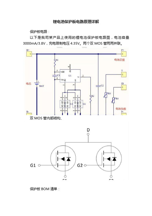
以下是我司某产品上使用的锂电池保护板电路图,电池容量3000mA/3.8V,充电限制电压4.35V。
两个双MOS管两两并联。
双MOS管内部结构、
保护板BOM清单:
过充保护:
以上是电池充电电流流向,可见两个双MOS管(U2、U3)全部导通,充电的时候U1的Pin5芯片会实时监听电芯正极电压,此电压相对Pin6,因为Pin6是U1的地参考。
当电芯正极相对Pin6大于过充门限电压时,Pin3控制关闭两个MOS管,此时停止充电,只能放电。
当放电到过充恢复电压以下时,Pin3控制的MOS 管重新打开,
这时可以充电。
过放保护:
以上是电池放电电流流向,可见两个双MOS管(U2、U3)全部导通,放电的时候U1的Pin5芯片会实时监听电芯正极电压,此电压相对Pin6,因为Pin6是U1的地参考。
当电芯正极相对Pin6小于过放门限电压时,Pin1控制关闭两个MOS管,此时停止放电,只能充电。
当充电到过放恢复电压以上时,Pin1控制的MOS 管重新打开,这时可以放电。
放电过流/短路保护:
以上是电池放电电流流向,可见两个双MOS管(U2、U3)全部导通,放电的时候U1的Pin2芯片会实时监听电压,此电压相对Pin6,因为Pin6是U1的地参考。
实际上这个电压就是两个MOS的导通压降,电流越大压降越大,当电压大于放电过流保护/短路保护电压时,Pin1管脚关闭两个MOS管。
以下是芯片MM3280JB7NRH的各种截止电压参数:。
BP3133A_CN_DS_Rev_1.0

测阈值时,功率管关断。 变压器原边峰值电流的计算公式为:
I P_PK
400 (mA) RCS
其中,RCS 为电流采样电阻阻值。 CS 比较器的输出还包括一个 500ns 前沿消隐时间。 LED 输出电流计算公式为:
I LED
I P_PK 4
NP NS
注 4:典型参数值为 25˚C 下测得的参数标准。 注 5:规格书的最小、最大规范范围由测试保证,典型值由设计、测试或统计分析保证。
5) (无特别说明情况下,VCC =15 V, TA =25 ℃) 描述 VCC 钳位电压 VCC 启动电压 VCC 欠压保护阈值 VCC 启动电流 VCC 工作电流 电流检测阈值 条件 1mA VCC 上升 VCC 下降 VCC= VCC-ON - 1V FOP=70KHz 388 输出短路 最小值 典型值 17 14 9 50 100 400 200 500 200 5 120 0.5 42 VGS=15V/IDS=0.5A VGS=0V/IDS=250uA VGS=0V/VDS=650V 650 1 9 100 150 412 最大值 单位 V V V uA uA mV mV ns ns KHz KHz V % Ω V uA
管脚封装
CS DRAIN DRAIN NC NC
XXXXXY: lot code W: 标示 X: 年号 YY:周号
BP3133A
VCC GND ROVP
图 2 管脚封装图
XXXXXY WXYY
管脚描述
管脚号 1 2 3 4 5,6 7,8 管脚名称 CS VCC GND ROVP NC DRAIN 描述 电流采样端,采样电阻接在 CS 和 GND 端之间 芯片电源 芯片地 开路保护电压调节端,接电阻到地 无连接,必须悬空 内部高压功率管漏极
电池低压保护电路

电池低压保护电路
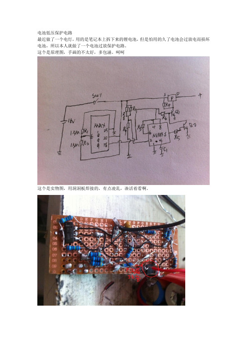
最近做了一个电灯,用的是笔记本上拆下来的锂电池,但是怕用的久了电池会过放电而损坏电池,所以本人就做了一个电池过放保护电路。
这个是原理图,手画的不太好,多包涵。
呵呵
这个是实物图,用洞洞板焊接的,有点凌乱,凑活着看啊。
原理图中用到了两个芯片,一个是max1999,这个芯片是从笔记本上拆下来的系统供电芯片,主要是为了用上边18脚输出的线性5伏,当然如果用专门的线性稳压器来输出线性5伏更好,体积会跟小的,另一个是ne555,这个芯片主要是用来当作比较器的,因为没有比较器手头上只有这个。
R1和r2是两个1.5M欧姆的电阻,r3是4.7k的电阻,r4是一个1.5M欧姆的电阻,r5是一个4.7k的电阻,r6是用四个4.7k的电阻并联而成,手中东西有限只能这样,见谅,r7和r8是两个并联的1.5M欧姆的电阻,r9是好几个电阻并联加串联成一个71k电阻,q1和q2是两个8050的npn三极管,q1上方的p是一个从笔记本拆下来的八角p沟道场管。
电池是四节笔记本锂电池串起来的十六伏。
元器件就这么多,按我上边的各个元器件大小直接焊接就可以用。
我用的最高是十六伏的电,电池最低放电到十二伏电池停止放电,必须在给电池充电到十二伏以上才可以继续放电。
他的工作原理是max1999主要是为了提供稳定的五伏输出,max1999的工作电压是5伏到24伏。
Ne555的2脚用来拾取电池的电压,当电压低于12伏的时候电压就输出了。
当然如果你改变r7,r8,和r9就可以改变保护的电池电压。
从五伏到十八伏都可以。
【最新】锂电池保护电路

【最新】锂电池保护电路锂电池是怎么保护电路和功能离子电池保护电路包括过度充电保护、过电流/短路保护和过放电保护,要求过充电保护高精度、保护IC功耗低、高耐压以及零伏可充电等特性.详细介绍了这三种保护电路的原理、新功能和特性要求.锂电池具有体积小、能量密度高、无记忆效应、循环寿命高、高电压电池和自放电率低等优点,与镍镉、镍氢电池不太一样,锂电池必须考虑充电、放电时的安全性,以防止特性劣化.针对锂电池的过充、过度放电、过电流及短路保护很重要,所以通常都会在电池包内设计保护线路用以保护锂电池.由于锂离子电池能量密度高,因此难以确保电池的安全性.在过度充电状态下,电池温度上升后能量将过剩,于是电解液分解而产生气体,因内压上升而发生自燃或破裂的危险;反之,在过度放电状态下,电解液因分解导致电池特性及耐久性劣化,从而降低可充电次数.锂离子电池的保护电路就是要确保这样的过度充电及放电状态时的安全性,并防止特性劣化.锂离子电池的保护电路是由保护IC及两颗功率 MOSFET所构成,其中保护IC监视电池电压,当有过度充电及放电状态时切换到以外挂的功率MOSFET来保护电池,保护IC的功能有过度充电保护、过度放电保护和过电流/短路保护.过度充电保护过度充电保护IC的原理为:当外部充电器对锂电池充电时,为防止因温度上升所导致的内压上升,需终止充电状态.此时,保护IC需检测电池电压,当到达4.25V时(假设电池过充点为4.25V)即激活过度充电保护,将功率MOS由开转为关断,进而截止充电.另外, 还必须注意因噪声所产生的过度充电检出误动作,以免判定为过充保护.因此,需要设定延迟时间,并且延迟时间不能短于噪声的持续时间.过度放电保护在过度放电的情况下,电解液因分解而导致电池特性劣化,并造成充电次数的降低.采用锂电池保护IC可以避免过度放电现象发生,实现电池保护功能.过度放电保护IC原理:为了防止锂电池的过度放电状态,假设锂电池接上负载,当锂电池电压低于其过度放电电压检测点(假定为 2.3V)时将激活过度放电保护,使功率MOSFET由开转变为关断而截止放电,以避免电池过度放电现象发生,并将电池保持在低静态电流的待机模式,此时的电流仅 0.1uA.当锂电池接上充电器,且此时锂电池电压高于过度放电电压时,过度放电保护功能方可解除.另外,考虑到脉冲放电的情况,过放电检测电路设有延迟时间以避免发生误动作.过电流及短路电流因为不明原因(放电时或正负极遭金属物误触)造成过电流或短路,为确保安全,必须使其立即停止放电.过电流保护IC原理为,当放电电流过大或短路情况发生时,保护IC将激活过(短路)电流保护,此时过电流的检测是将功率MOSFET的 Rds(on)当成感应阻抗用以监测其电压的下降情形,如果比所定的过电流检测电压还高则停止放电,计算公式为: V-=I_Rds(on)_2(V-为过电流检测电压,I为放电电流).假设V-=0.2V,Rds(on)=25mΩ,则保护电流的大小为I=4A.同样地,过电流检测也必须设有延迟时间以防有突发电流流入时发生误动作.通常在过电流发生后,若能去除过电流因素(例如马上与负载脱离),将会恢复其正常状态,可以再进行正常的充放电动作.锂电池保护IC的新功能除了上述的锂电池保护IC功能之外,下面这些新的功能同样值得关注:1. 充电时的过电流保护当连接充电器进行充电时突然发生过电流(如充电器损坏),电路立即进行过电流检测,此时Cout将由高转为低,功率MOSFET由开转为关断,实现保护功能.V-(Vdet4过电流检测电压,Vdet4为-0.1V)=I(充电电流)_Rds(on)_22. 过度充电时的锁定模式通常保护IC在过度充电保护时将经过一段延迟时间,然后就会将功率MOSFET关断以达到保护的目的,当锂电池电压一直下降到解除点(过度充电滞后电压)时就会恢复,此时又会继续充电-保护-放电-充电-放电.这种状态的安全性问题将无法获得有效解决,锂电池将一直重复着充电-放电-充电-放电的动作,功率MOSFET的栅极将反复地处于高低电压交替状态,这样可能会使MOSFET变热,还会降低电池寿命,因此锁定模式很重要.假如锂电保护电路在检测到过度充电保护时有锁定模式,MOSFET将不会变热,且安全性相对提高很多.在过度充电保护之后,只要充电器连接在电池包上,此时将进入过充锁定模式.此时,即使锂电池电压下降也不会发生再充电的情形,将充电器移除并连接负载即可恢复充放电的状态.3. 减小保护电路组件尺寸将过度充电和短路保护用的延迟电容集成到到保护IC里面,以减小保护电路组件尺寸.对保护IC性能的要求1. 过度充电保护的高精度化当锂离子电池有过度充电状态时,为防止因温度上升所导致的内压上升,须截止充电状态.保护IC将检测电池电压,当检测到过度充电时,则过度充电检测的功率MOSFET使之关断而截止充电.此时应注意的是过度充电的检测电压的高精度化,在电池充电时,使电池充电到饱满的状态是使用者很关心的问题, 同时兼顾到安全性问题,因此需要在达到容许电压时截止充电状态.要同时符合这两个条件,必须有高精度的检测器,目前检测器的精度为25mV,该精度将有待于进一步提高.2. 降低保护IC的耗电随着使用时间的增加,已充过电的锂离子电池电压会逐渐降低,最后低到规格标准值以下,此时就需要再度充电.若未充电而继续使用,可能造成由于过度放电而使电池不能继续使用.为防止过度放电,保护IC必须检测电池电压,一旦达到过度放电检测电压以下,就得使放电一方的功率MOSFET 关断而截止放电.但此时电池本身仍有自然放电及保护IC的消耗电流存在,因此需要使保护IC消耗的电流降到最低程度.3. 过电流/短路保护需有低检测电压及高精度的要求因不明原因导致短路时必须立即停止放电.过电流的检测是以功率MOSFET 的Rds(on)为感应阻抗,以监视其电压的下降,此时的电压若比过电流检测电压还高时即停止放电.为了使功率MOSFET的Rds(on)在充电电流与放电电流时有效应用,需使该阻抗值尽量低,目前该阻抗约为 20mΩ_30mΩ,这样过电流检测电压就可较低.4. 耐高电压电池包与充电器连接时瞬间会有高压产生,因此保护IC应满足耐高压的要求.5. 低电池功耗在保护状态时,其静态耗电流必须要小0.1uA.6. 零伏可充电有些电池在存放的过程中可能因为放太久或不正常的原因导致电压低到0V,故保护IC需要在0V时也可以实现充电.保护IC发展展望如前所述,未来保护IC将进一步提高检测电压的精度、降低保护IC的耗电流和提高误动作防止功能等,同时充电器连接端子的高耐压也是研发的重点.在封装方面,目前已由SOT23-6逐渐转向SON6封装,将来还有CSP封装,甚至出现COB产品用以满足现在所强调的轻薄短小要求.在功能方面,保护IC不需要集成所有的功能,可根据不同的锂电池材料开发出单一保护IC,如只有过充保护或过放保护功能,这样可以大大减少成本及尺寸.当然,功能组件单晶体化是不变的目标,如目前手机制造商都朝向将保护IC、充电电路以及电源管理IC等外围电路与逻辑IC构成双芯片的芯片组, 但目前要使功率MOSFET的开路阻抗降低,难以与其它IC集成,即使以特殊技术制成单芯片,恐怕成本将会过高.因此,保护IC的单晶体化将需一段时间来解决.锂电池保护板的电路图与工作原理关于锂离子电池的保护板电路,原理介绍,以及管理的书籍推荐.或者聚合物锂电池方面经典书籍。
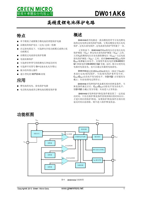
DW01AK6中文规格书

• 保护条件
正常状态下,如果电池放电使VDD端电压降低至过 电压放电保护阈值VOD,且持续时间超过过电压放电保 护延迟时间tOD,则 DW01AK6将使放电控制端DOUT由高电 平 转 为 VSS 端 电 平 ( 低 电 平 ), 从 而 使 外 接 放 电 控 制 N-MOS管Q2 关闭,放电回路被“切断”,即DW01AK6进
DW01AK6
高精度锂电池保护电路
特点
单节锂离子或锂聚合物电池的理想保护电路 高精度的保护电压(过充/过放)检测 在过放电情况下,可选择允许低功耗模式或禁止低 功耗模式 高精度过电流放电保护检测 电池短路保护 可选择多种型号的检测电压和延迟时间 可选择不同型号 0V-电池充电允许/禁止 极少的外围元器件 超小型化的 SOT23-6 封装
VDD=2.0V
V0V_CHG 充电器电压
电池电压, V0V_INH VM=-2.0V
最小值
典型值
最大值
单位
♦
1.5
10
V
VOCTYP-0.050
VOCTYP
VOCTYP+0.050
V
♦
VOCTYP-0.080
VOCTYP
VOCTYP+0.080
V
VOCRTYP-0.050 VOCRTYP VOCRTYP+0.050
DW01AK6 对每种保护/恢复条件都设置了一定的延 迟时间,只有在保护/恢复条件持续到相应的时间以后, 才进行相应的保护/恢复。如果保护/恢复条件在相应的 延迟时间以前消除,则不进入保护/恢复状态。
功能框图
VDD
电阻分压
VSS
基准源
基准源
基准源
单节锂电池充电管理芯片,IC电路图全集

产品特点1,可达500MA 充电电流,SOT23-5,单LED 指示灯,5V 输入线性降压,PW40542,可达1000MA 充电电流,SOP8-EP ,双LED 指示灯,5V 输入线性降压,PW40563,可达600MA 充电电流,SOT23-5,单LED 指示灯,5V 输入线性降压,输入输出短路保护4,可达2.50A 充电电流,SOP8-EP ,双LED 指示灯,5V 输入开关降压,PW40525,可达3.0A 充电电流,SOP8-EP ,双LED 指示灯,5V 输入开关降压,PW40356,可达2.0A 充电电流,SOP8-EP ,单LED 指示灯,5-20V 输入开关降压,PW42037,LDO 稳压芯片(2V-80V ),DC-DC 降压芯片,DC-DC 升压芯片选型表PW4054是一款性能优异的单节锂离子电池恒流/恒压线性充电器。
PW4054适合给USB 电源以及适配器电源供电。
基于特殊的内部MOSFET 架构以及防倒充电路,PW4054不需要外接检测电阻和隔离二极管。
当外部环境温度过高或者在大功率应用时,热反馈可以调节充电电流以降低芯片温度。
充电电压固定在 4.2V ,而充电电流则可以通过一个电阻器进行外部设置。
当充电电流在达到M A X 终浮充电压之后降至设定值的1/10,芯片将终止充电循环。
当输入电压断开时,PW4054进入睡眠状态,电池漏电流将降到1uA 以下。
PW4054还可以被设置于停机模式,此时芯片静态电流降至25uA 。
PW4054还包括其他特性:欠压锁定,自动再充电和充电状态标志⚫可编程充电电流500mA ⚫无需外接MOSFET ,检测电阻以及隔离二极管⚫恒定电流/恒定电压并具有可在无过热危险的情况下实现充电速率M A X 大化的热调节功能。
⚫精度达到±1%的4.2V 预充电电压⚫用于电池电量检测的充电电流监控器输出⚫自动再充电⚫充电状态输出显示⚫C/10充电终止⚫待机模式下的静态电流为25uA ⚫ 2.9V 涓流充电⚫软启动限制浪涌电流PW4065 是一款完整的单节锂电池充电器,带电池正负极反接保护、 输入电源正负极反接保 护的芯片,兼容大小 3mA-600mA 充电电流。
PW3130锂电池保护板电路芯片规格书

GENERAL DESCRIPTION FEATURESAPPLICATIONSTYPICAL APPLICATION CIRCUITPW3130系列产品是锂离子/聚合物电池的高集成度解决方案保护.PW3130包含先进的功率MOSFET ,高精度电压检测电路和延迟电路。
PW3130被放入一个超小型SOT23-5封装中,只有一个外部元件使其成为电池组空间有限的理想解决方案。
PW3130具有所有保护功能 在电池应用中需要包括过充电、过放电、过电流和负载短路保护等。
准确的过充检测电压,确保安全和充分利用正在充电在储存期间,低备用电流几乎不消耗电池中的电流。
该设备不仅适用于数字手机,也适用于任何其他锂离子和锂聚合物电池供电的信息设备需要长期的电池寿命。
⚫ 集成高功率MOSFET ,等效65mΩRDS(ON ) ⚫ 超小型SOT3-5包装⚫ 过温保护;过充电流保护;二步过流检测 ⚫ 过充电流;负载短路⚫ 充电器检测功能;0V 蓄电池充电功能;产生延时时间内部;高精度电压检测 ⚫ 低电流消耗;工作方式:2.8μA 型;断电模式:1.5μA 型 ⚫符合RoHS ,无铅(Pb )⚫ 单芯锂离子电池组 ⚫ 锂聚合物电池组PIN ASSIGNMENT/DESCRIPTIONPin NoPin Name Functions1 VT Test pin2 GND Ground, connect the negative terminal of the battery to this pin3 VDD Power Supply4,5VMThe negative terminal of the Charger . The internal FET switch connects this terminal to GNDVT GND VDD VMSOT-23-5L(TOP VIEW)VM12345ELECTRICAL CHARACTERISTICSTA = 25℃ParameterSymbol TestConditionMinTypMax UnitOvercharge Detection Voltage V CU 4.25 4.30 4.35 V Overcharge Release Voltage V CL 4.05 4.10 4.15 V Overdischarge Detection Voltage V DL 2.30 2.40 2.50 V Overdischarge Release Voltage V DR 2.903.00 3.10 VCharger Detection Voltage V CHA -0.12 V Overdischarge Current1 Detection I IOV1 V dd =3.5V 3.0 A Load Short-Circuiting Detection I SHORT V dd =3.5V12 A Current Consumption in Normal OperationI OPE V dd =3.5V ,V M =0V 2.80 μA Current Consumption in power DownI PDN V dd =2V,V M floating 1.50 6.0 μA Equivalent FET on Resistance R DSV dd =3.6V ,I VM =1A65 m Ω Over Temperature Protection T SHD+ 120 ℃ Over Temperature Recovery DegreeT SHD- 100℃Overcharge Voltage Detection Delay TimeT CU V DD =3.6V~4.4V 128 ms Overdischarge Voltage Detection Delay TimeT DL V DD =3.6V~2.0V 32 ms Overdischarge Current1 Detection Delay TimeT IOV1 V DD =3.6V 8.0 ms Load Short-Circuiting Detection Delay TimeT SHORTV DD =3.6V32 μSFunctional DescriptionPW3130监控电池的电压和电流,保护电池不受损坏过充电压、过放电电压、过放电电流和短路条件断开蓄电池与负载或充电器的连接。
简单的3.7v锂电池充电保护电路

1. 介绍3.7v锂电池充电保护电路的作用和重要性2. 分析3.7v锂电池充电保护电路的工作原理和组成部分3. 详细解释3.7v锂电池充电保护电路的设计要点和注意事项4. 探讨3.7v锂电池充电保护电路的改进和未来发展方向在现代电子设备中,3.7v锂电池是一种非常常见的电池类型。
然而,由于锂电池特性的限制,需要使用特定的电路来进行充电保护,以确保电池的安全和稳定性。
本文将介绍简单的3.7v锂电池充电保护电路,包括其作用、工作原理、设计要点和未来发展方向。
1. 介绍3.7v锂电池充电保护电路的作用和重要性3.7v锂电池充电保护电路是用来监控和控制锂电池充电过程的电路。
它的作用在于保护锂电池免受过充和过放的损害,并确保充电电流和电压在安全范围内。
这对于延长锂电池的使用寿命、提高其安全性和稳定性至关重要。
2. 分析3.7v锂电池充电保护电路的工作原理和组成部分3.7v锂电池充电保护电路主要由充电管理芯片、电池管理芯片和保护电路三个部分组成。
充电管理芯片负责控制充电电压和电流,以及监测电池的充电状态。
电池管理芯片则负责监测电池的电压、温度和状态,以及控制放电和充电过程。
保护电路主要由过压保护、欠压保护和温度保护三部分组成,可以在电池出现异常情况时及时切断充电或放电电路,保护电池和电路的安全。
3. 详细解释3.7v锂电池充电保护电路的设计要点和注意事项设计3.7v锂电池充电保护电路的关键要点包括合理选择充电管理芯片和电池管理芯片、确定合适的过压保护和欠压保护参数、合理布局电路以确保信号传输的稳定性和可靠性。
还需要注意电路的功耗、成本和体积,以及与其他电路的兼容性和可集成性。
在设计过程中还需要充分考虑到电池的特性和使用环境,尽量减小设计误差和风险。
4. 探讨3.7v锂电池充电保护电路的改进和未来发展方向为了提高3.7v锂电池充电保护电路的性能和可靠性,可以从以下几个方面进行改进:提高充放电效率和速度、降低静态功耗和过压波动、提高温度控制和保护的准确性、增强防误触发功能。
单芯片锂电池保护设计方案

为了防止锂电池在过充电、过放电、过电流等异常状态影响电池寿命,通常要通过锂电池保护装置来防止异常状态对电池的损坏。
目前锂电池的应用越来越广泛,从手机、MP3、MP4、GPS、玩具等便携式设备到需要持续保存数据的煤气表,其市场容量已经达到每月几亿只。
锂电池保护装置的电路原理如图1所示,主要是由电池保护控制IC和外接放电开关M1以及充电开关M2来实现。
当P +/P-端连接充电器,给电池正常充电时,M1,M2均处于导通状态;当控制IC检测到充电异常时,将M2关断终止充电。
当P+/P-端连接负载,电池正常放电时,M1,M2均导通;当控制IC检测到放电异常时,将M1关断终止放电。
图1:锂电池保护装置电路原理。
几种现有的锂电池保护方案图2是基于上述锂电池保护原理所设计的一种常用的锂电池保护板。
图中的SOT23-6L封装的是控制IC,SOP8封装的是双开关管M1,M2。
由于制造控制IC的工艺与制造开关管的工艺各不相同,因此图2中两个芯片是从不同的工艺流程中制造出来的,通常这两种芯片也是由不同的芯片厂商提供。
图2:传统的电池保护方案。
近几年来,业界出现了将几个芯片封装在一起以提高集成度、缩小最后方案面积的趋势。
锂电池保护市场也不例外。
图3中的两种锂电池保护方案A及B看起来是将图2中的两个芯片集成于一个芯片中,但实际上其封装内部控制器IC及开关管芯片仍是分开的,来自不同的厂商,该方案仅仅是将二者合封在一起,俗称“二芯合一”。
由于内部两个芯片实际仍来自于不同厂商,外形不能很好匹配,因此导致最终封装形状各异,很多情况下不能采用通用封装。
这种封装体积比较大,又不能节省外围元件,所以这种“二芯合一”的方案实际上并省不了太多空间。
在成本方面,虽然两个封装的成本缩减成一个封装的成本,但由于这个封装通常比较大,有的不是通用封装,有的为了缩小封装尺寸,需要用芯片叠加的封装形式,因此与传统的两个芯片的方案相比,其成本优势并不明显。
锂电3.7v保护板改装电路图

现在国内锂电池,3.7v良莠不齐,在放电电压在2.8v左右基本是极限了,如果到2.5v,好的电池还能充几次。
一般的电池,基本报废。
我买的保护板,有两种芯片(DW01、8205A),DW01取样芯片,8205A功率驱动芯片。
DW01取样:过放电压在2.35v~2.5v,过冲4.0v~4.19v。
要是买了这两个芯片的保护板,国内的锂电池3.7v基本报废,无报废的也充不了几次电。
解决办法:
①头尾并联1N5822( 肖特基二极管),1N5822正向电压0.52v,加上2.35v等于2.87v。
②1N5822串联到B+或B-极上。
③然后将3.7v电池串联在B或+B-上,这时保护板就算在2.35v但实际电池电压在2.87v。
有效保护过放。
说明:电池不能焊在保护板上,如果焊接,电池在充电会有0.52v损失,最好方法就是不焊接,用标准3.7V充电器充电,这样既能电池充满,在使用时又不会过放。
发一张保护板改装电路图。
- 1、下载文档前请自行甄别文档内容的完整性,平台不提供额外的编辑、内容补充、找答案等附加服务。
- 2、"仅部分预览"的文档,不可在线预览部分如存在完整性等问题,可反馈申请退款(可完整预览的文档不适用该条件!)。
- 3、如文档侵犯您的权益,请联系客服反馈,我们会尽快为您处理(人工客服工作时间:9:00-18:30)。
PW3133AOne Cell Lithium-ion/Polymer Battery Protection ICGENERAL DESCRIPTIONThe PW3133A series product is a high integration solution for lithiumion/polymer battery protection. PW3133A contains advanced power MOSFET, high-accuracy voltage detection circuits and delay circuits. PW3133A is put into an ultra-small SOT23-3 package and only one external component makes it an ideal solution in limited space of battery pack.PW3133A has all the protection functions required in the battery application including overcharging, overdischarging, overcurrent and load short circuiting protection etc. The accurate overcharging detection voltage ensures safe and full utilization charging. The low standby current drains little current from the cell while in storage. The device is not only targeted for digital cellular phones, but also for any other Li-Ion and Li-Poly battery-powered information appliances requiring longterm battery life.FEATURES● Protection of Charger Reverse Connection ● Protection of Battery Cell ReverseConnection● Integrate Advanced Power MOSFETwithEquivalent of 56mΩ RSS(ON) ● Ultra-small SOT23-3 Package● Only One External CapacitorRequired ● Over-temperature Protection ● Overcharge Current Protection● Two-step Overcurrent Detection :Overdischarge Current;Load Short Circuiting● Charger Detection Function ● 0V Battery Charging Function ● Delay Times are generated inside ● High-accuracy Voltage Detection ● Low Current Consumption: OperationMode: 2.8μA typ.Power-down Mode: 1.5μA typ.● RoHS Compliant and Lead (Pb) FreeAPPLICATIONS● One-Cell Lithium-ion Battery Pack ● Lithium-Polymer Battery PackTYPICAL APPLICATION CIRCUIT代理深圳夸克微科技Wuxi PWChip Semi Technology CO., LTDELECTRICAL CHARACTERISTICSTypicals and limits appearing in normal type apply for TA = 25oC, unless otherwise specifiedNote: The parameter is guaranteed by design .ParameterSymbol Test Condition Min Typ Max UnitDetection VoltageOvercharge Detection Voltage V CU4.254.30 4.35VOvercharge Release Voltage V CL 4.054.10 4.15VOverdischarge Detection VoltageV DL 2.3 2.4 2.5VOverdischarge Release Voltage V DR2.93.03.1VDetection CurrentOverdischarge Current1Detection *I IOV1V DD =3.6V3.5A Load Short-Circuiting Detection*I SHORT V DD =3.6V20ACurrent ConsumptionCurrent Consumption in Normal OperationI OPE V DD =3.6V VM =0V 2.86μA Current Consumption in power DownI PDNV DD =2.0VVM pin floating1.53μAVM Internal Resistance Internal Resistance between VM and V DD*R VMD VDD=2.0V VM pin floating 300k ΩInternal Resistance between VM and GND*R VMSV DD =3.6V VM=1.0V20k ΩFET on ResistanceEquivalent FET on Resistance *R SS(ON)V DD =3.6V I VM =1.0A56m ΩOver Temperature Protection Over T emperature Protection*T SHD+150oCOver T emperature Recovery Degree *T SHD-110Detection Delay TimeOvercharge Voltage Detection Delay Timet CU 80130200mS Overdischarge Voltage Detection Delay Timet DL 204060mS Overdischarge Current Detection Delay Time*t IOV V DD =3.6V 4816mS Load Short-Circuiting Detection Delay Time*t SHORTV DD =3.6V80180300uSFunctional Block DiagramOPERATIONThe PW3133A monitors the voltage and current of a battery and protects it from being damaged due to overcharge voltage, overdischarge voltage, overdischarge current, and short circuit conditions by disconnecting the battery from the load or charger. These functions are required in order to operate the battery cell within specified limits.The device requires only one external capacitor. The MOSFET is integrated and its RSS(ON) is as low as 56mΩ typical.Normal operating modeIf no exception condition is detected, charging and discharging can be carried out freely. This condition is called the normal operating mode.Overcharge ConditionWhen the battery voltage becomes higher than the overcharge detection voltage (VCU) during charging under normal condition and the state continues for the overcharge detection delay time (tCU) or longer, the PW3133A turns the charging control FET off to stop charging. This condition is called the overcharge condition. The overcharge condition is released in the following two cases:1, When the battery voltage drops below the overcharge release voltage (VCL), the PW3133A turns the charging control FET on and returns to the normal condition.2, When a load is connected and discharging starts, the PW3133A turns the charging control FET on and returns to the normal condition. The release mechanism is as follows: the discharging current flows through an internal parasitic diode of the charging FET immediately after a load is connected and discharging starts, and the VM pin voltage increases about 0.7 V (forward voltage of the diode) from the GND pin voltage momentarily. The PW3133A detects this voltage and releases the overcharge condition. Consequently, in the case that the battery voltage is equal to or lower than the overcharge detection voltage (VCU), the PW3133A returns to the normal condition immediately, but in the case the battery voltage is higher than the overcharge detection voltage (VCU),the chip does not return to the normal condition until the battery voltage drops below the overcharge detection voltage (VCU) even if the load is connected. In addition, if the VM pin voltage is equal to or lower than the overcurrent 1 detection voltage when a load is connected and discharging starts, the chip does not return to the normal condition.Remark If the battery is charged to a voltage higher than the overcharge detection voltage (VCU) and the battery voltage does not drops below the overcharge detection voltage (VCU) even when a heavy load, which causes an overcurrent, is connected, the overcurrent 1 and overcurrent 2 do not work until the battery voltage drops below the overcharge detection voltage (VCU). Since an actual battery has, however, an internal impedance of several dozens of mΩ, and the battery voltage drops immediately after a heavy load which causes an overcurrent is connected, the overcurrent 1 and overcurrent 2 work. Detection of load shortcircuiting works regardless of the battery voltage.Overdischarge ConditionWhen the battery voltage drops below the overdischarge detection voltage (VDL) during discharging under normal condition and it continues for the overdischarge detection delay time (tDL) or longer, the PW3133A turns the discharging control FET off and stops discharging. This condition is called overdischarge condition. After the discharging control FET is turned off, the VM pin is pulled up by the RVMD resistor between VM and VDD in PW3133A.Meanwhile when VM is bigger than 1.5V (typ.) (the load short-circuiting detection voltage), the current of the chip is reduced to the power-down current (IPDN). This condition is called power-down condition. The VM and VDD pins are shorted by the RVMD resistor in the IC under the overdischarge and power-down conditions. The power-down condition is released when a charger is connected and the potential difference between VM and VDD becomes 1.3 V (typ.) or higher (load shortcircuiting detection voltage). At this time, the FET is still off. When the battery voltage becomes the overdischarge detection voltage (VDL) or higher (see note), the PW3133A turns the FET on and changes to the normal condition from the overdischarge condition.Remark If the VM pin voltage is no less than the charger detection voltage (VCHA), when the battery under overdischarge condition is connected to a charger, the overdischarge condition is released (the discharging control FET is turned on) as usual, provided that the battery voltage reaches the overdischarge release voltage (VDU) or higher.When the discharging current becomes equal to or higher than a specified value (the VM pin voltage is equal to or higher than the overcurrent detection voltage) during discharging under normal condition and the state continues for the overcurrent detection delay time or longer, the PW3133A turns off the discharging control FET to stop discharging. This condition is called overcurrent condition. (The overcurrent includes overcurrent, or load short-circuiting.)The VM and GND pins are shorted internally by the RVMS resistor under the overcurrent condition. When a load is connected, the VM pin voltage equals the VDD voltage due to the load. The overcurrent condition returns to the normal condition when the load is released and the impedance between the B+ and Bpins becomes higher than the automatic recoverable impedance. When the load is removed, the VM pin goes back to the GND potential since the VM pin is shorted the GND pin with the RVMS resistor. Detecting that the VM pin potential is lower than the overcurrent detection voltage (VIOV1), the IC returns to the normal condition.Abnormal Charge Current DetectionIf the VM pin voltage drops below the charger detection voltage (VCHA) during charging under the normal condition and it continues for the overcharge detection delay time (tCU) or longer, the PW3133A turns the charging control FET off and stops charging. This action is called abnormal charge current detection. Abnormal charge current detection works when the discharging control FET is on and the VM pin voltage drops below the charger detection voltage (VCHA). When an abnormal charge current flows into a battery in the overdischarge condition, the PW3133A consequently turns the charging control FET off and stops charging after the battery voltage becomes the overdischarge detection voltage and the overcharge detection delay time (tCU) elapses.Abnormal charge current detection is released when the voltage difference between VM pin and GND pin becomes lower than the charger detection voltage (VCHA) by separating the charger. Since the 0 V battery charging function has higher priority than the abnormal charge current detection function, abnormal charge current may not be detected by the product with the 0 V battery charging function while the battery voltage is low.Load Short-circuiting conditionIf voltage of VM pin is equal or below short circuiting protection voltage (VSHORT), the PW3133A will stop discharging and battery is disconnected from load. The maximum delay time to switch current off is tSHORT. This status is released when voltage of VM pin is higher than short protection voltage (VSHORT), such as when disconnecting the load.Delay CircuitsThe detection delay time for overdischarge current 2 and load short-circuiting starts when overdischarge current 1 is detected. As soon as overdischarge current 2 or load short-circuiting is detected over detection delay time for overdischarge current 2 or load short- circuiting, the PW3133A stops discharging. When battery voltage falls below overdischarge detection voltage due to overdischarge current, the PW3133A stop discharging by overdischarge current detection. In thisPW3133Acase the recovery of battery voltage is so slow that if battery voltage after overdischarge voltage detection delay time is still lower than overdischarge detection voltage, the PW3133A shifts to power-down.Overcurrent delay time0V Battery Charging Function (1) (2) (3)This function enables the charging of a connected battery whose voltage is 0 V by self-discharge. When a charger having 0 V battery start charging charger voltage (V0CHA) or higher is connected between B+ and B- pins, the charging control FET gate is fixed to VDD potential. When the voltage between the gate and the source of the charging control FET becomes equal to or higher than the turn-on voltage by the charger voltage, the charging control FET is turned on to start charging. At this time, the discharging control FET is off and the charging current flows through the internal parasitic diode in the discharging control FET. If the battery voltage becomes equal to or higher than the overdischarge release voltage (VDU), the normal condition returns.Note(1) Some battery providers do not recommend charging of completely discharged batteries. Please refer to battery providers before the selection of 0 V battery charging function.(2) The 0V battery charging function has higher priority than the abnormal charge current detection function. Consequently, a product with the 0 V battery charging function charges a battery and abnormal charge current cannot be detected during the battery voltage is low (at most 1.8 V or lower).(3) When a battery is connected to the IC for the first time, the IC may not enter the normal condition in which discharging is possible. In this case, set the VM pin voltage equal to the GND voltage (short the VM and GND pins or connect a charger) to enter the normal condition.TIMING CHART1. Overcharge and overdischarge detectionOvercharge and Overdischarge Voltage Detection2. Overdischarge current detectionOverdischarge Current DetectionRemark: (1) Normal condition (2) Overcharge voltage condition (3) Overdischarge voltage condition (4)Overcurrent conditionVV CU -VV DL +V VDLONONCHARGEV DD Vov1VSS VVM Charger Load V CUV CU -V HCV DL +V DHV DLONDISCHARGE OFF V DD V V ov2V ov1V SSCharger Load(1)(4)(1)(1)(1)(4)(4)Charger Detection4. Abnormal Charger DetectionAbnormal Charger DetectionRemark: (1) Normal condition (2) Overcharge voltage condition (3) Overdischarge voltage condition (4) Overcurrent conditionVV CU -V V DL +V V DL ON Charger Load V DDV SSV VMVVCU -VV DL +VV DL ON ONCHARGE VDD V SS VVM Charger LoadTYPICAL APPLICATIONAs shown in Figure 6, the bold line is the high density current path which must be kept asshort as possible. For thermal management, ensure that these trace widths are adequate. C1 is a decoupling capacitor which should be placed as close as possible to PW3133A.PW3133A in a Typical Battery Protection CircuitPrecautions• Pay attention to the operating conditions for input/output voltage and load current so that the power loss in PW3133A does not exceed the power dissipation of the package.• Do not apply an electrostatic discharge to this PW3133A that exceeds the performance ratings of the built-in electrostatic protection circuit.PW3133A 11 PW3133A_2.3 PACKAGE DESCRIPTION SOT23-3无锡平芯微。
