液环式真空泵拆卸与装配步骤
水环真空泵安装方法
水环真空泵安装方法一、安装前的准备工作1.确定水环真空泵的正确型号和规格,以满足具体工艺要求。
2.准备好所需的安装工具和材料,包括水泵螺栓、管道连接件、密封胶等。
3.检查水环真空泵及其所有配件是否完好无损,并进行必要的清洁。
二、安装过程1.安装底座:将底座放置在水平平台上,确保底座与水平面保持一致,并用螺栓将底座固定在平台上。
2.安装底盘:将底盘放置在底座上,确保底盘与底座之间无松动。
然后使用螺栓将底盘固定在底座上。
3.安装电机:将电机放置在底盘上,然后使用螺栓将电机固定在底盘上。
注意在安装电机前应进行电机绝缘测试,并确保电机与底盘接地可靠。
4.安装水环:在水环真空泵的入口和出口处分别安装管道连接件,并用螺栓将其固定在底盘上。
确保管道连接紧密,无漏水现象。
5.安装进气阀门:将进气阀门连接到水环真空泵的入口管道上,并用螺栓将其固定在底盘上。
确保进气阀门密封良好,无泄露。
6.连接驱动装置:将电机与水环真空泵的驱动轴相连接,并紧固螺栓,确保连接牢固。
7.安装冷却水管道:将冷却水管道连接到水环真空泵的冷却水口上,并用螺栓将其固定在底盘上。
确保冷却水管路紧密密封,无漏水。
8.安装排气口:在水环真空泵的排气口上安装排气管道,确保排气管道畅通,并将其连接到使用的排气系统中。
9.安装仪表:根据需要,将真空计、压力计、温度计等仪表安装在适当的位置上。
10.确保所有连接紧固牢固,并使用扳手等工具适当拧紧螺栓,以防止泄漏和松动。
三、调试和运行1.打开冷却水阀门,确保冷却水流通。
2.打开进气阀门,观察水环真空泵是否正常启动,并检查泵体是否有异常振动和异响。
3.观察真空计、压力计、温度计等仪表的读数,确保水环真空泵工作正常。
4.检查排气管道是否有泄漏,并根据需要进行必要的调整和修复。
5.在运行过程中,定期检查水环真空泵的声音、温度等参数是否正常,并注意排出的水是否清澈。
注意事项:1.安装水环真空泵时需要确保底座平整、水平,并且能够承受水环真空泵及其配件的重量。
真空泵全装与拆卸方法
真空泵全装与拆卸方法说实话真空泵全装与拆卸方法这事,我一开始也是瞎摸索。
那时候看着真空泵就感觉挺懵的,不知道从哪儿下手。
就先说拆卸吧。
我第一次拆的时候,连螺丝都找不到全。
有的螺丝藏得那叫一个隐蔽,就像调皮的小精灵躲起来不让你找着。
我围着真空泵转了好几圈,才发现有几颗螺丝在一个小凹槽里。
这时候我就想啊,拆卸东西之前真得好好看一圈,就像我们剥洋葱,得先看看从哪儿剥更容易一样。
好不容易把螺丝都拧下来,可把零件拿出来的时候又出问题了。
有的零件卡得挺紧的,我当时也不敢太用力,怕给弄坏了。
结果稍微一使劲,零件是出来了,可我手上的劲儿还是不太均匀,“欸”,差点把旁边的小接口给弄坏了,这就教训我了,干啥得稳当一些。
全装呢,其实更需要小心。
我试过把零件从旧的真空泵拆下来装到新的上面去,可是零件多了就容易乱。
我拿着零件感觉每个都长得差不多啊,这就像从一堆双胞胎里找不同,可难了。
后来我就想了个笨办法,每拆一个零件我就拿张纸画一下它的位置,装的时候就按照这个来,还挺好用的。
但是有个小零件,看起来不起眼,我就没在意那个图到底画得准不准。
到装的时候,怎么也塞不进去那个位置,我又得重新调整别的零件才行。
所以啊,再小的零件也千万不能小瞧,得把它们的位置关系准准确确地给整明白咯。
还有啊,在全装的时候,密封的部分一定要仔细处理。
比如说那些密封垫圈,如果装歪了或者有点破损,那这真空泵工作起来可能就达不到想要的效果了。
这就像盖房子的时候,瓦片要是没铺好,下雨房子肯定漏水。
我之前就没太注意这个密封垫圈,装上之后老觉得漏气,又得拆开重新看垫圈的事儿。
对于真空泵的全装和拆卸,每次操作之前啊,一定要先确保你有合适的工具。
没有合适的工具,那可就像战士上战场没带武器,光看着活儿干着急。
像那种很小的螺丝,就得用专门的小螺丝刀,不然容易把螺丝拧花。
有一回我就用错了螺丝刀,结果螺丝花了,费了好大的劲儿才把那个螺丝弄下来。
反正呢,这个真空泵的全装与拆卸啊,得多尝试,犯错误是难免的,但是每一次错误都是让你下次做得更好的经验。
液环真空泵轴承更换

液环真空泵轴承更换
液环真空泵的轴承更换步骤如下:
1. 将液环真空泵停机并断开电源,确保安全操作。
2. 移除液环真空泵的外壳,通常需要使用螺丝刀或扳手来卸下螺丝。
3. 找到轴承部件,通常位于液环真空泵的转子部分。
根据具体型号和结构,可能需要移除一些其他零件才能暴露轴承。
4. 使用相应的工具将旧轴承从轴上取下。
可以使用轴承拔出器或敲击轴承来使其脱离。
5. 清洁轴承座和轴承孔,确保没有灰尘或杂质。
6. 使用适当的润滑剂涂抹新轴承,确保其顺利安装。
7. 将新轴承放在轴承座上,并用手或相应工具轻轻敲击使其正确安装。
8. 重新安装其他零件和液环真空泵的外壳。
9. 连接电源并进行测试,确保轴承更换成功。
请注意,以上步骤仅供参考,具体操作可能因液环真空泵型号和结构而有所不同。
在进行轴承更换时,请遵循液环真空泵的操作手册或向专业技术人员咨询。
SK系列水环式真空泵拆卸与装配及价格
【SK系列水环式真空泵】拆卸与装配:拆卸:泵的拆卸分为部分拆卸检和完全拆卸修理及更换零件,在拆卸前应将泵腔内的水放出.并将进气及排气拆下。
在拆卸过程中,应将所有的垫谨慎地取下,如发生损坏'应在装配时更抽象同样厚度的新垫。
泵应从后端(无联轴器一端)开始拆卸,其顺序如下:1 《松开并取下两连通管(SK-1.5/3无连通管);2 松开并取下后轴承压盖;3 用钩板手将圆螺母松开,取下填料压盖;4 松开填料压盖螺帽,取下填料压盖:5 松开泵体和端盖的联接螺栓和泵脚处的累栓;6 在泵体下加一支承,然后从轴上取下端盖;7 取下泵体。
泵的部分拆卸至此为止,此时泵的工作部分及各个进零件可进行检查及清洗。
完全拆卸,应按下列顺序继续进行;8 松开另一个泵脚螺栓,从底座上取下泵头;9 取下联轴器10 从轴上取下联轴器的键11 取下前轴承压盖;12 松开轴承备背帽,取下轴承架和轴承;13 松开填料压盖的压紧螺帽,取下填料压盖;14 将轴和叶一同从端盖中取出;15 从轴上取下轴套;16 从轴上取叶轮。
拆卸完毕,应将配合面和和螺纹仔细擦净涂上机油。
装配:①装配前清洗留在配合面上的垫并仔细擦净:②清除轴承和轴承架内的旧油并更换新油:③装配顺序与拆卸顺序相反。
装配时最主要的是调整叶轮端面和端盖上园盘的间隙,间隙的大小,直接影响泵的性能,两边总间隙按下表规定间隙,由泵体和端盖之间加垫获得,叶轮两端面间隙应均匀,可松紧轴套或背帽以移动叶轮来调整。
SK型分体式水环真空泵价格SKA、2BV水环式真空泵价格编号型号电压功率无电机带电机编号型号电压功率无电机带电机42 SK-1.5 3.0-4 2780 3545 33 SKA2060 0.81-2 194643 SK-3 5.5-4 3197 4518 34 SKA2061 1.45-2 208544 SK-6 11 *4 4726 6950 35 SKA2070 2.35-2 264145 SK-12 18.5-6 7645 11815 36 SKA2071 3.85-2 319746 SK-15 22 *6 10703 15568 37 SKA5110 4.0-4 430947 SK-20 37 *8 15985 26410 38 SKA5111 5.5-4 500448 SK-30 55 *8 18765 39615 39 SKA5121 7.5-4 653349 SK-42 75 *8 30580 53515 40 SKA5131 11 *4 83402SK双级水环式真空泵价格41 SKA5161 15 *6 13622 编号型号电压功率无电机带电机SK直联式水环真空泵价格50 2SK-1.5 4.0-4 3753 4726 型号电压功率无电机带电机51 2SK-3 7.5-4 4309 5838 SK-O.15 0.55-2 139052 2SK-6 15 *4 5421 8201 SK-0.4 1,5-2 159953 2SK-12 22 *6 11815 16680 SK-0.8 2.2-2 166854 2SK-15 30 *8 17097 25298 SK-1.5A 3.0-2 257255 2SK-2037 *82502035445SK-1.5B4.0-22711SZ 型水环式真空泵价格SHB 循环水真空泵价格型号 电压 功率 无电机 带电机 规格型号极限真空不含税运 含税运SZ-1 4.0-4 2711 3684 Pa(220V) (220V) SZ-27.5-433364865SHB-IIIA 6×10⁻² 1155 1386 SZB 水环式真空泵价格SHB-2IIIA 6×10⁻² 1568 1881 型号 电压 功率 无电机 带电机 SHB-95A6×10-2 2049 2459SZB-4 1.5-4 1390 2363SZB-82.2-415292502旋片式真空泵价格名 称规格型号抽气速率 极限真空不含税运价格含税运L/SPa 单相(220V)三相(380V)单相(220V) 三相(380V)皮带旋片式真空泵价格2X-4A4 6×10⁻² 1513 1478 1815 1774 2X-8A 8 6×10⁻² 3094 3713 2X-15A 15 6×10⁻² 4056 4868 2X-30A 30 6×10⁻² 6531 7838 2X-70A 70 6×10⁻² 9075 10890 直联旋片式真空泵价格2XZ-0.5 0.5 6×10⁻² 791 0 949 0 2XZ-1 1 6×10⁻² 859 0 1031 0 2XZ-22 6×10⁻² 1031 0 1238 0 2XZ-4 4 6×10⁻² 1238 1224 1485 1469 2XZ-2B 2 4×10⁻² 1306 1293 1568 1551 2XZ-4B4 4×10⁻² 1513 1499 1815 1799 2XZ-6B6 4×10⁻² 2750 2613 3300 3135 2XZ-8B 8 4×10⁻² 3438 4125 2XZ-15B 15 4×10⁻² 4675 5610 2XZ-25B25 4×10⁻² 8800 10560 防爆旋片式真空泵2XZF-0.50.56×10-21616151319391815价格2XZF-1 1 6×10⁻² 1788 1650 2145 1980 2XZF-2 2 6×10⁻² 2200 1925 2640 2310 2XZF-4 4 6×10⁻² 2956 2888 3548 3465 2XZF-6B 6 6×10⁻² 3438 4125 2XZF-8B 8 6×10⁻² 4469 5363 2XZF-15B 15 6×10⁻² 5844 7013 单级真空泵价格XZ-10.5 6×10⁻² 399 479 XZ-2 1.1 6×10⁻² 468 561 XZ-42.26×10-2619743名 称规格型号抽气速率 极限真空含税出厂价含税出厂价 L/SPa 单相(220V)三相(380V)单相(220V) 三相(380V)无油真空泵价格WXZ-1 16×10-21375 1341 1650 1609 WXZ-2 26×10-2 1581 1547 1898 1856 隔膜真空泵价格LH-85 30(L/min ) 0.085Mpa 1031 1238 LH-85L 30(L/min ) 0.085Mpa 1169 1403 LH-95D 30(L/min ) 0.095Mpa 1361 1634 LH-85DL60(L/min ) 0.085Mpa13611634。
真空泵的拆卸
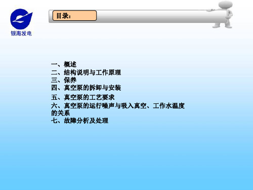
二、结构说明与工作原理
4.水环真空泵所需的工作水和补充水从接口N3.3进入,泵在运 行中补充水压力最好保持在0.15~0.3MPa abs(如果水源来自凝 结水系统,压力较大,需采用减压阀减压,本套机组提供用户时 已配有减压阀及过滤器,安装时必须装在接口N3.3管路上,过滤 器装在减压阀之前)。低水位控制器(22a)使水位保持在最低水位 之上。高水位溢流管(22b)用以限制最高水位,过量的水从N4.6 处排出。气水分离器的水位由液位计(23)指示。水环真空泵的工 作水和补充水尽可能采用清洁软水。
二、结构说明与工作原理
二、结构说明与工作原理
2.当泵工作时,被抽气体与部分工作水经泵的排气三通(17)进 入气水分离器(8),气体与水分离后,气体可于室内直接排放,也 可通过管道排于室外,但管路直径不应小于分离器排出口的口径, 且管路应尽可能短,否则会增加排气阻力,影响泵性能。
3.水环真空泵工作时(形成水环)需要工作水。泵工作中产生的 气体压缩热和泵吸入的混合气体中蒸汽的热量被工作水所吸收, 这些工作水随同被抽气体不断从泵的出口排到气水分离器,经气 水分离器分离后,进入管路(26),经热交换器(13)冷却,工作水 由管路(28)再次进入水环泵形成供水循环。热交换器的冷却水, 水质应清洁,水压应小于1MPa(一般采用0.3~0.6MPa abs),水 温尽可能较低。
三、保养
4.填料适当压紧,松紧程度可通过填料压盖上 的螺栓调节,填料经长时期使用后不能进一步调 整时,应更换新的填料。更换时,移去旧填料, 并清洗填料函。装填料时,填料的切口位置应错 开90º。
5.当泵的性能明显下降,轴功率增大,应打开 泵排出侧的观察孔盖,检查阀板有否塑性变形或 损坏(阀板材料为聚四氟乙烯,属易损件,一般使 用3个月左右应观察检查),必要时更换新阀板。
1、液环真空泵2BE1 101-253安装使用说明书

尊敬的肯富来用户们:承蒙选购、使用KENFLO产品,谨致万分谢意。
本说明书提供了安装、使用和维修2BE1 101~253水环真空泵时必须注意的事项和指导,因此在安装使用水环真空泵前,有关技术、操作人员必须首先详细阅读,以期经久耐用。
对于运输、装配、使用、维护等过程的注意事项和技术要求,即使在本说明书中没有明确提出,但也可能由于不注意而造成直接或间接的人身伤害或设备事故,所以也要注意安全。
声明:1、本说明书已注明各种安全预防措施,请用户在操作和使用维护中必须时刻留意。
用户错误或疏忽使用本说明书中的信息而导致的损害由用户承担全部责任。
2、本说明书不可能包括2BE1 101~253水环真空泵的安装和操作维护保养所有的详细内容,无法涉及操作维护保养中可能出现的每种情况。
如果您希望得到其它信息,或遇到本说明书中未提及的其它问题,请向本公司索取有关资料。
3、用户所订购本公司生产的水环真空泵及机组,其材质及结构是本公司根据用户提出的工况(包括工作介质、温度、工作液和环境情况)下进行设计和选用材料的,请不要随意改动你的水环真泵的工作介质和使用环境,或用作其它用途,否则会引起泵的寿命减少和损坏水环真空泵及机组,甚至会导致人员的死亡、重伤或重大设备事故等。
4、本说明书为广东省佛山水泵厂有限公司倾心汇编。
然而,用户的系统千差万别,本公司不能保证本说明书的完整性,因此,该说明书可能存在不足之处。
购买者、使用者应始终负责验证信息的准确性,并采取安全措施。
5、广东省佛山水泵厂有限公司任何时候有权对其产品的结构和设计及相关文件资料作出修改。
说明书中的数据与最近付印的一致,所有资料以最新修改版本的数据为准,所有技术资料的修改不再通知客户,也不再给客户更换新资料。
一、安全1、安全术语及标志提到的安全术语有:有采取正确预防措施,将导致死亡、重伤或重大设备事故。
有采取正确预防措施,可能导致死亡、重伤或重大设备事故。
:表示对某些技术细节提请特别注意,因为有时资深人员对这些事项也可能忽略。
Sz-2型水环式真空泵
Sz-2型水环式真空泵标准的话语权和主导权。
由于历史原因和区域原因,目前ISO/TC153“阀门”已形成已欧美为主体的格局。
因此,全国阀门标委会一方面积极主动地参加并主办国际标准会议;另一方面,积极派出我国的专家加入到国际组织的标准委员会“TC”、分委会“SC”和标准工作组“WC”,认真对待国际标准草案的投票,并将对我国有利的条款提供给ISO/TC153秘书处,使国际标准中能体现我们的合理要求。
自控阀门行业的发展瓶颈自控阀门指的是利用电动、气动、液动或电磁驱动等人力以外的方式,对阀门进行控制。
其特点是:使用方便、安全;可以现场控制,也可以远距离控制;可以对单一阀门进行控制,也可以对多部阀门进行集中控制;可以进行简单的开关控制,也可以实现调节控制;配合电子计算机,可以实现程序化控制。
我国目前的自控阀门主要有电动蝶阀、气动蝶阀、电动球阀、气动球阀、电动调节阀、气动调节阀等电动阀门,气动阀门构成。
除中低压及精密要求较为普通的自控阀门制造水平能达到国外市场要求外,高压及精密度要求高,调节性能准确性严格的主要依靠国外进口。
目前自控阀门市场首要存在诸多问题,首先,有的经营者图便宜,买着无厂无名的阀门,打上著名厂家的铭牌及合格证,对正规阀门企业的名誉造成极大损害。
其次,缺乏创新阀门,有些经营者经过对废旧阀门简单除锈后油漆二次出售,给工程质量带来极大的安全隐患。
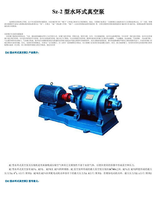
透过对自控【SZ型水环式真空泵】产品简介:SZ型水环式真空泵及压缩机是用来抽吸或压缩空气和其它无腐蚀性不溶于水的气体,以便在密闭的容器中形成真空和压力。
SZ型水环式真空泵有SZ-1、SZ-2、SZ-3及SZ-4四种规格,SZ真空泵所形成的最大真空度分别在86~95%之间。
SZ-1及SZ-2所能形成的最大压力为1.0~1.4公斤/厘米2,SZ-3及SZ-4在所配电动机功率容许下的最大压力为1.5公斤/厘米2,若增加电动机功率,最大压力为2.1公斤/厘米2【SZ型水环式真空泵】型号意义:【SZ型水环式真空泵】结构说明:SZ型水环式真空泵的结构如图所示:SZ型水环式真空泵由泵体(1)及两个侧盖(2)(3)所组成(图3及图4)侧盖下部有泵脚(a)支撑(图2),在上部是两管子即进气管(c)和排气管(f),这两个管子通过侧盖上的吸气孔(d)及排所孔(g)与泵腔相连,泵体上的进气管与排气管和侧盖上的吸气孔及排气孔相通,轴(4)偏心地安装在SZ型水环式真空泵体中,叶轮(6)用键(5)固定于轴上。
水环式真空泵装配前的准备及安装过程--自平衡多级泵
水环式真空泵装配前的准备及安装过程
装配水环式真空泵前应先将各零部件的结合面仔细清洗干净,所有配合表面和螺纹应仔细擦净并涂上机油,清除掉滚动轴承和轴承架内的旧油,准备好需要的垫,然后按下列顺序顺行装配。
(1)将水环式真空泵叶轮装到轴上,再装上轴套和螺母。
(2)将水环式真空泵泵体和后盖连接上,送入转子后再装上前盖。
(3)装上水环式真空泵填料函和前后轴承架,再装上后轴承,并用螺母固定.调整叶轮与前后端盖的问隙.然后装上前后轴承盖。
(4)装上水环式真空泵泵联轴器。
(5)调整水环式真空泵叶轮与前后盖之间的端面间隙,SZB-3和SZB-4不得超过0.4mm. SZB-1和SZB-2不得超过0.3mm.间隙是靠泵体和前后盖之间加纸垫来获得。
(6)为使水环式真空泵两边的间隙均匀,可用轴套来调整。
先将后轴定位.并将叶轮端而钻紧在后盖端面上.然后调整后轴套,使叶轮向联轴器方向移动总间隙的一半左右,再将前轴套压紧在叶轮上即可。
(7)装上水环式真空泵填料,把紧填料压盖.
(8)装配好的水环式真空泵,应用手盘动联轴器,需轻快均匀,无卡阻为合格。
真空泵拆卸施工方案(3篇)

第1篇一、前言真空泵作为一种重要的机械设备,广泛应用于化工、制药、食品、石油、电子等行业。
在设备运行过程中,由于各种原因,可能会需要对真空泵进行拆卸和维修。
为确保拆卸施工的安全、高效和顺利进行,特制定本施工方案。
二、施工准备1. 工具准备(1)扳手、螺丝刀、钳子等常用工具;(2)专用拆卸工具,如拆卸真空泵的专用扳手、拆卸轴承的专用工具等;(3)液压千斤顶、起重设备等辅助工具。
2. 材料准备(1)润滑油、密封胶等辅助材料;(2)备品备件,如轴承、密封件等。
3. 人员准备(1)施工人员应具备一定的机械维修知识和操作技能;(2)施工人员应熟悉真空泵的结构和原理;(3)施工人员应掌握安全操作规程。
三、拆卸步骤1. 安全检查在拆卸前,应对真空泵进行全面的安全检查,确保无安全隐患。
检查内容包括:电气线路、传动装置、润滑系统等。
2. 断电在拆卸前,应先切断真空泵的电源,确保安全。
3. 泄放压力拆卸前,应将真空泵内部的压力泄放至安全值,防止在拆卸过程中发生意外。
4. 拆卸步骤(1)拆卸外部附件:如冷却器、电机、进出口管道等;(2)拆卸轴承座:使用专用工具拆卸轴承座,注意保护轴承;(3)拆卸轴承:拆卸轴承时,注意保护轴承,防止损坏;(4)拆卸叶轮:使用专用工具拆卸叶轮,注意保护叶轮;(5)拆卸密封件:拆卸密封件时,注意保护密封件,防止损坏;(6)拆卸泵体:拆卸泵体时,注意保护泵体,防止损坏。
四、拆卸注意事项1. 注意安全操作,防止发生意外伤害;2. 严格按照拆卸步骤进行,避免因操作不当导致损坏;3. 注意保护零部件,避免损坏;4. 在拆卸过程中,如发现异常情况,应立即停止拆卸,检查原因,待排除后继续施工;5. 拆卸后的零部件应妥善保管,避免丢失。
五、施工总结1. 施工过程中,严格按照拆卸步骤进行,确保拆卸过程安全、高效;2. 施工过程中,注意保护零部件,避免损坏;3. 施工过程中,严格按照安全操作规程进行,确保施工安全;4. 施工完成后,对拆卸的零部件进行清理、检查,确保零部件完好;5. 施工完成后,对施工过程进行总结,为今后的施工提供参考。
NASH液环泵操作规程
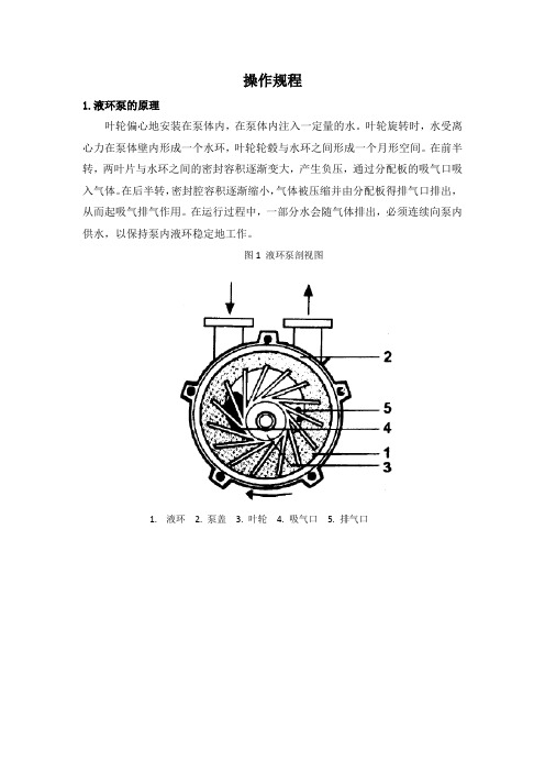
操作规程1.液环泵的原理叶轮偏心地安装在泵体内,在泵体内注入一定量的水。
叶轮旋转时,水受离心力在泵体壁内形成一个水环,叶轮轮毂与水环之间形成一个月形空间。
在前半转,两叶片与水环之间的密封容积逐渐变大,产生负压,通过分配板的吸气口吸入气体。
在后半转,密封腔容积逐渐缩小,气体被压缩并由分配板得排气口排出,从而起吸气排气作用。
在运行过程中,一部分水会随气体排出,必须连续向泵内供水,以保持泵内液环稳定地工作。
图1 液环泵剖视图1.液环2. 泵盖3. 叶轮4. 吸气口5. 排气口图2 2BV6水环式真空泵/压缩机图3 22BW5水环式真空泵/压缩机2.设备型号参数3.流程图300P0305ab蒸发真空泵流程图300PA0601 氢气压缩机流程图4.操作步骤4.1 准备应根据流程图和尺寸图进行检查以保证管路和ELMO-F 真空泵在整个布局中的安装是正确的。
在第一次启动泵前,一定要用手或其他合适工具盘动泵轴。
泵轴旋转方向要通过点动电机进行检测,以保证与泵上所标箭头方向一致。
排气口(N2.2)必须全开,另外压力表(012、480)和压力开关的截止阀(013)也要打开,阀(242、245、249)一定要关闭。
工作液一定要供至N3.3 接口,冷却水供至N5.0 接口。
第一次试车前,开车后约4 周及长时间停车后,真空泵应用洁净水(软水)进行清洗,这一点非常重要。
4.2 泵的注水通过法兰接口 N3.3 向闭环真空系统内注入工作液(如果需要,打开旁通阀,可加速泵的灌注)。
同时通过管线(260)、换热器130 及管线(280)向ELMO -F 真空泵充水分离器内水位提高,补水电磁阀停止水的供应时,充水过程完成。
分离器内的水位可通过液位计(230)监测,大约5 分钟后重新检查水位(此时平衡已建立)。
4.3 启动启动电机(030),冷却水阀及系统进气阀同时打开,ELMO-F 真空泵即投入运行当水环立起来后,系统进入工作状态。
4.4 停车1)停真空泵(010)的驱动电机(030)。
拆卸更换水环式真空泵机封步骤
拆卸更换水环式真空泵机封步骤
关键词:拆卸,机封,真空泵,轴承,机械密封
核心提示:本文汇总了水环式真空泵机封拆卸更换的步骤。
1、拆掉真空泵两端机封的冷却水管;
2、拆卸动力端皮带轮(更换非动力端机封时无这一步);
3、分别把动力端和非动力端的机封拆下挂在轴上,注意轻拆轻放;这一步尤其重要,避免了损坏完好端的机封。
(注意:如果是单独检修两端的轴承,这一步也是必须的);
4、拆下要更换机封端的轴承压盖,卸下轴承锁紧背帽;
5、用顶丝把轴承座连同轴承一起顶出拆下。
(此时需要用葫芦从拆装端吊住轴,方便轴承的顶出);
6、把检查完好后的新机封小心地套在轴上;
7、把旧机封从轴上取下;
8、清洗检查轴承是否完好、检查轴承间隙是否合适;
9、把轴承、轴承座回装轴上,并为轴承加上润滑油脂,上紧内圈锁紧背帽,装上轴承压盖(这一步也需要葫芦吊轴配合);
10、试盘车看看是否轻松,特别注意此盘车过程中别损坏机封;
11、分别把两端的机封从轴上回装至密封箱里面;
12、回装皮带轮(检修非动力端时无这一步);
13、回装冷凝水管,通进冷凝水后盘车试漏;
14、检修完毕,工完场清。
文章来源:密封技术网
相关推荐:机械密封 ;
油封 ;。
TRVB 32-25液环真空泵单级机械密封拆装说明书
(Rev. 2.1_06-2022)DISASSEMBLY AND ASSEMBLY INSTRUCTIONSFORLIQUID RING VACUUM PUMP SINGLE STAGEWITH MECHANICAL SEALTRVB 32-25Disassembly and assembly instructions for liquid ring vacuum pump with mechanical seal2INTRODUCTIONThese instructions are for the maintenance staff to repair the following pump:TRVB 32-25These instructions are supplied together with the manual of “INSTALLATION, OPERATION AND MAINTENANCE INSTRUCTIONS FOR LIQUID RING VACUUM PUMPS”.They provide a reference for safe operation, installation, maintenance and repairing of the pumps.Prior to working on the pump it is recommended to follow the instructions of safety listed in chapters 2 and 15 of the above manual, as well is absolutely important to:- wear safety clothing, hard hat, safety shoes, safety eyeglasses - disconnect the electrical power- close suction valves and service liquid valves- remove pump from installation without damaging other system components - assume all safety measures if pump has been handling hazardous fluids- drain pump casings through the draining connections and flush the pump with clean liquid, if required.When requesting spare parts or technical information for the pump, always quote the pump model number and serial number which is printed on the pump nameplate: therefore, it is recommended not to remove the pump nameplate or, in case this action will be necessary, write the serial number on the pump (for example on the flange).Should additional information be required, please do not hesitate to contact POMPETRAVAINI or the closest representative. Should there be any difficulties in repairing the pump, it is recommended to send the pump for repair to POMPETRAVAINI or the local authorised representative.Any pump repairs and/or system work carried out by others will not be guaranteed by POMPETRAVAINI.NOTE: VDMA numbers identify all pump components.Refer to parts list in chapter 4 and to the section drawing in chapter 5. All drawings are schematic only and are not certified for construction.For further information please consult POMPETRAVAINI or its closest representative. Torque values for various bolt sizes and tie-bolts are listed on fig. 4.INDEX1 -Pump disassembly 2 - Pump assembly3 - Recommended spare parts4 - Parts list5-Typical sectional drawingsThe liquids and the gases handled by the pumps and also their parts could be potentially dangerous for persons and environment: provide their eventual disposal in conformity with the laws into force and a proper environment management.The present manual is not assigned for pumps subjected to the ATEX 94/9/CE directive. In case the pump is assigned in environments subjected to the application ATEX 99/92/CE directive or in case the pump is provided with a nameplate indicating the ATEX stamp, it strictly forbidden proceed to start up the pumps but necessary to consult POMPETRAVAINI for clarifications.For pumps subjected to the ATEX 94/9/CE directive it is available a dedicated integrative manual.In preparing this manual, every possible effort has been made to help the customer and operator with the proper installation and operation of the pump.Should you find errors, misunderstandings or discrepancies please do not hesitate to bring them to our attention.Disassembly and assembly instructions for liquid ring vacuum pump with mechanical seal3Disconnect the pump from the electrical motor VDMA 801 unscrewing the screws VDMA 901.3.Place the pump in the vertical position resting on the lantern VDMA 341, remove the screws VDMA 914 and then remove the pump casing VDMA 101 from the rest of the pump.Remove the screws VDMA 914.1 that hold the metal cover VDMA 180.6 on the inspection port of the pump.Check that the components of the special valve VDMA 180.5 and Teflon flapper VDMA 400.9 are in good working conditions.Verify that the internals of suction/discharge casing VDMA 101 are free of defects (wear, corrosion, cracks, etc.).Remove the shaft nut(s) VDMA 923 or 923.1 and then the impeller VDMA 230. Verify that the impeller is also free from defects and wear.Remove the shaft key VDMA 940.1 and the spacer VDMA 485.Remove the rear casing VDMA 120 by removing the screws VDMA 901.1.The rotating part of the mechanical seal VDMA 433.2 will also slide out of the shaft.The stationary part of the mechanical seal can now be removed from the rear cover. Note the threaded anti-rotating pin VDMA 904 for the mechanical seal stationary part.Remove the thrower VDMA 507 from the shaft VDMA 210, remove the circlip VDMA 932.3 from the lantern VDMA 341. Now remove the shaft VDMA 210 with the ball bearings VDMA 320, remove the circlip VDMA 932. With a proper puller remove the ball bearings VDMA 320 from the shaft and, if necessary, remove also the elastic ring VDMA 935 placed at the bottom of the lantern VDMA 341.Proceed with the inspection of all components, replace bad and/or worn parts with POMPETRAVAINI’s original parts. It is good practice to replace, as a minimum, all wear parts such as mechanical seal, gaskets, etc.Begin the assembly by placing the lantern VDMA 341 in the vertical position resting on the larger flange. Place the elastic ring VDMA 935 at the bottom of the lantern (if previously removed).Insert on the shaft VDMA 210 the 2 ball bearings VDMA 320 type 6006-2RS (30x55x13) locking the ball bearing on the pump side by the circlip VDMA 932, insert the sub-assembly (shaft and bearings) into the lantern VDMA 341 pushing it compressing the elastic ring VDMA 935, fit the circlip VDMA 632.3.Insert on the shaft the thrower VDMA 507.Insert the stationary part of the mechanical seal VDMA 433.2 in the rear casing VDMA 120.Lubricate the seal O-Ring with compatible liquid, (mechanical seal dimensions are listed in fig. 1).Be sure that the seal stationary seat does not come out of its seat. Insert on the shaft VDMA 210 the rear casing VDMA 120 and connect it to the flange of the lantern VDMA 341 with the screws VDMA 901.Do not tighten the screws VDMA 901.Check the impeller length against the depth of casing VDMA 101 in which the impeller must fit (see fig. 2 for allowed tolerance). In the event the impeller is too long it will be required to machine it down.A pre-assembly of spacer VDMA 485 and impeller VDMA 230 onthe shaft is required. If needed, add shims between the spacer and the impeller so that the latter is 0,05 to 0,10 mm from the rear casing VDMA 120 (thiswill provide an even clearance on both sides of the impeller) see fig. 3. Remove the impeller and the spacer with the shims, if previously added.Proceed with the final pump assembly: lubricate the O-ring and shaft then insert on the shaft the rotating part of the mechanical seal VDMA 433.2.Be sure to keep both seal faces clean. Insert on the shaft the spacer VDMA 485 with shims (if needed).Fig .1Disassembly and assembly instructions for liquid ring vacuum pump with mechanical seal4Push the spacer to compress the seal spring and insert the shaft key VDMA 940.1 in the keyway. Insert the impeller and lock it on the shaft with the impeller nut(s) VDMA 923 or 923.1. Torque values are listed in fig. 4.Fit the 2 locating pins VDMA seats (if previously removed).pins for guide.with the screws VDMA Place the pump assembly in and, using a level, check 901.3 that attach the lantern VDMA 801.Check the free rotation of fan side.Allow the pump gasket toFig. 4 - TORQUE VALUES FOR BOLTS AND NUTS OF VARIOUS DIAMETERSWhen ordering the pump it is good practice to also order the necessary spare parts, especially when there are no stand-by pumps in the installation.This will minimise unnecessary down times in the event of pump failures or routine maintenance.It is therefore, recommended to stock the following spare parts for each pump size:1 Impeller1 Shaft assembly2 Ball bearings1 Mechanical seal1 Gasket compound1 Electric motorFor better parts management, the VDMA 24296 standards suggest to stock the number of parts as a function of the number of pumps being used in the plant.On the pump nameplate are printed the pump model, year of manufacture and pump serial number. When ordering spare parts always refer to this information.Pump type, parts item number (VDMA) and description (from the parts list on chapter 3 and pump sectional drawing on chapter 4) is useful information that helps us supplying the correct spare parts for your pump.We recommend the use of original parts: in case of deviation, POMPETRAVAINI declines any responsibility for damages that may be derived from the use of non-original spare parts.According to what expected from 2012/19/UE Directive on Waste Electric and Electronic Equipment the electrical pump assembly from us supplied (pump coupled with an electrical motor of Pompetravaini supply or customer supply) placed on the market after the 15th of August 2018 fell within the limits of application of the Directive. As a consequence, conforming to article 14 of the 2012/19/UE Directive of the European Parliament of the 4th of July 2012, Pompetravaini Spa is registered on the Italian list of EEE manufacturer. The electrical pump assembly supplied by Pompetravaini Spa that should be discontinued from use must not be disposed with common waste because it is composed of different materials that can be recycled at the appropriate facilities. If it is not intended to proceed autonomously at the management of the electrical pump assembly at authorized disposal companies it is possible to contact the Pompetravaini branch closer to you that will give you the necessary information on a proper disposal in accordance with mandatory laws. The pump unit must be previously cleaned up by the pumped product upon disposal.After reclamation the electrical pump assembly is not potentially dangerous for human health and environment, not containing harmful substances according to 2011/65/UE (RoHs) Directive, but if abandoned in the environment will have a negative impact on the ecosystem.Sending the electrical pump assembly to an adequate process of disposal and recovery of materials protect the environment and help to limits consumption of available resources with effective recycling of materials. The abandonment in the environment of the apparatus or the illegal disposal of the same are punished by law.Disassembly and assembly instructions for liquid ring vacuum pump with mechanical seal 5Disassembly and assembly instructions for liquid ring vacuum pump with mechanical seal6TRVB 32-25 (with NEMA electric motor - type D143TCZ – 2 poles – kW 1,1 – Hz 60 – V 415)Applicable only for Stainless steel material(Blank page)Disassembly and assembly instructions for liquid ring vacuum pump with mechanical seal 7Disassembly and assembly instructions for liquid ring vacuum pump with mechanical seal832.GB00 / PRINTED IN ITALYSmontaggio TRVB 32-25 IngleseContinuing research of POMPETRAVAINI results in product improvements: therefore any specifications may be subject to change without notice.20022 CASTANO PRIMO (Milano) ITALY Via per Turbigo, 44 Tel. +39 0331 889000 。
液环真空泵轴承更换
液环真空泵轴承更换
更换液环真空泵轴承时,可以按照以下步骤进行操作:
1. 拆下循环水的供水管路及真空泵进口管路和出气管路。
2. 拆卸真空泵泵体上面的紧固螺栓,将泵盖取下,随后用工具取出叶轮及键。
3. 水环式真空泵除了SKA水环真空泵采用机械密封以外都是采用填料密封,SZB型也属于填料密封形式,需要先拆卸填料压盖,然后再操作。
4. 将里面的填料及填料环取出。
5. 把真空泵与支架的连接螺栓松掉,把整个泵体取下来。
6. 如果需要拆卸泵轴和轴承,必须先把轴承箱里面的润滑油放干净,然后再拆卸轴承盖板和联轴器,向泵体方向拆卸泵轴即可。
在更换轴承时,要注意加热轴承至80~100℃,不要猛烈敲击轴承,换轴承润滑脂时建议更换磨损了的密封件。
实际操作中,建议根据具体的真空泵型号和使用情况,按照设备制造商提供的维修手册进行操作。
TFVP350D 双级液环真空泵拆装维护说明书

5.3 拆卸传动侧轴承部件 和拆卸非传动侧轴承部件的方法相同。 传动侧滚柱轴承内圈的拆卸方法可以参照 5.2.11
5.4 拆卸两端填料部件(如图 5-03 所示) 5.4.1 松开压紧螺栓,取出填料压盖 5.4.2 取下填料和填料环(填料可以用铁钩钩出)
图 5-03 5.5 拆卸主体部件
分配器设计,叶轮与分配器的间隙小,效率高。 无排气阀片部件,减少故障点。 无轴套,采用喷涂高硬度耐磨不锈钢,降低日后维修费用。 高效率,低功率,降低能耗,节约费用。同时热量产生少,提高了换热器效率。 成套机组配置上板式或管式热换器,工作液与冷却液可以完全分离,保证冷凝水系统纯净。 轴封可为填料密封或机械密封,可满足不同的轴封需要。 三、泵的工作原理及结构特点 工作原理 双级液环真空泵由泵体、叶轮、轴、侧盖、分配器等零件构成,泵体为二级结构(如图 3-01), 在泵体中装有适量的液体作为工作液。 叶轮的一部分位于泵体一级泵室内,叶轮的另一部分位于二级泵室内。工作液(通常是水), 通过锥体分配器中的一液体通道作用于一级泵室内。压缩后的气液混合物通过一级排出管道和 泵体内部岐管排至二级泵室中。所有从一级泵室排出的气液混合物,经过二级泵室达到泵排出 口。
重机。托起轴承体但是不要提升。 5.2.6 在非传动侧轴承体与侧盖连接的法兰的 2 个顶丝螺孔内安装 2 个螺栓,作为螺旋千斤
顶(见图 5-01)。 5.2.7 用套筒扳手或冲头与锤子借助圆螺母的凹槽来拆卸圆螺母,拆下止退垫圈、离心盘。 5.2.8 松开轴承内盖的锁紧螺栓。 5.2.9 均匀地拧紧地 5.2.6 步中安装的螺旋千斤顶,直至轴承体法兰从顶部脱离,用链型
图 3-03 双级液环真空泵工作原理
四、泵的性能曲线 4.1、TFVP350D 的性能曲线
液环式真空泵ppt课件

❖ (5)当工作液为常温清水时,应
工 尽可能采用较低温的工作水。 作 ❖ (6)工作液中不能含有固体颗粒, 液 如混有脏物或颗粒,应在供液管
路上装上过滤网,以防液环真空 泵内零件磨损或叶轮被卡死。
经营者提供商品或者服务有欺诈行为 的,应 当按照 消费者 的要求 增加赔 偿其受 到的损 失,增 加赔偿 的金额 为消费 者购买 商品的 价款或 接受服 务的费 用
作 腔则与吸气口隔绝;当叶轮继续旋
原 理
转时,小腔由大变小,使气体被压 缩;当小腔与排气口相通时,气体 便被排出泵外。 综上所述,水环泵
是靠泵腔容积的变化来实现吸气、
压缩和排气的,因此它属于变容式
真空泵。
经营者提供商品或者服务有欺诈行为 的,应 当按照 消费者 的要求 增加赔 偿其受 到的损 失,增 加赔偿 的金额 为消费 者购买 商品的 价款或 接受服 务的费 用
❖ 在泵体中装有适量的水作为工作液。
当叶轮按图中指示的方向顺时针旋
转时,水被叶轮抛向四周,由于离
工 作
心力的作用,水形成了一个决定于 泵腔形状的近似于等厚度的封闭圆 环。水环的上部分内表面恰好与叶
原 轮轮毂相切,水环的下部内表面刚
理
好与叶片顶端接触(实际上叶片在 水环内有一定的插入深度)。此时
叶轮轮毂与水环之间形成一个月牙
❖ (2)对于新启用的管路,应装上2030目/英寸滤网。滤网装夹在管路的 两法兰之间,滤网外圆周要留有一定 的装夹余量,以免被吸入液环真空真 空泵内。使用一段时间后,确认管路 无异物方可取下。
经营者提供商品或者服务有欺诈行为 的,应 当按照 消费者 的要求 增加赔 偿其受 到的损 失,增 加赔偿 的金额 为消费 者购买 商品的 价款或 接受服 务的费 用
CVD液环真空泵安装操作指导书
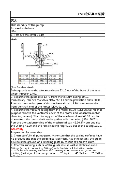
CVD液环真空泵拆装操英文Disassembly of the pumpProceed as follows:LEM:1. Remove the cover 16.10.2. With extractor, as shown, withdraw the vane wheel impeller from theshaft.(B = flat-bar steel)Subsequently take the tolerance sleeve 53.10 out of the bore of the vanewheel impeller 23.50.3. Separate the guide disc 13.70 from the vacuum casing 10.10.If necessary, remove the valve plate 75.11 and the protection plate 58.01. Remove the rotating part of the mechanical seal 43.30 by rotary motionfrom the shaft end of the motor (LEM. 91-251).4. Separate the vacuum casing from the motor 80.00 (LEM. 26/51: for that purpose remove the ventilator cover of the motor and loosen the motor clamping screws). The rotating part of the mechanical seal 43.30 can bedrawn from the motor shaft end together with the casing (LEM. 26/51). Remove the stationary ring of the mechanical seal 43.30, if worn out alsothe O-ring 41.20 and the radial sealing ring 42.10 out of the casing 10.10. AssemblyPreparation for assembly1. Clean carefully all pump parts. Make sure that the sealing surfaces haveno grooves and that the guide disc is perfectly flat. If necessary, the guidedisc must be ground on a levelling plate by means of abrasive cloth.2. Coat the running surface of the guide disc as well as all threads andfittings (except the sealing fittings) with Molykote lubrication paste.3. Provide the sealing surfaces with sealing compound shortly beforejointing (last sign of the pump code …0“: liquid …4“: Teflon …7“: Teflon/ O-ring)In general the liquid sealing compound Epple 33 is used for grey cast iron parts and Silastik for stainless steel parts.4. During assembly no foreign matter and no superfluous sealing compound must enter the pump.5. Use appropriate clamps/vices for clamping the parts for assembly Assembly of the pumpProceed as follows:(Pay attention to the sectional drawings!)LEM. 26 - 251:1. Insert radial seal ring 42.10 into the vacuumcasing 10.10. Press the stationary ring of themechanical seal 43.30 into the bore of the casing.2. Fasten the casing 10.10 to the motor 80.003. Slip the rotating parts of the mechanical seal 43.30 on the motor shaft end 80.00.4. Put the O-ring 41.20 into the groove. Connect the valve plate 75.11 and the protection plate 58.01 with the guide disc 13.70 (secure the screws, e.g. with Loctite 222) or put the valve balls 75.40 into the bores of the casing 10.10.5. Coat the sealing faces of the casing 10.10 with sealing liquid compound. Fasten the guide disc 13.70 to the vacuum casing 10.10. If necessary put on the spacer 52.50 to the motor shaft end.6. For fastening of the vane wheel impeller 23.50 and adjustment of front gap firstly it is necessary to tighten the guide disc 13.70 to the casing.7. Insert the key 94.01 (only LEM.161 and LEM.251)into the groove of the motor shaft. Now slip thevane wheel impeller 23.50, with the tolerancesleeve 53.10 inserted, on the motor shaft end80.00. Press the vane wheel impeller 23.50 on theshaft end until the required distance of the gapbetween vane wheel impeller 23.50 and guide disc13.70 will be achieved (see sketch).拆装操作指导书中文泵的拆卸进行如下工作:LEM:1.拆下盖16.10。
- 1、下载文档前请自行甄别文档内容的完整性,平台不提供额外的编辑、内容补充、找答案等附加服务。
- 2、"仅部分预览"的文档,不可在线预览部分如存在完整性等问题,可反馈申请退款(可完整预览的文档不适用该条件!)。
- 3、如文档侵犯您的权益,请联系客服反馈,我们会尽快为您处理(人工客服工作时间:9:00-18:30)。
液环式真空泵拆卸与装配步骤
液环式真空泵及压缩机是用来抽吸或压缩空气和其他无腐蚀性、不溶于水、不‘含有固体颗粒的气体,以便在密闭容器中形成真空和压力。
但吸人气体允许混有少量液体,它被广泛运用于机械、石油化工、制药、食品、制糖工业及电子领域。
液环式真空泵由于在工作过程中,气体的压缩是等温的,所以在压缩和抽吸易燃、易爆气体时,不易发生危险。
因此,耐腐蚀液下泵的应用更加广泛。
液环真空泵在拆卸时应注意哪些要点?今天小编来告诉你!
泵的拆卸分为部分拆卸检查并清洗和完全拆卸修理及更换零件,在拆泵前应将泵中的水从放水孔放出。
在拆卸时应将所有的垫片谨慎地取下,如发生损坏应在装配时更换同样厚度的新垫片。
泵应从不装有联轴器的一端开始拆卸,其顺序如下。
水环真空泵(简称水环泵)是一种粗真空泵,它所能获得的极限真空为2000~4000Pa,串联大气喷射器可达270~670Pa。
水环泵也可用作压缩机,称为水环式压缩机,是属于低压的压缩机,其压力范围为1~2×10Pa表压力。
水环泵最初用作自吸水泵,而后逐渐用于石油、化工、机械、矿山、轻工、医药及食品等许多工业部门。
在工业生产的许多工艺过程中,如真空过滤、真空引水、真空送料、真空蒸发、真空浓缩、真空回潮和真空脱气等,水环泵得到广泛的应用。
由于真空应用技术的飞跃发展,水环泵在粗真空获得方面一直被人们所重视。
由于水环泵中气体压缩是等温的,故可抽除易燃、易爆的气体,此外还可抽除含尘、含水的气体,因此,水环泵应用日益增多。
液环式真空泵拆卸与装配步骤
1、松开并取下轴承盖。
2、松开滚动轴承,先用钩扳手将圆螺母拧下,取下填料压盖上的螺帽。
3、由左侧盖的边将轴承架松开,同时转动两个拆卸螺钉(方头圆柱端螺钉),将轴承及轴承架从轴上取下。
4、使侧盖上的进水管和管子脱开并松开泵体与侧盖的连接螺钉和泵脚外的双头螺栓。
5、在泵体下加垫,然后使侧盖和泵体离开,从轴上取下侧盖(侧盖取下后应将轴支承住)。
6、使泵体与另一侧盖离开,并由轴上取下。
泵的部分拆卸至此为止,此时泵的工作部分及各个零件可进行检査及清洗,进一步的拆卸应按下列顺序继续进行。
7、切除电动机与电路的连接,松开电动机与底座连接,并与泵分开。
8、利用扳手等拆卸工具,自轴上取下联轴器。
9、从轴上取下联轴器的键。
10、取下轴承盖。
取下定位圈或取下圆螺母松开滚动轴承。