PR-3010微型一体化振动变送器
NEXON压力传感器选型手册

原理及特点通用参数应用■泵和压缩机■液压和气动■机床■机械制造■真空技术应用技术参数 (订货时用户可自定义量程)PN3010采用陶瓷厚膜传感器进行压力测量,信号由后部处理电路处理后转换成标准工业电信号输出并显示。
全金属外壳设计,采用高亮型LED 数字显示,使得该系列产品能够被用于各种工业场合。
双键设计和用户友好的菜单使产品使用更加方便。
多种连接方式可以充分满足各种特定的安装需求。
可330º旋转的显示头能保证在不同安装方式下获得最佳的观察角度。
·经济型产品·测量范围从0…1bar 到0…600bar ·4位LED 数字显示·全金属外壳·PNP/NPN 可设置·4...20mA/0…20mA 可设置;1…5V/0…5V 可设置·显示头可旋转N e x o n E l e c t r o n i c c a t a l o g P N 3010 c n v e r s i o n 1.0 2010 02设定面板窗口模式窗口模式下降过程中压力值要小于rP1时开关输出才释放。
窗口功能可使产品用来监视压力值是否超出一个特定的压力范围。
当压力值在rP1和SP1之间时,开关输出一种状态,而当压力值处于这个范围之外时开关输出另一种状态(与前一种相反)。
选型表i特殊要求可订制■用户指定的压力范围■G1/2, NPT1/2过程连接■食品卫生级法兰连接■用于粘性介质的齐平膜安装方式■加装用于高温介质的散热器■用户提出的其它电气,机械连接N e x o n E l e c t r o n i c c a t a l o g P N 3010 c n v e r s i o n 1.0 2010 02原理及特点通用参数应用■工程机械■液压和气动■机床■机械制造■泵和压缩机■石油钻探量程相关参数 (订货时用户可自定义量程)PN3020采用不锈钢薄膜传感器进行压力测量,信号由后部处理电路处理后转换成标准工业电信号输出并显示。
cpe 310-s 嵌入式多功能压力变送器 使用指南说明书
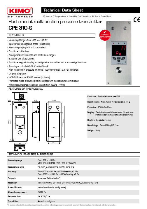
Flush-mount multifunction pressure transmitterCPE 310-SKEY POINTSFront face : Brushed stainless steel 316 LBack housing : Flush-mount in stainless steel 304 L Protection : IP65 in front faceDisplay : Electroluminescent alphanumeric (38 x 48 mm)Protection screen made of inactinic red PMMAHeight of the digits : 14 mm Back fittings : Barbed fitting Ø 5.2 mm Weight : 640 g- Measuring Ranges from -100 to +100 Pa 1- Input for interchangeable probe (Class 310)- Alternating display of 1 to 3 parameters - Front face calibration- Configurable intermediate and centre zero ranges - 3 audible and visual alarms- Front face keypad allowing to configure the transmitter and acknowledge the alarm - 3 analogue outputs 0-5/10 V or 0/4-20 mA- High resolution in pressure on model -100/+100 Pa (ex : 0.1 Pa) (optional)- Outputs diagnostic- MODBUS network RS485 system (optional)- Front face made of brushed stainless steel with electroluminescent displayFEA TURES OF THE HOUSINGTECHNICAL FEA TURES IN PRESSUREMeasuring range From -100 to +100 PaOther available range : from -1000 to +1000 Pa Measurement units Pa, mmH 2O, mbar, inWG, mmHG, daPa, hPa Accuracy*From -100 to +100 Pa : ±0.2% of reading ±0.8 Pa From -1000 to +1000 Pa : ±0.2% of reading ±2 Pa Zero drift None (see “Self-calibration”)Resolution 1 Pa, 0.1 mmH 2O, 0.01 mbar, 0.01 inWG, 0.01 mmHG, 0.1 daPa, 0.01 hPa Auto-calibration Manual or automatic (configurable)Allowed overpressure 25 000 Pa Response time 1/e (63%) 0.3 s Type of fluidAir and neutral gases234 m m92 mm44 mm 42.5 mm70 mm196 m m3.2218 m m76 mm69 mm147.3 m m *All accuracies indicated in this document were stated in laboratory conditions and can be guaranteed for measurements carried out in the same conditions, or carried out with calibration compensation.1Other measuring range available on request : from -1000 to +1000 PaPower supply 24 Vac / Vdc ±10 %Output3 x 0/4-20 mA or 3 x 0-5/10 V (4 wires)Maximum load : 500 Ohms (0/4-20 mA) / Minimum load : 1 K Ohms (0-5/10 V)Galvanic isolation On the output Consumption 5 WConformity CEM 2004/108/CE and NF EN 61010-1 directivesElectrical connection Screw terminal block for cables from 0.05 to 1.5 mm 2 or from 30 to 16 AWGRS485 communication Digital : Modbus RTU protocol, configurable communication speed from 2400 to 115200 Bauds (optional)Visual alarm Blinking of the value Audible alarmBuzzer (92 dB at 10 cm)Environment and type of fluid Air and neutral gasesOperating / storage temperaturesFrom -10 to +50 °C / From -10 to +70 °CTECHNICAL SPECIFICA TIONSSELF-CALIBRA TIONClass 300 transmitters have a temperature compensation system from 0 to 50°C and a self-calibration system to guarantee an excellent long-term stability, along with a great measurement accuracy.Self-calibration principle : the microprocessor of the transmitter drives a solenoid valve that compensates any long-term drifts of the sensitive element. The compensation is made by regular adjustment of the zero. The differential pressure measurement is then made regardless of the environmental conditions of the transmitter.INNOV A TIONSThe CPE310-S transmitter has a two adjustable pressure connections system in front face (A) coupled with two pressure connections at the back (B).When installing the transmitter, this system allows to configure the differential pressure connections with a set of plugs (supplied with the transmitter).➢Adjustable pressure connectionsThis system allows to isolate the back pressure connections and then to access the sensitive element (on the front face) of the pressure transmitter. Without dismantle the transmitter, this system allows to calibrate by connecting the transmitter to a pressure generator and acalibration bench. The calibration is easier and faster.➢Front face calibrationCONFIGURABLE ANALOGUE OUTPUTSConfigurable analogue outputs :Range with centre zero (-50/0/+50 Pa), with offset zero (-30/0/+70 Pa) or standard range (0/+100 Pa), it is possible to configure your own intermediate ranges. The minimum configurable range is 10% of the full scale.Configurable ranges according to your needs : outputs are automatically adjusted to the new measuring ranges+100-100+1000 V 4 mA 10 V 20 mA0050Newrange0 V 4 mA10 V 20 mA-100BSolenoid valve lifetime : 100 million cycles Advantage : no zero driftSelf-calibration frequency : can be disabled or set from 1 to 60 min➢Front face computer connectionMini-DIN connectionUSB connectionABlack-Red++-Red+Calibration bench24 Vac 12324 Vac ELECTRICAL CONNECTIONS – as per NFC15-100 standardThis connection must be made by a qualified technician. To make the connection, the transmitter must not be energized.24 Vdc power supply+➢For 24 Vdc power supply models :+Power supply terminal blockN ➢For 24 Vac power supply models :LPower supply terminal blockPe LN 230 Vac 24 Vac power supplyclass II~~or24 Vac power supplyN LPeL N230 VacN ➢Connection of the 0/4-20 mA current output :➢Connection of the 0-5/10 V voltage output :CONENCTIONSPressure connection +Pressure connection -A +B -Modbus :GND ALARMSThe CPE310-S pressure transmitter has 3 visual and audible alarms that are independent and configurable. Available settings are the followings : ●Time-delay duration : from 0 to 600 s ●Thresholds values ●Action of the alarm : rising edge, falling edge or monitoring ●Audible alarm activation (buzzer)INTEGRA TION OF PRESSURE MEASUREMENTThe pressure measurement element is very sensitive and reacts topressure changes. When making measurements in unstable air movement conditions, the pressure measurement may fluctuate. The integrationcoefficient (from 0 to 9) makes an average of the measurements ; this helps to avoid any excessive variations and guarantees a stable measurement.131415G N D – G r o u n d 0/4-20 m A –C u r r e n t 456OUT2G N D – G r o u n d 0/4-20 m A – C u r r e n t123OUT1NL ~~1230/4-20 m A – C u r r e n t G N D – G r o u n d 789OUT3-GND -mA +1 2 3+VRegulator display or PLC/BMS passive typeOUT1Regulator display or PLC/BMS passive type7 8 9OUT34 5 6Regulator display or PLC/BMS passive typeOUT27 8 9OUT34 5 61 2 3Regulator display or PLC/BMS passive typeOUT1Regulator display or PLC/BMS passive type+-+Regulator display or PLC/BMS passive type-For 24 Vdc powersupply models : -+orN e u t r a l (N )~P h a s e (L )~For 24 Vac power supply models :101112101112Power supply terminal block0-5/10 V – V o l t a g e0-5/10 V – V o l t a g e0-5/10 V – V o l t a g e101112--LGND mA VGND mA VGND mA VGND mA VGND mA VOUT2--++--+++-+-+-+-F T a n g _t r a n s m i t t e r _C P E 310-S – 20/12/13 – R C S (24) P ér i g u e u x 349 282 095 N o n -c o n t r a c t u a l d o c u m e n t – W e r e s e r v e t h e r i g h t t o m o d i f y t h e c h a r a c t e r i s t i c s o f o u r p r o d u c t s w i t h o u t p r i o r n o t i c e .MOUNTINGTo install a transmitter on a wall, make a cutting of 196 x 70 mm in the wall. Then drill 4 holes around the cutting as shown beside. Insert the transmitter into the wall and fix it with the 4 screws (supplied with the transmitter).MAINTENANCEAvoid aggressive solvents. When cleaning rooms or ducts with products containing formol, protect the the transmitter.OPTIONS●LCC-S : configuration software with USB cable ●RS5 : RS 485 Protocol Modbus digital output●HRP : high resolution (example in pressure : 0.1 Pa)●Calibration certificateCALIBRA TIONAdjusting and calibration on site : the professional configuration interface, with a dynamic pressure calibration bench, allows you to adjust and calibrate your transmitters directly on site or in laboratories.Outputs diagnostics : with this function, you can check with a multimeter (or on a regulator/display, or on a PLC/BMS) if the transmitter outputs work properly. The transmitter generates a voltage of 0 V, 5 V and 10 V or a current of 0 mA, 4 mA, 12 mA and 20 mACertificate : transmitters are supplied with an individual adjusting certificate and can be supplied with a calibration certificate as an option.RS 485 MODBUS PROTOCOLClass 310 transmitters can be linked in one network operating on a RS485 home bus.The RS 485 digital communication is a 2-wire network, on which the transmitters are connected in parallel. They are connected to a PLC/BMS via the RTU Modbus communication system. Since the CPE310-S can be configured with the keypad, the MODBUS enables remote configuration, to measure 1 or 2 parameters or to see the status of the alarms...CONFIGURA TIONClass 310 transmitters allows you to set all the parameters managed by the transmitter : units, measuring ranges, alarms, outputs, channels... via the different methods shown below : ➢Via keypad, only on models with display. A code-locking system for keypad guarantees the security of the installation. See configuration manual.➢Via software (optional) : simple and user-friendly. See LCC-S user manual.➢Via Modbus (optional) : configuration of all parameters from your PC, via the supervision or data acquisition software.INPUT FOR CLASS 310 INTERCHANGEABLE PROBESThe input for interchangeable probes allows to connect directly on CPE310-S transmitter, via the adaptor cable, an interchangeable probe of the class 310 range (see technical datasheet of probes for class310 transmitters).Advantage :the CPE310-S centralises, in addition of the pressure, temperature and humidity measurements of a SHDI150 probe for example.Adaptor connectionAdaptor for class 310 probes●Sliding fittings ●Connection fitting ●Clear tube●Pressure connections ●Trough-connectionsØ2.2mmCut-out depth =43mm70mm10m m196m m12m m3mm3mm。
PESD 3010 30kV 电静电解放生成器商品介绍说明书

PESD 301030kV Electrostatic Discharge GeneratorBringing dissimilar insulation materials together and then parting them creates electrostatic charges. The resultant electrostatic discharge (ESD) can cause failures in electronic circuits.There are two principal methods of discharge: Air discharge and contact discharge. Contact discharge is the preferred test method because test results are more reproducible.There are many standards which require discharge component (Resistor & Capacitor) values other than those described in the IEC/EN 61000-4-2 standard. With PESD 3010 it is possible to meet these requirements due to the changeable R&C modules.PESD 3010 features a unique NO CONTACT detection circuit. During contact discharge tests, PESD 3010 continuously monitors if ESD pulses are really discharged to the EUT (E quipment u nder T est). In case of no contact to the EUT, the operator receives a warning message in the LCD display. This prevents the user from potentially wrong test results.PESD 3010 has a highly ergonomic design. This includes a firm handle that insures safe and comfortable operation under any circumstances, and dedicated, large conventional pushbuttons for easy and convenient setting of all test parameters.For long running tests, a screw socket on the bottom enables to mount the gun on a standard tripod.IEC test levels L1 to L4 are predefined and are shown in the LCD together with thetest voltage.Capacitor modulesfor the PESD 3010 are available with any value in the range from 50pF to 1000pF and Resistor modules with any value in the range from 50 ohms to 5000 ohms, in any combination ensuring maximum flexibility. Features30kV Air discharge30kV Contact dischargeUser selectable R&C networksUnique integrated self test functionContact discharge current flow detectionRemote trigger inputSlow repetition rates for Automotive testingBenefitsFlexible System – PESD 3010 is a modular design that enables users to meet many different test specifications with maximum cost effectiveness. Efficiency and Reliability – The integrated self test function verifies all the relevant functions of the ESD generator at the push of a button within30 seconds.This ensures correct test of the device under test at any time, without doing time-consuming manual verifications of the ESD generator.Comfortable to use – The lightweight, balanced weight distribution and ergonomic handle design mean that testing can be performed over long periods without operators becoming fatigued.All actual test parameters are showed in a comfortable, large LCD.Sturdy and Reliable – Careful component selection ensures that the PESD 3010 will continue to operate under the most strenuous testing regime.ApplicationsIEC/EN 61000-4-2ISO/TR 10605 for Automotive TestingMIL 464 system requirementsMIL 331B Fuse & Fuse componentsMIL 1542B space system facilitiesMany more international product standardsl i s h e d1981Headquarters Haefely Test AGLehenmattstrasse 353 CH-4052, Basel Switzerland+ 41 61 373 41 11 + 41 61 373 45 99*********************Locate your local sales representative at North American OfficeHipotronics Inc. Haefely EMC Division1650 Route 22 Brewster, NY 10509++1 845 279 3644 x264++1 845 279 2467****************************Haefely has a policy of continuous product improvement. Therefore we reserve the right to change design and specification without notice.PESD3010_2006-05-23.docTechnical SpecificationsAir Discharge Voltage 1 – 30kV Voltage resolution 100 volt steps Cont. Discharge Volt. 1 – 30kV Discharge Polarity Positive & Negative Discharge Repetition Single/0.1/0.2/1/2/5/10/20 Hz Operating Modes Single & Continuous Discharge Counter1 - 9999Power Supply 85 – 264V 50/60Hz Default RC-Network 150 pF / 330 Ohm Power consumption30VAWeights and Dimensions (W x H x D, net weight) PESD 3010 Gun10 x 21 x 29 cm 1.5 kg PESD 3010 Controller 17 x 10 x 28 cm1.5 kgScope of Supply Art. No. 249963Qty. 1 PESD 3010 ESD Generator Qty. 1 Carrying caseQty. 1 Control and Power supply unit Qty. 1 Ground CableQty. 1 Test Finger Air dischargeQty. 1 Test Finger Contact discharge Qty. 1 Polarity moduleQty. 1 Capacitor module 150 pF IEC 61000-4-2 Qty. 1 Resistor module 330 Ohm IEC 61000-4-2 Qty. 1User ManualOptions & AccessoriesCapacitor Modules Available with any value in the rangefrom 50 to 1000pF. Fit in PESD 3010 rear panel. The Controller automati-cally shows the value in the LCD Resistor ModulesAvailable with any value in the range from 50 to 5000Ω. Fit in PESD 3010 rear panel. The system automatically shows the value in the LCD display VCPVertical Coupling Plane 0.5m x 0.5m, for indirect application of the ESD. Includes cable with 2 integrated 470 kOhm HV-ResistorsHCPHorizontal Coupling Plane 1.6m x 0.8m for indirect application of the ESD. Includes cable with 2 integrated 470 kOhm HV-ResistorsRemote Control Fibre optical RS 232 interface for remote control of ESD gunTest Table Made of wood without any metallic parts, as required by IEC 61000-4-2Verification SetFor wave shape verification according to IEC/EN 61000-4-2. Includes 2 Ohm Target, Attenuators, BNC Cable, user manualCapacitor, Resistor & Polarity ModulesESD Test Table with VCP & HCP。
罗斯蒙特 3051 压力变送器 产品说明书

产品说明书00813-0106-4001, Rev WE2023 年 4 月Rosemount™ 3051 压力变送器通过 Rosemount 3051 压力变送器,您将更有效地控制工厂,能够在众多压力、液位和流量应用中借助我们的产品,减少产品变化和复杂性,降低总拥有成本。
您将可以访问各种信息,方便您进行诊断、校正甚至防止出现问题。
以我们无与伦比的可靠性和丰富的经验打造的 Rosemount 3051 符合行业标准,可帮助您以更高的效率和安全性标准进行工作,从而保持全球竞争力。
Rosemount 30512023 年 4 月内容建立压力测量标准 (2)Rosemount 3051C 共平面压力变送器订购信息 (6)Rosemount 3051T 直连式变送器订购信息 (18)Rosemount 3051CF 流量计选择指南 (28)Rosemount 3051L 液位变送器订购信息 (62)技术规格 (74)Rosemount 3051 产品认证 (91)尺寸图 (92)选项外, (106)建立压力测量标准经实践检验的一流性能、可靠性和安全性■超千万装机量■参考精度为量程的 0.04%■安装总性能为量程的 0.14%■稳定性可保持在 URL 的 0.1% 长达 12 年■SIL 2/3 认证(IEC 61508)Coplanar ™平台增强安装和应用灵活性■通过集成的压差流量计、压差液位解决方案和一体化阀组提高可靠性和性能。
■安装方便,所有方案都全面组合,并经过渗漏测试和标定。
■丰富的产品满足您的应用需求。
高级功能Bluetooth ® 技术■提高生产力、可靠性和人员安全性。
无需高温作业许可。
无需攀爬储罐或建筑脚手架。
■快速组态、检修和排除故障,所有设备对技术人员触手可及,速度比传统 HART ® 连接快十倍。
诊断■回路完整性诊断将连续地监测电路,检测影响通讯信号的问题,并提供腐蚀、外罩进水或电源不稳定等警报。
湖北省计量测试技术研究院-CNAS认可项目
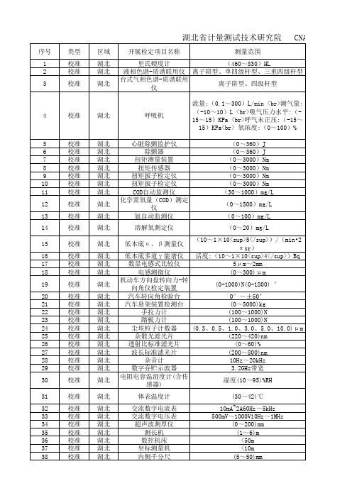
41 42 43 44 45 46 47 48 49 50 51 52 53 54 55 56 57 58 59 60 61 62 63 64 65 66 67 68 69 70 71 72 73 74 75
校准 校准 校准 校准 校准 校准 校准 校准 校准 校准 校准 校准 校准 校准 校准 校准 校准 校准 校准 校准 校准 校准 校准 校准 校准 校准 校准 校准 校准 校准 校准 校准 校准 校准 校准
87
校准
湖北
定碳定硫分析仪
88 89 90 91 92 93 94 95 96 97 98 99 100 101 102 103 104
校准 校准 校准 校准 校准 校准 校准 校准 校准 校准 校准 校准 校准 校准 校准 校准 校准
湖北 湖北 湖北 湖北 湖北 湖北 湖北 湖北 湖北 湖北 湖北 湖北 湖北 湖北 湖北 湖北 湖北
湖北省计量测试技术研究院
序号 1 2 3 类型 校准 校准 校准 区域 湖北 湖北 湖北 开展检定项目名称 测量范围
CNAS获准认可项
里氏硬度计 (460~830)HL 液相色谱-质谱联用仪 离子阱型、单四级杆型、三重四级杆型 台式气相色谱-质谱联用仪 离子阱型、四级杆型 流量:(0.1~300)L/min <br>潮气量: (-10~10)L <br>吸气压力水平:(15~15)KPa <br>呼气末正压:(-15~ 15)KPa<br> 氧浓度:(0~100)% (0~360)J (0~360)J (0~3000)Nm (0~3000)Nm (0~3000)Nm (0~3000)Nm (30~1000)mg/L (0~1500)mg/L (0~100)mg/L (0~20)mg/L (10~1×10<sup>5</sup>)/(min•2 π sr) 活度:(10~1×10<sup>4</sup>)Bq 5μ m~2mm (0~300)μ m
一体化振动变送器TS-V-33-5产品说明

一体化振动变送器TS-V-33/5产品说明一、简介随着DCS系统的普及,传统的二次表的功能基本都能由DCS系统实现,DCS系统只需要一个4~20mA的信号输入。
我公司研制改进型生产的两线制一体化机壳振动变送传感器能很好地满足这种要求,改进型具有体积小、质量轻、稳定可靠等多项优越的性能。
外壳均采用不锈钢壳体。
一体化振动变送器是利用磁电式振子运动切割磁力线原理将产生电压信号幅值转变成标准电流信号输出。
信号输出具有接错线保护功能。
避免现场误接线产生损坏变送器现象。
二、应用范围:机壳振动变送器广泛应用于电力、钢铁、石化等行业的风机、水泵、压缩机、汽轮机等旋转机械和其它设备测振。
设备运行时的各种振动量是估量设备运行是否正常的重要指标,应用DKS2240系列机壳振动变送器测振是一个经济、优质的方案。
机壳振动变送器系列全,根据选型可测量机壳振动速度和振动位移,用户可参照选型指南选用适合自己的产品。
机壳振动变送器有一款两线制,其完全按照《GB 3836.04-2000》设计生产,满足防爆场合的应用要求。
根据用户的需要,我们可以提供本安防爆认证。
三、技术指标量程:3. 1:振动速度量程0~100mm/s有效值;(可选)3. 2:振动位移量程0~1000μm峰峰值(测量类型及量程可按用户要求定制);3. 3:分辨率:0.05%;3. 4:温漂:≤ 0.1%/℃;3. 5:适用温度:(-20~ +80℃);3. 6:供电:+18~+35 V;3. 7:可承受最大冲击:2000g;3. 8:输出:4~20mA,1--5V ,1-10V 。
(可选)满量程时Vbuf为1Vp-p;3.9:负载:最大可以驱动500Ω负载;3.10:频响:10~1000Hz4.5~1000Hz (可按用户要求改变);3.11:横向灵敏度:<2%;3.12:外形尺寸:φ35×75mm3.13:重量:400g左右;3.14:外壳材料:不锈钢(可按用户要求改用其他材料)。
METTLER TOLEDO M300系列PH变送器

METTLER TOLEDOM300系列PH变送器1.简介M300 PH变送器是一台具有单测量通道的在线过程控制仪表,用于测量流体的PH值,它可以配合多种不同应用的梅特勒-托利多(METTER TOLEDO)传感器,并能够适应不同长度的连接电缆。
变送器具有同时显示数字和字符能力,带背光的大尺寸四行液晶显示器,可以同时显示测量数据和设置信息,简洁、灵活、清晰的菜单结够使您可以通过面板上的按键对变送器的各项操作参数进行设置,为了避免非法和末经授权的人员对设置进行修改,M300的菜单还设置了分级密码保护的菜单锁,M300变送器配置了两路模拟量输出和四路继电器触点输出,方便在过程控制系统中使用。
M300变送器还具有USB通讯接口和完备的控制指令,可以允许您通过个人电脑(PC)实时采集测量数据或对变送器进行远程监控和设置。
2.当心:本产品为四线制仪表,已使用有源4-20mA模拟输出,请勿向TB2 1~6引脚供电。
3.菜单机构Measurement modeMenu cal infoMenuQulck setupConfigureMeasurementChannel setupTemperaturePHSet averagingAnalog outputsSet poinsAlarm/cleanDisplayHold outputsSystemSet languageUSBPasswordSet/clear lockoutResetPID setupPID A/MTune parametersModePID display setupServiceDiagnostlcsMode/software revisionDigital inputDisplayKeypadMemorySet relaysRead relaysSet analog outputsRead analog outputsCallbrateTech serviceCallInfoMessagesCallbration dateMode/software revision4.操作按键5.菜单树的操作通过键,键,键,进入所需的主菜单。
上海敏泰 手持式仪表3010 说明书

使用说明书在开始操作此测量仪器前,请仔细阅读使用说明。
3160-00-67.00产品型号:智能传感器上海敏泰科技有限公司中国总代理:电话:021-68393909 传真:021-68393955地址:上海市浦东新区川沙工业园川大路699号( 201200)网址:手持式仪表30101.1 尺寸1.2 前言这本使用手册介绍了手持式测量仪表 Multi-Handy 3010。
这篇文档的所有内容进行了仔细的校对, 但不保证完全符合产品的所有参数。
Hydrotechnik 的责任是在产品销售和运输中单独列出有关清单。
使用本拷贝及涉及的其他相关文档和软件的内容需经过Hydrotechnik 公司的书面许可。
保留因技术进步而进行修改的权力. 感谢您的信任.你已经买了一台功能强大,最新的测量仪器,将给你日常的测量活动提供很好的支持。
你会很兴奋,不需要放大电路盒和其他需要连接的东西。
对于ISDS 仅仅连接传感器和多功能手持式测量仪器之间的电缆,你就可以开始第一次测量工作。
首先请仔细阅读使用手册。
收到此仪器后,请仔细检查仪器的外观状况,包括运输包装箱或包装袋及外部的损坏。
当仪器被再次运输时,也应该进行这种检查,还要按照清单进行完整性检查。
本使用手册包括了所有在操作仪器时要用到的内容。
如果你仔细阅读此手册,将有助于你更好地使用此仪器及延长仪器的使用寿命。
对你来讲使用Multi-Handy 3010 应该没有任何问题但如果你熟练掌握了仪器的操作方法,你会使用到它的全部功能。
在你遇到困难的时候,我们很乐意帮助你。
祝愿你成功学会使用 Multi-Handy 3010手持式测量仪表。
1. 使用手册 (1)1.1 尺寸...............................................................................................................................................................21.2 序言 ...............................................................................................................................................................21.3 关于Multi-Handy 3010的注释 ....................................................................................................................51.4 系统恢复.......................................................................................................................................................61.5 关于内部电池的注释.....................................................................................................................................61.6 装备...............................................................................................................................................................71.7..................................................................................................................................................71.8 (9)2. ............................ ............................................................................................2.1硬件技术参数 ..................................................................................................................................................102.2硬件描述. (10)2.2.1 .........................................................................................................................................................................102.2.2 ........................................................................................................................................................102.2.3 .............................................................................................................................................................102.2.4 ............................................................................................................................................................112.2.5 ....................................... .........................................................................................................................112.2.6 .................................................................................................................................................................112.2.7 ...................................................................................................................................................112.2.8 ..................................................................................................................................................................112.2.9 .........................................................................................................................................................112.2.10 . (12)3. ...............................................................................................................................................13 ............. ..................................................................................................................................13 (13).....................................................................................................................................14 . (14)...........................................................................................................................................................153.1 .......................................................................................................................................153.1.1............................................................................................................................................................153.1.2 ..................................................................................................................................................163.1.3........................................................................................................................................................163.1.4........................................................................................................................................................163.2 .............................................................................................................................................173.2.1 ..............................................................................................................................................................173.2.2.................................................................................................................................................173.3 ............................................................................................................................................173.3.1 ........... ......................................................................................................................................................173.3.2 .................................................................................................................................................................173.3.3 ..................................................................................................................................................................173.3.4 ..........................................................................................................................................................183.3.4a .................................................................................................................................................................183.3.5..........................................................................................................................................................183.3.6 .................................................................................................................................................................184. ..............................................................................................................................194.1 :.................................................................................................................................................194.2 :.. (19)主菜单测量显示时钟显示传感器检测电池联接操作菜单通过键盘操作安全注意事项说明内容仪器操作电源测量值存储峰值存储程序存储可能的连接方式Multi-Handy 3010.....................10通过功能键操作语言和对比度功能键测量通道菜单1-1测量通道菜单模拟测量通道1,2频率测量通道3测量计算通道4显示菜单2-1显示菜单通道选择和峰值定义存储菜单3-1存储菜单开始存储删除存储输入存储参数输入触发显示存储参数存储状态连接和PIN设置传感器连接通道1到2 模拟输出4.3 : ......................................................................................................................204.4RS232 / USB (20) (21) (21) (22)通道3频率输入 维护5.......................................................................................................................综述5.1.....................................................................................................质保期.......................................................................................................................6.......................................................1.3 关于Multi-Handy 3010的说明• 2,2“ 8 行显示• 通过键盘操作• 数字显示真实测量值• 通过不同触发调整存储测量值. 通过定义触发状态, 一个测量通道可被使用. • 通过RS232远程控制 (USB 适配器)• 通过 RS 232 (USB 适配器),可擦写flash- 存储器(操作程序) • 2 路模拟信号适用于电流信号为 0-20/4-20 mA 的传感器在内部,所有通道通过10 bit A/D - 转换工作• • • •最新式手持式仪表3010可以帮助用户出色地完成日常的测量任务。
3010报警控制器功能说明.
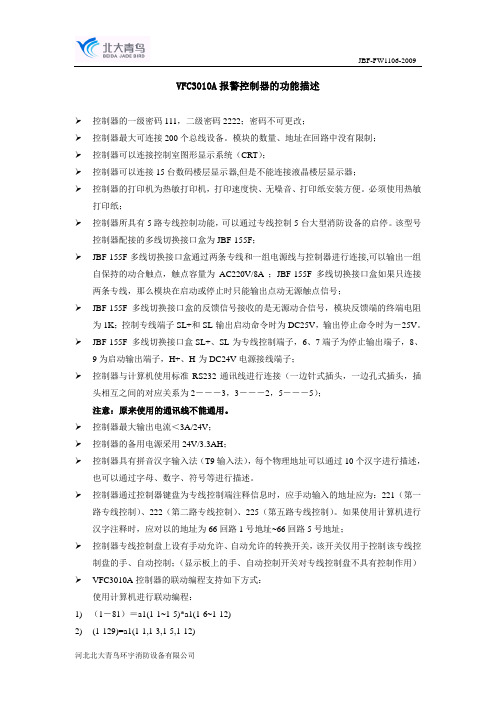
VFC3010A报警控制器的功能描述控制器的一级密码111,二级密码2222;密码不可更改;控制器最大可连接200个总线设备。
模块的数量、地址在回路中没有限制;控制器可以连接控制室图形显示系统(CRT);控制器可以连接15台数码楼层显示器,但是不能连接液晶楼层显示器;控制器的打印机为热敏打印机,打印速度快、无噪音、打印纸安装方便。
必须使用热敏打印纸;控制器所具有5路专线控制功能,可以通过专线控制5台大型消防设备的启停。
该型号控制器配接的多线切换接口盒为JBF-155F;JBF-155F多线切换接口盒通过两条专线和一组电源线与控制器进行连接,可以输出一组自保持的动合触点,触点容量为AC220V/8A ;JBF-155F多线切换接口盒如果只连接两条专线,那么模块在启动或停止时只能输出点动无源触点信号;JBF-155F多线切换接口盒的反馈信号接收的是无源动合信号,模块反馈端的终端电阻为1K;控制专线端子SL+和SL-输出启动命令时为DC25V,输出停止命令时为-25V。
JBF-155F 多线切换接口盒SL+、SL-为专线控制端子,6、7端子为停止输出端子,8、9为启动输出端子,H+、H-为DC24V电源接线端子;控制器与计算机使用标准RS232通讯线进行连接(一边针式插头,一边孔式插头,插头相互之间的对应关系为2―――3,3―――2,5―――5);注意:原来使用的通讯线不能通用。
控制器最大输出电流<3A/24V;控制器的备用电源采用24V/3.3AH;控制器具有拼音汉字输入法(T9输入法),每个物理地址可以通过10个汉字进行描述,也可以通过字母、数字、符号等进行描述。
控制器通过控制器键盘为专线控制端注释信息时,应手动输入的地址应为:221(第一路专线控制)、222(第二路专线控制)、225(第五路专线控制)。
如果使用计算机进行汉字注释时,应对以的地址为66回路1号地址~66回路5号地址;控制器专线控制盘上设有手动允许、自动允许的转换开关,该开关仅用于控制该专线控制盘的手、自动控制;(显示板上的手、自动控制开关对专线控制盘不具有控制作用) VFC3010A控制器的联动编程支持如下方式:使用计算机进行联动编程:1)(1-81)=a1(1-1~1-5)*a1(1-6~1-12)2)(1-129)=a1(1-1,1-3,1-5,1-12)3)(1-81,30,90)=a1(1-1,1-2,1-3,1-5)*a1(1-6,1-8,1-12)4)(1-81,3,6)=(1-5)+(1-12)使用控制器键盘进行编程:1)(81)=a1(1~5)*a1(6~12)2)(129)=a1(1,3,5,12)3)(81,30,90)=a1(1,2,3,5)*a1(6,8,12)4)(81,3,6)=(5)+(12)VFC3010A控制器专线控制的编程方法是:使用计算机进行联动编程:(66-1)=a2(1-1~1-12)(66-2,30,90)=(1-5)+(1-12)满足条件后延时30秒启动专线输出,保持90秒后撤销启动命令;(66-3)=a1(1-1~1-5)*a1(1-6~1-12)(66-4)=a1(1-1~1-4,1-6~1-12)*a1(1-5,1-20,1-23,1-25)使用控制器键盘进行编程:选择联动编程――选择多线联动关系――多线号延时时间(0默认值,立即启动不撤销)。
CPE 310 嵌入式多功能变送器操作手册说明书

操作手册C PE 310嵌入式多功能变送器0 / 4 ~ 20 m A - 电流相位 (L ) ~正端压力接头负端压力接头A +B -Modbus :GND 接地131415G N D - 接地456模拟输出2G N D - 接地0 / 4 ~ 20 m A - 电流123模拟输出10 / 4 ~ 20 m A - 电流G N D - 接地789模拟输出3用于电源供应24 Vdc 型号-+或中性 (N ) ~用于电源供应24 Vac 型号101112101112电源供应接线端口0 ~ 5 / 10 V - 电压0 ~ 5 / 10 V - 电压0 ~ 5 / 10 V - 电压电气接线 - 符合 NFC15-100 标准接线应由合格技术人员操作。
当接线时, 变送器必须停止供应电源。
24 Vac 12324 Vac 电源供应24 Vdc+➢电源供应 24 Vdc 接线方式:+电源供应接线端口N ➢电源供应 24 Vac 接线方式:L电源供应接线端口PeL N 230 Vac电源供应 24 Vac Class II ~~电源供应 24 VacN LPeL N 230 VacN ➢模拟输出信号 0 / 4 ~ 20 mA 接线方式:➢模拟输出信号 0 ~ 5 / 10 V 接线方式:N L~~123-GND-mA +1 2 3+显示仪或 PLC / BMS 主动种类通道1显示仪或 PLC / BMS 主动种类7 8 9通道34 5 6显示仪或 PLC / BMS 主动种类通道27 8 94 5 61 2 3+-+-101112--LGNDmA GNDmA GND VGND VGND V--++--+++-+-+-+-或通道1通道3通道2显示仪或 PLC / BMS 主动种类显示仪或 PLC / BMS 主动种类显示仪或 PLC / BMS 主动种类C PE 310-S 接线图内容目录1. 产品介绍 (5)1.1. 变送器介绍 (5)1.2. 按键介绍 (5)1.3. 温湿度传感器保护盖 (5)2. Modbus 通讯 (6)2.1. 设置参数 (6)2.2. 功能 (6)2.3. 寄存器读取码 (6)3. 进入不同功能 (9)4. F 100 : 设置变送器 (10)4.1. 序列号 : F100 (10)4.2. 固件版本 : F101 (10)4.3. 按键锁 : F 140 (10)4.4. 修改安全码 : F141 (10)4.5. 设置 Modbus 通讯 (适用于已订购此功能) (11)4.5.1 设置设备地址号码 : F150 (11)4.5.2 设置通讯速率 : F151 (11)4.6. 开启选购功能 (11)4.7. 恢复出厂设置 : F190 (12)5. F 200 : 设置通道和测量单位 (13)5.1. 开启通道 (13)5.2. 设置通道的测量单位 (13)6. F 300 : 管理模拟输出信号 (14)6.1. 设置模拟输出信号 (14)6.2. 设置模拟输出信号的对应量程 (14)6.3. 输出信号自诊断 (15)6.3.1 连接设置 (15)6.3.2 执行输出信号自诊断 (16)7. F400 : 设置报警 (17)8. F 500 : 设置测量功能 (20)8.1. 执行手动归零校准 (20)8.2. 差压测量稳定性积分系数 (20)8.3. 自动归零校准周期 (20)8.4. 输入校准系数值 (21)8.5. 输入校准补偿值 (21)9. 功能概括和 Modbus 通讯连接 (22)9.1. F 100 : 设置变送器 (22)9.2. F 200 : 设置通道和测量单位 (22)9.3. F 300 : 管理模拟输出信号 (22)9.4. F 400 : 管理报警 (23)9.5. F 500 : 设置测量功能 (24)1. 产品介绍1.1.变送器介绍CPE310 变送器可通过按键进行设置。
provibtech振动变送器说明书

provibtech振动变送器说明书PROVIBTECH派利斯TM016-151-120-00-1。
ProvibTech振动变送器TM016-01:铝导管弯头和减速器,NPT1"到3/4"。
ProvibTech振动变送器TM016-11:带接线端子的铝制导管弯头和减速器。
1"到3/4"NPTI,Div.1,B组,C&D;ClassII,Div.1,E,F&G组和NEMA4X,IP65。
ProvibTech振动变送器TM016-02:带接线端子的不锈钢导管弯头。
1"到3/4"NPTI,Div.1,A,B,C,D和T4组;ClassII,Div.1,E,F&G组和NEMA4X,IP65(与TM016配合使用)。
ProvibTech振动变送器TM016-03:不锈钢法兰安装适配器,带1/2"NPT安装;在直径为38mm(1.5英寸)的圆上有3个7mm的孔。
ProvibTech振动变送器TM0702-XX:铝制MIL连接器,带XX米电缆,直径6.35mm<120°C(250°F)。
ProvibTech振动变送器TM0703-XX:带XX米电缆的密封紧密套管连接器,直径6.35mm<120°C(250°F)。
ProvibTech振动变送器TM0704-XX:不锈钢MIL连接器,带铠装XX米电缆,直径4.83mm<150°C(300°F),比较大长度为10m。
ProvibTech振动变送器TM0705-XX:带有XX米电缆的CorneredMIL连接器,直径6.35mm<120°C(250°F),比较大长度为10m。
ProvibTech涡流传感器TM622-A00-B00-C00-D00-E00-G00。
ProvibTech涡流传感器TM621-A02-B00-C00-D00-E00-G00-10-M1:ProvibTech振动开关VS102-1100-3123。
一体化振动变送器的相关技术参数

一体化振动变送器的相关技术参数前言振动变送器是一种用于检测、监控和记录机器振动情况的设备。
振动变送器通常由传感器、变送器和终端设备三部分组成。
传感器用于测量振动,变送器将传感器测量到的振动信号转化为电信号,而终端设备用于显示、记录或处理振动信息。
在传统振动监测中,传感器和变送器通常是分离的,增加了系统的复杂性。
一体化振动变送器(Integrated Vibration Transmitter, IVT )包含传感器、变送器和信号处理电路,从而简化了系统设计,提高了稳定性和可靠性。
技术参数一体化振动变送器通常具有以下技术参数:1. 测量范围振动变送器的测量范围通常是以加速度为单位,并以G 表示。
常见的测量范围为05G 、020G 、050G 、0100G 等。
在实际应用中,应根据被测物体振动情况的特点和需求,选择合适的测量范围。
2. 频率范围振动变送器的频率范围通常是以赫兹为单位,并以Hz 表示。
常见的频率范围为010kHz 、01kHz 等。
需要注意的是,振动信号的频率与其特征有关,因此在选择振动变送器时应根据被测物体的振动频率范围来确定合适的振动变送器。
3. 精度振动变送器的精度通常与其测量范围和频率范围有关。
根据国际标准ISO10816规定,振动变送器的精度应满足以下要求:•测量范围为0~2G ,精度应在±0.2G 以内; •测量范围为2~100G ,精度应在±10%以内; •频率范围为5~1000Hz ,精度应在±5%以内; • 频率范围为1000~10000Hz ,精度应在±10%以内。
4. 输出信号振动变送器的输出信号通常是模拟电压信号或数字信号。
模拟电压信号一般为420mA 或010V ,数字信号一般为RS-485、Modbus 等接口。
5. 供电电压一体化振动变送器的供电电压通常为DC24V,也有一些型号支持AC100~240V 电源输入。
供电电压范围也是选择振动变送器时需要考虑的参数之一。
HMG 3010 高性能可移动测量和数据记录设备说明说明书

E 18.399.1/11.13Description:The HMG 3010 is an impressive, top performance portable measuring and data recording device.Automated setting procedures, a simple, self-explanatory operator guide and many comprehensive functions ensure the operator is able to carry out a wide range of measuring tasks within a very short time and to work in a way which is both time-saving and cost-effective. The HMG 3010 thus quickly becomes a reliable and helpful tool in the working environment of service, maintenance, development, test rig technology, quality assurance or commissioning of systems and machines.The HMG 3010 is designed primarily to record pressure, temperature and flow rate values which are the standard variables in hydraulics and pneumatics. For this purpose, special sensors are available, with which the variable, the measurement range and unit are automatically detected by the HMG 3010. The device also offers measurement inputs for standard sensors with current and voltage signals. In addition to the analogue inputs, the HMG 3010 also has two digital inputs (e.g. for frequency or rpm measurements).The ability to connect the HMG 3010 to a CAN bus and thus to displaymessages from the CAN bus completes the range of applications.Due to the wide range of functions and its simple handling, the HMG 3010 is just as appropriate for users who take measurements only occasionally as it is for professionals for whom measuring and documentation are routine. The update capability of theHMG 3010 via the integral USB port ensures that the user can benefit fromfuture upgrades of the device software.Special features:● Simple, user-friendly operation ● Practical, robust design● Large, full-graphics colour display ● Quick and independent basic setting of the device through the use of automatic sensor recognition● Up to 10 sensors can be connected simultaneously● Up to 32 measurement channels can be displayed at a time● Measuring rates up to 0.1 ms ● Extended voltage measurement -10 .. +10 V and 0 .. 50 V● Can be connected to a CAN bus● Very large data memory for archiving measurement curves ● Various measurement modes: – Normal measuring – Fast curve recording – Long term measuring ● 4 independent triggers, can be logically linked ● PC connection – USB – RS 232● Convenient visualisation, archiving and data processing using theHMGWIN 3000 and CMWIN software suppliedPortable Data RecorderHMG 3010E 18.399.1/11.13322Function:● Clear and graphical selection menus guide the operator very simply to all the device functions available. Anavigation pad on the keypad ensures rapid operation.● The HMG 3010 can monitor signals from up to ten sensors simultaneously . For this there are 5 robust standard input sockets. By using Y adapters, the number of inputs can be doubled individually to make a total of between 6 and 10.● Up to 8 sensors can be connected to 4 of these input sockets:- 8 sensors (e.g. for pressure, temperature, and flow rate) with the special digital HSI interface (HYDAC Sensor Interface); this means the basic devicesettings (measured variable, range, and unit of measurement) are undertaken automatically- 8 standard analogue sensors with current and voltage signals - 4 Condition Monitoring sensors*) (SMART sensors); again, thebasic device settings are carried out automatically● Frequency measurements, counter functions, or triggers for data logging can be implemented via the fifth input socket with 2 digital inputs.● For extended voltage measurement, the HMG 3010 offers the possibility of recording signals of0 .. 50 V on two inputs and a signal of -10 .. +10 V on one input (e.g. proportional valve control).● The connection to a CAN bus in conjunction with the CAN adapter ZBE 3010 makes it possible to record CAN messages (e.g. motor speed, motor oil pressure) in combination with measured data from the hydraulic system.● HYDAC CAN bus sensors connected directly to the CAN adapter can be parameterized using the HMG 3010 (node ID and baud rate)● All input channels canoperate simultaneously at ameasurement rate of 0.5 ms (1.0 ms for SMART sensors). To record highly dynamic processes, 2 analogue inputs are capable of recording measured values of 0.1 ms.● The most impressive function of the HMG 3010 is its ability to record dynamic processes "online", i.e. in real-time, as a measurement curve and to render them as graphs in the field.● The data memory for recordingcurves or logs can hold up to 500,000 measured values. At least 100 such full-length data records can be stored in an additional archive memory.● For specific, event-driven curves or logs, the HMG 3010 has four independent triggers, which can be linked together logically.● It is also possible to determinedifferential values between different input signals from sensors. Particularly when measuring flow rate by means of differential pressure measurement across a measuring orifice, theaccuracy can be significantly improved by using a stored calibration curve. To generate such calibration curves, the HMG 3010 has an easy-to-use handheld recording function.● User-specific device settings can be stored and re-loaded at any time as required. This means that repeat measurements can be carried out on a machine again and again using the same device settings.● Measured values, curves or texts are visualized on a full-graphics colour display in different selectable formats and display forms.● Numerous useful and easy-to-use auxiliary functions are available, e.g. zoom, ruler tool, differential value graph creation and individual scaling, which are particularly for use when analysing the recorded measurement curves.● The HMG 3010 communicates with a PC via the built-in USB port or RS 232port.E 18.399.1/11.13HMGWIN 3000:The PC software HMGWIN 3000 is also supplied with the device. This software is a convenient and simple package for analysing and archiving curves and logs which have been recorded using the HMG 3010, or for exporting the data for integration into other PC programs if required. It is also possible to operate the HMG 3010 directly from thecomputer, to undertake basic settings, and to start measurements online and display them directly on the PC screen as measurement curve progressions.CMWIN:The HYDAC software CMWIN is also supplied with the device. This software enables you tocommunicate directly with SMART sensors *) connected to the HMG 3010 from your PC.Both programs can be run onPCs with Windows Vista / XP / 2000 and Windows 7 operating systems.● Zoom function:Using the mouse, a frame is drawn around an interesting section of a measurement curve, which is then enlarged and displayed.Fig.: Zoomed section of measurement curve● Accurate measurement of the curves using the ruler tool (time values, amplitude values, and differentials)● Individual comments andmeasurement information can be inserted into the graph● Overlay of curves, for example todocument the wear of a machine (new condition/current condition)● Using mathematical operations(calculation functions, filter functions) new curves can be added.● Snap-shot function: comparable to the function of a digital camera, a picture can be taken immediately of any graph and saved as a jpg file.● A professional measurement report can be produced at the click of a mouse: HMGWIN 3000 has an automatic layout function.Starting with a table of contents, all recorded data, descriptions, and graphics and/or tables are combined into a professional report and saved as a pdf file.● Online function:Starting, recording, and online display of measurements (similar to the function of an oscilloscope)● Change of axis assignment of the recorded measurement parameters in graph mode (e.g. to producea p-Q graph )Some examples of the numerous useful additional functions:● Transfer and archiving ofmeasurements recorded using the HMG 3010● Display of the measurements in graph form or as a table*) SMART sensors(Condition Monitoring Sensors) are a generation of sensors from HYDAC which can provide a variety of different measured values.E 18.399.1/11.13324Technical data:Meas. inputs ● 4 input sockets (channels A-H) for connecting up to 8 analogue sensors or up to 4 SMART sensors. ● 1 input socket with 2 digital inputs (channels I-J) and one voltage input of -10 V to + 10 V (shown on channel H) Sensors are connected using standard M12x1 male connectors (5 pole)Channels A, B, E, F, G (Accuracy) HSI (≤ ± 0.1 % FS max.) 4 .. 20 mA (≤ ± 0.1 % FS max.) 0 .. 20 mA (≤ ± 0.1 % FS max.) 0 .. 4.5 V (≤ ± 0.1 % FS max.) 0 .. 5 V (≤ ± 0.2 % FS max.) 0 .. 10 V (≤ ± 0.1 % FS max.) 0.5 .. 4.5 V (≤ ± 0.1 % FS max.) 0.5 .. 5.5 V (≤ ± 0.2 % FS max.) 1 .. 5 V (≤ ± 0.2 % FS max.) 1 .. 6 V (≤ ± 0.2 % FS max.)Channels C and D HSI (≤ ± 0.1 % FS max.) (Accuracy) 4 .. 20 mA (≤ ± 0.1 % FS max.) 0 .. 20 mA (≤ ± 0.1 % FS max.) 0 .. 4.5 V (≤ ± 0.1 % FS max.) 0 .. 5 V (≤ ± 1.0 % FS max.) 0 .. 10 V (≤ ± 0.5 % FS max.) 0 .. 50 V (≤ ± 0.1 % FS max.) 0.5 .. 4.5 V (≤ ± 0.1 % FS max.) 0.5 .. 5.5 V (≤ ± 1.0 % FS max.) 1 .. 5 V (≤ ± 1.0 % FS max.) 1 .. 6 V (≤ ± 1.0 % FS max.)Channel H HSI (≤ ± 0.1 % FS max.) (Accuracy) 4 .. 20 mA (≤ ± 0.1 % FS max.) 0 .. 20 mA (≤ ± 0.1 % FS max.) 0 .. 4.5 V (≤ ± 0.1 % FS max.) 0 .. 5 V (≤ ± 0.2 % FS max.) 0 .. 10 V (≤ ± 0.1 % FS max.) 0.5 .. 4.5 V (≤ ± 0.1 % FS max.) 0.5 .. 5.5 V (≤ ± 0.2 % FS max.) 1 .. 5 V (≤ ± 0.2 % FS max.) 1 .. 6 V (≤ ± 0.2 % FS max.) -10 .. +10 V (≤ ± 0.5 % FS max.)Channels I and J Frequency range: 1 .. 30 000 Hz (Accuracy) (≤ ± 0.1 % FS max.) Switching / switch-back threshold: 2 V / 1 V Max. input voltage: 50 V Differential channels A - B C - D Difference channel for flow rate- measurement orifice (shown on channel B)Measuring rate 0.1 ms, max. 2 analogue input channels (dependent on 0.2 ms, max. 4 analogue input channels the number of 0.5 ms, all 10 input channels active channels) 1.0 ms, for SMART sensors Resolution 12 bit Memory At least. 100 measurement curves, each with up to 500,000 measured values Display 3.5" colour display Interfaces 1 USB, 1 serial port mark EN 61000-1/2/3/4Safety EN 61010Protection class IP 40Ambient Operating temp.: 0 .. +50 °C conditions Storage temp.: - 20 .. +60 °C Rel. humidity: 0 .. 70 %Weight 1100 g Note:FS (F ull S cale) = relative to the full measuring rangeMaterial No. 921238Additional accessories, such as electrical andmechanical connection adapters, power adapters, etc. can be found in the "Accessories - Service devices" catalogue sectionDimensions:shown with protective cover openE 18.399.1/11.13Pressure Transducer with HSITemperature Transducer with HSIHYDAC HSI sensors are part of a new plug and play, self-identify-ing sensor line. HSI sensors must be used with the HMG 500 and facilitate easy use with the HMG 3010. The HMG 3010 is capable of reading standard sensors as well as competitive models.Note:The information in this brochure relates to the operating conditions and applications described.For applications or operating conditions not described, please contact the relevant technical department. Subject to technical modifications.HYDAC ELECTRONICS90 Southland Dr. Bethlehem, PA 18017 Telephone +1 (610) 266-0100E-mail:************************Website: 。
K系列科里奥利流量计

(1) 标示的流量精度包括重复性、线性和滞后的综合影响。
标定代码 A ±0.2% 流量
气体测量的精度和重复性
性能规格 质量流量精度 (1) 质量流量重复性 (1) 温度精度 温度重复性
(1) 标示的流量精度包括重复性、线性和滞后的综合影响。
所有型号 ±1.0% 流量 ±0.5% 流量 ±1 °C ±0.5% 的测量值 (°C) ±0.2 °C
质量流量测量
测量管在力的作用下发生摆动,从而产生正弦波。流量为零时,两根管道同相地发生振动。有流量时,科里奥利力促使管道发生 弯曲,从而引发相偏移。这两个波形之间的相位差与质量流量成正比。
无流量
有流量
入口检测位移
出口检测位移 入口检测位移
出口检测位移
时间
时间
时差
密度测量
测量管以其固有频率振动。管道内介质质量的变化将导致管道固有频率发生相应的变化。通过管道的频率变化来计算密度。
通道 B (可组态)
一路有源频率 / 脉冲输出
非本安型 可以输出用于表明流量或总量的质量流量或体积流量 可调整至 10,000 Hz 电源:+24 VDC ±3% 12,500 Hz 内输出与流量呈线性
AF
8
一路有源 4–20 毫安输出
非本安型
与所有其他输出和接地线 ±50 VDC 隔离 最大负载限制:820 欧
2017 年 1 月
4
德科蒙过程控制(武汉)有限公司 QQ:113821586 TEL:15527360871 张工
2017 年 1 月
K 系列科里奥利质量流量计
液体流量
额定流量
高准公司采用的 “额定流量”术语是指在参考条件下水流引起的仪表压降约为 1 barg 时对应的流量。
ABB多参数变送器

现场总线单元(通讯码:P/F)
电源: 9~36VDC(带背光源指示器时 14~36VDC),反向极性保护,防爆变送器符合有
关的许可要求。
9 证书和许可(在有效期)
防爆,本安型“i” 标有(DIN EN 50014):EEx iaⅡCT6 与本安电路连接时的最大值:
对量程
0.05% / 0.1MPa
0.05% / 10MPa 0.05% / 10MPa
10/15-4.12
1) 对于钽、蒙乃尔、或镀金隔离膜片,静压和环境温度对精度的影响,可考虑因子为 1.5。
2) 量程比>1∶10 时
±(0.005×最大量程/调节量程-0.05)%
3) 量程 1kPa 时:
-20℃~+60℃
技术参数
10/15-4.12
最小报警电流: 3.5mA~4mA 可组态,标准设置:3.6mA
最大报警电流: 20mA~22.5mA 可组态,标准设置:21mA
标准设置:
最大报警电流
负载
4~20mA 变送器
R≤(Us – 10.5V)/ Imax kΩ Imax = 20~22.5mA 可组态 Us = 电源电压
6.2 环境条件 环境温度
-40℃~+85℃ 防爆变送器符合有关的许可要求。
贮存温度/运输温度
-50℃~+85℃,-40℃~ +85℃(带 LCD 指示器时)
湿度
相对湿度: 凝结、结冰:
防护等级
年平均≤95% 允许
IP 67
保护漆
环氧树脂,灰白,RAL 9002
抗冲击
加速度:
50g
持续时间:
抗震动
11ms
上海布朗电子科技有限公司
施达电子 SmartLine 系列压力变送器 STF700 產品說明書 说明书
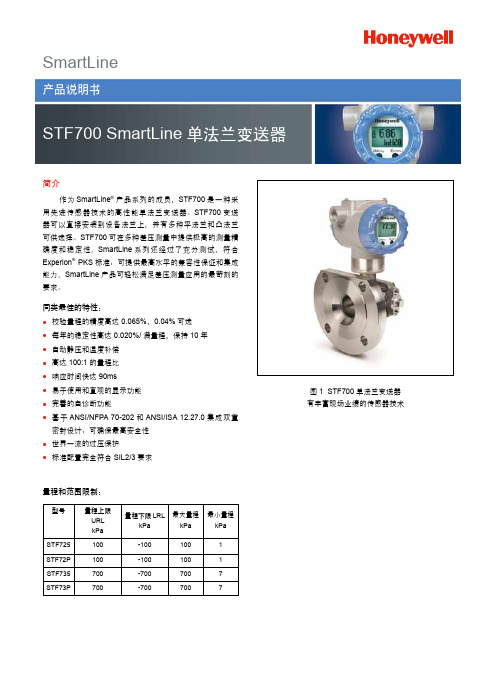
SmartLine简介作为SmartLine®产品系列的成员,STF700是一种采用先进传感器技术的高性能单法兰变送器。
STF700变送器可以直接安装到设备法兰上,并有多种平法兰和凸法兰可供选择。
STF700可在多种差压测量中提供极高的测量精确度和稳定性。
SmartLine系列还经过了充分测试,符合Experion® PKS标准,可提供最高水平的兼容性保证和集成能力。
SmartLine产品可轻松满足差压测量应用的最苛刻的要求。
同类最佳的特性:●校验量程的精度高达0.065%,0.04%可选●每年的稳定性高达0.020%/满量程,保持10年●自动静压和温度补偿●高达100:1的量程比●响应时间快达90ms●易于使用和直观的显示功能●完善的自诊断功能●基于ANSI/NFPA 70-202和ANSI/ISA 12.27.0集成双重密封设计,可确保最高安全性●世界一流的过压保护●标准配置完全符合SIL2/3要求量程和范围限制:型号量程上限URLkPa 量程下限LRLkPa最大量程kPa最小量程kPaSTF725 100-1001001 STF72P 100-1001001 STF735 700-7007007 STF73P700-7007007图1 STF700单法兰变送器有丰富现场业绩的传感器技术700说明SmartLine 系列压力变送器均基于高性能的传感器设计。
这一个传感器实际集成了多个传感器,将过程压力测量与静态压力(DP 型号)及用于温度补偿的温度测量相结合,从而实现了最佳的总体性能。
显示表头选项标准LCD 显示表头● 模块化(可以在现场增加或拆除)● 支持HART 协议● 0、90、180 和 270 度位置调整●测量单位包括:Pa 、kPa 、MPa 、KGcm2、T orr 、ATM 、 i4H 2O 、mH 2O 、bar 、mbar 、inH 2O 、inHG 、FTH 2O 、 mmH 2O 、mmHG 和psi 等测量单位● 大屏幕显示(高9.95mm x 宽4.20mm )2行,8个字符● 平方根输出指示和写保护提示●显示模块带有内部组态按钮,可通过内部或外部按键对变送器进行设置、调校自诊断功能SmartLine 变送器全部提供能以数字方式访问的诊断,这有助于提供可能的故障事件高级报警,从而最大限度缩减计划外停车,实现更低的整体工作成本。
CB3010

EMC 测试 抗噪声干扰测试符合 EN50082 第 1 和第 2 部分
抗振符合 IEC68-2-6 振幅 10-55Hz 时 1.5 mm 加速度 55-2000Hz 时 20 g
机械振动负载符合 IEC68-2-32 25 振动每 1 米高度
其它形式信息按要求或见订货细节
Data Sheet: D4-022
1
+信号
2
-电源/信号
3
+电源
〨
接地
G 1/2 Ø 27
安装和操作说明
安装位置对测量程序无影响。但是,建议保护变送器避免受到来自工作环境的各种影响(振动,温度,腐蚀等)。 调整零点的装置在壳体螺丝后部。可以穿过密封,通过拧松螺丝来调节电位计。
订货须知 -请给出未列型号的其他特性
压力变送器 -工业设计-
应用
压力变送器内部使用陶磁测量单元作为传感器。电气元 件把测量信号转换成一个标准的 4…20mA 的电流信号 (可选 0…20mA 或 0…10V)由于采用了耐用设计,它 普遍适用于各种工业环境,过程温度可达到 100℃。
设计及功能 电气元件密封以避免潮湿和振动。可以通过一个内置的 电位计来调节零点。电位计可以在外部通过拧松一个壳 体螺丝来调节。输出可以是 2 线或 3 线制的电路。压力 可以通过壳体顶部的一个开口和连接插头来补偿。
温度范围 过程温度-25…+100 ℃ 环境温度最高 50 ℃ 存放温度-40…+85 ℃ 允许环境温度-25…85 ℃ 温度补偿范围:-10…55 ℃
温度影响 对零点:≤0.25 % f.s./10 K 对测距:≤0.15 % f.s./10 K
辅助电源 标称电压 24 V DC 功能范围 11…40 V DC 最大允许额定测距 40 V DC 对于信号输出 0…10 V: 功能范围 14…40 V DC
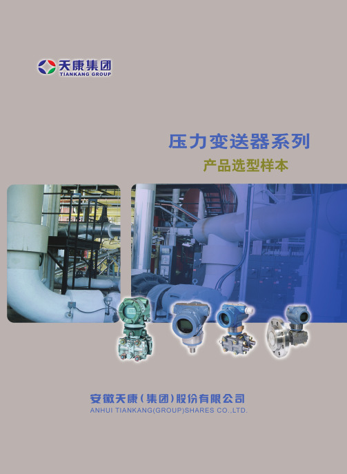
天康集团(压力变送器)选型样本
存贮器中。变送器掉电后,数据仍保存,故而上电后变送 器能立即工作。
数/模转换与信号传送 过程变量以数字式数据存贮,可以进行精确地修正和 工程单位的转换。信号经修正后的数据转换为模拟输出信 号。HART手操器可以直接以数据信号方式存取传感器读 数,不经过数/模转换以得到更高精度。
三、产品说明
传感膜头 3051C型采用先进技术及生产线制造的高品质传感 器。传感器与过程介质和外部环境保持机械、电气及热隔 离。传感器远离过程法兰,移至电子外壳的颈部,可实现 机械隔离和热隔离。该设计使传感器不与过程热源直接接 触,并释放了传感器杯体上的机械应力,可提高静压性 能。 玻璃密封的压力输送管与传感器杯体绝缘安装,保证 了电气绝缘,可提高电子线路的灵活性、性能与耐瞬变电 压保护的能力。 3051C型传感膜头还进行温度测量,用于补偿温度影 响。 在工厂的特性化过程中,所有传感器都经受了整个工 作范围内的压力与温度循环测试。根据由此得来的数据产 生修正系数,然后将系数贮存于传感膜头的内存中,从而 可保证变送器运行过程中能精确地进行信号修正。 该种传感膜头的内存也可帮助加快维修过程。因为所 有膜头的特性值都贮存在膜头中,所以可直接更换线路板 而无需重新校验或拆下独立的贮存。使用HART手操器可 以方便地对3051型进行组态。组态由两部分组成。首先, 设定变送器的工作参数,包括:存修正系数的PROM。 传感膜头内还有线路板,它将输入的电容与温度信号 直接转换成可供电子板模块进一步处理的数字化信号。
1
ANHUI TIANKANG(GROUP)SHARES CO.,LTD.
3051L型液位变送器 液位测量精度达0.1% 校验量程从0.4kPa至2.1MPa 平膜片式,2-,4-,与6英寸伸出式膜片 多种灌充液可选,可满足不同应用场合要求 小巧而质轻,易于安装与维护 接液件材料:不锈钢,哈氏合金和钽
Easidew PRO XP 露点变送器 用户手册说明书
Michell Instruments
v
附录
附录 A 附录 B
附录 C
附录 D 附录 E
Easidew PRO XP用户手册
技术条件.............................................................26
危险区域认证.........................................................28
3 操作....................................................................20 3.1 测量和配置...............................................................20 3.2 取样提示.................................................................21
Easidew PRO XP
有关Michell Instruments的联系信息,请访问
© 2022 Michell Instruments 本文件是Michell Instruments有限公司的财产,未经Michell Instruments有限公司的明确书面授 权,不得复制或以其他方式复制、以任何方式传达给第三方,也不得存储在任何数据处理系统中
缩写 .............................................................................. viii
1 介绍.....................................................................1 1.1 特色......................................................................1
- 1、下载文档前请自行甄别文档内容的完整性,平台不提供额外的编辑、内容补充、找答案等附加服务。
- 2、"仅部分预览"的文档,不可在线预览部分如存在完整性等问题,可反馈申请退款(可完整预览的文档不适用该条件!)。
- 3、如文档侵犯您的权益,请联系客服反馈,我们会尽快为您处理(人工客服工作时间:9:00-18:30)。
PR-3010微型一体化振动变送器
上海航振仪器仪表有限公司的PR-3010是在压电式加速度传感器的基础上,增加了内置精密积分电路,实现速度量输出。
具有比磁电式速度传感器响应频率范围宽大(2HZ-4000HZ)、机械运动部件不易损坏(使用寿命达7年)、传感器质量小、动态特性优良等优点。
变送器相应于测量值提供4-20mA的电流输出,本产品有接线容错保护,具有优良的稳定性、可靠性及很强的抗干扰能力。
普林斯顿一体化振动速度传感器概述:
PR-3010是在压电式加速度传感器的基础上,增加了内置精密积分电路,实现速度量输出。
具有比磁电式速度传感器响应频率范围宽大(2HZ-4000HZ)、机械运动部件不易损坏(使用寿命达7年)、传感器质量小、动态特性优良等优点。
变送器相应于测量值提供4-20mA的电流输出,本产品有接线容错保护,具有优良的稳定性、可靠性及很强的抗干扰能力。
一)主要技术参数:
1,测量范围:振动速度0-200mm/s(可选),常规为0-20mm/s;测量加速度0-50g(可选)2,输出电流:4--20mA
3,响应频率:2HZ-4000HZ
4,速度方向:从底部到传感器(正向)
5,环境温度:-10℃--+70℃
6,供电电压:12V--36V
7,壳体材料:不锈钢
8,重量: 110克
9,安装螺纹:M5,M10*1.5螺纹或磁吸座。
(或特殊定做)
10,压电材料:PZT-5
11,输出方式:两线制
12,附件:
一,合格证标定参数
二,安装螺钉一只
三,航空插头电缆一根(标配2米)
四、选型手册PR-3010-A□□-B□□-C□□-D□□-E□□
A□□ 测量类型
0 1 速度量(mm/s)0 2 加速度量(g)0 3 位移量(μm) B□□量程范围。
