合金电阻规格书
LR2728-24R040F1系列规格书贴片合金电阻推荐

EX: R001 = 1mΩ R010 = 10mΩ R100 = 100mΩ R00025 = 0.25mΩ
D=± 0.5% F=± 1.0% G=± 2.0% J=± 5.0%
A=500pcs 1=1,000pcs 2=2,000pcs 4=4,000pcs
制訂
IE 審查
核准
QA 會簽
Sales 會簽
0.085±0.010 (2.159±0.254)
0.071±0.010 (1.803±0.254) 0.065±0.010 (1.651±0.254) 0.051±0.010 (1.295±0.254) 0.045±0.010 (1.143±0.254)
0.5
LR4527S (without heat sink)
2512 -
2
1
R001
F
4
型別 金屬板微電阻
尺寸
端子數
額定功率
電阻值
容差
包裝數量
● 1206 ● 2010 ● 2512 ● 2725 ● 2728 ● 4527 ● 4527S
2:2 個端電極
● C=0.5W ● 1=1.0W ● A=1.5W ● 2=2.0W ● 3=3.0W ● B=3.5W ● 4=4.0W ● 5=5.0W
4.1 ~100.0
(0.645±0.254) (0.787±0.254)
0.3
0.040±0.010 0.079±0.010 (1.000±0.254) (2.02±0.254)
1.0 & 1.5
0.5 ~ 3.0 3.1 ~ 4.0
0.031±0.010 0.074±0.010 (0.787±0.254) (1.880±0.254)
LR1206-21R050F4系列规格书贴片合金电阻推荐

0.074±0.010 (1.880±0.254) 0.044±0.010 (1.118±0.254) 0.079±0.010 (2.02±0.254) 0.074±0.010 (1.880±0.254) 0.044±0.010 (1.118±0.254) 0.066±0.010 (1.676±0.254) 0.044±0.010 (1.118±0.254) 0.085±0.010 (2.159±0.254) 0.071±0.010 (1.803±0.254)
自行注意版本更新
註
非經允許,禁止自行影印文件
60 Series No.
RALEC
旺詮
LR 金屬板微電阻規格標準書
4 尺寸及構造
1206 / 2010 / 2512 / 2725 / 2728
L
文件編號 版本日期 頁次
IE-SP-060 2015/07/01
4/19
4527 / 4527S
L
W H
T1
T2
0.038±0.010 (0.965±0.254) 0.038±0.010 (0.965±0.254)
備
非發行管制文件
發行管制章 DATA Center.
自行注意版本更新
註
非經允許,禁止自行影印文件
60 Series No.
RALEC
旺詮
LR 金屬板微電阻規格標準書
文件編號 版本日期 頁次
4.1 合金板材料:
7.0~50.0 --
7.0~49 7.0~50
0.3~50.0 0.3~1.0 0.5~100 0.3~100
LR2512
0.3mΩ: ≦±150
2512 0.004R 合金电阻_顺海科技

2512 0.004R合金电阻
2512 0.004R 合金电阻指的是合金电阻的尺寸与阻值参数,这类合金电阻一般是一锰铜合金与铁铬铝合金和康铜合金为主,具有高可靠性与防腐蚀性等特点,主要应用在电池保护板中,起到电流检测作用,如平衡车就会用到2512 0.004R与2512 0.007R两个参数的合金电阻,但是根据不同的方案,电阻的阻值也会有所不同,顺海科技是一家专业代理销售合金电阻,低阻值电阻的通路公司,海量库存,价格优势,更多参数与型号请咨询相关业务。
2512 0.004R 合金电阻有哪些型号与参数呢?
从合金材料来区分,主要是有锰铜合金与铁铬铝合金,也有部分康铜合金。
2512 0.004R 合金电阻,按照功率可以分为2W余3W。
2512 0.004R 合金电阻,按照精度可以分为0.5%余1%。
合金电阻的料号与参数如下:
MSH2512M2W0R004F 2512 0.004R 2W 1% 50ppm/℃最小包装:4000PCS/盘
MSH2512M3W0R004F 2512 0.004R 3W 1% 50ppm/℃最小包装:4000PCS/盘
MA251220FR004FZ 2512 0.004R 2W 1% 50ppm/℃最小包装:4000PCS/盘
MA251230FR004FZ 2512 0.004R 3W 1% 50ppm/℃最小包装:4000PCS/盘
LR2512-22R004F4 2512 0.004R 2W 1% 50ppm/℃最小包装:4000PCS/盘
LR2512-23R004F4 2512 0.004R 3W 1% 50ppm/℃最小包装:4000PCS/盘。
2512 0.002R 合金电阻

2512 0.002R 合金电阻
2512 0.002R合金电阻是合金电阻中非常常规的参数,主要应用于电源设备,工业自动化,电池保护板等等电流检测电路中。
2512 0.002R合金电阻的含义:
2512指的是合金电阻的尺寸,合金电阻也有其他的尺寸,如1206等等。
0.002R指的是合金电阻的阻值,0.002R=2mR也叫2毫欧,因此也有人称为毫欧电阻。
2512 0.002R合金电阻主要有以下几个参数:
2512 0.002R 2W 1%
2512 0.002R 3W 1%
2512 0.002R 2W 0.5%
2512 0.002R 3W 0.5%
2512 0.002R合金电阻的品牌也非常多,如华德,天二,光颉,国巨,松下,威世等等。
顺海科技代理华德全系列产品,主要有保险丝、贴片式保险丝、微型保险丝、超小型保险丝、陶瓷管保险丝、玻璃管保险丝、温度保险丝、保险丝座与配件、合金电阻等等。
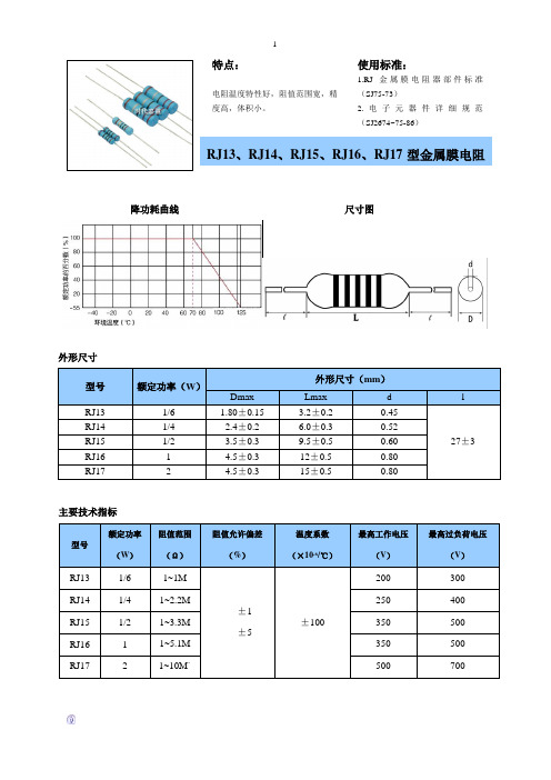
RJ系类金属膜电阻器规格书
可焊性
焊料能自由流动并与引线润湿
235±5℃ 2±0.5s
耐焊接电
△R≤(0.5%R+0.05Ω )
260±5℃ 10±1s
过载 温度快速变化
△R≤(0.5%R+0.05Ω ) △R≤(0.5%R+0.05Ω )
2.5 VR 5S -55℃/+125℃ 5 次循环
振动
△R≤(0.5%R+0.05Ω )
10~500Hz 98/s²
长期负荷 稳态湿热
△R≤(2%R+0.05Ω ) △R≤(2%R+0.05Ω )
+70±2℃ VR 1000h +40±2℃ 温度 95~3% 240h
额定功率(W)
1/6 1/4 1/2 1 2
Dmax 1.80±0.15
2.4±0.2 3.5±0.3 4.5±0.3 4.5±0.3
外形尺寸(mm)
Lmax
d
3.2±0.2
0.45
6.0±0.3
0.52
9.5±0.5
0.60
12±0.5
0.80
15±0.5
0.80
l 27±3
主要技术指标
型号
额定功率 阻值范围
2
主要检验项目、试验方法及性能要求
检验项目
性能要求
试验方法
电阻温度系数
≥±100×10-6 /℃
-55℃/+20℃ 20℃/+125℃
引出端强度
R≤(0.5%R+0.05Ω )
拉力 5N 或 10N 弯曲连续两次
耐电压
无击穿或飞弧
V 形块法,施加交流电压,其峰值为绝缘电压的 1.42 倍,1min
台湾天二大阻值合金采样电阻TGL系列选型规格书
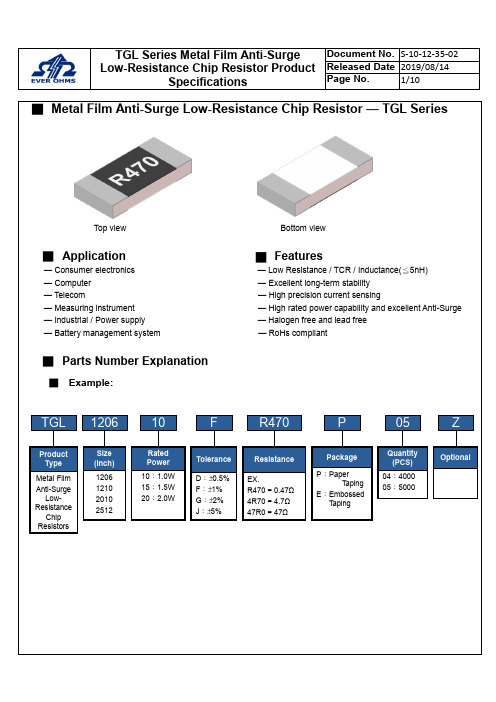
■Metal Film Anti-Surge Low-Resistance Chip Resistor — TGL SeriesTop view Bottom view■Application█Features— Consumer electronics — Low Resistance / TCR / Inductance(≦5nH)— Computer — Excellent long-term stability— Telecom — High precision current sensing— Measuring instrument — High rated power capability and excellent Anti-Surge — Industrial / Power supply — Halogen free and lead free— Battery management system — RoHs compliant■Parts Number Explanation■Example:Final Milestone DateCheckpointTGL1206F R470P05Size (Inch) 1206 1210 2010 2512ToleranceD:±0.5%F:±1%G:±2%J:±5%PackageP:PaperT apingE:EmbossedT apingQuantity(PCS)04:400005:5000ZOptionalProductTypeMetal Film Anti-SurgeLow-ResistanceChip ResistorsResistanceEX.R470=0.47Ω4R70=4.7Ω47R0=47Ω10RatedPower10:1.0W15:1.5W20:2.0W■Standard Electrical SpecificationsType RatedPowerat 70℃Max.RatedCurrentMax.OverloadCurrentT.C.R.(ppm/℃)Resistance RangeD(0.5%), F(1.0%), G(2.0%), J(5.0%)TGL1206 1W 3.16A 7.07A±50 100 mΩ ≦R ≦50 ΩTGL1210 1W 3.16A 7.07ATGL2010 1.5W 3.87A 8.66A±50 100 mΩ ≦R ≦50 ΩTGL2512 2W 4.47A 10.00A● For non-standard parts, please contact our sales dept.● Operating Temperature Range :−55℃〜+155℃.■Anti-Surge Ability:■Type Dimension■Construction Unit:mmTYPE L W H I1I2 TGL1206 3.10±0.10 1.60±0.10 0.55±0.10 0.40±0.20 0.45±0.20 TGL1210 3.10±0.10 2.50±0.15 0.55±0.10 0.50±0.20 0.50±0.20 TGL2010 5.00±0.20 2.50±0.15 0.55±0.10 0.60±0.25 0.60±0.25 TGL2512 6.30±0.20 3.20±0.20 0.55±0.10 0.65±0.25 0.65±0.25①Alumina Substrate ⑥Top Protective Overcoat②Resistive Layer ⑦Marking③Bottom Inner Electrode (Cu) ⑧Side Inner Electrode④Top Inner Electrode ⑨Barrier Layer (Ni)⑤Bottom Protective OvercoatWhite⑩Solder coating (Sn)■ Perfo r mance CharacteristicsPower Derating Curve ■The Operating Temperature Range: -55°C ~+155°C.Power rating or current rating is in the case based on continuous full-load at ambient temperature of 70℃. For operation at ambient temperature in excess of 70℃, the load should be derated in accordance with figure of derating Curve.■ Rated CurrentResistance Range: ≦ 1ΩRated Current: The resistor shall have a DC continuous working current or a AC (rms) continuous working current at commercial-line frequency and wave form corresponding to the power rating, as determined formula as following:I = Rated current (A) P= Rated Power (W) R= Resistance(Ω)■ Rated VoltageResistance Range: > 1ΩRated Voltage: The resistor shall have a DC continuous working voltage or a RMS AC continuous working voltage at commercial-line frequency and wave form corresponding to the power rating, as determined formula as following:V = Rated voltage (V)V = √P ×R P = Rated power (W)R = Nominal resistance (Ω)-5520406080100020406080100120140155℃Ambient Temperature (℃)Power Ratio(%)DERATING CURVE70160■Reliability Test and RequirementTest Item Test Method Procedure Requirements TemperatureCoefficient of Resistance(T.C.R) JIS C 5201-1clause 4.8TCR +125 ℃, 25 ℃is the reference temperatureRefer to StandardElectrical SpecificationsShort Time Overload JIS C 5201-1clause 4.135 times rated power for 5 seconds. ±(1.0%+0.001Ω)Insulation Resistance JIS C 5201-1clause 4.6100V for 1 minute. ≧10GΩDielectric Withstanding Voltage JIS-C5201-1clause 4.71206、1210、2010、2512 for 500 VAC 1minNo short or burned on theappearance.Core Body Strength JIS-C5201-1clause 4.15Central part pressurizing force:10N , 10 seconds No brokenSolderability JIS C 5201-1clause 4.17245±5°C for 3±0.5secs.>95% CoverageNo Visual damageResistance to Soldering Heat JIS-C5201-1clause 4.181. Molten solder, 260±5 °C,10±1 seconds immersion time2. IR reflow, refer to solder reflow temperature condition±(1.0%+0.001Ω)No Visual damageLeaching JIS-C5201-1clause 4.18260±5℃for 30 seconds.>95% CoverageNo Visual damageTemperature Cycling JIS C 5201-1clause 4.19-55℃to +155℃, 300 cycles±(1.0%+0.001Ω)No Visual damageLoad Life in Humidity JIS C 5201-1clause 4.2440±2℃, 90~95% R.H. , Rated power or Max. workingcurrent whichever is less for 1000 hrs with 1.5 hrs〝ON〞and 0.5 hr〝OFF〞.±(1.0%+0.001Ω)Load Life (Endurance) JIS C 5201-1clause 4.2570±2℃, Rated power, or Max. working current whichever isless for 1000 hrs with 1.5 hrs〝ON〞and 0.5 hr〝OFF〞.±(1.0%+0.001Ω)High Temperature Exposure JIS C 5201-1clause 4.25155±5℃for 1000 +48/-0 hours. ±(1.0%+0.001Ω)Resistance to Solvent JIS C 5201-1clause 4.29The tested resistor be immersed into isopropyl alcohol of20~25℃for 60 secs.Then the resistor is left in the room for 48 hrs.±(1.0%+0.001Ω)No Visual damageTerminal Strength JIS-C5201-1clause 4.32Pressurizing force for 10 seconds1206 and above:17.7NNo brokenTerminal Bending Strength JIS C 5201-1clause 4.33Bending once for 5 secondsD:1206、1210 = 3mm2010、2512 = 2mm±(1.0%+0.001Ω)No Visual damage● Temperature Coefficient of Resistance test to - 55 ℃is available on request■MarkingSolder reflow Temperature condition■Appendix For SMD Chip ResistorSIZE A ΦB ΦC■Packaging Information■Tapping SpecificationUnit: mm Packaging Type A B W E F G H T ΦD PPaper Type1206 1.90±0.2 3.05±0.28.0±0.2 1.75±0.1 3.5±0.05 4.0±0.1 2.0±0.050.75±0.1 4.0±0.11210 2.85±0.2 3.05±0.28.0±0.2 1.75±0.1 3.5±0.05 4.0±0.1 2.0±0.050.75±0.1 4.0±0.1■Embossed DimensionUnit: mm Packaging Type A B W E F G H T ΦDΦD1T1 PEmbossedType 2010 2.80±0.25.60±0.212±0.1 1.75±0.15.5±0.05 4.0±0.1 2.0±0.050.23±0.1 1.50±0.10.85±0.15 4.0±0.1 2512 3.40±0.2 6.70±0.212±0.1 1.75±0.15.5±0.05 4.0±0.1 2.0±0.050.23±0.1 1.50±0.10.85±0.15 4.0±0.1PaperCarrier■ Packing Material Data / Storage Data■ Front & Back Lead Dimension■ Top Adhesive Peel Off Strength :10~70g■ PackageInner Box Size Reel Size H(mm) 1 13 2 24 3 36 5 60 10113■ Storage Data :Storage time at the environment temp: 25±5℃& humidity: 60±20% is valid for one year from the date of delivery. External Box SizeContain (Kpcs) Length (mm)Width (mm)Width (mm)25K 180 180 60 50K 180 180 110 150K 430 200 200 300K400400200。
合金贴片电阻规格表
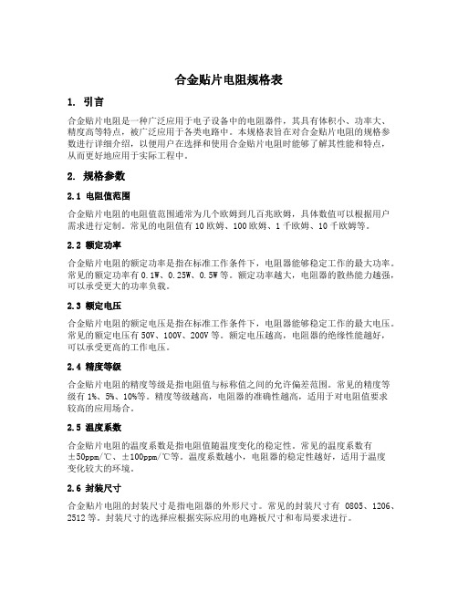
合金贴片电阻规格表1. 引言合金贴片电阻是一种广泛应用于电子设备中的电阻器件,其具有体积小、功率大、精度高等特点,被广泛应用于各类电路中。
本规格表旨在对合金贴片电阻的规格参数进行详细介绍,以便用户在选择和使用合金贴片电阻时能够了解其性能和特点,从而更好地应用于实际工程中。
2. 规格参数2.1 电阻值范围合金贴片电阻的电阻值范围通常为几个欧姆到几百兆欧姆,具体数值可以根据用户需求进行定制。
常见的电阻值有10欧姆、100欧姆、1千欧姆、10千欧姆等。
2.2 额定功率合金贴片电阻的额定功率是指在标准工作条件下,电阻器能够稳定工作的最大功率。
常见的额定功率有0.1W、0.25W、0.5W等。
额定功率越大,电阻器的散热能力越强,可以承受更大的功率负载。
2.3 额定电压合金贴片电阻的额定电压是指在标准工作条件下,电阻器能够稳定工作的最大电压。
常见的额定电压有50V、100V、200V等。
额定电压越高,电阻器的绝缘性能越好,可以承受更高的工作电压。
2.4 精度等级合金贴片电阻的精度等级是指电阻值与标称值之间的允许偏差范围。
常见的精度等级有1%、5%、10%等。
精度等级越高,电阻器的准确性越高,适用于对电阻值要求较高的应用场合。
2.5 温度系数合金贴片电阻的温度系数是指电阻值随温度变化的稳定性。
常见的温度系数有±50ppm/℃、±100ppm/℃等。
温度系数越小,电阻器的稳定性越好,适用于温度变化较大的环境。
2.6 封装尺寸合金贴片电阻的封装尺寸是指电阻器的外形尺寸。
常见的封装尺寸有0805、1206、2512等。
封装尺寸的选择应根据实际应用的电路板尺寸和布局要求进行。
3. 性能特点3.1 体积小合金贴片电阻采用贴片封装,相比传统的插件电阻体积更小,可以大大节省电路板空间,提高电路布局的灵活性。
3.2 功率大合金贴片电阻采用高功率陶瓷基底和合金电阻材料,具有较高的功率承载能力,能够满足一些功率要求较高的应用场合。
贴片合金电阻 2512 0.011R_顺海科技

贴片合金电阻 2512 0.011R
2512 0.011R合金电阻是一款非常冷门的贴片合金电阻,这个产品很少会有现货,另外就是不分厂商也不会生产这个阻值,很多都会选择0.01R或者0.012R两款阻值。
2512 0.011R的合金电阻主要有以下几种参数和材质说明:
2512 0.011R 2W 1% 50ppm/℃铁铬铝合金/康铜合金/镍铬合金/锰铜陶瓷合金
2512 0.011R 3W 1% 50ppm/℃铁铬铝合金/康铜合金/镍铬合金/锰铜陶瓷合金
2512 0.011R 2W 1% 50ppm/℃金属膜电阻
1225 0.011R 3W 1% 50ppm/℃锰铜陶瓷合金电阻(长电极)
2512合金电阻的体积是:2512=3.2mm*6.4mm=3264
1225合金电阻的体积是:1225=6.4mm*3.2mm=6432
贴片合金电阻一般都会用在电池保护板或者一些需要做电流检测的产品中去使用,因此这类
合金电阻也被称为电流检测电阻或者采样电阻,应用环境的特殊性,因此需要极高的稳定性,合金电阻的温度变化是基于25℃然后升温到125℃进行计算的,一般的温度系数都控制在
50ppm/℃以内,随着产品结构性能与成本的压缩,目前这类合金电阻也有替代品材料就是金
属膜电阻,也可以做到相近的参数,但是产品价格会相对较便宜。
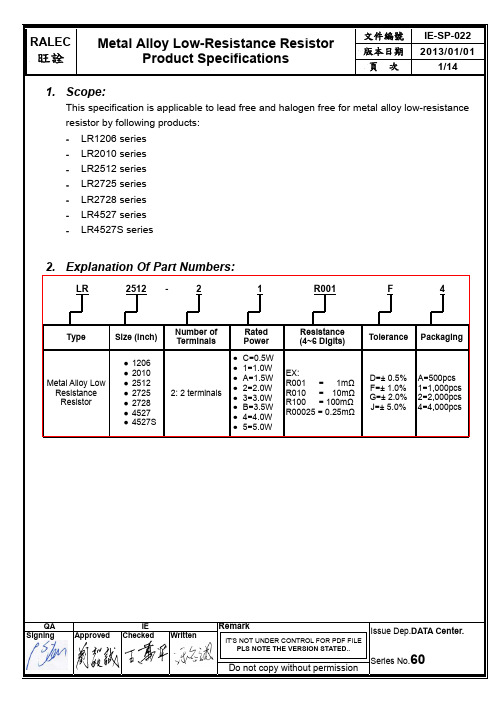
Ralec合金电阻规格书
(0.645±0.254) (0.787±0.254)
LR2512
LR2725 LR2728
0.5 ~ 3.0
1.0 & 1.5
3.1 ~ 4.0 4.1 ~75.0
75.1 ~ 100.0
0.5 ~ 3.0
2.0
3.1 ~ 4.0
0.246±0.010 (6.248±0.254)
4.1 ~75.0
文件編號 版本日期 頁次
IE-SP-022 2013/01/01
3/14
3.1 Power Derating Curve: Operating Temperature Range: - 55 ~+170 ℃ For resistors operated in ambient temperatures 70°C, power rating shell be derated in accordance with the curve below:
Do not copy without permission
Issue Dep.DATA Center.
Series No.60
RALEC
旺詮
Metal Alloy Low-Resistance Resistor Product Specifications
文件編號 版本日期 頁次
IE-SP-022 2013/01/01
5/14
Type LR4527S (without heat sink)
LR4527
Maximum
Power Resistance
Rating Range (mΩ)
L
(Watts)
Dimensions - in inches (millimeters)
合金电阻 2512 0.0015Ω(1.5mR) ±5% 2W 合金

本文主要介绍合金电阻2512 0.0015Ω(1.5mR) ±5% 2W 合金详情,合金电阻是一种采用合金为电流介质的电阻,一般具有低阻值,高精密,低温度系数,耐冲击电流,大功率等特点。
合金电阻由于金属的导电率强,所以阻值一般较低如1毫欧,10毫欧,100毫欧等。
所以常常用于电路中电流的采样,用于反馈电路中变化的电流,以便进一步地控制或影响电流的变化。
合金电阻2512 0.0015Ω(1.5mR) ±5% 2W 合金商品信息
商品编码06SUP012670
原厂编码MRF6432(2512)LR1M5JTS
品牌美隆(SUP)
毛重0.08
封装规格2512(6432)
阻值0.0015Ω
精度±5%
功率2W
商品型号合金电阻2512 0.0015Ω(1.5mR) ±5% 2W 合金
合金电阻2512 0.0015Ω(1.5mR) ±5% 2W 合金,全部来自原厂,10PCS起订,合金电阻2512
0.0015Ω(1.5mR) ±5% 2W 合金价格0.1677。
以上就是合金电阻2512 0.0015Ω(1.5mR) ±5% 2W 合金详情,希望对各位有帮助。
Resistor.Today-KWSL系列四脚开尔文合金采样电阻规格书

焊脚温度( ℃)
额定功率 (%)
0
0
Q
9
系列号 KWSL
精度 F=±1% G=±2% J=±5%
阻值
L300=0.3mΩ L500=0.5mΩ 1L00=1mΩ 2L00=2mΩ 3L00=3mΩ
KWSLF1L00Q9 5W 1mΩ ±50ppm 6.6±0.3 6.9±0.3 3.0±0.3 4.8 0.9 2.5 0.33
KWSLF2L00M9 5W 2mΩ ±20ppm 6.6±0.3 6.9±0.3 3.0±0.3 4.8 0.9 2.5 0.50
KWSLF3L00M9 4W 3mΩ ±20ppm 6.6±0.3 6.9±0.3 3.0±0.3 4.8 0.9 2.5 0.34
温飘 M=±20ppm Q=±50ppm
包装 9=标准品
85℃ ,85% RH ,10% 额定功,率 1000 h 100 g 6 ms ,5 个脉冲
10 Hz to 200 Hz 1分钟,频率变化 , 3 个方向, 12h 1000h at+70℃,1.5h开,0.5h关,额定功率 + 260℃锡槽,保持10s
参数
± (1.0%+0.0005Ω)ΔR ± (0.5%+0.0005Ω)ΔR ± (0.5%+0.0005Ω)ΔR ± (1.0%+0.0005Ω)ΔR ± (0.5%+0.0005Ω)ΔR ± (0.5%+0.0005Ω)ΔR ± (0.5%+0.0005Ω)ΔR ± (1.0%+0.0005Ω)ΔR ± (0.5%+0.0005Ω)ΔR
2512 0.015R 合金电阻_顺海科技
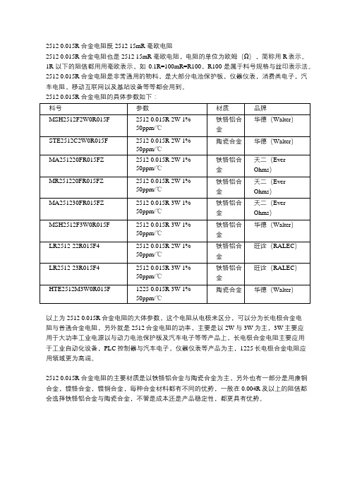
2512 0.015R 合金电阻既2512 15mR 毫欧电阻
2512 0.015R 合金电阻也是2512 15mR 毫欧电阻,电阻的单位为欧姆(Ω),简称用R表示。
1R以下的阻值都用用毫欧表示,如0.1R=100mR=R100,R100是属于料号规格与丝印表示法。
2512 0.015R 合金电阻是非常通用的物料,是大部分电池保护板,仪器仪表,消费类电子,汽车电阻,移动互联网以及基站设备等等都会用到。
2512 0.015R 合金电阻的具体参数如下:
以上为2512 0.015R合金电阻的大体参数,这个电阻从电极来区分,可以分为长电极合金电
阻与普通合金电阻,另外就是2512合金电阻的功率,主要是以2W与3W为主,3W主要应
用于大功率工业电源以与动力电池保护板及汽车电子等等产品上,长电极合金电阻主要应用
于工业自动化设备,PLC控制器与汽车电子,仪器仪表等产品为主,1225长电极合金电阻应
用领域更为高端。
2512 0.015R 合金电阻的主要材质是以铁铬铝合金与陶瓷合金为主,另外也有一部分是用康铜合金,镍铬合金,镍铜合金,每种合金材料都有不同的优势,一般在0.004R及以上的阻值都会选择铁铬铝合金与陶瓷合金,不管是成本还是产品稳定性,都更具有优势。
Resistor.Today-EWSL系列合金采样电阻规格书

额定功率 (%)
降功耗曲线
120 100
80 60 40 20
0 -10 10 30 50 70 90 110 130 150 170 190 210 230 250
焊脚温度( ℃)
合金温度系数
电阻温度 (ppm)
160
130
90
70
50
30
10 20 30 40 50 60 70 80 90 100 110 120
1000h at +70℃ ,1.5h 开 ,0.5h 关,额定功率 + 260℃锡槽 ,保持10s
参数
± (1.0%+0.0005Ω)ΔR ± (0.5%+0.0005Ω)ΔR ± (0.5%+0.0005Ω)ΔR ± (1.0%+0.0005Ω)ΔR ± (0.5%+0.0005Ω)ΔR ± (0.5%+0.0005Ω)ΔR ± (0.5%+0.0005Ω)ΔR ± (1.0%+0.0005Ω)ΔR ± (0.5%+0.0005Ω)ΔR
5.5±0.3 15±0.3
T
1.2±0.2 2.2±0.2 4.2±0.3
A
3.1±0.3 5.1±0.3 7.6±0.4
H*
1±0.1 1.5±0.1 1.5±0.1
A
H
W *高度根据具体阻值功率不同而不同,具体情况请咨询我司销售工程师
B T
性能参数
测试项目
热冲击 短时过载 低温存储 高温暴露
抗潮湿 冲击 震动
负载寿命 耐焊接热
测试条件
-55°C 15分钟 ~常温<20秒~+155°C 15分钟, 1000个循环 5 x 额定功率 5 s -65℃ 45分钟
50w铝壳电阻规格书
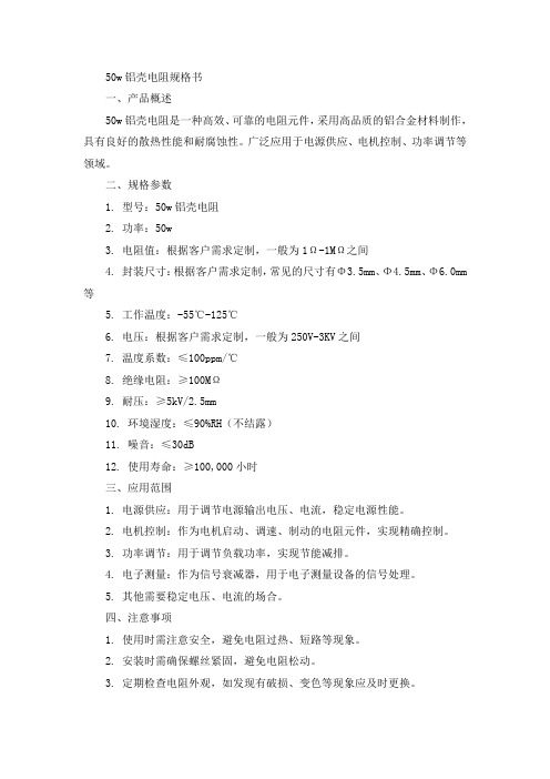
50w铝壳电阻规格书一、产品概述50w铝壳电阻是一种高效、可靠的电阻元件,采用高品质的铝合金材料制作,具有良好的散热性能和耐腐蚀性。
广泛应用于电源供应、电机控制、功率调节等领域。
二、规格参数1. 型号:50w铝壳电阻2. 功率:50w3. 电阻值:根据客户需求定制,一般为1Ω-1MΩ之间4. 封装尺寸:根据客户需求定制,常见的尺寸有Φ3.5mm、Φ4.5mm、Φ6.0mm 等5. 工作温度:-55℃-125℃6. 电压:根据客户需求定制,一般为250V-3KV之间7. 温度系数:≤100ppm/℃8. 绝缘电阻:≥100MΩ9. 耐压:≥5kV/2.5mm10. 环境湿度:≤90%RH(不结露)11. 噪音:≤30dB12. 使用寿命:≥100,000小时三、应用范围1. 电源供应:用于调节电源输出电压、电流,稳定电源性能。
2. 电机控制:作为电机启动、调速、制动的电阻元件,实现精确控制。
3. 功率调节:用于调节负载功率,实现节能减排。
4. 电子测量:作为信号衰减器,用于电子测量设备的信号处理。
5. 其他需要稳定电压、电流的场合。
四、注意事项1. 使用时需注意安全,避免电阻过热、短路等现象。
2. 安装时需确保螺丝紧固,避免电阻松动。
3. 定期检查电阻外观,如发现有破损、变色等现象应及时更换。
五、使用与维护1. 使用前应仔细阅读产品说明书,了解产品的各项参数和使用要求。
2. 安装时应确保电阻垂直放置,螺丝紧固,避免受力不均导致电阻损坏。
3. 使用过程中应定期检查电阻的工作状态,如发现异常应及时处理。
4. 维护时应注意安全,避免带电操作。
5. 更换电阻时应选用相同规格的产品,避免不匹配导致性能下降或损坏。
50w铝壳电阻规格书

50w铝壳电阻规格书全文共四篇示例,供读者参考第一篇示例:50W铝壳电阻是一种重要的电子元件,广泛应用于电力、电信、医疗等领域。
为了更好的了解和使用50W铝壳电阻,制作一份规格书是至关重要的。
下面将详细介绍50W铝壳电阻的规格书内容。
一、型号:50W铝壳电阻的型号通常是根据其电阻值和容差来命名的,如50W1RJ表示50W铝壳电阻的电阻值为1欧姆,容差为5%。
二、额定功率:50W铝壳电阻的额定功率为50W,即在正常工作条件下,可连续工作的最大功率。
三、电阻值范围:50W铝壳电阻的电阻值范围通常为几欧姆至几百欧姆,用户可以根据具体需要选择合适的型号。
四、容差:50W铝壳电阻的容差通常为±1%,±5%,±10%,±20%等,通过容差可以了解电阻值的准确度。
五、工作温度:50W铝壳电阻的工作温度通常为-40℃至+125℃,具有良好的稳定性和可靠性。
六、绝缘电阻:50W铝壳电阻的绝缘电阻通常大于1000MΩ,确保在工作过程中不会发生漏电现象。
七、介质耐压:50W铝壳电阻的介质耐压通常为500VAC,具有良好的安全性能。
八、外壳材料:50W铝壳电阻的外壳材料为铝合金,具有良好的散热性能和强韧性。
九、引线材料:50W铝壳电阻的引线材料通常为镀锡铜线,确保连接稳固可靠。
十、尺寸:50W铝壳电阻的尺寸通常为50mm×20mm,体积小巧,便于安装和维护。
十一、应用领域:50W铝壳电阻广泛应用于电源、稳压、电子仪器等领域,具有可靠性高、散热好等优点。
通过以上介绍,我们可以了解到50W铝壳电阻的规格书内容,了解其性能参数和应用领域,有助于更好地选择和使用50W铝壳电阻。
希望以上内容对大家有所帮助。
第二篇示例:50w铝壳电阻是一种常见的电子元器件,广泛应用于各种电子设备中。
它具有耐高温、耐压、耐腐蚀等特点,适用于各类电路中的电阻调节及稳压任务。
本文将详细介绍50w铝壳电阻的规格书,给大家提供更多关于该产品的信息。
合金电阻规格书
阻值
LR001:0.001R LR010:0.01R LR3M5:0.0035R
误差
B:±0.1% C:±0.25% D:±0.5%
F:±1% J:±5%
■ 标准电性参数
普通产品电性标准电性参数
封装 额定功率 工作温度范围
最大 工作电压
阻值范围
功率
B:2.5W A:1.5W Q:3/4W U:1/2W O:1/3W V:1/4W W:1/8W
封装
L
2512
6.4±0.2
3.2±0.2 W
3.2±0.2
2.0±0.2 (R≦3mΩ) 0.9±0.2 (R>3mΩ)
C
2.0±0.2 (R≦4mΩ) 0.9±0.2 (R>4mΩ)
t 0.6±0.20
0.6±0.20 t
0.7±0.20
■ 物料编码
合金贴片电阻
RL
2512
LR001
J
2
T
类型 RL:合金电阻
2512
1W 1.5W
2W 3W
1W 1.5W
-55℃~+170℃
√(P*R)
1mΩ≦R≦100mΩ
±1% ±2% ±5%
100mΩ≦R≦500mΩ
>100MΩ
±75PPM/℃
■ 特点:
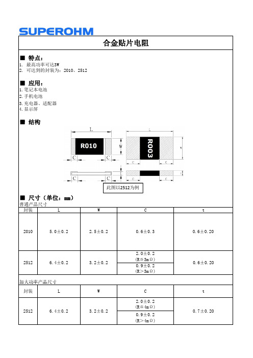
1. 最高功率可达3W 2. 可达到的封装为:2010、2512
■ 应用:
1.笔记本电池 2.手机电池 3.充电器、适配器 4.显示屏
■ 结构
合金贴片电阻
■ 尺寸(单位:mm)
普通产品尺寸
封装
L
此图以2512为例
W
C
2010
5.0±0.2
6J22康铜合金精密电阻合金标准
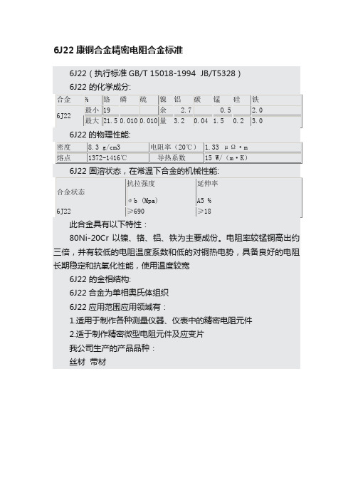
6J22 的金相结构:
6J22合金为单相奥氏体组织
6J22应用范围应用领域有:
1.适用于制作各种测量仪器、仪表中的精密电阻元件
2.适于制作精密微型电阻元件及应变片
0.010
0.010
量
3.2
0.04
1.5
0.2
3.0
6J22的物理性能:
密度
8.3 g/cm3
电阻率(20℃)
1.33 μΩ·m
熔点
1372-1416℃
导热系数
15 W/(m·K)
6J22 固溶状态,在常温下合金的机械性能:
合金状态
抗拉强度
σb (Mpa)
延伸率
A5 %
6J22
≥690
≥18
此合金具有以下特性:
电阻率较锰铜高出约三倍并有较低的电阻温度系数和低的对铜热电势具备良好的电阻长期稳定和抗氧化性能使用温度较宽
6J22康铜合金精密电阻合金标准
6J22(执行标准GB/T 15018-1994 JB/T5328)
6J22 的化学成分:
合金
%
铬
磷
硫
镍
铝
碳
锰
硅
铁
6J22
最小
19
余
2.7
0.5
2.0
最大
21.5ቤተ መጻሕፍቲ ባይዱ
我公司生产的产品品种:
丝材 带材
PDC信昌FMF系列大功率合金采样电阻选型规格书

1. Features (2)2. Applications (2)3. Dimension and construction (2)4. Power Derating Curve (2)5. Rating (3)6. Part Number (5)7. Resistance Marking (5)8. Reliability Performance (6)9. Packing (9)10. Storage &. Handling (10)1. FeaturesHigh power rating and low TCR.Low resistance and high precision (1%).Low inductance design, less than 1.0nH available.Excellent reliability and suitable cost. Suitable for lead free soldering.High precision trimming implement.RoHS compliant & Halogen Free.2.ApplicationsSwitching model power supply. Battery pack. Notebook, Tablet PC Test Instrument. Power Amplifier.3.Dimension and ConstructionProtective MoldingTerminationResistive AlloyWItem Protective Molding Resistive Element Internal Terminal External TerminalMaterial Resin Alloy Metal Copper SolderUnit :mmType LW T aFMF06 5m~30m 3.10±0.20 1.65±0.20 0.60±0.20 0.60±0.20 FMF25 3m~220m 6.20±0.20 3.25±0.20 0.60±0.20 0.80±0.20 FMF25 3W series 6.20±0.20 3.25±0.20 0.65±0.20 0.80±0.20 FMF25 1m~2m 6.40±0.20 3.25±0.20 0.70±0.20 2.00±0.20 FMF59 2~10m 15.0±0.20 7.80±0.20 0.70±0.20 3.50±0.204.Power Derating CurveOperating Temperature Range: -55 to +170 deg.CR0055.RatingNote:P*or Max. Working Voltage whichever is lower.=R(i) E(ii) E:Working Voltage(V),P:Rated Power (W),R:Resistance Value(Ω)(iii) Solder-pad and trace size should be >300 mm2 and board surface temperature should not exceed 105℃when applying rated power(iv) * : Related number are depend on specific items only. ** : TCR Hot (+25~+155℃).*** : Special requests and details please contact factory.Note:(v) E =R P * or Max. Working Voltage whichever is lower. (vi) E :Working Voltage(V),P :Rated Power (W),R :Resistance Value(Ω)(vii) Solder-pad and trace size should be >300 mm 2 and board surface temperature should not exceed 105℃ when applying rated power(viii)* : Related number are depend on specific items only. ** : TCR Hot (+25~+155℃). *** : Special requests and details please contact factory.T ※Temperature Coefficient Resistance not applicable.6.Part NumberType Size Tolerance PackingWatt Value TCR Special Code FMF 06 :1206 25 :2512 59 :5931F :±1%G :±2%J :±5% T :Paper Tape 4Kpcs (For 1206) P :Plastic Tape 4Kpcs (For 2512) Q :Plastic Tape 3Kpcs (For 5931)F : 1/2W H : 1W J : 2W K : 3W M : 5WXXXX 4 digitJumper : 000__: means blank.-: As Rating Info X: Code of R001.R002.General LH :Standard BH :Low EMF AEC-Q200 LHM : Standard BHM : Low EMFExample :FMF25FPJR005-BH→Metal strip, 2512 size, ±1%, plastic tape, 2W, 5m Ω, low emfFMF25FPKR010-BHM→Metal strip, 2512 size, ±1%, plastic tape, 3W, 10m Ω, low emf, AEC-Q200FMF25FPJR002XBH→Metal strip, 2512 size, ±1%, plastic tape, 2W, 2m Ω, low emf, General7.MarkingFMF 1206/2512/5931TOP :Marking. (4 Digits marking to identify the resistance value.)5m Ω/15L5=15.5m 1 m ΩRecommend Solder Pad Dimensions :Unit:mmType W D L FMF06 1.80 1.30 4.70 FMF25 3.70 1.60 7.60 FMF25 R001/R002 4.00 3.00 7.308.75 6.00 17.608. Reliability Performance (AEC-Q200) *Normal test items for standard product.Test Item SpecificationTest Method (AEC-Q200. IEC 60115)*DC Resistance F:±1%、G:±2%、J:±5%AEC-Q200 TABLE 7.1IEC 60115-1 / JIS C 5201-1 , Clause 4.5 Measurethe resistance Value.High Temperature Exposure (Storage) J、G:△R≦ ±(3%+0.5mΩ)F:△R≦ ±(1%+0.5mΩ)AEC-Q200 TABLE 7.31000 hrs. @ T=125℃. Unpowered.Measurement at 24 ±2 hours after test conclusion.*Temperature Cycling J、G:∆R≦ ±(1%+1mΩ)F:∆R≦ ±(0.5%+1mΩ)No mechanical damage.AEC-Q200 TABLE 7.41000 Cycles (-55°C to +125°C). Measurement at24±2 hours after test conclusion.Moisture Resistance J、G:△R≦ ±(1%+0.5mΩ)F:△R≦ ±(0.5%+0.5mΩ)AEC-Q200 TABLE 7.6Test 65℃/80~100%RH/10Cycles.Measurement at 24±2 hours after test conclusion.(t=24hrs/cycle).Biased Humidity J、G:△R≦ ±(3%+0.5mΩ)F:△R≦ ±(1%+0.5mΩ)AEC-Q200 TABLE 7.71000 hours 85/85%RH.℃10% of operating power.Measurement at 24 ±2 hours after test conclusion.Operational Life J、G:△R≦ ±(3%+0.5mΩ)F:△R≦ ±(1%+0.5mΩ)AEC-Q200 TABLE 7.8Test 1000hr @ TA=125℃ at specified rated power.Measurement at 24±2 hours after test conclusion.External Visual No visual damage and referPDC marking code. AEC-Q200 TABLE 7.9Inspect device construction, marking and workmanship.Physical Dimension Within the spec. AEC-Q200 TABLE 7.10Verify physical dimensions to the applicable devicedetail specification.Mechanical ShockWithin product specification tolerance and no visible damage.AEC-Q200 TABLE7.13 Test Peak value:100g's,Wave:Hail-sine, Duration:6ms,Velocity:12.3ft/sec. Vibration No mechanical damage.AEC-Q200 TABLE 7.145 g's for 20 min., 12 cycles each of 3 orientations. Test from 10-2000 Hz.*Resistance toSolder HeatJ 、G :∆R ≦ ±(1%+0.5m Ω) F :∆R ≦ ±(0.5%+0.5m Ω) No mechanical damage.AEC-Q200 TABLE 7.15 Solder dipping @ 270±℃5 ℃for 10sec.±1sec. Thermal Shock J 、G :∆R ≦ ±(1%+0.5m Ω) F :∆R ≦ ±(0.5%+0.5m Ω) No mechanical damage.AEC-Q200 TABLE 7.16-55 to 155/ dwell time 15min/ Max transfer time ℃20sec/ 300cycles. ESD∆R ≦ ±(1%+0.5m Ω) No mechanical damage.AEC-Q200-002 Test contact min. 1KV.*Solder Ability Over 95% of termination must be covered with solder.AEC-Q200 TABLE 7.18a)Baking 155℃ 4H, dipping 235℃ 5s b)Steam 1H, dipping 215℃ 5s c)Steam 1H, dipping 260℃ 7sFlammability Refer UL-94. AEC-Q200 TABLE 7.20 UL-94 V-0 or V-1 are acceptable*Board FlexJ 、G :∆R ≦ ±(1%+1m Ω) F :∆R ≦ ±(0.5%+1m Ω) No mechanical damage.AEC-Q200 TABLE 7.21 Bending 2mm 5931.2512.1206TerminalStrengthNo mechanical damageAEC-Q200 TABLE 7.22 Force 1 Kg for 60 seconds.*Short TimeOverloadJ 、G :∆R ≦ ±(2%+0.5m Ω) F :∆R ≦ ±(1%+0.5m Ω) IEC 60115-1, Clause 4.13 5 × Rated power for 5 seconds*Load Life Humidity J、G:△R≦ ±(3%+0.5mΩ)F:△R≦ ±(1%+0.5mΩ)IEC 60115-1, Clause 4.2440±2 with℃relative humidity90% ~ 95% D.C. rated voltage for1.5 hours ON 30 minutes OFF.Cycle repeated 1000 hours.*Temperature Coefficient of Resistance (TCR) Within the spec. IEC 60115-1, Clause 4.8T1T2Test temperature: 25~℃ +155℃TCR(ppm/℃) = (R2-R1)/R1×1 / (T2-T1)×106( +25~ -55℃ please contact factory. )*Load Life J、G:△R≦ ±(3%+0.5mΩ)F:△R≦ ±(1%+0.5mΩ) IEC 60115-1, Clause 4.25Rated voltage for 1.5 hours for followed by a pause 0.5 hour at 70±2℃.Cycle repeated 1000 hours.*Insulation Resistance Between termination andcoating must over 1000MΩIEC 60115-1, Clause 4.6Test voltage:100±15V9. PACKAGING9.1 Peel Strength of Top Cover TapeThe peel speed shall be about 300 mm/minThe peel force of top cover tape shall between 0.1 to 0.7N9.2 Tape Packaging DimensionsSize A B W F E P1 P2 P0 D 1206 2.00±0.20 3.60±0.20 8.00±0.30 3.50±0.051.75±0.104.00±0.102.00±0.05 4.00±0.10 1.50±0.10 2512 3.50±0.20 6.75±0.20 12.0±0.30 5.50±0.051.75±0.104.00±0.102.00±0.05 4.00±0.10 1.50±0.10 5931 8.20±0.10 15.4±0.10 24.0±0.30 11.5±0.101.75±0.1012±0.10 2.00±0.10 4.00±0.10 1.50±0.10unit:mm9.3 Reel DimensionsSizePackagingQ’tyA N C DB G T1206 4kpcs/Reel 178.0±2.0 60.0±0.513.0±0.520(Min.) 2.0±0.510.0±1.5 14.9max.25124kpcs/Reel178.0±2.0 60.0±0.513.0±0.520(Min.) 2.0±0.513.8±1.5 16.7max.8kpcs/Reel254.0±2.0 100.0±0.513.5±0.520(Min.) 2.0±0.513.8±1.5 20.0max.16kpcs/Reel 330.0±2.0 100.0±1.013.5±0.520(Min.) 2.0±0.513.8±1.5 20.0max.5931 3kpcs/Reel 330.0±2.0 99.5±1.013.0±0.520(Min.)2.0±0.524.0±1.0 28.6max.10. Storage &. Handling… Products are recommended to be used up within one year as ensured shelf life. Check solder ability in case shelf life extension is needed. … To store products with following condition:Temperature:5 to 40℃;Humidity: 20 to 70% relative humidity.Precaution for use :The AEC-Q200 series resistors is mainly used on general automotive equipment without safety considerations. Please contact our company in advanced if you intend to use resistor for designing the equipment which may damage itself and the safety of third party. If necessary, please consider to add the protect circuit in devising process and obtaining fully safety evaluation. The contents of the acknowledgment is only used for our parent company, marketing subsidiaries and official marketing agents who purchase our products. Not applicable for the other nonofficial channels.※ All product specification and data are subject to change without notice.。
大毅合金电阻规格书-RLP系列
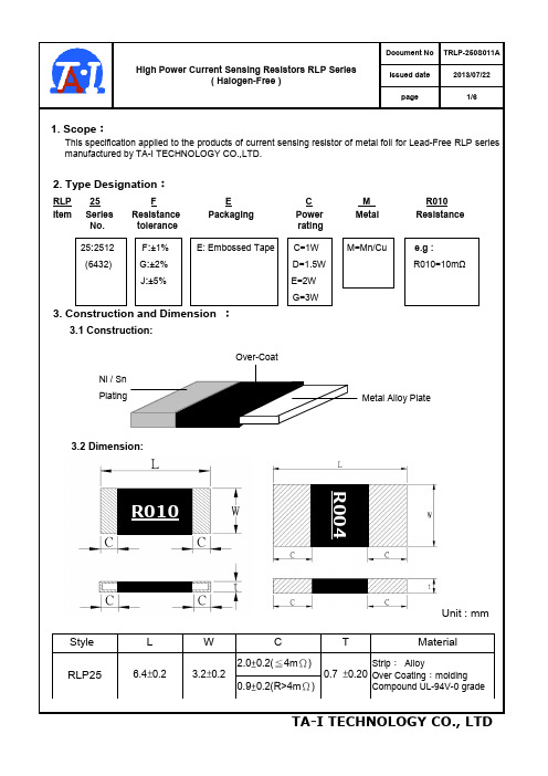
TRLP-250S011A
Issued date
2013/07/22
page
1/6
High Power Current Sensing Resistors RLP Series
( Halogen-Free )
1. Scope:
This specification applied to the products of current sensing resistor of metal foil for Lead-Free RLP series
Tel: (+886) 3-3246169
Fax : (+886) 3-3246167
Associated companies :
(1)TA-I TECHNOLOGY ( SU ZHOU ) CO., LTD. ( China – Su Zhou)
Tel :(+86) 512-63457879
Fax : (+86) 512-63457869
Fax : (+60) 4-3901481
(5) P.T.TAI ELECTRONIC Indonesia ( Indonesia – Jakarta )
Tel :(+62) 21-44820254
Fax : (+62) 21-44820256
TA-I TECHNOLOGY CO., LTD
Tolerance
Insulation Resistance
Maximum Working Current( I )
5. Reliability Tests :
Test Items
Temperature Coefficient
- 1、下载文档前请自行甄别文档内容的完整性,平台不提供额外的编辑、内容补充、找答案等附加服务。
- 2、"仅部分预览"的文档,不可在线预览部分如存在完整性等问题,可反馈申请退款(可完整预览的文档不适用该条件!)。
- 3、如文档侵犯您的权益,请联系客服反馈,我们会尽快为您处理(人工客服工作时间:9:00-18:30)。
体积
0805 1206 2512
阻值
LR001:0.001R LR010:0.01R LR3M5:0.0035R
误差
B:±0.1% C:±0.25% D:±0.5%
F:±1% J:±5%
■ 标准电性参数
普通产品电性标准电性参数
封装 额定功率 工作温度范围
最大 工作电压
阻值范围
功率
B:2.5W A:1.5W Q:3/4W U:1/2W O:1/3W V:1/4W W:1/8W
2mΩ≦R≦50mΩ R≦15mΩ R≦10mΩ
±1% ±2% ±5%
>100MΩ
±275PPM/℃ (R≦1mΩ)
±100PPM/℃ (1mΩ<R≦10m
Ω) ±75PPM/℃ (R>10mΩ)
加大功率产品电性标准电性参数
封装
额定功率
工作温度范围
最大 工作电压
阻值范围
精度 绝缘阻值温度系数(PPM/℃) Nhomakorabea2512
1W 1.5W
2W 3W
1W 1.5W
-55℃~+170℃
√(P*R)
1mΩ≦R≦100mΩ
±1% ±2% ±5%
100mΩ≦R≦500mΩ
>100MΩ
±75PPM/℃
■ 特点:
1. 最高功率可达3W 2. 可达到的封装为:2010、2512
■ 应用:
1.笔记本电池 2.手机电池 3.充电器、适配器 4.显示屏
■ 结构
合金贴片电阻
■ 尺寸(单位:mm)
普通产品尺寸
封装
L
此图以2512为例
W
C
2010
5.0±0.2
2.5±0.2
0.6±0.3
2512
6.4±0.2
加大功率产品尺寸
包装 卷轴包装
精度 绝缘阻值温度系数(PPM/℃)
2010
1/2W 3/4W
1W 1.5W
-55℃~+170℃ √(P*R)
5mΩ≦R≦30mΩ
±1% ±2% ±5%
±100PPM/℃
(5mΩ≦R≦10m
>100MΩ Ω)
±
75PPM/℃
(R>10mΩ)
2512
1W 1.5W
2W
-55℃~+170℃ √(P*R)
封装
L
2512
6.4±0.2
3.2±0.2 W
3.2±0.2
2.0±0.2 (R≦3mΩ) 0.9±0.2 (R>3mΩ)
C
2.0±0.2 (R≦4mΩ) 0.9±0.2 (R>4mΩ)
t 0.6±0.20
0.6±0.20 t
0.7±0.20
■ 物料编码
合金贴片电阻
RL
2512
LR001
J
2
T
类型 RL:合金电阻
