最新 喷嘴大全说明书印刷版双面 20100808
Parker Hannifin SD 7200喷雾胶结剂喷嘴说明书

Product Features and Benefits:• Pneumatically powered, no explosion risk, no electricity required, adaptable worldwide • Completely sealed, minimal exposure to fumes• Solvent applied only where you want it, providing accurate consistent bonds with no solvent waste • O.D., I.D. bonding or both simultaneously, for improved operator efficiency • Non-clogging design for minimal downtimeSD 7200Solvent DispenserContact Information:Parker Hannifin CorporationComposite Sealing Systems Division 7664 Panasonic WaySan Diego, CA 92154 USA phone 619 661 7000fax 619 671 3208*******************Solvent Dispensing:A vast number of medical and non-medical products are assembled using plastics joining solvents. Traditionally, these assemblies have been made by dipping the components into a small container of solvent and then blotting away the excess. This method although effective, presents a number of issues:• The operator is exposed to high levels of solvent vapor.• The wetting of the component is inconsistent as the depth of solvent in the container is constantly varying.• The operator is less efficient due to the wasted motion of blotting.• Solvent usage is increased due to blotting.• There is a fire hazard associatedwith solvent in an open container.Solvent DispensingAfter years of using the dip and blot method and struggling with the few commercially available dispensers, we designed the SD7200. Sinceits introduction, the SD7200 has become the product of choice for many of the world’s largest medical device manufacturers. Due to the value engineered design it is also selected by much smaller firms as well. The product is so versatile,it is used by several companies to apply other fluids such as silicone lubricants to components.The Parker SD7200 Solvent Dispenser represents a break though in solvent dispensing technology. From the ground up, this dispenser has been engineered with diverse medical bonding in mind. Designed for the operator, the technician, the manufacturing/ process engineer and the safety manager, the model SD7200 is unsurpassed in performance, reliability and safety. PRINCIPLE OF OPERATIONThe SD7200 consists of two primary subsystems: A pump drive module and a fluid delivery module.The pump drive module is100% pneumatically operatedto minimize explosion hazards associated with solvent dispensing. Plant line air is coupled to the dispenser with a standard quick disconnect fitting. A dual actingair cylinder is controlled by an air bearing, pneumatically piloted control valve. This bidirectional valve is speed controlled by a precision integral regulator to allow repeatable metering of solvent. The fluid delivery moduleconsists of a primary reservoir, apositive displacement pump, asecondary reservoir and a solventapplicator. Solvent is transportedfrom the primary reservoir to thesecondary reservoir by a fullysubmerged piston pump. Thispump is actuated by the pumpdrive module described above.The solvent is then gravity fed fromthe secondary reservoir into theapplication area. A solvent film isuniformly applied to the desiredcomponent by transfer fromnon clogging porous materialscontained in the applicator.DESIGN CRITERIAThe Parker SD7200 is designed andmanufactured to provide highlyaccurate uniform dispensingwith a minimum of effort and amaximum of operator safety. Theproduct will perform reliably on awide range of external diameters,internal diameters, and bothsimultaneously.PERFORMANCEAccurate Uniform Wetting:Uniform and consistent wetting isa primary objective in achievingreliable repeatable solvent bonds.Using the integral regulator, theParker SD7200 is adjustableover a broad range of solventdelivery rates. The right amountof solvent is applied to the desiredcomponent without the need forpart rotation. As part diametersvary, solvent delivery can beadjusted to match. The regulator issupplied with an adjustment guardto prevent unauthorized changesonce the optimal setting is made.Uniform wetting is assured byusing porous application materialsin a size and shape specific to yourparts. Porous materials have beenproven to apply highly consistentfilms of solvent when the surfaceis continually fed under slightpositive pressure.I.D. and O.D. Bonding, or BothSimultaneously:Parker suppliesapplicators to apply solvent oninternal surfaces, external surfaces,or both simultaneously. Allapplicators are interchangeablemaking the SD7200 extremelyversatile. The ability to applysolvent to I.D. and O.D. surfacessimultaneously saves theoperator time while facilitatinga more consistent bond thancan be obtained from a two stepapplication process.Anti-Capillary Action:Withtraditional solvent applicationmethods, small inside diametercomponents are prone toundesirable capillary filling.When this happens, the operatormust take extra steps to removethe excess solvent. The removalprocess not only subjects theoperator to additional vapors orsolvent mist, but also increasessolvent consumption by as muchas 80%. The Parker SD7200 can beregulated so that capillary actionis eliminated simply by adjustingthe solvent delivery rate with theintegral precision regulator. Theuse of porous application materialsalso helps assure an optimalvolume of solvent is present at alltimes. The net effect is shortenedassembly time, reduced solventusage and minimized scrap.Drip Stop Applicators: The unique design of the applicator prevents solvent droplets from pooling on the end of the component and then being inadvertently withdrawn into the work area. This feature keeps the work area clean, minimizes solvent waste, and controls vapors. SAFETYVapor Control: The generation of potentially harmful vapors is an undesirable side effect of solvent dispensing. The Parker SD7200 dispenser has been specifically designed to minimize solvent vapor exposure without the use of cumbersome and expensive vapor removal systems. The pump shaft incorporates a PTFE spring loaded seal to prevent solvent in the primary reservoir from entering the pump drive module. The fluid path is integrated into the pump housing to eliminate tubing, connections, and potential leaks. Finally, solvent inert gaskets have been provided at all fluid interfaces, leaving only the immediate application opening in contact with the room atmosphere. 100% Pneumatically Operated: Since many common bonding solvents are flammable, the Parker SD7200 has been engineered to use only pneumatically driven powertrain components. There are no electrical power requirements. Air logic circuitry provides precise dispensing volume controlwhile minimizing the potentialfor explosions.Large Stable Base:The SD7200 has a low center of gravity to prevent accidental tipping. This further protects the operator from accidental solvent exposure and vapors. Safe Refilling: The SD7200 can beeasily and safely refilled at the workstation. The filler cap provides apositive seal and yet is easy to open.The filler hole is level with the top ofthe primary reservoir which assuresthe solvent head height is neverabove the pump drive module. Ahigh quality sight gauge is builtinto the reservoir to providecontinuous indication of the filllevel. The high volume primaryreservoir minimizes the frequencyof refilling and resulting solventand vapor exposure.CONVENIENCENon-Clogging Design:Theporous materials used in theapplicator area are continuouslyflushed by the gravity fed solvent.Unlike porous materials fedby wicking action, clogging isvirtually eliminated. The uniqueporous materials self clean eachtime a component is inserted.Although the use of clean solventsis recommended, a pump inletscreen is provided to preventpossible contaminates fromentering the fluid path.High Capacity Primary Reservoir:The Parker SD7200 holds one literof solvent. This will typically allowuninterrupted bonding for oneweek or more between refills.This minimizes down time andincreases throughput. In addition,many solvents are supplied in oneliter bottles. By using the entirebottle, time is saved in materialtransport and partially filledbottles are eliminated from theproduction floor.Easy Component Insertion:Applicators are available with avariety of tapered lead-ins to makepositioning components into theapplicator easier. This allowsthe operator to perform multipletasks simultaneously.Rugged and Stable:The size of themodel SD7200 provides a stablebase thus preventing it from slidingeven if the operator aggressivelypushes a large component intothe applicator. This allows thedispenser to be located in a varietyof work areas without requiringspecial mounting.Quick Applicator Exchanges: Ifa line changeover is required thedispenser applicator can be quicklyexchanged. The applicators arekeyed to make alignment positiveand easy.Universal Power Requirements:The SD7200 can be used wherevercompressed air is available.A simple change of the quickdisconnect coupling will allowoperation anywhere around theglobe without the concern forvoltage variations associatedwith electrically powereddispensing systems.CONFIGURATIONApplicators are custom made toyour components. Each ParkerModel SD7200 comes withone applicator of your choice.Applicators can also be orderedwith large tapered lead-ins tofacilitate easier componentlocation. All configurationsare interchangeable.SD7200 SpecificationsDELRIN® is a registered trademark of E.I. du Pont de Nemours and Company.© 2019 Parker Hannifin CorporationCSS 5915 06/19。
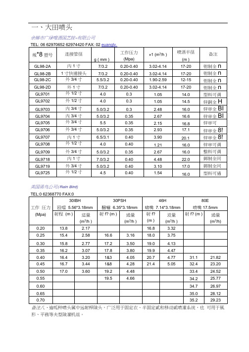
常用喷头参数表
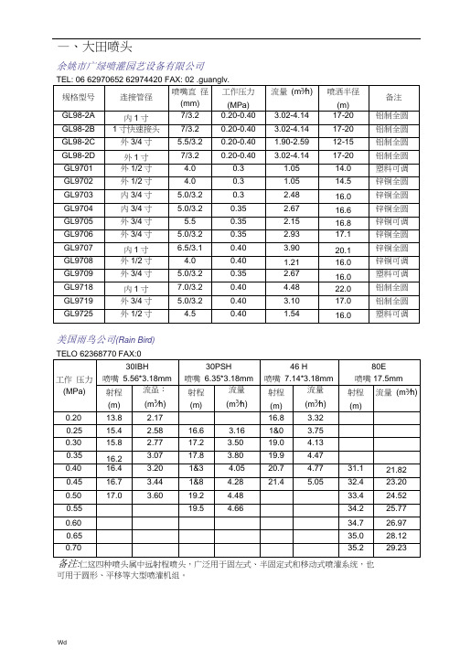
—、大田喷头余姚市广绿喷灌园艺设备有限公司美国雨鸟公司(Rain Bird):仁这四种喷头属中远射程喷头,广泛用于固左式、半固定式和移动式喷灌系统,也可用于圆形、平移等大型喷灌机组。
2、30IBH——接口为3/4寸外螺纹,喷头仰角23o, 3OPSH——接口为3/4寸外螺纹,喷头仰角27o, 46H—一接口为3/4寸外螺纹,喷头仰角23o, 80E一一接口为1.25寸外螺纹, 喷头仰角27。
C3、历经60多年不断改进的摇臂撞击式驱动机构,工作稳左可靠,H型减磨密封垫,寿命长,副喷嘴采用低喷射仰角,弥补近处水疑分布,均匀度高。
备注.• 1、该类喷头上装有换向机构,通过调整换向机构,喷头可在20。
~340。
范国内的任意角度内喷洒。
脱开换向机构,也可做全圆喷洒。
该类喷头适于布在场地边缘。
2、历经60多年不断改进的摇臂撞击式驱动机构,工作稳泄可靠:软一一硬一一软或软——硬型减磨密封垫,寿命长:独特的“雨鸟”式摇臂机构,动作灵活可靠。
3、2045PJ-08——接口为1/2寸外螺纹,喷头仰角23。
,35ATNT——接口为3/4寸外螺纹,喷头仰角27o, 65PJ——接口为1寸内螺纹,喷头仰角27o, 85EHD一一接口为1.25寸外螺纹,喷头仰角27%上海华维节水灌溉有限公司TEL: 9 FAX: 9锌合金摇臂式喷头(俗称锌鸟)配有换向机构,可以根据地块形状等调肖喷洒范用,将换向机构上翻,可作全圆喷洒,广泛用于园艺场、果菜园等开放式场所。
减磨密封垫,久经考验的撞击式驱动机构,锌铜合金材料,寿命长。
独特换向机构,动作灵活稳定,粉体烤漆,不掉漆,不褪色,可根据需要适当调节射程及液滴大小。
这两种喷头的接口尺寸为1/2寸外螺纹,喷头仰角23。
上海万得凯节水技术有限公司河南彩虹节水灌溉有限公司TEL: 0 5975924 FAX: 0371 -975924ZY-I型摇臂式全圆喷头ZY-2型摇臂式全圆喷头PΛ∖ZYH-I型摇臂式换向喷头二、地埋喷头以色列雷鸥灌溉公司TEL: 2 5975924 FAX: 3喷头型号:400G何调旋转喷头)喷头型号:7555(水涡轮驱动喷头)。
Alfa Laval GJ 10 液体驱动旋转喷头说明说明书
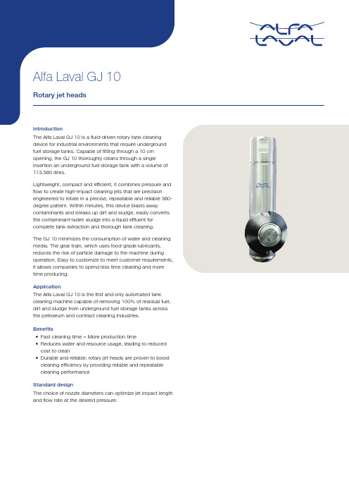
ApplicationThe Alfa Laval GJ 10 is the first and only automated tank cleaning machine capable of removing 100% of residual fuel, dirt and sludge from underground fuel storage tanks across the petroleum and contract cleaning industries.Benefits•Fast cleaning time = More production time•Reduces water and resource usage, leading to reduced cost to clean•Durable and reliable, rotary jet heads are proven to boost cleaning efficiency by providing reliable and repeatablecleaning performanceStandard designThe choice of nozzle diameters can optimize jet impact length and flow rate at the desired pressure.Working principleThe high-impact jet stream from the rotary jet head covers the entire surface 360° of the tank interior in a successively denser pattern. This achieves a powerful mechanical impact with a low volume of water and cleaning media.The flow of the cleaning fluid makes the nozzles perform a geared rotation around the vertical and horizontal axes. In the first cycle, the nozzles lay out a course pattern on the tank surface. The subsequent cycles gradually make the pattern denser until at full cleaning pattern is reached.Once the full cleaning pattern is reached, the machine will start over again and continue to perform the next full cleaning pattern.TECHNICAL DATAMax. throw length:10.5 mRecommended pressure: 3.5 - 18.5 barPHYSICAL DATAMax. ambient temperature:140 °CCautionAvoid hydraulic shock, hard and abrasive particles in the cleaning liquid, as this can cause increased wear and/or damage of internal mechanisms. In general, a filter in the supply line is recommended. Do not use for gas evacuation or air dispersion. For steaming we refer to the manual.Flow Ratem /h17161514131211109876542A = 9.5 mmB = 7.9 mmC = 6.4 mm468101214161820barInlet pressureNozzle 4126-0050ABCCleaning TimeStator4126-0052min201918171615141312111098763.4 6.49.412.415.418.421.424.4m /hAA = LPB = STDC = LVD = MVE = LMF = HVBCDEFImpact Throw LengthWettingImpact cleaningNozzle A 4126-0054BCA B Cm 2422.52119.51816.51513.51210.597.564.533456789101112bar210A = 2 x Ø6.4 mm B = 2 x Ø7.9 mm C = 2 x Ø9.5 mmInlet pressureDimensions (mm)This document and its contents are subject to copyrights and other intellectual property rights owned by Alfa Laval AB (publ) or any of its affiliates (jointly “Alfa Laval”). No part of this document may be copied, re-produced or transmitted in any form or by any means, or for any purpose, without Alfa Laval’s prior express written permission. Information and services provided in this document are made as a benefit and service to the user, and no representations or warranties are made about the accuracy or suitability of this information and these services for any purpose. All rights are reserved.200006316-2-EN-GB© Alfa Laval AB How to contact Alfa LavalUp-to-date Alfa Laval contact details for all countries are always availableon our website at 。
喷泉喷头型号及全参数整理.docx
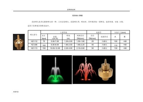
文案大全花柱喷头(银缨)喷头型号主要性能连接管安装尺寸(mm)水压(kpa)流量3 (m /h)喷咼(m) 喷洒直径DN(mm) 直径DN(mm) 连接形式 A BHZ-112 70 5.00-7.00 1.20-2.00 1.50-1.80 25 内螺纹 100 +60 HZ-306100 6.00-8.00 1.80-2.50 1.80-2.20 40 内螺纹 110 +60 HZ-11315010.00-12.002.20-3.002.10-2.6050内螺纹130+60花柱喷头是多孔散射喷头的一种,又名层花喷头、花篮喷头等。
喷水时,其外观形似一束鲜花,造型美观,安装 方便,适用于各种场合的喷水池中。
雾状喷头Foggy Nozzle雾状喷头它喷出的水滴非常细小,成为雾状,在阳光照射下可形成七色彩虹。
因喷嘴构造差异, 喷出的水姿也有不同,喷水时噪声小,用水量少,一般安装在雕像周围。
喷头型号主要性能连接管安装尺寸(mm) 水压(kpa)流量3(m3/h)喷咼(m)喷洒直径DN(mm)直径DN(mm)连接形式 A BWZ-112 105 0.60 1.60 1.50 20 内螺纹45 +20WZ-312 150 0.90 1.80 2.50 25 内螺纹76 +40WZ-407 250 1.80 2.00 3.00 40 内螺纹76 +40文案大全V文案大全中心直上喷头(集束)中心直上喷头是在同一个配水箱上安装许多万向直流喷嘴, 当这些喷嘴规格相同时,喷出的水姿雄壮笔直;当这些喷嘴规格不完全相同时,大小喷嘴布设得当,喷出的水姿粗壮有力,层次分明、主题突出,是大型喷泉必备的主要 喷头型号主要性能连接管安装尺寸(mm)水压(kpa)流量3 (m /h)喷咼(m) 喷洒直径DN(mm) 直径DN(mm) 连接形式 A B SZ-310 100-150 200-250 19-23 25-28 3-56-11 1.0-1.3 1.4-1.6 50 内螺纹 220 +120 SZ-212150-250 250-45029-38 52-607-10 11-161.6-1.82.0-2.565内螺纹280+120喷头。
RIELLO 40 F10燃油喷嘴说明书

RIELLO 40 F10TECHNICAL DATADIMENSIONSF10 - 1F10 - 2OIL BURNER COMPONENTS IDENTIFICATIONF10BURNER COMPONENTSSERIAL NUMBER IDENTIFICATIONThe Riello 15 character serial number, example, 97 A 8511111 00025, is identified as follows: 97 = last two digits of the year of manufacture; A = BI-week of manufacture;8511111 = burner product code; 00025 = increment of 1 for each burner produced - spe-cific to product code - reset to zero each January 1st .INITIAL SET -UPA)Remove burner and air tube from cartons. Check parts list (inside cover) to ensureall parts are present.B)Remove burner cover by loosening the three screws securing it. Remove control box and air tube cover (see page 7).C)Remove drawer assembly from air tube, insert nozzle and set turbulator adjustment for specific input required (see pages 7 & 8), then set aside.D)Mount air tube to burner chassis (see page 3).1.Lockout indicator lamp and Reset button2.Primary control3.Primary control sub-base4.Pump pressure regulator adjustment screw5.Motor6.Capacitor7.Air adjustment fixing screws 8.Air shutter9.End cone10.Turbulator adjustment screw 11.Air tube cover 12.Coil13.Vacuum gauge connection port 14.Pressure gauge and bleeder port 15.Return fuel line port 16.Supply fuel line port 17.Adjustable collar18.Mounting flange with gasketBI-week of manufactureburner product codeYear of ManufactureSequence (97)(A)(851111)(00025)ASSEMBLY OF AIR TUBETO BURNER CHASSISThe air tube and drawer assembly are shipped in a carton separate from the burner chassis. Choose the proper air tube length to obtain the tube insertion for the specific installation.A) Remove the AIR TUBE and BURNER CHASSIS from their respective cartons.B) Remove the DRAWER ASSEMBLY (1) from inside the AIR TUBE by loosening the screw (2). Carefully pull the DRAWER ASSEMBLY out of the AIR TUBE, instal the required nozzle (see page 7) and set aside.C)Remove the two BOLTS (3) from FRONT PLATE (4) of the BURNER CHASSIS. Align the two holes on the AIR TUBE HOLDING PLATE (5) with the two holes left open on the BURNER CHASSIS FRONT PLATE when the BOLTS (3) were removed. Replace the BOLTS and finger tighten only. Re-install DRAWER ASSEMBLY into AIR TUBE. Tighten SCREW (2) securely (see page 7).D) Tighten the two bolts (3) securely.S7462MOUNTING THE BURNERTO THE BOILER OR FURNACEThere are three possible methods to mount the burner, depending on the individual application. These are:1)Universal flange bolted to Boiler/Furnace unit.2)Semi-flange collar bolted to Boiler/Furnace unit.3)Universal flange mounted to optional Pedestal mount, where flange-mounting direct to appliance is not possible. Pedestal kit must be ordered separately. METHOD 1 - UNIVERSAL MOUNTING FLANGEA)Insert the two BOLTS (1) into the UNIVERSAL MOUNTING FLANGE (10) from the flat side, ensuring the bolt heads are flush with the flat surface. Secure in place using two special CHROME NUTS (2) provided.F10 - 3F10 - 4B)Position the MOUNTING GASKET (3) between the flat surface of the UNIVERSAL MOUNTING FLANGE (10) and the appliance. Line up the holes in the UNIVERSAL MOUNTING FLANGE with the STUDS (4) on the appliance mounting plate and securely bolt the UNIVERSAL MOUNTING FLANGE to the plate.C)Secure the two semi-flanges of the ADJUSTABLE COLLAR (9) to the AIR TUBE using the two long BOLTS (6). Be sure that the ADJUSTABLE collar is properly positioned so the outside edge of the END CONE will be at least 1/4 inch (6.5 mm) back from the inside wall of the refractory of the combustion chamber (see dimension B at right). The measured length (A), is to include MOUNTING GASKET and FLANGE, if used.D)The burner may now be attached to the heating unit by inserting the AIR TUBE through the BURNER ACCESS HOLE (8)and into the appliance, making sure the BOLTS (1) line up with the two HOLES (5)in the ADJUSTABLE COLLAR. Secure the burner in place using two NUTS (7).A visual verification of the air tube insertion into the combustion chamber of the heating unit is suggested. DimensionB should be at least 1/4” (see drawing).NOTE: A suggested method for creating mounting bolt holes in the mounting gasket:Hold the gasket against the appliance mounting bolts using the mounting flange for proper positioning. Lightly tap the flange with a hammer to form the holes.S7461METHOD 2 - SEMI-FLANGE COLLARA)Follow item C from METHOD 1.B)Align the air tube and attached adjustable collar so air tube is centered in the burner access hole of the boiler/furnace unit. Mark the center of the two holes in the ADJUSTABLE COLLAR on to the front plate of the heating unit. Then drill 1/4 inch(6.5mm) holes through the front plate of the unit, using marks as a guide.C)Install two short BOLTS (1) through the front plate of the heating unit from the inside, and secure on the outside using the two special CHROME NUTS (2).D)Follow item D from METHOD 1.METHOD 3 - PEDESTAL MOUNTSecure the MOUNTING FLANGE to MOUNTING PEDESTAL using the hardware provided with the pedestal. Secure burner to MOUNTING FLANGE as in METHOD 1, items A, C and D.NOTE:It is suggested that the pedestal be anchored in position on the floor by installing brackets over the pedestal tube and securing brackets to the floor.Earth ground conductor terminal(black) wireter-(white)NsafetyS7454Do not connect either wire to theF10 - 5The burner may be controlled using either a DIRECT LINE VOLTAGE control circuit (120V AC 60 cycle) OR a LOW VOLTAGE control (24V AC 60 cycle) using a R8038A Honeywell switching relay or equivalent.Using the appropriate diagram below, make electrical connections to burner. All wiring must be done in accordance with existing electrical codes, both national and local. When all electrical connections have been made, the control box may be put back in place on the sub-base.F10 - 6NOZZLE PLACEMENTA)Determine the proper firing ratefor the boiler or furnace unit, consid-ering the specific application, thenuse the Burner Set-up chart on page12 to select the proper nozzle andpump pressure to obtain the requiredinput from the burner.B)Remove the NOZZLE ADAPTER(2) from the DRAWER ASSEMBLY byloosening the SCREW (1).S7459C)Insert the proper NOZZLE into theNOZZLE ADAPTER and tighten securely (Do not overtighten).D)Replace adapter, with nozzle installed, into drawer assembly and secure with screw (1).INSERTION/REMOVAL OF DRAWER ASSEMBLYA)To remove drawer assembly, loosen SCREW (3), then unplug CONTROL BOX (1) by carefully pulling it back and then up.B)Remove the AIR TUBE COVER PLATE (5) by loosening the two retaining SCREWS (4).C)Loosen SCREW (2), then slide the complete drawer assembly out of the combustion head as shown.D)To insert drawer assembly, reverse the procedure in items A to C above, then attach fuel line to the pump.S7460F10 - 7F10 - 8ELECTRODE SETTINGTURBULATOR SETTINGA)Loosen NUT (1), then turn SCREW (2) until the INDEX MARKER (3) is aligned with the correct index number as per the Burner Set-up chart, on page 12.B)Retighten the RETAINING NUT (1).NOTE:Zero and five are scale indica-tors only. From left to right, the first line is 5 and the last line 0.OIL LINE CONNECTIONSThis burner is shipped with the oil pump set to operate on a single line system. To operate on a two line system the by-pass plug must be installed.Warning: Do not operate a single line system with the by-pass plug installed.Operating a single line system with the by-pass plug installed will result in damage to the pump shaft seal.Note: Pump pressure must be set at time of burner start-up.A pressure gauge is attached to the PRESSURE PORT (8) for pressure readings. Two PIPE CONNECTORS (5) are supplied with the burner for connection to either a single or a two-pipe system. Also supplied are two ADAPTORS (3), two female 1/4” NPT, to adapt oil lines to burner pipe connectors. All pump port threads are British Parallel Thread design. Direct connection of NPT threads to the pump will damage the pump body.Riello manometers and vacuum gauges do not require any adaptors, and can be safely connected to the pump ports. An NPT (metric) adapter must be used when connecting other gauge models.SINGLE LINE (GRAVITY FEED SYSTEM)A)The burner is shipped configured for use in single line applications. No changes to the oil pump are required for use in single line applications.NOTE: If the pump cover (1) is removed for any reason, be sure the O-ring (2), is properly seated in the pump cover (1) before re-attaching the pump cover to the pump housing.B)Connect the pipe connector to the SUPPLY PORT (6) of the pump. Attach the required piping to this pipe connector. Be sure that the plug in the RETURN PORT (9) is tightened securely.F10 - 9TWO LINE (LIFT SYSTEM)A)If a two line system is required, install the By-pass plug (4) provided. The by-pass plug is installed in the return port (9) of the pump. A 2.5 mm hexagonal key provided with the by pass plug is to be used to install the plug. DO NOT use an inch size hexagonal key, damage to the by-pass plug may result. When operating on a two line system, supply and return lines should be the same diameter and both should extend to the same depth inside the fuel tank. Be sure there are no air leaks or blockages in the piping system.Any obstructions in the return line will cause failure of the pump shaft seal. Do not exceed the pipe lengths indicated in the tables.To install the by-pass plug:1) Remove the return plug (9).2) Install the by-pass plug (4) using the 2.5 mm hexagonal key.B)Attach the two PIPE CONNECTORS (5) to the pump SUPPLY and pump RETURN PORTS (6 and 9). Attach the required piping to these two pipe connectors using the NPT/METRIC ADAPTERS that are supplied with the burner.WARNING:Pipe dope or Teflon tape are NOT to be used on any direct oil con-nection to the fuel pump.WARNING:The height “P” in Pipe Length charts on page 9 and 10 should not exceed 13feet (4 m).WARNING:The vacuum should not exceed 11.44 inches of mercury. IMPORTANT:An external, appropriately listed and certified oil filter must be placed in the fuel line between the fuel tank and the burner pump.F10 - 10。
松下 口腔冲洗器 EW-DJ43 EW-DJ33 使用说明书
感谢您购买松下电器产品。
在使用本产品前,请仔细阅读本说明书并妥善保管,以备将来参考。
使用说明书(家用) 口腔冲洗器型号EW-DJ43EW-DJ33目录产品真伪验证官方配件商城门店售后查询产品使用教程安全注意事项 (2)使用须知 ...............................................5部件名称 ...............................................6充电 ......................................................7喷嘴介绍及使用小贴士..........................8使用方法 .............................................10清洁 . (11)更换喷嘴(需要另外购买) ..................12故障排除 .............................................13电池的寿命..........................................15内置式充电电池的取出及处理方法......15规格 . (16)警告预防意外事故请勿存放在婴幼儿的接触范围之内。
此外,还请勿让他们接触或操作本产品。
- 否则可能因为不慎吸入活动部件而引发事故或受伤。
请妥善处理本产品的包装袋,使其远离婴幼儿。
- 否则可能导致婴幼儿窒息等意外发生。
电源请勿用湿手将充电线连接到供电电源中,或从供电电源中拔出充电线。
- 否则可能导致触电或受伤。
请勿将充电线浸入水中或用水清洗。
请勿在浴缸附近或在淋浴室内进行充电。
请勿让电源线、Type-A 插头或Type-C 插头受到 损伤,例如:损坏、改装、用力弯曲、拉拔、扭曲或在上面放置重物等。
请勿使用破损的充电线为本产品充电。
- 否则可能造成触电或因短路引发火灾。
阿尔法拉瓦尔GJ BB旋转喷头机器说明书
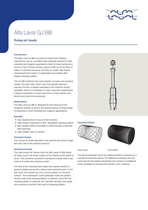
•Fast cleaning time in two to three minutes•High-impact cleaning in a 360° repeatable cleaning pattern •Slim design makes it possible to insert through small tank inlet openings•Light weight, easy to handleStandard designThe choice of nozzle diameters can optimize jet impact length and flow rate at the desired pressure.Working principleThe high-impact jet stream from the Alfa Laval GJ BB rotary jet head covers the entire surface of the interior of the barrel or drum. This achieves a powerful mechanical impact with a low volume of water and cleaning media.The flow of the cleaning fluid makes the nozzles perform a geared rotation around the vertical and horizontal axes. In the first cycle, the nozzles lay out a course pattern on the tank surface. The subsequent cycles gradually make the pattern denser until at full cleaning pattern is reached. Once the full cleaning pattern is reached, the machine will start over again and continue to perform the next full cleaning pattern.Cleaning PatternFirst Cycle Full PatternThe above drawings show the cleaning pattern achieved on a cylindrical horizontal vessel. The difference between the first cycle and the full pattern represents the number of additional cycles available to increase the density of the cleaning.TECHNICAL DATAMax. throw length:2.5 mRecommended pressure:5.5 - 55 barPHYSICAL DATAMax. ambient temperature:140 °CAvailable option:¾" NPT, ¾" BSPConceptAvoid hydraulic shock, hard and abrasive particles in the cleaning liquid, as this can cause increased wear and/or damage of internal mechanisms. In general, a filter in the supply line is recommended. Do not use for gas evacuation or air dispersion. For steaming we refer to the manual.Cleaning time6min5.554.543.532.520.450.550.650.750.850.95 1.051.151.251.35m /hInlet pressureA = Nozzle: 1.18 mm Stator 3.5B = Nozzle: 1.90 mm Stator 4.0C = Nozzle: 2.03 mmStator: 4.5D = Nozzle: 2.16 mm Stator: 5.0E = Nozzle: 2.16 mmStator: 5.5ABCDE4117-0074Flow Ratem3/h4117-0076A = Nozzle: 2.16 mmStator: 5.0 & 5.5B = Nozzle: 2.03 mm Stator 4.5C = Nozzle: 1.90 mmStator: 4.0D = Nozzle: 1.78 mm Stator 3.5Inlet pressure1.341.241.141.040.940.840.740.640.540.440.349141924293439444954barABCDImpact Throw Lengthcm295.4265.4235.4205.4175.4145.4115.485.455.425.491419242934Inlet pressureA = Nozzle: 2.16 mm Stator: 5.0 & 5.5B = Nozzle: 2.03 mm Stator 4.5C = Nozzle: 1.90 mmStator: 4.0D = Nozzle: 1.18 mm Stator 3.539444954barA B CD4117-0078Dimensions (mm)This document and its contents are subject to copyrights and other intellectual property rights owned by Alfa Laval Corporate AB. No part of this document may be copied, re-produced or transmitted in any form or by any means, or for any purpose, without Alfa Laval Corporate AB’s prior express written permission. Information and services provided in this document are made as a benefit and service to the user, and no representations or warranties are made about the accuracy or suitability of this information and these services for any purpose. All rights are reserved.200006877-1-EN-GB© Alfa Laval Corporate AB How to contact Alfa LavalUp-to-date Alfa Laval contact details for all countries are always availableon our website at 。
常用喷头全参数表格
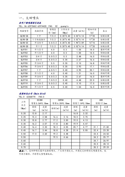
一、大田喷头余市广绿喷灌园艺设备TEL:06 62970652 62974420 FAX: 02 .guanglv.美国雨鸟公司(Rain Bird)TEL:0 62368770 FAX:01、这四种喷头属中远射程喷头,广泛用于固定式、半固定式和移动式喷灌系统,也可用于圆形、平移等大型喷灌机组。
2、30IBH——接口为3/4寸外螺纹,喷头仰角23o, 30PSH——接口为3/4寸外螺纹,喷头仰角27o, 46H——接口为3/4寸外螺纹,喷头仰角23o, 80E——接口为1.25寸外螺纹,喷头仰角27o。
3、历经60多年不断改进的摇臂撞击式驱动机构,工作稳定可靠,H型减磨密封垫,寿命长,副喷嘴采用低喷射仰角,弥补近处水量分布,均匀度高。
1、该类喷头上装有换向机构,通过调整换向机构,喷头可在20~340围的任意角度喷洒。
脱开换向机构,也可做全圆喷洒。
该类喷头适于布置在场地边缘。
2、历经60多年不断改进的摇臂撞击式驱动机构,工作稳定可靠;软——硬——软或软——硬型减磨密封垫,寿命长;独特的“雨鸟”式摇臂机构,动作灵活可靠。
3、2045PJ-08——接口为1/2寸外螺纹,喷头仰角23o, 35ATNT——接口为3/4寸外螺纹,喷头仰角27o, 65PJ——接口为1寸螺纹,喷头仰角27o, 85EHD——接口为1.25寸外螺纹,喷头仰角27o。
华维节水灌溉TEL:9 FAX:9锌合金摇臂式喷头(俗称锌鸟)配有换向机构,可以根据地块形状等调节喷洒围,将换向机构上翻,可作全圆喷洒,广泛用于园艺场、果菜园等开放式场所。
减磨密封垫,久经考验的撞击式驱动机构,锌铜合金材料,寿命长。
独特换向机构,动作灵活稳定,粉体烤漆,不掉漆,不褪色,可根据需要适当调节射程及液滴大小。
这两种喷头的接口尺寸为1/2寸外螺纹,喷头仰角23o。
万得凯节水技术TEL:8 32100346 FAX:4彩虹节水灌溉TEL:0 5975924 FAX:0371-975924ZY-1型摇臂式全圆喷头ZY-2型摇臂式全圆喷头备注:此规格喷头的接口尺寸为1寸螺纹。
喷淋说明书

喷淋杀菌隧道目录一、概述二、型号及名称三、技术指标四、主要结构与工作原理五、安装与调整六、操作、使用和维护七、附图一、概述本机是在吸收、消化国外样机的基础上全新设计而成,采用循环温水预热、循环热水杀菌、循环温水预冷,再用冷水喷淋冷却四段处理形成;具有杀菌温度自动控制、杀菌时间无级可调等优点,能广泛应用于各种瓶装、罐装酸性果汁饮料、电解质饮料、酒类、调味品等产品的杀菌冷却。
本机采用荷兰安运隆公司生产的聚丙烯网带,带面平整,摩擦系数小,可防止对三片罐、易拉罐底面的擦伤,网带符合食品卫生要求,并得到USDA认可,设备机架全部采用奥氏体不锈钢制造,外表美观、清洁、卫生。
二、型号及名称型号:JBPL-PLSJSD型名称:喷淋杀菌隧道三、技术指标最高杀菌温度: 80-95℃杀菌段宽度: 2000mm杀菌段长度: 5000mm(包括进输送带)预冷段长度: 1500mm冷却段长度: 2500mm(包括出输送带)输送网带线速度: 110-533mm/min加热蒸汽压力: 0.4Mpa设备总功率: 17KW设备外形尺寸(不包括进出输送带):9000×2800×16500mm(长×宽×高)设备净重: 3500kg四、主要结构与工作原理电动机经无级变速器、两级圆柱齿轮减速器带动蜗轮减速器,然后再用链条带动主动轴旋转,再由装在轴上的链轮带动网带移动,需杀菌的物料罐头(或瓶)由进料输送带送入,经塑料输送带过渡板进入网带上,并自动排列整齐进入预热区,循环水经加热后至预热工艺温度,由循环泵送至布置在网带上方的喷嘴内,被均匀雾化后淋洒在罐头(或瓶)上面对物料进行预热处理,温水再经网带流入温水槽循环使用。
经预热处理后的罐头(或瓶)进入杀菌区,循环水经蒸汽喷管加热至所需杀菌温度,由循环泵送至布置在网带上方的喷嘴内,被均匀雾化后淋洒在罐头(或瓶)上面对罐头进行加热杀菌。
然后热水经网带流入下部热水槽中,再被蒸汽重新加热至所需的杀菌温度,由泵抽出循环使用。
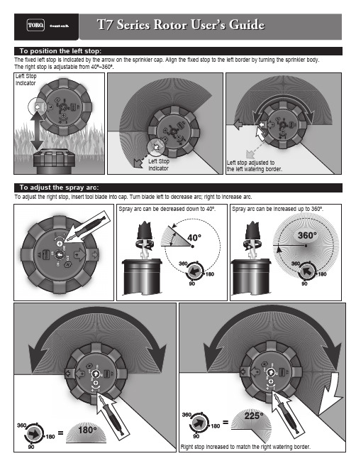
T7 系列喷头用户手册说明书
40
53.0
16.0
1.28
1.10
2,8
50
58
17.5
1.22
1.05
3,4
60
60
19.5
1.21
1.05
4,1
70
61
20.6 1.26
1.09
4,8
80
65
22.2
1.19
1.03
5,5
90
66
23.6
1.23
1.06
6,2
100
67
24.8
1.25
1.09
6,9
24.0
40
52
15.8
1.27
Pressure Bar
2,8 3,4 4,1 4,8 5,5 6,2 6,9
9.0
40
47
7.4
0.76
0.66
2,8
50
50
8.3
0.73
0.64
3.4
60
51
8.7
0.76
0.66
4,1
70
52
9.4
0.81
0.70
4,8
80
54
9.9
0.80
0.69
5,5
90
55
10.9
0.82
0.71
6,2
1.10
2,8
50
60
17.5
1.09
0.95
3,4
60
63
19.3
1.11
0.96
4,1
70
65
20.7
1.14
0.99
浴室洗浴用水墨喷洒设备说明书

After use fill the sprayer part way with water. Start the sprayer and allow clear water to be pumped through the plumbing system and out through the spray wand. Refill the tank about half full with plain water and use a chemical neutralizer such as Nutra-Sol® or equivalent and repeat cleaning instructions. Flush the entire sprayer with the neutralizing agent. Follow the chemical manufacturer’s disposal instructions of all wash or rinsing water.Drain all water and chemical out of sprayer, paying special attention to pump and valves. These items are especially prone to damage from chemicals and freezing weather. The sprayer should be winterized before storage by pumping a solution of RV antifreeze through the entire plumbing. Proper care and maintenance will prolong the life of the sprayer.Pump will not run:1. Check fuse next to the power switch. If blown or damaged replace with a new 5 Amp fuse.2. Insure the battery is fully charged3. Check that the on/off switch is in the on position4. Insure that strainer located on bottom of tank is free of debris.5. Insure there are NO kinks in the inlet/outlet hoses.This unit comes fully assembledThis sprayer is designed to be pulled or pushed by hand.Pour solution into the tank and stir to mix. For liquid chemicals it is possible to mix by spraying the handgun into the tank. Turn the switch to the “ON” position and spray by squeezing the lever on the handgun. The unit is supplied with ademand pump that will only operate while the lever on the handgun is depressed.It is recommended to charge the battery for 8-10 hours before using, or if the battery has been stored for 6 or more months without usage. Once fully charged you should be able to spray 40 gallons of fluid, or 8 consecutive tanks.To charge the battery…1. Plug the charger into a 110 Volt AC electrical receptacle.2. Insert the plug on the opposite end of the charger into the charging jack located on the back panel of the sprayer.3. Reverse the above steps when charging is complete.CAUTION: Never leave the charger connected to the battery for more the 20 hours, as this may damage the battery.The purpose of this manual is to assist you in assembling, operating and maintaining your sprayer. Please read it carefully as it furnishes information which will help you achieve years of dependable trouble-free operation.Workhorse products are warranted for one year from the date of purchase against manufacture or workmanship defects for personal or homeowner usage with proof of purchase. Work-horse products are warranted for 90 days for commercial users. Any unauthorized modification of a Workhorse brand sprayer will void warranty.Your authorized dealer is the best source of replacement parts and service. To obtain prompt, efficient service, always remember to give the following information:1. Correct part description and part number.2. Model number of your sprayer.Part description and part numbers can be obtained from the illustrated parts list section of this manual.Whenever you need parts or repair service, contact your distributor / dealer first. For warranty work always take your original sales slip, or other evidence of purchase date, to your distributor / dealer.Operation Precautions1.Do not operate pump in an explosive environment.Arcing from the motor brushes, switch or excessive heat from an improperly cycled motor may cause an explosion.2.3Do not assume fluid compatibility. If the fluid isimproperly matched to the pumps’ elastomers, a leak may occur.Do not pump gasoline or other flammable liquids.* Important return safety instructions:When you return your pump for warranty or repair,you must always do the following:1.Flush chemical residue from the unit2.Tag unit with type of chemicals having been sprayed.3.Include complete description of operation problem,such as how unit was used, symptoms of malfunction, etc. Since unit can contain residues of toxic chemicalsthese steps are necessary to protect all the people who handle return shipments, and to help pinpoint the reason for the breakdown.WORKHORSE SPRAYERS ®, a division of Green Leaf, Inc. 9490 N BALDWIN ST FONTANET, IN 47851 888-433-6631P A R T S L I S TD E S C R I P T I O NP A R T #Q T Y I T E M B 3400 P60013911P i n c h C l a m p60014942#8x 3/4 T E K S c r e w60019943B a c k P a n e l61000214R e t r a c t a b l e H a n d l e A s s y .610006151/4" S u c t i o n H o s e61001116E c o n o m y W a n d A s s e m b l y61001217W 40661002318E L 14Q D61002429C 1400 C P610026110W i r e K i t A s s e m b l y610033111L i t h i u m B a t t e r y P a c k610039112F o a m B a t t e r y A d a p t e r6100401131.0 G P M Q A P u m p640454114L i t h i u m I o n B a t t e r y C h a r g e r610041115** - N o t S h o w nW O R K H O R S E S P R A Y E R S ®, a d i v i s i o n o f G r e e n L e a f , I n c . 9490 N B A L D W I N S T F O N T A N E T , I N 47851 w w w .w o r k h o r s e s p r a y e r s .c o m 888-433-6631P a r t s L i s tD E S C R I P T I O NP A R T N U M B E R Q T Y I T E M 5 G a l l o n T a n k 610000115 G a l l o n T a n k L i d 61000112B a c k P a n e l 61000213C h a r g e r P a n e l D o o r 61000314φ3/8" A x e l M o u n t i n g B r a c k e t61000525W h e e l 61000426φ3/8" x 14 7/8" A x e l 61001317φ3/8 C a p N u t B l a c k610019281/4-20 x 1/2" P a n H e a d S c r e w 61001769W a n d C l i p 600151210W a n d C l i p S c r e w600152211 05/21W O R K H O R S E S P R A Y E R S ®, a d i v i s i o n o f G r e e n L e a f , I n c . 9490 N B A L D W I N S T F O N T A N E T , I N 47851 w w w .w o r k h o r s e s p r a y e r s .c o m 888-433-6631— 5 GALLON SPOT SPRAYER —MODEL # LG 05 SS•5 Gallon Polyethylene Tank •1.0 GPM Demand Pump •Lever Handgun•Rechargeable 12V Battery •AC Charger w/built in Storage Compartment•Telescoping Handle •Large 8 Inch WheelsLG 05 SS5 gal. 12V RechargeableSprayerWORKHORSES P R A Y E R Sa Division of Green Leaf, Inc®WORKHORSE SPRAYERS ®, a division of Green Leaf, Inc. 9490 N BALDWIN ST FONTANET, IN 47851 888-433-6631。
紧急洗手液喷嘴说明书

Scan forInformationP roduct o verview40 fl. oz. (1.2 L) capacity soap dispenser in Matte Black Powder Coated Stainless Steel comes with an all purpose valve and a tamper-resistant refill indicator. Push button to dispense soap. Unit is refilled through hinged door at top requiring special key (supplied) to open. Soap tank will continue to feed properly until soap level is below valve intake port. Requirements: Proper usage of this dispenser requires, that only soap within the following range for viscosity and pH may be used. American Specialties, Inc. | 441 Saw Mill River Road, Yonkers, NY 10701 | (914) 476-9000 | Model:#0347-41Issued:11/1/2021Revised:3/10/2023Page:1 of 2Revision :R1S uStainability /lEEDSoap Dispenser (Liquid) Vertical – Matte Black Powder Coated Stainless Steel – Surface MountedToilet Accessories CSI:10 28 13MR 4.1 (1)MR 4.2 (1)MR 6 (1)EQ 4.1 (1)EQ 4.2 (1)EQ 4.4 (1)51O peratiOn & M aintenance t echnical i nfOrMatiOn / p rOduct p rOpertiesi nstallatiOnW arrantyT echnical Data SheetUnit is surface mounted to wall or partition with a wall mounting plate (supplied) and screws (by others). Unit is secured to interlocking wedge bracket and locked in place by a locking screw (supplied) installed through hinged refill door. Recommended installation for general utility is 42" [1066] Above Finished Floor (AFF) or 6" [152] min above washbasin. For compliance with 2010 ADA Accessibility Standards and 2015 ABA Standards, install unit with centerline of valve button no higher than 48" [1219] AFF .Manufacturer reserves the right to make changes to the design, dimensions or functionality of the product without formal notice.Push button to dispense soap. Unit is refilled through hinged door at top requiring special key (supplied) to open. Soap tank will continue to feed properly until soap level is below valve intake port. T ank supply is replenished manually on cycle determined by maintenance needs.One (1) Y ear from date of invoiceAmerican Specialties, Inc. | 441 Saw Mill River Road, Yonkers, NY 10701 | (914) 476-9000 | Model:CSI:#0347-4110 28 13Toilet Accessories Issued:11/1/2021Revised:3/10/2023Page:Revision :Type 304 Stainless Steel - Matte Black Powder Coated N/APropertyValue DimensionsConstruction4-13/16" x 8-3/16" x 3-15/16" [122 x 208 x 100] Spout projection: 3/4" [19]Surface Mounted2 of 2R1Mounting Options。
常用喷头参数表
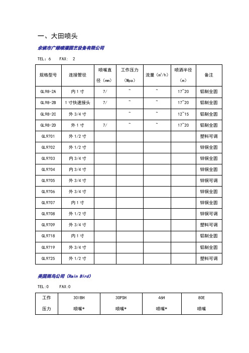
一、大田喷头余姚市广绿喷灌园艺设备有限公司TEL:6 FAX: 2美国雨鸟公司(Rain Bird)TEL:0 FAX:0备注:1、这四种喷头属中远射程喷头,广泛用于固定式、半固定式和移动式喷灌系统,也可用于圆形、平移等大型喷灌机组。
2、30IBH——接口为3/4寸外螺纹,喷头仰角23o, 30PSH——接口为3/4寸外螺纹,喷头仰角27o, 46H——接口为3/4寸外螺纹,喷头仰角23o, 80E——接口为寸外螺纹,喷头仰角27o。
3、历经60多年不断改进的摇臂撞击式驱动机构,工作稳定可靠,H型减磨密封垫,寿命长,副喷嘴采用低喷射仰角,弥补近处水量分布,均匀度高。
备注:1、该类喷头上装有换向机构,通过调整换向机构,喷头可在20o~340o范围内的任意角度内喷洒。
脱开换向机构,也可做全圆喷洒。
该类喷头适于布置在场地边缘。
2、历经60多年不断改进的摇臂撞击式驱动机构,工作稳定可靠;软——硬——软或软——硬型减磨密封垫,寿命长;独特的“雨鸟”式摇臂机构,动作灵活可靠。
3、2045PJ-08——接口为1/2寸外螺纹,喷头仰角23o, 35ATNT——接口为3/4寸外螺纹,喷头仰角27o, 65PJ——接口为1寸内螺纹,喷头仰角27o, 85EHD——接口为寸外螺纹,喷头仰角27o。
上海华维节水灌溉有限公司TEL:FAX:锌合金摇臂式喷头(俗称锌鸟)配有换向机构,可以根据地块形状等调节喷洒范围,将换向机构上翻,可作全圆喷洒,广泛用于园艺场、果菜园等开放式场所。
减磨密封垫,久经考验的撞击式驱动机构,锌铜合金材料,寿命长。
独特换向机构,动作灵活稳定,粉体烤漆,不掉漆,不褪色,可根据需要适当调节射程及液滴大小。
这两种喷头的接口尺寸为1/2寸外螺纹,喷头仰角23o。
上海万得凯节水技术有限公司TEL: FAX:备注:这两种喷头的接口尺寸为1/2寸外螺纹,喷头仰角23o。
河南彩虹节水灌溉有限公司TEL: 5975924 FAX:0371-975924ZY-1型摇臂式全圆喷头ZY-2型摇臂式全圆喷头备注:此规格喷头的接口尺寸为1寸内螺纹。
常用喷头参数表
一、大田喷头余娣市广绿嗖酒国艺按»有限公司美国甬鸟公司(Rain Bird)备注八、迪呱种喷头属中远射桿険头,广泛用于固定衣、半固定貳和移动貳喷灌系统,也可用于風形、平務等夫型険灌机组。
2、30IBH——接口为3/4寸外螺纹,喷头W角23。
,30PSH——接口为3/4寸外嗓纹,喷头仰角27°, 46H—-接口为3/4寸外螺纹,咳头仰角23°, 80E——接口» 1.25寸外",« 头H角27%3、师经60多年不斷改进的摇臂撞击貳驰动机构,工作稳定可靠,H里凰曆密封垫,寿命长,副陵嘴采用低喷射Wft,祢补近处朮量分布,均匀度高。
备庄八、该类喷头上芸有换向机枸,通过阔整换向机构,喷头可在20^340°范围内的任恿角度内険洒。
肮开换向机构,也可做全网喷酒。
该类瞰头适于布置在场地边缘。
2、历经60多年不Mftjfi的摇臂撞击氏驰动机构,工作梯定可靠;«一硬一軟或软一硬塑資曆密封垫,寿命长;奴特的“甬鸟”式摇臂机构,动作灵活可靠。
3、2045PJ-08——接口力1/2寸外嗓纹,除头伸角23°, 35ATNT——接口为3/4寸外螺奴, 瞼头仰甬27°, 65PJ——接口为1寸内螺级,喷头仰角27°, 85EHD——接口力1.25寸外螺奴,虞头W角27°0上海华维节水濃溝有眼公司TEL: 9 FAX: 9锌台金摇臂直嚴头(浴称锌鸟)配有换向机构,可以根据地挟形状等调节陵洒范围,將换向机构上翻,可作全岡照前,广泛用干皿艺场、果菜园等开故氏场两。
凰曆密MS,久经考验的撞击式驱动机构,锌审合金MM,青命长。
视待换向机构,別作灵活稳定,粉体烤漆, 不掉漆,不褪色,可根齬需要适当嗚节射程及液询大小。
2Hft«头的接口尺寸为1/2寸外螺纹,眦头仰角23°。
上通万得罠节水技术有眼公司i1/223°河南彩更节水濯淡有限公司TEL: 0 5975924 FAX: 0371-975924ZY-1型摇臂式全Bl喷头ZY-2型摇臂式全圓喷头备注:utsfina头的接口尺寸为1寸内噪纹。
- 1、下载文档前请自行甄别文档内容的完整性,平台不提供额外的编辑、内容补充、找答案等附加服务。
- 2、"仅部分预览"的文档,不可在线预览部分如存在完整性等问题,可反馈申请退款(可完整预览的文档不适用该条件!)。
- 3、如文档侵犯您的权益,请联系客服反馈,我们会尽快为您处理(人工客服工作时间:9:00-18:30)。
目录
概 述 .........................................................................................................................................................................1
双孔水针系列 ..............................................................................................................................................................3 单孔水针系列 ..............................................................................................................................................................4 裁纸边喷嘴系列 ..........................................................................................................................................................6 片式针形喷嘴系列 ......................................................................................................................................................7 针形喷嘴系列 ..............................................................................................................................................................8 干网清洗喷嘴系列 ....................................................................................................................................................13 针孔针形喷嘴系列 ....................................................................................................................................................14 自清洗喷嘴系列 ........................................................................................................................................................15 片式扇形喷嘴系列 ....................................................................................................................................................16 钮扣式扇形喷嘴系列 ................................................................................................................................................17 扇形喷嘴系列 ............................................................................................................................................................18 蒸汽喷嘴系列 ............................................................................................................................................................26 球阀体剥浆喷嘴系列 ................................................................................................................................................27 定边扇形喷嘴系列 ....................................................................................................................................................28 扇形喷嘴系列 ............................................................................................................................................................29 淀粉喷嘴系列 ............................................................................................................................................................31 微细雾化喷嘴系列 ....................................................................................................................................................32 高热干燥喷嘴系列 ....................................................................................................................................................34 消泡喷嘴系列 ............................................................................................................................................................35 空气喷嘴系列 ............................................................................................................................................................41 洗管喷嘴系列 ..............................................................................................................................................................44 旋转喷嘴系列 ..............................................................................................................................................................45 洗罐喷嘴系列 ..............................................................................................................................................................46 方形喷嘴系列 ..............................................................................................................................................................47 黑液喷嘴系列 ..............................................................................................................................................................48 除尘喷嘴系列 ..............................................................................................................................................................49 淬火喷嘴系列 ..............................................................................................................................................................50 环保漂淋喷嘴系列 ......................................................................................................................................................53 脱硫除尘喷嘴系列 ......................................................................................................................................................54 吹气喷嘴系列 ..............................................................................................................................................................55 园林喷嘴系列 ..............................................................................................................................................................57 纺织喷嘴系列 ..............................................................................................................................................................58 钢铁喷嘴系列 ..............................................................................................................................................................59 油枪喷嘴系列 ..............................................................................................................................................................60 附 件 ..........................................................................................................................................................................61
