03 KMX15R控制阀说明书
2009挖掘机维修资料

挖掘机维修资料EX 系列EX220 服务手册 71.2MB EX300-3 T140E-00 first part 12.6MB EX220 基本配件目录 20.6MB EX300-3 T140E-00 latter part 11.5MB EX220 内部配件目录 11.7MBEX300-3 W140E-00 first part 21.6MB EX300-2,EX300LCH-2 内部配件目录 4.94MB EX300-3 W140E-00 latter part 11.3MB EX300-2 操作人员手册 10.5MB EX300-3 操作人员手册 11.8MB EX300-2 服务手册 74.8MB EX300-3 技术手册 20.4MB EX300-2 基本配件目录 20.3MB EX300-3 装修手册 37.3MB EX300-2 技术手册T110-01 13.8MB EX300-3内部配件目录 5.22MB EX300-2 装修手册W110-01 18.7MBEX300LC-3基本配件目录 28MBSUPER LONG DEMOLITION FRONT APPLICABLE AND EXCLUSIVE TO EX300LC-2 HYDRALIC EXCA V ATOR (S-HL300-3 T 2.31MBSUPER LONG DEMOLITION FRONT APPLICABLE AND EXCLUSIVE TO EX300LC-5,EX350LCK-5 HYDRALIC EXCA V ATOR 2.04MBEX300-3C,EX310LCH-3C 操作人员手册 14.6MB EX300-5-370HD-5内部配件目录(P1H1-E1-3) 7.15MB EX300-3C 操作原理TO140C-01 8.68MB EX300-5(W)ALL 装修手册 23.4MBEX300-3C 故障诊断TT140C-01 3.4MB EX300-5,EX300LC-5,EX350H-5,EX350LCH-5,EX370H D-5 操作人员手册 10.7MBEX300-3C 内部配件目录 4.48MB EX300-5,EX350LCK-5,EX370HD- 基本配件目录(P1H1-1-1) 30.3MBEX300-3C 装修手册 27MBEX300-5技术手册(操作原理) 2.28MB EX300 310H-3C 基本配件目录 30.6MB EX300-5技术手册(故障诊断) 3.88MB EX300-5HHE 技术手册(操作原理) 4.94MB EX300_370-5操作人员手册 10.7MB EX300-5HHE 技术手册(故障诊断) 7.28MB EX300-3HHE 操作人员手册 6.47MB EX300-5HHE 装修手册 17.4MB EX300-3HHE 技术手册(合肥日立) 12.1MB EX300-5HHE 零件图册 15.6MB EX300-3HHE 装修手册 19.5MB EX300-5HHE 零件图册(液压件) 2.94MB EX300-3零件册(液压件) 7.40MB EX300LC 基本配件目录 22.4MB EX300-3零件手册 12.1MBEX300LC 内部配件目录 10.2MB EX400-3, EX400-3C CONTENTS 32.4KB EX300服务手册 50MBEX400-3, EX400-3C TM 12.1MB EX330LC-5,370-5服务手册 32.6MB EX400-3, EX400-3C WM 15.7MBEX350LC-5HHE 技术手册(操作原理) 5.37MB EX400-5, EX400LC-5, EX450LC-5 CONTENTS 32.6KB EX350LC-5HHE 零件图册 19.8MBEX400-5, EX400LC-5, EX450LC-5 TM 7.83MBEX350LC-5HHE 零件图册(液压件) 2.9MB EX750-5 Cold District 基本配件目录(RP17C-OP8-1)862KBEX350LC-5HHE 装修手册 17.9MB EX750-5 Paperdrain Specifications 基本配件目录(P17C-OP7-1) 754KB EX350LC-5技术手册(故障诊断) 7.44MB EX750-5 电气图 1.2MBEX350LC 操作人员手册 10.2MB EX750-5 技术手册 (操作原理) 8.89MB EX1100-3 技术手册 (操作原理) 9.88MB EX750-5 技术手册(故障诊断) 12.8MB EX1100-3 技术手册(故障诊断) 12.1MBEX750-5 装修手册 25MBEX1100-3 装修手册 31.6MB EX750-5,EX800H-5 基本配件目录(P17C-1-1) 16.9MBEX1100-3操作人员手册 15.1MB EX750-5,EX800H-5 Auto-Librication System基本配件目录(P17C-OP1-1) 3.91MBEX1100-3基本配件目录(P17E-1-1) 26.1MB EX750-5,EX800H-5 基本配件目录(P17C-1-2) 28.6MBEX1100-3内部配件目录(P17E-E1-1) 7.97MB EX750-5,EX800H-5内部配件目录(P17C-E1-3)13.9MBEX1200-5操作人员手册 15.5MB EX750,800-5使用说明书 519KBEX1200-5故障诊断 3.62MB EX1200-5D Cold-Resistant Type Parts Catalog 3.92MBEX1200-5基本配件目录(P17F-1-1) 8.03MB EX1200-5D Quarry Specifications(Q.S) Parts Catalog 2.76MB EX1200-5技术手册(操作原理) 2.72MB EX1200-5D 技术手册(操作原理) 6.51MBEX1200-5内部配件目录(P17F-E2-4) 8.97MB EX1200-5D 技术手册(故障诊断) 11.7MBEX1200-5装修手册 5.33MB EX1200-5D 装修手册 10MBEX1200-5C操作人员手册 11.9MB EX1200-5D操作人员手册 14.6MBEX1200-5C基本配件目录 22.7MB EX1200-5D基本配件目录(P18F-1-1) 19.1MBEX1200-5C内部配件目录 4.76MB EX1200-5D内部配件目录(P18F-E1-1) 6.4MBEX1200-5C液压设备操作装修手册 7.25MB EX200 Rolling Shovel Parts Catalog 8.7MBEX1800-2 Backhoe Front Boom 8.M ARM 3.6M Parts Catalog 3.46MB EX1800,EX3500 MECHATRO ANALYZER (HS801) 3.31MBEX1800-2 OPTIONAL Parts Catalog 4.26MB EX1800基本配件目录 27.3MBEX1800-2操作人员手册 10.6MB EX1800内部配件目录 11.6MBEX1800-2服务手册 35.1MB EX1900-5(操作原理) 5.6MBEX1800-2基本配件目录(P182-3-1) 26.8MB EX1900-5(故障诊断) 19.1MBEX1800-2内部配件目录(P182-E3-1) 15.2MB EX1900-5(装修手册) 13MBEX1800-3故障诊断 12.7MB EX1900-5操作人员手册 4.99MBEX1800-3基本配件目录(P187-1-1) 25.5MB EX1900-5基本配件目录 26MBEX1800-3技术手册(操作原理) 8.82MB EX1900-5内部配件目录 6.91MBEX1800-3内部配件目录(P187-E1-1) 10.3MBEX1800-3装修手册 16.9MBKATO加藤HD700-7--2电脑板 17.8MB HD820-2配件目录(1) 4.42MBHD800VII液压回路图 717KB HD820-2配件目录(2) 12.8MBHD820-2 APC100服务手册(清晰版) 7.5MB HD820-2液压图 1.18MBHD820-2 APC100故障代码信息 109KB HD820服务手册 9.69MBVOLOV沃尔沃ATLAS阿特拉斯—特雷克斯1604LC 液压系统调试 87MB 2306LC操作维修手册(完成版) 13.9MB1604LC_Workshop_manual 56.5MB 2606LC操作维护手册(1704) 188MB1604调试程序 10.4MB 3306LC操作维修手册交印版(1804) 547MB 1804调试工作 21.7MB ATLAS液压挖掘机电器简介2306 17.6MB 2012发动机操作手册 5.28MB ATLAS液压挖掘机电器简介3306 26.4MB CASE凯斯CX210--CX240维修手册 50.8MB CX330维修手册 18.6MbCASE凯斯保养 13MB SEPAR 2000 506KBConstruction Equipment Service Training 3.32MB 电磁阀图示 356KBCX75X-3--SERVICE TEXT 18MB 防盗资料 2.43MBCX210-240挖掘机维修手册A 18.6MB 机具加固 2.27MBCX210-240挖掘机维修手册B 75.1MB 凯斯24气门发动机 106MBCX210,240维护手册 8.36MB 凯斯用户培训 113MBVOLOV沃尔沃EC55B维修资料 41.4MB EC700B CD维修资料 72.7MBEC140B维修资料 59.9MB EW170维修资料 6.63MBEC210B Training CD 364MB VCE Training 2005维修资料 27.6MBEC240-290B维修资料 217MB William 137MbEC360B维修资料 81.5MB 培训1 74.5MBEC460B Training CD 244MB 培训2 138MB大宇V 型机操作与保养视频 519MB DH220-7 零件目录 10.1MB电路液压图 33.6MB DH220LC-V 电气系统 1.91MB大宇故障维修事例(05 年版) 2.31MB DH225LC-7 主要功能改进介绍 4.91MB7 型挖掘机培训教材 55.3MB 2005 大宇V-MODEL 电气培训教材(上) 18.2MB 大宇7-MODEL 液压电气培训教材 13.7MB 大宇V-MODEL 电气培训教材(下) 41.2MB大宇DH-5 系列-电气教材 73.7MB 2003 技术信息 1.86MB卡特彼勒200B维修资料 22.6MB 320D维修资料 6.37MB305CR维修资料 24.7MB 324D&325D维修资料 23.9MB312B电路图及液压图维修资料 781KB 325B维修资料 34.8MB320B维修资料 96.8MB 325C维修资料 42.3MB320C维修资料 378MB 330C维修资料 74.3MBCAT320C 挖机五个技术技巧 5.06MB 330D维修资料 2.65MB320C ELECTINOIC电路图 603KB ACERT Engine C7-C32 67MB320C- Hydraulic Schematic 2.25MB C系列机液压KIT 22.4MB320C-E电气系统图GPS监控 16.5MB320C简介 4.95MB STW维修服务系统 21.1MB320C挖掘机操作员技能培训教材(利星行) 13MB 卡特彼勒学习管理系统(CLMS) 1.85MBCAT320C 3064与3066发动机SCNR5546-03-01-ALL 6.27M客户售后服务协议(CSA) 34.1MBCAT320C U电路图-APA.CLM.ALX.CLZ 1.10MB 破碎锤Hammer for HEX 37.7MBCAT320C电路图-HBC.GHA 583KB 设备工具服务光盘 57.7MBCAT320C电路图-MAB.PAB.GAC.FBC.SBN.RAW 604K 新产品引进(NPI)服务培训CAT320C测试与调整液压系统RCNR3817-00-01-ALL 10.4M CAT320C-AKH主泵 1.74MBCAT320C发动机与泵控制系统RCNR3814-00-01-ALL 21.1M CAT320C-AKH主控制阀 772KBCAT320C系统运行(液压系统)RCNR3816-01-01-ALL26.1K CAT320C-BDB电路图 1.84MBCAT320C液压图RCNR3816-01-01-INS 6.54MB CAT320C-BDB液压图 2.25MBCAT320C操作保养视频 271MB CAT320C-PAC电路图 591KBCAT新产品引进(NPI)服务培训 277MB利勃海尔LIEBHERR-942HD零件手册 9.33MB LIEBHERR液压系统祥解 5.28MB柳工2007年柳工挖掘机总体培训资料 174MB C系列销售文件(新) 65.9MB2007年挖机培训资料 41.3MB ITM四轮一带 4.90MBCLG200-3、230销售文件 409MB 川崎液压件 12.9MBCLG200-3czsc 3.59MB 各机型液压破碎锤装配图 791KBCLG200-3ljtc 9.24MB 柳工公司文件 99.4MBCLG907零件图册(05年部分) 3.46MB 柳工挖机培训资料 117MBCLG907最新资料11.3MB 柳工挖机液压原理图 10.3MBC系列比例电磁阀图 1.13MB 柳工主液压部件的解剖图 29.9MBC系列驾驶室零件图册(05-9) 1.21MB 05柳工液压挖掘机的检测维修 5.13MB日立ZX27-30-35维修技术服务手册 37.4MB ZX200,270-3维修技术服务手册 266MBZX27,30,35U-2维修技术服务手册 14.1MB ZX210W-3,220W-3维修技术服务手册 84.2MBZX40-55维修技术服务手册 81MB ZX210W维修技术服务手册 89.1MBZX40,50U-2维修技术服务手册 58.1MB ZX330-3,350LCN-3,360LC-3维修技术服务手册127MB ZX60维修技术服务手册 54.5MB ZX330-370维修技术服务手册 100MBZX70维修技术服务手册 70.5MB ZX450-3,520LC-3维修技术服务手册 146MBZX110-120维修技术服务手册 73.9MB ZX450H 维修技术服务手册 80.5MBZX130W维修技术服务手册 85.1MB ZX600,650配件手册 16.7MBZX140W-3维修技术服务手册 97.8MB 日立视频系列维修资料 1.31GBZX160W维修技术服务手册 114MB 日立小大夫软件 65.6MBZX170W,190W-3维修技术服务手册 117MB 卫星安装要领书 1.66MBZX180W维修技术服务手册 70.5MB 系统图 101MBZX200-270维修技术服务手册 134MB三一重工iB油圧回路図 68KB 挖掘机培训教材-液压挖掘机结构及使用 24.4MbSY60(70)售后课件(液压)--胡奇 4.85MB 液压泵及其控制系统 9.36MBSY60挖掘机电气控制系统 314KB 液压泵进油压力对工程机械考能的影响 60.5KBSY200C1挖掘机电气控制系统培训教材 5.87MB 液压挖掘机的检查、调整和维护 41.5KBSY310挖掘机电气控制系统培训教材 1.87MB 液压挖掘机讲座二 1.23MB三一挖掘机特点 23.5KB 液压挖掘机讲座三 1.29MB三一挖掘机液压系统 2.79MB 液压挖掘机讲座一 632KB三一液压挖掘机培训教材(刘军士) 23MBSK35SR-3维修培训资料 4.91MB SK-6液压挖掘机维修培训资料 910MBSK55维修培训资料 1.59MB 200-6E高级培训 50.7MBSK100-2轮式维修培训资料14.5MB SK230,250-6机械手册 57.9MBSK200-1维修培训资料 47.4MB 6E电气原理图-1-2-3 6.9MB电路图 11MB SK-6液压电气图 1.69MBKMX15R控制阀说明书 2.14MB SK-6液压电气系统-目录 197KBSK200-1(黄色)零件手册 8.06MB SK-6液压电气系统研修资料-正文 62MB神钢国际机型挖掘机多路控制阀柄4.33<B KOBELCO 6型机液压挖掘机高级点检 7.04MB 神刚-总成吊装2 91.1MB KOBELCO SK200-6E部分零件图 1.2MB神钢液压电气基础-1-5册 246MB KOBELCO SK200-6E空调系统 11.8MB神钢SK200-6液压电气培训资料(网络版)KOBELCO SK320-6E引擎电子系统(2005年6月修订版) 12.4MB神钢液压挖掘机高级点检1-2 44.2MB KOBELCO-SK230(LC)-6E装修手册 9.79MB神钢-总成吊装3 80.7MB SK200-6E操作维护研修教材1-20,2-34 7.16MB 神钢-总成吊装4 62.4MB SK200-6E操作维护研修教材4-50页 5.94MB液压电气图 505KB SK200-6E操作维护研修教材5-11 1MBSK-8系列新液压挖掘机维修培训资料 1.2GB SK200-6E操作维护研修教材6-1-8-1 2.39MB 调整视频 921MB SK200-6高级点检,正文 4.48MB日野发动机 107MB SK200-6型挖掘机液压和电控系统方框图 233KB 日野发动机故障诊断2006-8-14 24MB SK200-6型挖掘机液压系统原理图 761KB日野发动机研修教材2006-8-14 25.8MB SK200-6液压电气系统-目录 307KB新机型相关教材编辑说明(2006-8-14) 386KB SK200-6液压电气系统-正文 11.6MBSK200-8产品销售培训 31.8MB SK200&230-6E售后服务研修教材 6.26MBSK200,330-8服务研修教材2006-8-14 18.1MB SK200&230-6E售后服务研修教材-内容 2.26MB SK330-8服务研究教材 13.1MB SK230 250-6机械手册 49.3MBSK330-8结构和功能 6.3MB 神刚挖掘机维修手册(上) 9.3MB神刚挖掘机维修手册(下) 24.3MB神刚挖掘机维修手册(序) 5.29MB神刚挖掘机维修手册(中) 11.3MB神刚液压系统原理图SK200-6E-Model 190KB石川岛IHI-技术资料-JP 59.5MB 80NX 维修讲义 3.52MB35NX油圧回路 359KB 80NX電気 149KB45-55N 5.26MB 80NX油圧回路 447KB55N Parts manual 24.2MB IHI技术培训05 7.85MB55N 電気 126KB TNV洋马维修讲义 5.45MB55N油圧回路 402KB 給油脂、定期交換 293KB80NX 4.82MBR55-3维修培训资料 70.2MB 现代(江苏)技术变更通报 10.3MBR55-7维修培训资料 59.8MB 现代发动机资料 44MBR60-5维修培训资料 58.5MB 现代系列机零件目录 941MBR80-7维修培训资料 27MB R55-5零件图册(267P) 77.3MBR250LC-7维修培训资料 32.1MB R130LC-5(226P)零件图册 68.2MBR260LC-7维修培训资料 21MB R200-5(193P)零件图册 42.1MBR290LC-3维修培训资料 26.8MB R200W-5(376P)零件图册 85MBR290LC-7维修培训资料 37.8MB R205-7(253P)零件图册 67.7MBR305LC-7维修培训资料 17.3MB R210-5(205P)零件图册 45.1MBR320LC-7维修培训资料 36.2MB R215-7(255P)零件图册 67.6MBR360LC-7维修培训资料 33.7MB R220LC-5(486P)零件图册 81.6MBR450LC-7维修培训资料 43.3MB R220LC-7(323P)零件图册 79.1MBR500LC-7A维修培训资料 19.4MB R225LC-7零件图册 17.8MB部分电路液压图 16MB R260LC-5(355P)零件图册 81.6MB6 现代挖掘机电气系统(245-278) 10.7MB R300LC-5(468P)零件图册 88.3MB7 电气系统主要功能综述(279-288)2.43MB R305LC-7(304P)零件图册 71.6MB-7系列机服务指南 23.5MB R335LC-7(297P)零件图册 68.2MB9 主要机型电气回路图(311-344) 4.81MBR210LC-7维修手册 10.6MBR220-5故障代码诊断 167KB现代装修手册-5型 10.5MB主控阀管路 35KB小松komtrax全球定位系统 15MB PC270-7 101MBPC30 50MR-2 142MB PC300-6 238MBPC60-7 29.4MB PC300,400-5 7.54MBPC130-7 48.6MB PC300,350,360-7 163MBPC200-5 94.2MB PC750,800-7 111MBPC200-6 506MB 内部故障案例 27.6MBPC200-7 388MB 小松发动机 140MBPC200-8 390MB 小松内部培训资料 502MBPC228US-2 8.51MB住友发动机诊断 1.9MB 住友200,300EC电机的简单测量法 24KB服务技术信息11.1MB 住友200A1A2技术服务手册(电气篇) 128MB 五十铃发动机装配图片6HK1 142MB 住友A1-A2=2电路图 0.99MB住友中俊服务培训资料 14.7MB 住友PAX性能测试过程视频 271MBSH200-2服务手册(故障诊断系统) 1.87MB 住友PAX性能测试过程视频 272MBSH200-3零件手册 89.9MB 住友SH200-3液压电气技术服务手册 6.47MB SH200-3维护手册(电气线路篇) 17.6MB 住友SH200(220)-3电器系统原理 45.3MBSH200-3维护手册(电气线路篇) 13.9MB 住友SH200A3维护手册 29.5MBSH200-3维护手册(概述篇) 10.4MB 住友SH-A系列故障诊断 24KBSH200-3维护手册(维护篇) 8.74MB 住友调电脑 24KBSH200-3维护手册(液压油路篇) 24MB SH450LHD,SH300-2维修手册 339MBSH200-3维护手册(主体篇) 2.94MB 中俊住友-3电气系统原理讲座视频608MB SH200GT-3维修手册(完全篇) 13.9MB。
挖掘机维修资料大全PPT课件
.
14
手册住友SH-A系列故障诊断住友调电脑 神刚 11 SK35SR-3SK55SK100-2轮式SK200-1SK-6机SK-8 系列新机电路图A3KMX15R控制阀说明书SK200-1(黄 色)零件手册
.
15
神钢国际机型挖掘机多路控制阀 卡特彼勒 20200B305CR312B320B320C320D324D&325D325B325 C330C330DACERT Eห้องสมุดไป่ตู้gine C7-C32C系列机液压KI
.
6
6PC300,400-5PC300,350,360-7PC400-6,4506PC600-7PC650-5SEPC750,800-7PC1250-7内部故障案 例小松发动机小松内部培训资料 EX系列
.
7
35EX30UR-2EX60EX100-2,120-2EX120-3EX1205EX125WD-5EX200-2EX200-3EX200-5EX2005HHEEX200LCEX220-2EX22
.
8
0-3EX220,230-5HHEEX220LCEX300-2EX300-3EX3003CEX300-3HHEEX300-5EX300-5HHEEX300LCEX330LC5EX350LC-5HH
.
9
EEX400-3EX400-5EX750-5EX1100-3EX1200-5EX12005CEX1200-5DEX1800EX1800-2EX1800-3EX1900-5 住友31SH100,12
.
.
2
0W服务手册ZX330-3,350LCN-3,360LC-3服务手册 ZX330-370服务手册ZX450-3,520LC-3服务手册 ZX450H 服务手册ZX600,650配件手册ZX800,850H
3寸流体控制阀门说明书

Product Features50 psi bubble tight shut-off, Long stem design allows for 2” insulation, Valveface-to-face dimensions comply with API 609 & MSS-SP-67, Completelyassembled and tested, ready for installation, Tees comply with ASME/ANSIB16.1 Class 125 flangesApplicationThese valves are designed to meet the needs of HVAC and commercialapplications requiring bubble tight shut-off for liquids. Typical applicationsinclude chiller insolation, cooling tower isolation, change-over systems, largeair handler coil control, bypass and process control applications. The largeCv values provide for an economical control valve solution for larger flowapplications. Designed for use in Victaulic piping systems.Jobsite NoteValves should be stored in a weather protected area prior to construction.Complete installation recommendations can be found in Belimo’s Installationand Maintenance Instructions for F6/F7… Butterfly Valves.Application NotesThese valves are designed to meet the needs of HVAC and commercialapplications requiring 0% leakage for liquids. Typical applications include chillerisolation, cooling tower isolation, change-over systems, large air handler coilcontrol, bypass and process control applications. The large Cv values providefor an economical control valve solution for larger flow applications. Designedfor use in ANSI flanged piping systems.F780HDU, 3-Way Butterfly ValveResilient Seat, 304 Stainless Steel DiscDatecreated,7/1/216-Subjecttochange.©BelimoAircontrols(USA),Inc.F780HDU, 3-Way Butterfly Valve Resilient Seat, 304 Stainless Steel DiscDatecreated,7/1/216-Subjecttochange.©BelimoAircontrols(USA),Inc.†Rated Impulse Voltage 800V, Type action 1, Control Pollution Degree 3.GMX24-MFT-X1Modulating, Non-Spring Return, 24 V, Multi-Function Technology®D a t e c r e a t e d , 07/10/2016 - S u b j e c t t o c h a n g e . © B e l i m o A i r c o n t r o l s (U S A ), I n c .AActuators with appliance cables are numbered.Provide overload protection and disconnect as required.Actuators may also be powered by 24 VDC.Only connect common to negative (-) leg of control circuits.A 500 Ω resistor (ZG-R01) converts the 4 to 20 mA control signal to 2to 10 VDC.Control signal may be pulsed from either the Hot (Source) or Common(Sink) 24 VAC line.For triac sink the Common connection from the actuator must be connected to the Hot connection of the controller. Position feedback cannot be used with a triac sink controller; the actuator internalcommon reference is not compatible.IN4004 or IN4007 diode. (IN4007 supplied, Belimo part number 40155).46Actuators may be controlled in parallel. Current draw and input impedance must be observed.47Master-Slave wiring required for piggy-back applications. Feedbackfrom Master to conrol input(s) of Slave(s).Meets cULus requirements without the need of an electrical ground connection.!WARNING! LIVE ELECTRICAL COMPONENTS!During installation, testing, servicing and troubleshooting of this product, it may be necessary to work with live electrical components. Have a qualified licensed electrician or other individual who has been properly trained in handling live electrical components perform these tasks. Failure to follow all electrical safety precautions when exposed to live electrical components could result in death or serious injury.GMX24-MFT-X1Modulating, Non-Spring Return, 24 V, Multi-Function Technology®D a t e c r e a t e d , 07/10/2016 - S u b j e c t t o c h a n g e . © B e l i m o A i r c o n t r o l s (U S A ), I n c .GMX24-MFT-X1Modulating, Non-Spring Return, 24 V, Multi-Function Technology®D a t e c r e a t e d , 07/10/2016 - S u b j e c t t o c h a n g e . © B e l i m o A i r c o n t r o l s (U S A ), I n c .。
挖掘机维修资料大全培训课件

C55BEC140BEC210B Training CDEC240290BEC360BEC460B Training CDEC700B CDEW170VCE Training 2005William
培训1培训2 小松 21komtrax全球定位系统PC30 50MR-2PC607PC130-7PC200-5PC200-6PC200-7PC200-8PC228US-
0SH200-3GSH210-5SH220-3CRSH280SH330-3B 350HD3B发动机诊断服务技术信息五十铃发动机装配图片 6HK1住友中俊服务培训资料SH200-2服务手册(故障 诊断系统
)SH200-3零件手册SH200-3维护手册(电气线路篇) SH200-3维护手册(电气线路篇)SH200-3维护手册 (电气线路篇)SH200-3维护手册(概述篇)SH200-3 维护手册(维护篇)SH
义80NX電気80NX油圧回路IHI技术培训05TNV洋马维 修讲义給油脂、定期交換
KATO加藤8HD700-7--2电脑板HD800VII液压回路图 HD820-2 APC100服务手册(清晰版)H
D820-2 APC100故障代码信息HD820-2配件目录 (1)HD820-2配件目录(2)HD820-2液压图HD820服务手 册
件图册(05年部分)CLG907最新资料C系列比例电磁 阀图C系列驾驶室零件图册(05-9)C系列销售文件 (新)ITM四轮一带川崎液压件各机型液压破碎锤装配
图柳工公司文件柳工挖机培训资料柳工挖机液压原 理
图柳工主液压部件的解剖图05柳工液压挖掘机的检 测维修
三一重工 15iB油圧回路図SY60(70)售后课件(液压)-胡奇SY60挖掘机电气控制系统SY200C1挖掘机电气控 制系统培训教材SY310
压力放流3口阀门与锁定孔商品说明书

Doc. No. VH*-OMX0068-APressure Relief 3 Port Valve with Locking HolesVHS20-(F,N)01~(F,N)02(-R,Z)-DVHS30-(F,N)02~(F,N)03(-R,Z)-DVHS40-(F,N)02~(F,N)04(-R,Z)-DPage 1. Safety Instructions 1~52. Application 63. Specifications 64. How to Order 7~85. Construction / Parts List 96. Dimensions10with Locking Holes Safety InstructionsThese safety instructions are intended to prevent hazardous situations and/or equipment damage.These instructions indicate the level of potential hazard with the labels of “Caution,” “Warning” or “Danger.”They are all important notes for safety and must be followed in addition to International Standards (ISO/IEC)*1) , and other safety regulations.*1) ISO 4414: Pneumatic fluid power -- General rules relating to systems. ISO 4413: Hydraulic fluid power -- General rules relating to systems.IEC 60204-1: Safety of machinery -- Electrical equipment of machines .(Part 1: General requirements)ISO 10218: Manipulating industrial robots -Safety. etc.Caution Caution indicates a hazard with a low level of risk which, if not avoided, could resultin minor or moderate injury.Warning Warning indicates a hazard with a medium level of risk which, if not avoided, could result in death or serious injury.DangerDanger indicates a hazard with a high level of risk which, if not avoided, will resultin death or serious injury.Warning 1. The compatibility of the product is the responsibility of the person who designs theequipment or decides its specifications.Since the product specified here is used under various operating conditions, its compatibility with specific equipment must be decided by the person who designs the equipment or decides its specifications based on necessary analysis and test results.The expected performance and safety assurance of the equipment will be the responsibility of the person who has determined its compatibility with the product.This person should also continuously review all specifications of the product referring to its latest catalog information, with a view to giving due consideration to any possibility of equipment failure when configuring the equipment.2. Only personnel with appropriate training should operate machinery and equipment.The product specified here may become unsafe if handled incorrectly.The assembly, operation and maintenance of machines or equipment including our products must be performed by an operator who is appropriately trained and experienced.3. Do not service or attempt to remove product and machinery/equipment until safety is confirmed.1.The inspection and maintenance of machinery/equipment should only be performed after measures to prevent falling or runaway of the driven objects have been confirmed.2.When the product is to be removed, confirm that the safety measures as mentioned above are implemented and the power from any appropriate source is cut, and read and understand the specific product precautions of all relevant products carefully.3. Before machinery/equipment is restarted, take measures to prevent unexpected operation and malfunction.4. Contact SMC beforehand and take special consideration of safety measures if the product is to be used in any of the following conditions.1. Conditions and environments outside of the given specifications, or use outdoors or in a place exposed to direct sunlight.2. Installation on equipment in conjunction with atomic energy, railways, air navigation, space, shipping, vehicles, military, medical treatment, combustion and recreation, or equipment in contact with food and beverages, emergency stop circuits, clutch and brake circuits in press applications, safety equipment or other applications unsuitable for the standard specifications described in the product catalog.3. An application which could have negative effects on people, property, or animals requiring special safety analysis.e in an interlock circuit, which requires the provision of double interlock for possible failure by using a mechanical protective function, and periodical checks to confirm proper operation.with Locking HolesSafety InstructionsCautionThe product is provided for use in manufacturing industries.The product herein described is basically provided for peaceful use in manufacturing industries.If considering using the product in other industries, consult SMC beforehand and exchange specifications ora contract if necessary.If anything is unclear, contact your nearest sales branch.Limited warranty and Disclaimer/Compliance RequirementsThe product used is subject to the following “Limited warranty and Disclaimer” and “Compliance Requirements”. Read and accept them before using the product.Limited warranty and Disclaimer1.The warranty period of the product is 1 year in service or 1.5 years after the product is delivered,whichever is first.∗2)Also, the product may have specified durability, running distance or replacement parts. Please consult your nearest sales branch.2. For any failure or damage reported within the warranty period which is clearly our responsibility,a replacement product or necessary parts will be provided.This limited warranty applies only to our product independently, and not to any other damage incurred due to the failure of the product.3. Prior to using SMC products, please read and understand the warranty terms and disclaimersnoted in the specified catalog for the particular products.∗2) Vacuum pads are excluded from this 1 year warranty.A vacuum pad is a consumable part, so it is warranted for a year after it is delivered.Also, even within the warranty period, the wear of a product due to the use of the vacuumpad or failure due to the deterioration of rubber material are not covered by the limitedwarranty.Compliance Requirements1. The use of SMC products with production equipment for the manufacture of weapons of massdestruction(WMD) or any other weapon is strictly prohibited.2. The exports of SMC products or technology from one country to another are governed by therelevant security laws and regulation of the countries involved in the transaction. Prior to the shipment of a SMC product to another country, assure that all local rules governing that export are known and followed.CautionSMC products are not intended for use as instruments for legal metrology.Measurement instruments that SMC manufactures or sells have not been qualified by type approval tests relevant to the metrology (measurement) laws of each country.Therefore, SMC products cannot be used for business or certification ordained by the metrology (measurement) laws of each country.Warning1. Please consult with SMC if the intended application calls for absolutely zero leakage due tospecial atmospheric requirement, or if the use of a fluid other than air is required.2. Do not apply negative pressure, as may cause malfunction.3. Do not supply air pressure from ports other than the 1(P) port, as may cause malfunction.4. When lockout is to be used, recommend using a lock with a shackle diameter of φ5 or more.Less than φ5 is to be used, please test it on the actual machine.Warning1. In some cases, mineral oil grease used for internal parts and sealant may be carried todownstream side. Please consult with SMC if this causes any inconvenience in use.Warning1. Do not drop or apply impact during transportation or installation, as may cause breakageor malfunction.2. Do not install in locations of high humidity or high temperature. Operation outside of theproduct specification range may cause breakage, malfunction, or shorten life performance.3. Connect the product ensuring the direction of "1"(IN) and "2"(OUT) for air direction andindicated arrow. Reverse connection may cause malfunction.Caution4. The valve must be switched to each position instantly and securely. Stopping the handlebetween the extreme positions may cause malfunction.Warning1. Before piping is connected, it should be thoroughly blown out with air (flushing) or washed to remove chips, cutting oil and other debris from inside. Should they remain, they could cause malfunction.2. When screwing piping or fittings into ports, ensure that chips from the pipe threads or sealing material do not enter the piping. Also, if sealant tape is used, leave 1.5 to 2 thread ridges exposed at the end of threads.3. When screwing piping into a component, hold female threaded side and apply the recommended tightening torque. Insufficient tightening torque may cause loosening or sealing failure and excess tightening torque may cause damage to threads. Tightening without holding female threaded side, excess force is applied to the bracket directly, and may cause breakage.4. Do not apply torsion or bending moment other than the product's own weight. Support external piping separately as it may cause breakage. Non-flexible piping, such as steel tube piping, are prone to be affected by excess moment load or vibration. Use flexible piping in between to avoid such affects.5. For piping into the exhaust port, it is recommended to use a resin silencers (AN series). After tightening the silencer by hand, use a suitable wrench on the hexagonal flats to tighten an additional 1/4 turn. When installing one-touch fittings (KQ2 series) or the piping, add 1/2 turn after tightening by hand. Excess tightening torque may cause damage to threads.Warning1. Use clean air. Do not use compressed air which contains chemicals, organic solvent, synthetic oil or corrosive gas, etc., as it may cause breakage or malfunction.2. Install an air dryer or after cooler on upstream side. Air containing excess drainage may cause malfunction.Caution3. Install an air filter of 5 µm filtration on upstream side.4. Install a mist separator on upstream side to remove carbon powder from the compressor or other equipment. Excess carbon dust may cause malfunction.Refer to SMC’s “Air Cleaning Equipment” catalog for further details on compressed air quality.Recommended tightening torque Unit: N-m Thread size 1/8 1/4 3/8 1/2Torque 7 to 912 to 1422 to 2428 to 30Warning1. Do not use in atmospheres contacting corrosive gases, chemicals, sea water, water,water steam, or where there is direct contact with any of these.2. Do not use in explosive atmosphere.3. Do not use in locations subject to vibration or impact.4. Do not expose to direct sunlight for an extended period of time. Protective cover should beused to shield.5. Do not mound in locations where is nearby heat source. Radiated heat should be alsoprevented.6. Implement suitable protective measures in locations where there is contact withwater droplets, oil, or welding spatter.7. Install a silencer into exhaust port to prevent the dust ingress if there is a lot of dust inatmosphere, as dust may cause air leakage.Warning1. When equipment is to be removed, first confirm that measures are in place to preventworkpieces from dropping, run-away of equipment, etc.. Then cut off the supply air pressure and electric power, and exhaust all compressed air from the system using its residual pressure release function.When the equipment is to be restarted after remounting or replacement, first confirm that measures are in place to prevent lurching of actuators and then confirm that equipment operates normally.2. Do not disassemble. Improper handling may cause malfunction or breakage of themachinery or equipment.2. ApplicationsThis product is a residual pressure release valve which is switched by hand.3. Specifications(1) Standard specifications (2) Flow characteristics-6- Model VHS20VHS30 VHS40FluidAirAmbient and fluid temperature -5 to 60o C (No freezing)Proof pressure1.5MPa Maximum operating pressure 1.0MPa Handle operation Switching angle 90o Rotating torque Note1)0.8N-m or less 1.0N-m or less 3.0N-m or less Weight95g 181g400gNote 1) Supply pressure: 1.0 MPaModelPort size Supply (IN →OUT) Exhaust (OUT →EXH) IN, OUT EXH C(dm 3/s-bar)b Cv C(dm 3/s-bar)b Cv VHS201/8 1/84.0 0.41 1.1 3.7 0.42 1.1 1/45.8 0.31 1.4 3.8 0.42 1.1 VHS30 1/4 1/48.8 0.44 2.4 8.0 0.46 2.3 3/8 14.1 0.28 3.5 7.8 0.46 2.2 VHS401/43/8 9.5 0.49 2.8 13.3 0.47 3.6 3/8 17.2 0.47 4.8 13.6 0.47 3.7 1/226.70.296.313.40.433.74. How to Order- - - VHS 30 03 D❶❷❸❹# A spacer or spacer with bracket is required if the valve is combined with modular F.R.L. Please order it separately.VHS type can be ordered from How to Order of modular F.R.L. combination.Spacer (Y □-D)Spacer with bracket(Y □T-D)Pressure relief 3 port valve Spacer part no. Spacer with bracketpart no. Applicable F.R.L. combinationVHS20 Y200-D Y200T-D AC20-D VHS30 Y300-D Y300T-D AC30-D VHS40Y400-DY400T-DAC40-D* New VHS series compatible with previous model spacer Y200(T)-A to Y400(T)-A.Pressure relief 3 port valve5. Construction/ Parts list-9-No.DescriptionStandard specificationsMaterial Note 1 Body ADC12 White 2 Body cover POM White 3 Handle POM Red 4 Bonnet PBT- 5Valve guideFlame resistant PBT (UL94 standard V-0 equivalent )White 6 Cam ring POM - 7 Sleeve POM - 8 Spool PBT - 9 O-ring H-NBR - 10Spring Stainless steel-# The VHS series cannot be disassembled. Parts cannot be shipped separately.6. Dimensions-10-Model Standard specifications P1 P2 A B C D E F G H VHS20 1/8, 1/4 1/8 71.5 23 40 37 28 42 17.5 40 VHS30 1/4, 3/8 1/4 873253 49 38 53 20 53 VHS401/4, 3/8, 1/23/8111 42.3706352712970Padlock mounting position(Port size)(Port size)Rev. A - Safety Instructions (Piping) corrected.- How to Order added *2 and *3.4-14-1, Sotokanda, Chiyoda-ku, Tokyo 101-0021 JAPANTel: + 81 3 5207 8249 Fax: +81 3 5298 5362© 2019 SMC Corporation All Rights Reserved。
卡莫齐系列K电磁阀产品说明书
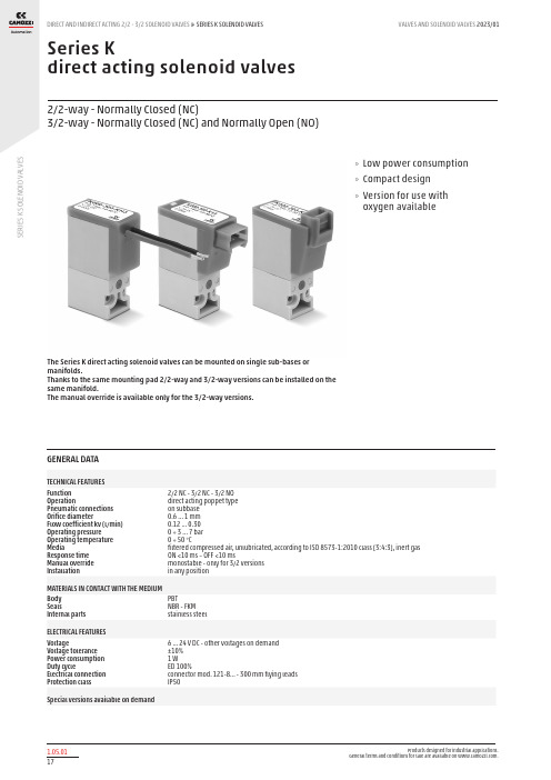
S E R I E S K S O L E N O I D V A L V E SSeries Kdirect acting solenoid valves2/2-way - Normally Closed (NC)3/2-way - Normally Closed (NC) and Normally Open (NO)The Series K direct acting solenoid valves can be mounted on single sub-bases or manifolds.Thanks to the same mounting pad 2/2-way and 3/2-way versions can be installed on the same manifold.The manual override is available only for the 3/2-way versions.»Low power consumption »Compact design »Version for use with oxygen availableGENERAL DATATECHNICAL FEATURES Function OperationPneumatic connections Orifice diameterFlow coefficient kv (l/min) Operating pressure Operating temperature MediaResponse time Manual override Installation2/2 NC - 3/2 NC - 3/2 NO direct acting poppet type on subbase 0.6 ... 1 mm 0.12 ... 0.30 0 ÷ 3 ... 7 bar 0 ÷ 50 °Cfiltered compressed air, unlubricated, according to ISO 8573-1:2010 class [3:4:3], inert gas ON <10 ms – OFF <10 msmonostable - only for 3/2 versions in any positionMATERIALS IN CONTACT WITH THE MEDIUM Body SealsInternal parts PBTNBR - FKM stainless steelELECTRICAL FEATURES VoltageVoltage tolerance Power consumption Duty cycleElectrical connection Protection class6 ... 24 V DC - other voltages on demand ±10% 1 WED 100%connector mod. 121-8... - 300 mm flying leads IP50Special versions available on demandS E R I E S K S O L E N O I D V A L V E SCODING EXAMPLES E R I E S K S O L E N O I D V A L V E Sor2x M1.6x16 screws for mounting on metal* add - VOLTAGE(see CODING EXAMPLE)Series K solenoid valve - 2/2-way NC - in-line connectorSupplied with: 1x interface seal2x Ø1.6x16 screws for mounting on plastic or2x M1.6x16 screws for mounting on metal)* add - VOLTAGE(see CODING EXAMPLE)Series K solenoid valve - 2/2-way NC - 300 mm flying leadsSupplied with: 1x interface seal2x Ø1.6x16 screws for mounting on plastic or2x M1.6x16 screws for mounting on metalS E R I E S K S O L E N O I D V A L V E Sor2x M1.6x16 screws for mounting on metal* add - VOLTAGE(see CODING EXAMPLE)Series K solenoid valve - 3/2-way NC - in-line connectorSupplied with: 1x interface seal2x Ø1.6x16 screws for mounting on plastic or2x M1.6x16 screws for mounting on metal* add - VOLTAGE(see CODING EXAMPLE)Series K solenoid valve - 3/2-way NC - 300 mm flying leadsSupplied with: 1x interface seal2x Ø1.6x16 screws for mounting on plastic or2x M1.6x16 screws for mounting on metalS E R I E S K S O L E N O I D V A L V E S2x Ø1.6x19 screws for mounting on plastic or2x M1.6x19 screws for mounting on metalFor use without port 1 and 3 inversion interface, use16 mm long screws (see accessories)* add - VOLTAGE(see CODING EXAMPLE)Series K solenoid valve - 3/2-way NO - in-line connectorSupplied with:1x interface for NO with position ports as per NC 2x interface seals2x Ø1.6x19 screws for mounting on plastic or2x M1.6x19 screws for mounting on metalFor use without port 1 and 3 inversion interface, use16 mm long screws (see accessories)* add - VOLTAGE(see CODING EXAMPLE)Series K solenoid valve - 3/2-way NO - 300 mm flying leadsSupplied with:1x interface for NO with position ports as per NC 2x interface seals2x Ø1.6x19 screws for mounting on plastic or2x M1.6x19 screws for mounting on metalFor use without port 1 and 3 inversion interface, use16 mm long screws (see accessories)S E R I E S K S O LE N O IDV A L V E SSingle sub-base for solenoid valve size 10 mmSingle sub-base suitable for Series K 2-way or 3-way solenoid valveUse solenoid valves with screws for mounting on metal (see coding)Material: anodized aluminium Connections: M5 threadsManifold Mod. K1**-02** Number of positionsWith side outlets and conveyed inlet and exhaust. Use solenoid valves with screws for mounting on metal (see coding)Material: anodized aluminiumConnections: M5 threadsPosition valve capSupplied with:1x position valve cap 3x O-Rings2x M1.6x6 screws for mounting on metalS E R I E S K S O L E N O I D V A L V ESMounting screws for Series K solenoid valves16 mm long screws for use with Series K 3/2-way NO solenoid valves without port 1 and 3 inversioninterfaceConnector with flying leads Mod. 121-8..。
挖掘机维修资料大全

0SH200-3GSH210-5SH220-3CRSH280SH330-3B 350HD3B发动机诊断服务技术信息五十铃发动机装配图片 6HK1住友中俊服务培训资料SH200-2服务手册(故障 诊断系统
)SH200-3零件手册SH200-3维护手册(电气线路篇) SH200-3维护手册(电气线路篇)SH200-3维护手册 (电气线路篇)SH200-3维护手册(概述篇)SH200-3 维护手册(维护篇)SH
200-3维护手册(液压油路篇)SH200-3维护手册(主 体篇)SH200GT-3维修手册(完全篇)SH450LHD, SH300-2维修手册中俊住友-3电气系统原理讲座视频 住友200,300EC电机的
简单测量法住友200A1A2技术服务手册(电气篇)住 友A1-A2=2电路图住友PAX性能测试过程视频住友 SH200-3液压电气技术服务手册住友SH200(220)-3电 器系统原理住友SH200A3维护
大宇12V型机操作与保养视频电路液压图7型挖掘机 培训教材()DH
220-7零件目录DH220LC-V电气系统DH225LC-7主要功 能改进介绍大宇7-MODEL液压电气培训教材大宇DH5系列-电气教材(2003)大宇V-MODEL电气培训教材 (上)大宇V-MOD
EL电气培训教材(下)大宇故障维修事例(05年版) 技术信息 ATLAS阿特拉斯—特雷克斯10 1604LC 液压系统调试1604LC_Workshop_manual1604 调试程序1804调试工作2
挖掘机电气控制系统培训教材三一挖掘机特点三一
挖掘机液压系统三一液压挖掘机培训教材(刘军士) 挖掘机培训教材-液压挖掘机结构及使用液压泵及其 控制系统液压泵进油压力对工程机械考能的影响液 压挖掘机的检查、调整
挖掘机维修资料大全.ppt
掘机维修手册ACX210-240挖掘机维修手册 BCX210,240维护手册CX330维修手册SEPAR 2000电磁 阀图示防盗机具加固凯斯24气门发动机凯斯用户培 训
现代355型机培训资料R55-3
R55-7R60-5R80-7R110LC-7R130W-3R130W-5R140LC-
7R160LC-7R180LC-7R200W-3R210LC-3R210LC7R225LC-7(中文)R250
TGPS监控STW维修服务系统卡特彼勒学习管理系统 (CLMS)客户售后服务协议(CSA)破碎锤Hammer for HEX设备工具服务光盘新产品引进(NPI)服务培 训
利勃海尔2LIEBHERR-9
42HD零件手册LIEBHERR液压系统祥解 柳工182007年柳工挖掘机总体培训资料2007年挖机 培训CLG200-3、230销售文件CLG200-3czscCLG2003ljtcCLG907零
0W服务手册ZX330-3,350LCN-3,360LC-3服务手册 ZX330-370服务手册ZX450-3,520LC-3服务手册 ZX450H 服务手册ZX600,650配件手册ZX800,850H
服务手册ZX850 870-3 服务手册代理店培训资料教育 基础培训知识日立电器动画演示汉语版日立发动机 维修手册日立建机服务快讯日立视频系列日立小大 夫软件卫星安装要领书系统图 VOLOV沃尔沃12E
义80NX電気80NX油圧回路IHI技术培训05TNV洋马维 修讲义給油脂、定期交換
KATO加藤8HD700-7--2电脑板HD800VII液压回路图 HD820-2 APC100服务手册(清晰版)H
D820-2 APC100故障代码信息HD820-2配件目录 (1)HD820-2配件目录(2)HD820-2液压图HD820服务手 册
Parker Colorflow 控制阀门(用于工业和移动应用)说明书
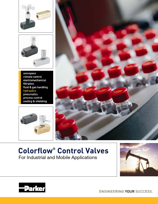
Colorflow®Control Valves For Industrial and Mobile ApplicationsFor applications requiring flow consistency with varyingpressures, Parker offers Pressure Compensated Flow Control Valves that are available in adjustable or preset flow configurations. The flowprecision is within +/-5%. There is also the option of ordering with a reverse flow check if needed.Parker Check Valves have fully guided poppets. Our superior design eliminates wobble and erratic travel that can commonly occur with less durable ball-check type construction. The soft seal poppet on the Check Valves are standard for sizes up to 1/2”NPT, #10 SAE.Metering Valves can be easily panel mounted with availablemounting kits.Parker Colorflow ®Control ValvesCustomers around the world recognize the Parker brand as the benchmark for high performance and best in industry quality.Parker’s exclusivecolor ring design on the Colorflow products provides a color-coded system of highly visiblecheckpoints for setting valveopenings accurately and quickly.The flow setting on the Flow Control, Needle , and Pressure Compensated Control Valves can be secured with thestandard set screw or with the optional thumbscrew that does not require additional tools. A further option is available that allows the flow setting to bepermanently secured.Needle ValveMetering ValveFlow Control ValveCheck ValvePressure Compensated Flow ValvesThe Parker Colorflow Valve line offers a broad range of materials, port types, and size options. Our products can be used in most markets and on numerous applications due to the product range offered. Parker’s breadth of products and engineering expertise enable us not only to supply products, but also to providesolutions.*Maximum operating pressures listed are for steel and stainless steel in most sizes.Refer to catalog for maximum operating pressure for a specific size and/or material.Offering Optimal SolutionsEngineered to world class standards, Parker Colorflow Valves are the finest, most accurate valves you can install on your machines.Series C N F MV PC*M PC*K Type Check Needle Flow MeteringAdjust Press Press Comp Comp Flow Flow Max Flow Range (LPM)11 - 56911 - 26511 - 569 4 - 11011 - 18911 - 95(GPM) 3 - 150 3 - 70 3 - 150.5 - 403 - 50 3 - 25Body MaterialBrass X X X X --Steel X X X X XXStainless Steel X X X -X -Port Type/SizesNPT ⅛" - 2"⅛" - 1¼"⅛" - 2"⅛" - 1"¼" - 1¼"¼" - ¾"SAE -4 thru -32-4 thru -20-4 thru -32-4 thru -16-6 thru -16-6 thru -12BSPP ⅛" - 2"¼" - 1"⅛" - 2"⅛" - 1"--BSPT ⅛" - ¾"-⅛" - ¾"¼" - ½"--Max Operating Press*(Bar)345345345345210210(PSI)500050005000500030003000Parker Hydraulics International Sales OfficesParker Hannifin Corporation Hydraulic Valve Division520 Ternes AvenueElyria, Ohio 44035 USATel: 440-366-5200Fax: 440-366-5253/hydraulicvalve Asia PacificAsia Pacific HeadquartersParker Hannifin Hong Kong Ltd8/F, Kin Yip Plaza9 Cheung Yee StreetHK-Cheung Sha Wan, Hong Kong Tel: 852 2428 8008Fax: 852 2425 6896Australia HeadquartersParker Hannifin Pty Ltd.9 Carrington RoadCastle Hill, NSW 2154, Australia Tel: 612 9634 7777Fax: 612 9842 5111China HeadquartersParker Hannifin Motion & Control (Shanghai) Co., Ltd280 Yunqiao Road,Jin Qiao Export Processing Zone CN-Shanghai 201206, ChinaTel: 86 21 5031 2525Fax: 86 21 5834 3714Korea HeadquartersParker Hannifin Korea Ltd6F Daehwa Plaza169 Samsung-dong, Gangnam-gu KR-Seoul, 135-090, KoreaTel: 82 2 559 0400Fax: 82 2 556 8187South AfricaParker Hannifin Africa Pty Ltd Parker Place10 Berne Avenue AeroportP.O. Box 1153ZA-Kempton Park 1620,Republic of South AfricaTel: 27 11 961 0700Fax: 27 11 392 7213Middle EastEgyptParker Hannifin Corporation8B Zahraa MaadiRegion 17FCairo, EgyptTel: (20) 2 5194018Fax: (20) 2 5190605North AmericaHydraulics Group Headquarters 6035 Parkland Boulevard Cleveland, OH 44124-4141 USA Tel: 216-896-3000Fax: 216-896-4031Parker Hannifin CanadaMotion & Control Division –Milton160 Chisholm Drive Milton Ontario Canada L9T 3G9Tel: 905-693-3000Fax: 905-876-1958MexicoParker Hannifin de MéxicoAv eje uno norte num 100Parque Industrial Toluca 2000 Toluca, Mex C.P. 50100Tel: 52 722 2754200Fax: 52 722 2799308EuropeEurope Hydraulics GroupParker Hannifin Corporation Parker House55 Maylands AvenueHemel Hempstead, HertsHP2 4SJ EnglandTel: 44 1442 458000Fax: 44 1442 458085Latin AmericaBrazilHydraulics DivisionParker Hannifin Ind. e Com. Ltda Av. FredericoRitter, 1100 Cachoeirinha RS, 94930-000 Brazil Tel: 55 51 3470 9144Fax: 55 51 3470 3100Pan American Division7400 NW 19th Street, Suite A Miami, FL 33126 USATel: 305-470-8800Fax: 305-470-8808Mobile SalesMobile Sales Organization and Global Sales595 Schelter RoadSuite 100Lincolnshire, IL 60069 USA Tel: 847-821-1500Fax: 847-821-7600 Industrial SalesGreat Lakes Region3700 Embassy Parkway Suite 260Fairlawn, OH 44333 USA Tel: 330-670-2680Fax: 330-670-2681Southern Region1225 Old Alpharetta Road Suite 290Alpharetta, GA 30005 USA Tel: 770-619-9767Fax: 770-619-9806Chicago Region1163 E. Ogden AvenueSuite 705, #358Naperville, IL 60563 USA Tel: 630-964-0796Fax: 866-473-9274Pacific Region8460 Kass DriveBuena Park, CA 90621 USA Tel: 714-228-2510Fax: 714-228-2511Eastern Region100 Corporate Drive Lebanon, NJ 08833 USA Tel: 908-236-4121Fax: 908-236-4146Gulf Region20002 Standing Cypress Drive Spring, TX 77379 USATel: 317-519-8490Fax: 866-390-4986©2008 Parker Hannifin Corporation, all rights reserved Bulletin HY14-3301/US,5M, 7/08, DCI。
微米流量控制阀说明书
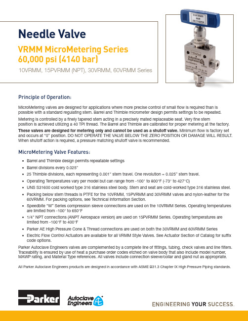
Principle of Operation:MicroMetering valves are designed for applications where more precise control of small flow is required than is possible with a standard regulating stem. Barrel and Thimble micrometer design permits settings to be repeated.Metering is controlled by a finely tapered stem acting in a precisely mated replaceable seat. Very fine stemposition is achieved utilizing a 40 TPI thread. The Barrel and Thimble are calibrated for proper metering at the factory.These valves are designed for metering only and cannot be used as a shutoff valve. Minimum flow is factory set and occurs at “0” position. DO NOT OPERATE THE VALVE BELOW THE ZERO POSITION OR DAMAGE WILL RESULT. When shutoff action is required, a pressure matching shutoff valve is recommended.MicroMetering Valve Features:• Barrel and Thimble design permits repeatable settings • Barrel divisions every 0.025"• 25 Thimble divisions, each representing 0.001" stem travel. One revolution = 0.025” stem travel.• Operating Temperatures vary per model but can range from -100° to 800°F (-73° to 427°C)• UNS S31600 cold worked type 316 stainless steel body. Stem and seat are cold-worked type 316 stainless steel.• Packing below stem threads is PTFE for the 10VRMM, 15PVRMM and 30VRMM valves and nylon-leather for the 60VRMM. For packing options, see Technical Information Section.• Speedbite “W” Series compression sleeve connections are used on the 10VRMM Series. Operating temperatures are limited from -100° to 650°F• 1/4" NPT connections (ANPT Aerospace version) are used on 15PVRMM Series. Operating temperatures are limited from -100°F to 400°F• Parker AE High Pressure Cone & Thread connections are used on both the 30VRMM and 60VRMM Series • Electric Flow Control Actuators are available for all VRMM Style Valves. See Actuator Section of Catalog for suffix code options.Parker Autoclave Engineers valves are complemented by a complete line of fittings, tubing, check valves and line filters. Traceability is ensured by use of heat a purchase order codes etched on valve body that also include model number, MAWP rating, and Material Type references. All valves include connection sleeve/collar and gland nut as appropriate.All Parker Autoclave Engineers products are designed in accordance with ASME B31.3 Chapter IX High Pressure Piping standards.Needle ValveVRMM MicroMetering Series 60,000 psi (4140 bar)10VRMM, 15PVRMM (NPT), 30VRMM, 60VRMM Series2Needle Valves: VRMM MicroMetering Series 02-0115SE 0521MicroMetering Series:Pressures to 60,000 psi (4137bar)Notes** For complete temperature ratings see pressure/temperature rating guide in Technical Information section .Valve Packing Options:Standard Parker Autoclave Engineers 10VRMM, 15PVRMM and 30VRMM Series valves with PTFE packing may be operated to 450°F (232°C). 60VRMM series valves with nylon/leather/nylon packing may be operated from 40ºF (4ºC) to 230ºF (110ºC).*TG Standard valve with PTFE glass packing -100° to 600°F (-73° to 316°).GY Standard valve with graphite braided yarn packing to 32° to 800°F (0° to 427°).B Cryogenic trim materials and PTFE packing required when below 0°F (-18°C) to -100°F (-73°C).Note: *60VRMM valves with -TG option supplied with PEEK/PTFE Glass/PEEK packingParker Autoclave Engineers does not recommend Low Pressure Speedbite sleeve connections below -100°F (-73°C) or above 650°F (343°C). NPT Pipe Connections can be used from -100° to over 400°F (-72 to 204°C) (dependent on sealant temperature range). See needle valve options for stem and seat coating for erosive service.Generalized Flow Coefficient Curves (C v )% of rated C vS t e m T r a v e l : I n c h e s (m m )0.001 0.002 0.003 0.0040.175(4.45) 0.150(3.81) 0.125(3.18) 0.100(2.54) 0.075(1.90) 0.050(1.27) 0.025(.64) 0MicroMetering (VRMM) Series Flow CurveNPT valve option will not have connection collar and gland nut as shown above.15PVRMM “NPT” version shown above3Needle Valves: VRMM MicroMetering Series 02-0115SE 0521Ordering Guide:For complete information on available stem types, optional connections and additional valve options, see Needle Valve Options section or contact your Sales Representative. VRMM Series valves are furnished complete with connection components, unless otherwise specified.Material of Construction:Basic Repair Kits for 316 SS Material:G - Packing Gland mounting hole drill size • G1 - Bracket mounting hole size • H* - Dimension is with stem in closed positionAll dimensions for reference only and subject to change • For prompt service, Parker Autoclave stocks select products. Consult factory.4Needle Valves: VRMM MicroMetering Series 02-0115SE 0521Panel Hole Sizes:*10VRMM Valve has only one mounting screw. Dimension shown is from stem center to panel hole center.10VRMM Thimble must be removed to mount on panel.Needle Valve Panel MountNotesNPT Pipe Thread Connections:NPT threads must be sealed using a high quality PTFE tape(3 wraps minimum) and/or thread sealant paste product suitablefor process temperature.Refer to thread sealant manufacturer’s instructions forapplication instructions. A good thread lubrication product(metal flake style) capable of process temperatures is also necessary to prevent thread galling.Sealing performance may vary based on many factors such as pressure, temperature, media, thread quality, thread material,proper engagement, and proper use of thread sealant.End user should limit the number of times an NPT fitting is assembled and disassembled as thread deformation during assembly will result in deteriorating seal quality over time.5Needle Valves: VRMM MicroMetering Series 02-0115SE 05216Needle Valves: VRMM MicroMetering Series 02-0115SE 0521High Temperature Extension:Required for extreme temperatures-HTHigh Temperature (over 600°F to 800°F maximum)Needle Valve Clam Shell Handle Lockout:(order separately using part numbers shown below, padlock not included)Clam Shell Handle locks are provided to lockout valves in open or closed position preventing unauthorized personnel from actuating valve during shutdown or emergency situations.This clamshell design is available in four (4) sizes dependent on handle length:P/N AE004855 – 1" to 2.5" handle length P/N 90088 – 2.5" to 5.0" handle length P/N 90194 – 6.5" to 10" handle lengthP/N AE004350 – 8" to 13" handle lengthValve Options:(For Actuator Options please reference specific Actuator brochure)Electric Valve Actuators:Parker Autoclave Engineers has developed an electric actuator capable of fine, multi-turn, control.This actuator is designed specifically for our VRMM Series valves to facilitate remote control of these high pressure low flow metering valves. 4-20mA (-C4 suffix) or 0-10VDC (-C10 suffix) control signal options areavailable.NOTES:7 Needle Valves: VRMM MicroMetering Series 02-0115SE 0521! CAUTION !Do not mix or interchange component parts or tubing with those of other manufacturers. Doing so is unsafe and will void warranty.Parker Autoclave Engineers Valves, Fittings, and Tools are not designed to interface with common commercial instrument tubing and are designed to only connect with tubing manufactured toParker Autoclave Engineers AES specifications. Failure to do so is unsafe and will void warranty.Offer of SaleThe items described in this document are available for sale by Parker Hannifin Corporation, its subsidiaries or its authorized distributors. Any sale contract entered by Parker will begoverned by the provisions stated in Parker's standard terms and conditions of sale (copy available upon request).©2021 Parker Hannifin Corporation | Autoclave Engineers is a registered trademark of the Parker Hannifin Corporation Literature #: 02-0115SE May 2021ISO-9001 CertifiedInstrumentation Products Division Autoclave Engineers Operation 8325 Hessinger Drive Erie, PA 16509-4679Tel: 814 860 5700Fax: 814 860 /ipdInstrumentation Products Division Division Headquarters 1005 A Cleaner WayHuntsville, AL 35805 USA Tel: 256 881 2040Fax: 256 881 5072Parker Hannifin Manufacturing Ltd.Instrumentation Products Division, EuropeRiverside RoadPottington Business ParkBarnstaple, UK, EX31 1NP , UK Tel: 44 1271 313131Fax: 44 1271 373636WARNINGFAILURE, IMPROPER SELECTION OR IMPROPER USE OF THE PRODUCTS AND/OR SYSTEMS DESCRIBED HEREIN OR RELATED ITEMS CAN CAUSE DEATH,PERSONAL INJURY AND PROPERTY DAMAGE.This document and other information from Parker Hannifin Corporation, its subsidiaries and authorized distributors provide product and/or system options for further investigation by users having technical expertise. It is important that you analyze all aspects of your application and review the information concerning the product or system in the current product catalog. Due to the variety of operating conditions and applications for these products or systems, the user, through its own analysis and testing, is solely responsible for making the final selection of the products and systems and assuring that all performance, safety and warning requirements of the application are met. The prod-ucts described herein, including without limitation, product features, specifications, designs, availability and pricing, are subject to change by Parker Hannifin Corporation and its subsidiaries at any time without notice.Needle Valves: VRMM MicroMetering Series 02-0115SE 0521Parker WorldwideNorth AmericaUSA – Corporate, Cleveland, OH Tel: +1 256 896 3000USA – IPD, Huntsville, AL Tel: +1 256 881 2040*****************USA – IPD, (Autoclave), Erie, PA Tel: +1 814 860 5700*******************CA – Canada, Grimsby, Ontario Tel +1 905-945-2274*********************South AmericaAR – Argentina, Buenos Aires Tel: +54 3327 44 4129 ******************BR – Brazil, Diadema, SP Diadema, SPTel: +55 11 4360 6700******************CL – Chile, Santiago Tel: +56 (0) 2 2303 9640******************MX – Mexico, Toluca Tel: +52 722 275 4200*******************Asia PacificAU – Australia, Dandenong Tel: +61 (0)2 9842 5150******************************CN – China, Shanghai Tel: +86 21 2899 5000*****************************HK – Hong Kong Tel: +852 2428 8008IN – India, MumbaiTel: +91 22 6513 7081-85ID – Indonesia, Tangerang Tel: +62 2977 7900********************JP – Japan, Tokyo Tel: +(81) 3 6365 4020******************KR – South Korea, Seoul Tel: +82 2 559 0400*******************MY – Malaysia, Selangor Tel: +603 784 90 800*******************SG – Singapore,Tel: +65 6887 6300*******************TH – Thailand, Bangkok Tel: +66 2 186 7000*********************TW – Taiwan, Taipei Tel: +886 2 2298 8987*************************VN – Vietnam, Hochi Minh City Tel: +848 382 508 56**********************Europe, Middle East, AfricaAE – UAE, Dubai Tel: +971 4 812 7100********************AT – Austria, Wiener Neustadt Tel: +43 (0)2622 23501-0*************************AT – Eastern Europe, Wiener Neustadt Tel: +43 (0)2622 23501 900****************************AZ – Azerbaijan, Baku Tel: +994 50 2233 458****************************BE/LU – Belgium, Nivelles Tel: +32 (0)67 280 900*************************BG – Bulgaria, Sofia Tel: +359 2 980 1344**************************BY – Belarus, Minsk Tel: +48 (0)22 573 24 00*************************CH – Switzerland, Etoy Tel: +41 (0) 21 821 87 00*****************************CZ – Czech Republic, Klecany Tel: +420 284 083 111*******************************DE – Germany, Kaarst Tel: +49 (0)2131 4016 0*************************DK – Denmark, Ballerup Tel: +45 43 56 04 00*************************ES – Spain, Madrid Tel: +34 902 33 00 01***********************FI – Finland, VantaaTel: +358 (0)20 753 2500*************************FR – France, Contamine s/Arve Tel: +33 (0)4 50 25 80 25************************GR – Greece, Athens Tel: +30 210 933 6450************************HU – Hungary, Budapest Tel: +36 223 885 470*************************IE – Ireland, DublinTel: +353 (0)1 466 6370*************************IT – Italy, Corsico (Ml)Tel: +39 02 45 19 21***********************KZ – Kazakhstan, Almaty Tel: +7 7273 561 000****************************NL – The Netherlands, Oldenzaal Tel: +31 (0)541 585 000********************NO – Norway, Stavanger Tel: +47 66 75 34 00************************PL – Poland, Warsaw Tel: +48 (0)22 573 24 00************************PT – Portugal, Leca da Palmeira Tel: +351 22 999 7360**************************RO – Romania, Bucharest Tel: +40 21 252 1382*************************RU – Russia, Moscow Tel: +7 495 645-2156************************SE – Sweden, Spånga Tel: +46 (0)8 59 79 50 00************************SK – Slovakia, Banská Bystrica Tel: +421 484 162 252**************************SL – Slovenia, Novo Mesto Tel: +386 7 337 6650**************************TR – Turkey, Istanbul Tel: +90 216 4997081************************UA – Ukraine, KievTel: +48 (0)22 573 24 00*************************UK – United Kingdom, Warwick Tel: +44 (0)1926 317 878********************ZA – South Africa, Kempton Park Tel: +27 (0)11 961 0700*****************************。
ZoneTight 3孔透气热水管控制阀 15说明书
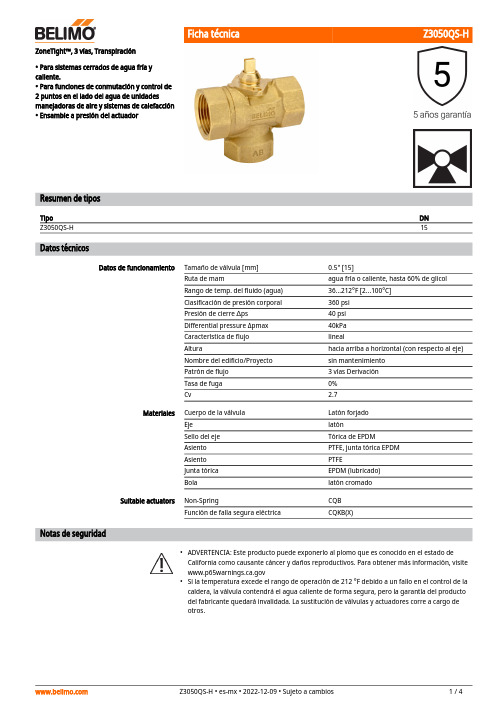
••ZoneTight™, 3 vías, Transpiración• Para sistemas cerrados de agua fría y caliente.• Para funciones de conmutación y control de 2 puntos en el lado del agua de unidades manejadoras de aire y sistemas de calefacción • Ensamble a presión del actuadorResumen de tiposTipoDN Z3050QS-H15Datos técnicosDatos de funcionamientoTamaño de válvula [mm]0.5" [15]Ruta de mamagua fría o caliente, hasta 60% de glicol Rango de temp. del fluido (agua)36...212°F [2...100°C]Clasificación de presión corporal 360 psi Presión de cierre ∆ps 40 psi Differential pressure Δpmax 40kPa Característica de flujo linealAlturahacia arriba a horizontal (con respecto al eje)Nombre del edificio/Proyecto sin mantenimiento Patrón de flujo 3 vías Derivación Tasa de fuga 0%Cv2.7MaterialesCuerpo de la válvula Latón forjado Eje latónSello del eje Tórica de EPDM Asiento PTFE, junta tórica EPDM Asiento PTFEJunta tórica EPDM (lubricado)Bolalatón cromado Suitable actuatorsNon-SpringCQB Función de falla segura eléctricaCQKB(X)Notas de seguridadADVERTENCIA: Este producto puede exponerlo al plomo que es conocido en el estado de California como causante cáncer y daños reproductivos. Para obtener más información, visite Si la temperatura excede el rango de operación de 212 °F debido a un fallo en el control de la caldera, la válvula contendrá el agua caliente de forma segura, pero la garantía del producto del fabricante quedará invalidada. La sustitución de válvulas y actuadores corre a cargo de otros.AplicaciónModo de operación Montaje directo y sencilloPosiciones de instalación recomendadasRequisitos de calidad del aguaServicioCaracterísticas del productoLas válvulas de zona QCV son adecuadas para grandes edificios comerciales donde se desea un mayor cierre y la capacidad de cambiar el flujo. Las aplicaciones comunes incluyen ventiladores unitarios, unidades fan coil, serpentines de recalentamiento VAV, carcasas de tubos de aletas, paneles radiantes y serpentines de conductos. La válvula encaja en áreas de espacio restringido y se puede ensamblar sin el uso de herramientas.Detalles de flujo / montajeLa válvula de zona para conmutación se ajusta mediante un actuador giratorio. El actuador giratorio se controla mediante una señal de apertura/cierre.Montaje a presión sin necesidad de herramientas.El actuador puede montarse en la válvula mediante presión manual (Precaución: Únicamente pueden hacerse movimientos verticales). Las pestañas deben encajar en los agujeros de la brida.La orientación de montaje con respecto a la válvula puede seleccionarse en incrementos de 180°. (Es posible hacerlo dos veces)Notas de instalaciónLa válvula de bola se puede instalar de vertical a horizontal. La válvula de bola no puedeinstalarse en posición suspendida, es decir, con el eje hacia abajo.Las válvulas Belimo son dispositivos de regulación. Para que las válvulas funcionencorrectamente a largo plazo, deben mantenerse libres de partículas (por ejemplo, cordones de soldadura durante los trabajos de instalación). Se recomienda la instalación de un filtro colador adecuado. No debe haber partículas de más de 0.04 "(1 mm).Las válvulas de bola y los actuadores giratorios no requieren mantenimiento.Antes de realizar cualquier trabajo de servicio en el elemento de control, es esencial aislar el actuador de rotación completa de la fuente de alimentación (desconectando el cableadoeléctrico si fuera necesario). También deben apagarse todas las bombas situadas en el circuito de tuberías correspondiente y deben cerrarse las válvulas de distribución adecuadas (si esnecesario, deje que todos los componentes se enfríen primero y reduzca siempre la presión del sistema hasta lograr una presión ambiental).El sistema no debe volver a ponerse en servicio hasta que la válvula de bola y el actuador giratorio se hayan reensamblado correctamente de acuerdo con las instrucciones y la tubería haya sido rellenada por personal capacitado profesionalmente.Dirección del flujo Ajuste de flujoEl sentido del flujo es posible en ambas direcciones.Debe retirarse la pinza de tope en el actuador para obtener un ángulo de giro de 90°, necesariopara la funcionalidad de cambio de régimen.Retire la pinza de tope finalDibujos dimensionalesTipo DN PesoZ3050QS-H150.44 lb [0.20 kg]CQKCQKA B C D E F4.5" [114] 2.0" [52]3,8" [97] 2.7" [69] 1.0" [25]1,0" [26]CQCQA B C D E F4.5" [114] 2.0" [52]3,7" [93] 2.6" [65] 1.0" [25]1,0" [26]。
RLM3电气快慢速选择控制阀说明书

66 260/108 EDRLM3ELECTRIC FAST / SLOW SPEEDSELECTION VALVESERIES 10MODULAR VERSION ISO 4401-03 (CETOP 03)p max 250barQ max (see table of performances)N.B. : For further informations about the flow control valve see catalogue 32 200; For further informations about the cartridge poppet valve see catalogue 43 100.NOTE:The solenoid valves are never supplied with connector. Connectors must be ordered separately. To find out the type of connector to be ordered, please see catalogue 49 000.1.1 - Coil identification codePower supply D12= 12 V D24= 24 V R110= 110 V R230= 230 V Coil electrical connection (see paragraph 10)K1= plug for connector type DIN 43650 (standard )K2= plug for connector type AMP JUNIOR K4= outgoing cablesK7= plug for connector type DEUTSCH DT04-2P male K8= plug for connector type AMP SUPER SEAL14CD -/10Series no.: (the overall and mounting dimensions remain unchanged from10 to 19)direct current (standard )rectified current@@3 - HYDRAULIC FLUIDSUse mineral oil-based hydraulic fluids HL or HM type, according to ISO 6743-4. For these fluids, use NBR seals (code N). For fluids HFDR type (phosphate esters) use FPM seals (code V). For the use of other kinds of fluid such as HFA, HFB, HFC, please consult our technical department. Using fluids at temperatures higher than 80 °C causes a faster degradation of the fluid and of the seals characteristics.The fluid must be preserved in its physical and chemical characteristics.4 - PRESSURE DROPS Δp-Q(obtained with viscosity of 36 cSt at 50 °C)5 - SWITCHING TIMEThe values are obtained according to the ISO 6403 standard, with mineral oil at 50°C, with viscosity of 36 cSt.10203051015Q [l/min]4050[bar]20p 25306 -OPERATING LIMITSThe curves define the flow rate operating fields according to the valve pressure of the different versions.The values have been obtained according to ISO 6403 norm with solenoids at rated temperature and supplied with voltage equal to 90% of the nominal voltage.The value have been obtained with mineral oil, viscosity 36 cSt,temperature 50 °C and filtration according to ISO 4406:1999 class 18/16/13.The values in graphs refer to the fast flow through the soleinoid valve and are equal for A (normally open) and C (normally closed)versions.010203050100150Q [l/min]4050[bar]200p 2508 - MANUAL OVERRIDE5 - ELECTRICAL FEATURES 5.1 SolenoidsThese are essentially made up of two parts: tube and coil. The tube is threaded onto the valve body and includes the armature that moves immersed in oil, without wear. The inner part, in contact with the oil in the return line, ensures heat dissipation. The coil is fastened to the tube by a threaded nut, and can be rotated according to the available space.The interchangeability of coils of different voltages both D or R type is possible without removing the tube.5.2 Current and absorbed powerIn the table are shown current and power consumption values relevant to the different coil types. “R” coil must be used when the valve is fed with AC power supply subsequently rectified by means of rectifier bridge, externally or incorporated in the “D” type connector (see cat. 49 000).Protection according CEI EN 60529 - atmpspheric agents NOTE:The protection degree is guaranteed only with the con-nector correctly con-nected and installed.CM for NO version (pushing type)CM for NC version (screw type)10 - ELECTRIC CONNECTIONSconnection for DIN 43650 connectorcode K1(standard )connection for AMP JUNIOR connectorcode K2connection for DEUTSCH DT04-2P male connectorcode K7connection for AMP SUPER SEAL connector (two contacts)code K8outgoing cables connectioncode K411 - ELECTRIC CONNECTORSThe solenoid valves are supplied without connectors. For coils with standard electrical connections K1 type (DIN 43650) the connectors can be ordered separately. For the identification of the connector type to be ordered please see catalog 49 000.For K2, K7 and K8 connection type the relative connectors are not available.DUPLOMATIC OLEODINAMICA SpA20025 LEGNANO (MI) - P.le Bozzi, 1 / Via Edison Tel. 0331/472111 - Fax 0331/548328。
KMX15R使用说明书

控制阀KMX15R说明书川崎重工有限公司精密机械分部目录页码Ⅰ.规格 3 1.外观 3 2.技术数据 3Ⅱ.结构和动作 4 1.结构 4 2.动作 12Ⅲ.拆卸和安装 24 1.一般注意事项 24 2.工具 24 3.拆卸 24 4.安装 27Ⅳ.维修标准 30 1.零件检验 30Ⅴ.故障清除 31 1.控制阀 31 2.卸压阀 32Ⅰ.规格1. 外观2.技术数据项目规格型号KMX15R/B45051 最大流量(L/min)110(每台泵)最大压力(MPa)34.3液压油温度范围(℃)-20~90主卸压阀设定压力(MPa)80L/min 时:31.4(标准)60L/min 时:34.3 (较高)端口卸压阀设定压力(MPa)20L/min 时:34.3 负向控制卸压阀设定压力(MPa)30L/min 时:3.2(2) 主卸压阀表2编号零件名称数量备注编号零件名称数量备注103 旋入套 1 力矩69~78N.m 562 挡圈 1104 调节套 1 611 提动头 1121 C形圈 1 613 挡块 1122 垫圈 1 614 活塞 1123 C形圈 1 621 弹簧 1124 过滤件挡块 1 652 调节螺钉 1125 过滤件 1 661 O形圈 1 P8163 O形圈 1 P25 663 O形圈 1 P14512 柱塞 1 664 O形圈 1 P16521 弹簧 1 671 锁紧螺母 1 力矩27~31 N.m 541 基座 1 673 锁紧螺母 1 力矩27~31 N.m 561 O形圈 1 P16V(3)端口卸压阀表3编号零件名称数量备注编号零件名称数量备注101 阀体 1 力矩69~78N.m 541 基座 1102 旋入套 1 力矩69~78N.m 561 O形圈 1 P16V161 O形圈 1 P24 562 挡圈 1162 O形圈 1 P22.4 563 O形圈 1 P16V123 C形圈 1 564 挡圈 1124 过滤件挡块 1 611 提动头 1125 过滤件 1 612 弹簧基座 1301 活塞 1 621 弹簧 1511 柱塞 1 651 调节螺钉 1521 弹簧 1 661 O形圈 1 P8522 弹簧 1 671 锁紧螺母 1 力矩27~31 N.m (4)、直行阀集成块表4编号零件名称数量备注编号零件名称数量备注103 直行阀集成块 1 324 弹簧 1154 RO 塞子 1 力矩69~78N.m 325 弹簧 1156 RO 塞子 2 力矩34~39N.m 338 挡块 1159 塞子8 力矩5.9~8.8N.m 357 小孔 2 力矩15~18N.m 163 O形圈 2 P11 391 直行阀柱 1164 O形圈 1 P14 511 提动头 2165 O形圈 4 G30 521 弹簧 2166 O形圈 2 P10 551 塞子 3 力矩147~176N.m 167 O形圈 3 P12 561 O形圈 3 P24251 旋入套 1 力矩69~78N.m 601 主卸压阀 1 力矩69~78N.m 266 O形圈 4 G25 974 内六角螺钉 5 M18×1.5-95308 安装序列 1 力矩69~78N.m(4) ①安装序列图7表5编号零件名称数量备注376 弹簧基座 1375 弹簧 1356 旋入套 1 力矩69~78N•m347 挡块 1346 套 1344 套 1309 活塞 1308 阀柱 1267 O形圈 1 P10A266 O形圈 1 P24(5) 安装支臂阀柱表6编号零件名称数量备注编号零件名称数量备注302 阀柱 1 341 塞子 1 力矩59~69N.m 312 次级级柱 1 342 套(1) 1313 活塞 1 343 垫衬螺栓 1 力矩9.8~11.8N.m 314 套(2) 1 349 挡块(1) 1328 弹簧A1 1 352 塞子 1 力矩59~69N.m 329 弹簧A2 1 358 弹簧基座 1338 弹簧 1 359 弹簧基座 1339 C形圈 1(6) 安装主臂阀柱表7编号零件名称数量备注编号零件名称数量备注303 阀柱1353 塞子1力矩59~69N.m (7) 安装负向控制卸压阀表8编号零件名称数量备注编号零件名称数量备注611 提动头 1 632 套 1621 弹簧 1 638 过滤件 1631 卸压柱 1(8) 安装直行阀柱表9编号零件名称数量备注编号零件名称数量备注391 阀柱 1 340 弹簧 1317 柱塞3 1 352 塞子 1 力矩49~59N.m (9) 安装锁定阀表10编号零件名称数量备注编号零件名称数量备注101 外壳 1 201 旋入套 1 力矩74N•m 161 O形圈 1 P22A 301 塞子 1 力矩34~39N•m 162 O形圈 3 P16 511 阀柱 1163 O形圈 2 P7 512 弹簧 1164 O形圈 1 P11 541 衬套 1171 内六角头螺钉 4 M6-50(10) 液压回路图132.动作(1)各阀柱在中间位置[导向回路]伺服压力油从PG口进入,通过小孔(357),然后从侧面旁路(4)流向卸油口(Dr1)。
阀门定位器说明书3300

1 用户须知
1.1 安全指示
定位器先上电,后供气源; 产品使用过程中,不要随意的触摸反馈连接装置; 产品必须正确安装、正确操作和正确维护。
1.2 开箱清单
MVP 智能阀门定位器; 安装配件; 用户手册; 另外订制附件,详见装箱清单。
1.3 重要信息提示
为了您能更好地应用这份说明,以及保障你在调试,运行和维修这台仪器时的安全,请注意下列符
3 技术参数 ...................................................................................................................................................... 3
5 调节操作 ...................................................................................................................................................... 9
MVP 智能电气阀门定位器 3300 系列
用户手册
1 用户须知 ...................................................................................................................................................... 1
6 参数解释 .................................................................................................................................................... 17
负流量控制国产中型挖掘机主阀总成(川崎KMX15RA)结构原理分析

负流量控制国产中型挖掘机主阀总成结构与原理分析导读:本篇章主要分析负流量控制的国产中型挖掘机的主阀总成(川崎KMX15RA)的结构、工作原理、增力、自动怠速、保持、再生、优先、合分流等功能。
附有大量结构原理图、零部件图、局部液压回路分析图等。
1、主阀总成概述对于该型主阀总成,主要由控制各执行元件的主换向阀芯、主溢流阀、油缸类执行元件的过载补油阀、主油路单向阀及其它用于多种局部控制的相关阀件及阀体组成。
该机型使用的主阀总成基本参数如表1所示。
表1 主阀总成基本参数型号川崎KMX15RA标准流量(L/min)250溢流压力(MPa)31.4/34.3过载阀设定压力(MPa)36负流量溢流节流阀设定压力3.2(MPa)液压油温度范围(℃)-20~90对于该主阀总成,其六面视图及各管口标注如图1所示。
图1 主阀总成六面视图对于图1,其上各标注字母的管口名称解释如表2所示。
表2 主阀总成各管口名称符号接口名称符号接口名称R1回转补油接口Pz 主溢流阀升压用先导接口Ck1铲斗合流接口Py 行走压力开关信号接口Ck2铲斗合流接口Px (除行走以外)工作装置压力开关信号接口XAtr右行走前进先导接口PG 先导压力源接口XBtr 右行走后退先导接口PH先导压力源接口(XAo)(选装件先导接口)Pns回转逻辑阀先导接口(XBo)(选装件先导接口)PBP动臂优先阀先导接口XAk 铲斗挖掘先导接口Dr1泄漏油接口XBk 铲斗卸载先导接口Dr2泄漏油接口XAb1动臂提升先导接口Dr3泄漏油接口XBb1动臂下降先导接口Dr4泄漏油接口XAa2斗杆收回合流先导接Dr6泄漏油接口口XBa2斗杆伸出合流先导接口PaL斗杆保持阀(锁止阀)先导接口XAtL 左行走前进先导接口PbL动臂保持阀(锁止阀)先导接口XBtL 左行走后退先导接口Atr右行走马达(前进)主油接口XAs 左回转先导接口Btr右行走马达(后退)主油接口XBs 右回转先导接口(Ao)(选装件主油接口)XAa1斗杆收回先导接口(Bo)(选装件主油接口)XBa1斗杆伸出先导接口Ak1铲斗油缸无杆腔主油接口XAb2动臂提升合流先导接口Bk1铲斗油缸有杆腔主油接口(Psp)(回转优先先导接口)Ab1动臂油缸无杆腔主油接口XAas 斗杆收回时限制行程的先导接口Bb1动臂油缸有杆腔主油接口XAks 铲斗挖掘时限制行程的先导接口AtL左行走马达(前进)主油接口XBp1铲斗合流先导接口BtL右行走马达(后退)主油接口Dr5泄漏油接口As回转马达(左回转)主油接口P1泵接口(P1侧)Bs回转马达(右回转)主油接口P2泵接口(P2侧)Aa1斗杆油缸无杆腔主油接口R2主回油接口Ba1斗杆油缸有杆腔主油接口主阀总成的液压回路图如图2所示。
(完整版)03KMX15R控制阀说明书
控制阀KMX15R 说明书二00三年三月编Ⅰ.规格31.外观32.技术数据3Ⅱ.结构和动作41.结构42.动作13Ⅲ.拆卸和安装341.一般注意事项342.工具353.拆卸354.安装48Ⅳ.维修标准561.零件检验56Ⅴ.故障清除571.控制阀582.安全阀60Ⅰ.规格1. 外观2.技术数据表1项目规格型号KMX15R/B45051最大流量(L/min)110(每台泵)最大压力(Mpa)34.3液压油温度范围(℃)-20~90主安全阀设定压力(Mpa) 80L/min 时:31.4(标)60L/min 时:34.3 (较高)过载阀设定压力(Mpa)20L/min 时:34.3负向控制卸压阀30L/min 时:3.2设定压力(Mpa)表 2(3)过载阀编号 零件名称 数量 备注编号 零件名称 数量 备注103 旋入套 1 力矩69~78N •m 562 挡圈 1 104 调节套 1 611 导阀阀芯 1 121 C 形圈 1 613 挡块 1 122 垫圈 1 614 活塞 1 123 C 形圈1 621 弹簧 1 124 过滤件挡块 1 652 调节螺钉 1 125 过滤件 1 661 O 形圈 1 P8 163 O 形圈 1 P25 663 O 形圈 1 P14 512 阀芯 1 664 O 形圈 1 P16521 弹簧 1 671 锁紧螺母 1 力矩27~31 N •m 541 基座 1673 锁紧螺母 1 力矩27~31 N •m 561O 形圈1P16V表 3(3) 直行阀集成块编号零件名称数量备注编号零件名称数量 备注101 阀体 1 力矩69~78N •m 541 基座 1102 旋入套 1 力矩69~78N •m 561 O 形圈 1 P16V 161 O 形圈 1 P24 562 挡圈 1162 O 形圈 1 P22.4 563 O 形圈 1 P16V 123 C 形圈1 564 挡圈 1 124 过滤件挡块 1 611 导阀阀芯 1 125 过滤件 1 612 弹簧座 1 301 活塞 1 621 弹簧 1 511 主阀芯 1 651 调节螺钉 1 521 弹簧 1 661 O 形圈 1 P8522 弹簧1671 锁紧螺母1 力矩27~31 N •m表4编号零件名称数量备注编号零件名称数量备注103 直行阀集成块 1 324 弹簧 1154 RO 堵头 1 力矩69~78N•m 325 弹簧 1156 RO 堵头 2 力矩34~39N•m 338 挡块 1159 堵头8 力矩5.9~8.8N•m 357 节流塞 2 力矩15~18N•m 163 O形圈 2 P11 391 直行阀杆 1164 O形圈 1 P14 511 单向阀芯 2165 O形圈 4 G30 521 弹簧 2166 O形圈 2 P10 551 堵头 3 力矩147~176N•m 167 O形圈 3 P12 561 O形圈 3 P24251 旋入套 1 力矩69~78N•m 601 主安全阀 1 力矩69~78N•m 266 O形圈 4 G25 974 内六角螺钉 5 M18×1.5-95308 导阀总成 1 力矩69~78N•m(4)导阀总成图7表5编号零件名称数量备注376 弹簧座 1375 弹簧 1356 旋入套 1 力矩69~78N•m347 挡块 1346 套 1344 套 1309 导杆 1308 阀芯 1表6编号零件名称数量备注编号零件名称数量备注302 阀杆 1 341 堵头 1 力矩59~69N•m 312 次级阀芯 1 342 套(1) 1313 顶杆 1 343 螺栓 1 力矩9.8~11.8N•m 314 套(2) 1 349 挡块(1) 1328 弹簧A1 1 352 堵头 1 力矩59~69N•m 329 弹簧A2 1 358 弹簧座 1338 弹簧 1 359 弹簧座 1339 C形圈 1表7编号零件名称数量备注编号零件名称数量备注303 阀杆1353 堵头1力矩59~69N•m表8编号零件名称数量备注编号零件名称数量备注611 阀芯 1 632 套 1 621 弹簧 1 638 过滤件 1 631 弹簧座 1表9编号零件名称数量备注编号零件名称数量备注391 阀杆 1 340 弹簧 1317 内阀芯3 1 352 堵头 1 力矩49~59N•m(9)表10编号零件名称数量备注编号零件名称数量备注101 阀体 1 201 旋入套 1 力矩74N•m 161 O形圈 1 P22A 301 堵头 1 力矩34~39N•m 162 O形圈 3 P16 511 阀芯 1163 O形圈 2 P7 512 弹簧 1164 O形圈 1 P11 541 阀套 1(10) 液压回路图132.功能(1)中位时[先导回路]伺服压力油经入口PG 、小孔357,从旁路通道(4)流向排油孔(Dr1)。
卡莫奇 型号 GSCU,GMCU,GSCO,GMCO 阀门 流量控制阀 手册说明书
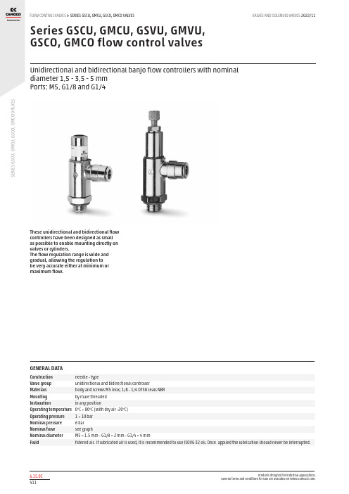
S E R I E S G S C U , G M C U , G S C O , G M C O V A L V E SSeries GSCU, GMCU, GSVU, GMVU, GSCO, GMCO flow control valvesUnidirectional and bidirectional banjo flow controllers with nominal diameter 1,5 - 3,5 - 5 mm Ports: M5, G1/8 and G1/4These unidirectional and bidirectional flow controllers have been designed as small as possible to enable mounting directly on valves or cylinders.The flow regulation range is wide and gradual, allowing the regulation to be very accurate either at minimum or maximum flow.GENERAL DATAConstruction needle - typeValve group unidirectional and bidirectional controller Materials body and screws M5 inox; 1/8 - 1/4 OT58 seals NBR Mounting by male threaded Installation in any position Operating temperature 0°C ÷ 80°C (with dry air -20°C)Operating pressure 1 ÷ 10 bar Nominal pressure 6 bar Nominal flow see graphNominal diameter M5 = 1.5 mm - G1/8 = 2 mm - G1/4 = 4 mmFluidfiltered air. If lubricated air is used, it is recommended to use ISOVG 32 oil. Once applied the lubrication should never be interrupted.S E R I E S G S C U , G M C U , G S C O , G M C OV A L V E SCODING EXAMPLETo ensure the right choice of unidirectional flow controller, proceed as follows: calculate the quantity of air in Nl/min (see cylinder Table); determine the stroke time of the cylinder; refer to graph to see which controller is the right type.S E R I E S G S C U , G M C U , G S C O , G M C O V A L V E STo ensure the right choice of unidirectional flow controller, proceed as follows: calculate the quantity of air in Nl/min (see cylinder Table); determine the stroke time of the cylinder; refer to graph to see which controller is the right type.In the case of bidirectional regulators, refer to the graph and check whether the flow control range is suitable for the work required.M5Flow Qn (Nl/min.) from 2 → 1 with controller OPEN: 70 Flow Qn (Nl/min.) from 2 → 1 with controller CLOSED: 33N° = number of screw turnsNB: Qn is determined with a supply pressure of 6 bar and with ΔP = 1 bar at the outlet.UNIDIRECTIONAL AND BIDIRECTIONAL FLOW CONTROL REGULATORSG1/8Flow Qn (Nl/min.) from 2 → 1 with controller OPEN: 440 Flow Qn (Nl/min.) from 2 → 1 with controller CLOSED: 170N° = number of screw turnsNB: Qn is determined with a supply pressure of 6 bar and with ΔP = 1 bar at the outlet.G1/4Flow Qn (Nl/min.) from 2 → 1 with controller OPEN: 790 Flow Qn (Nl/min.) from 2 → 1 with controller CLOSED: 460N° = number of screw turnsNB: Qn is determined with a supply pressure of 6 bar and with ΔP = 1 bar at the outlet.UNIDIRECTIONAL AND BIDIRECTIONAL FLOW CONTROL REGULATORSS E R I E S G S C U , G M C U , G S C O , G M C O V A L V E SUnidirectional flow controller for mounting on single-acting or double-acting cylinders. Screwdriver adjustment.Ports: M5, G1/8, G1/4 .Valves Series GMCUUnidirectional flow controller for mounting on single-acting or double-acting cylinders. Knurled screw adjustment.Ports: M5, G1/8, G1/4.Valves Series GSVUUnidirectional flow controller for mounting on valves.Screwdriver adjustment.Ports: M5, G1/8, G1/4.S E R I E S G S C U , G M C U , G S C O , G M C O V A L V ESUnidirectional flow controller for mounting on valve. Adjustment of setting by a manually operated knurled screw.Ports: M5, G1/8, G1/4.Valves Series GSCOBidirectional flow controller. Screwdriver adjustment.Ports: M5, G1/8, G1/4.Valves Series GMCOBidirectional flow controller.Adjustment of setting by a manually operated knurled screw.Ports: M5, G1/8, G1/4.。
三位元阀门说明书

basicnumber
230V / 50Hz 230V / 50Hz
24V / DC 24V / DC 230V / 50Hz
voltage suffix
suffix
80017GB-2016/R01
All leaflets are available on: www.asconumatics.eu 2-20-2
- SC
basic catalogue
number
brass stainlessst.
0
16
16 10,5 11,2 l
l
l
-
l 370A016 370A046
0
10
10 10,5 11,2 l
l
l
-
l 370A017 370A047
0
5
5
10,5 11,2 l
l
l
-
l 370A018 370A048
SERIES 370
PREFIX TABLE
prefix 1234567
description
powerlevel LP RP IP66/67 - Metal enclosure (EN/IEC 60079-7,-18 and -31)* - - - l(1)
GENERAL
Differential pressure Maximum viscosity Response time
See"SPECIFICATIONS"[1bar=100kPa] 40cSt(mm2/s)
5-20ms
fluids ()
卡莫齐3系列阀门和电磁阀产品说明书
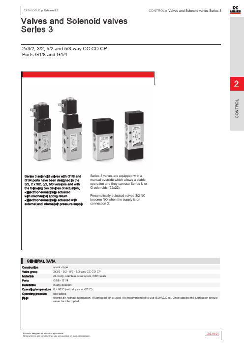
Valves and Solenoid valves Series 32x3/2, 3/2, 5/2 and 5/3-way CC CO CPPorts G1/8 and G1/4Series 3 solenoid valves with G1/8 and G1/4 ports have been designed in the 3/2, 2 x 3/2, 5/2, 5/3 versions and with the following two devices of actuation: - Electropneumatically actuatedwith mechanical spring return- Electropneumatically actuated with external and internal air pressure supply Series 3 valves are equipped with a manual override which allows a stable operation and they can use Series U or G solenoids (22x22). Pneumatically actuated valves 3/2 NC become NO when the supply is on connection 3.GENERAL DATAConstruction spool - typeValve group2x3/2 - 3/2 - 5/2 - 5/3-way CC CO CPMaterials AL body, stainless steel spool, NBR sealsPorts G1/8 - G1/4Installation in any positionOperating temperature0 ÷ 60°C (with dry air at -20°C)Operating pressure see tablesFluid filtered air, without lubrication. If lubricated air is used, it is recommended to use ISOVG32 oil. Once applied the lubrication should never be interrupted.Products designed for industrial applications.General terms and conditions for sale are available on ./2.10.022Example of solenoid valve with a bistable standard manual override.Example of solenoid monostable valve (IM) and bistable valve with a lever type manual override (IL). Both versions are available on demand. To order them it is necessary to add IM or IL at the end of the code. Code ex.: 454-015-22-U77IL.NewProducts designed for industrial applications.General terms and conditions for sale are available on ./2.10.03 2Mounting Function Flow rate (Nl/min)Operating pressure (bar)Symbol 338-015-02in-line3/2 NC7002,5 ÷ 10EV10 338L-015-02on manifold3/2 NC7002,5 ÷ 10EV10 348-015-02in-line3/2 NO7002,5 ÷ 10EV12 348L-015-02on manifold3/2 NO7002,5 ÷ 10EV123/2-way solenoid valve, G1/8, bistable - Mod. 338...These solenoid valves, which haveelectropneumatic actuation andreturn, assume the NC (closed) orNO (open) position depending onthe last pulse received.Mounting Flow rate (Nl/min)Operating pressure (bar)in-line7001,5 ÷ 10 on manifold7001,5 ÷ 10Function Flow rate (Nl/min)Operating pressure (bar)Pilot pressure (bar)Symbol2 x 3/2 NC7002,5 ÷ 10-EV392 x 3/2 NO7002,5 ÷ 10-EV412 x 3/2 NC700-0,9 ÷ 102,5 ÷ 10EV402 x 3/2 NO700-0,9 ÷ 102,5 ÷ 10EV441 x 3/2 NC + 1 x 3/2 NO7002,5 ÷ 10-EV431 x 3/2 NC + 1 x 3/2 NO700-0,9 ÷ 102,5 ÷ 10EV425/2-way solenoid valve, G1/8, monostable - Mod. 358...These solenoid valves, which have electropneumatic actuation and spring return, are suitable for operatingdouble-acting cylinders.Function Flow rate (Nl/min)Operating pressure (bar)Pilot pressure (bar)Symbol7002,5 ÷ 10-EV18700-0,9 ÷ 102,5 ÷ 10EV197002,5 ÷ 10-EV21Products designed for industrial applications.General terms and conditions for sale are available on .Products designed for industrial applications.General terms and conditions for sale are available on ./2.10.05 2Function Flow rate (Nl/min)Operating pressure (bar)Pilot pressure (bar)Symbol 7001,5 ÷ 10-EV23700-0,9 ÷ 101,5 ÷ 10EV255/3-way solenoid valve, G1/8, - Mod. 368... Mod. 378... Mod. 388...CC = Centres Closed CO = Centres Open CP = Pressure CentresFunction Flow rate (Nl/min)Operating pressure (bar)Pilot pressure (bar)Symbol 5/3 CC700 2 ÷ 10-EV28 5/3 CC700-0,9 ÷ 10 2 ÷ 10EV29 5/3 CO7002-10-EV32 5/3 CO700-0,9 ÷ 10 2 ÷ 10EV34 5/3 CP700 2 ÷ 10-EV36 5/3 CP700-0,9 ÷ 10 2 ÷ 10EV37Mounting Function Flow rate (Nl/min)Operating pressure (bar)Pilot pressure (bar)Symbol 3/2 NC1300 2.5 ÷ 10-EV103/2 NC1300-0.9 ÷ 10 2.5 ÷ 10EV113/2 NO1300 2.5 ÷ 10-EV123/2 NO1300-0.9 ÷10 2.5 ÷ 10EV133/2-way solenoid valve, G1/4, bistable - Mod. 334...These solenoid valves, which have electropneumatic actuation and return assume the NC (closed) or NO(open) position depending on ther last pulse received.Mounting Function Flow rate (Nl/min)Operating pressure (bar)Pilot pressure (bar)Symbol 3/21300 1.5 ÷ 10-EV143/21300-0.9 ÷ 10 2.5 ÷ 10EV15Products designed for industrial applications.General terms and conditions for sale are available on .Products designed for industrial applications.General terms and conditions for sale are available on ./2.10.07 2Function Flow rate (Nl/min)Operating pressure (bar)Pilot pressure (bar)Symbol2 x 3/2 NC12002,5 ÷ 10-EV392 x 3/2 NO10502,5 ÷ 10-EV412 x 3/2 NC1200-0,9 ÷ 102,5 ÷ 10EV402 x 3/2 NO1050-0,9 ÷ 102,5 ÷ 10EV44 1 x 3/2 NC + 1 x 3/2 NO1050 2 ÷ 10-EV43 1 x 3/2 NC + 1 x 3/2 NO1050-0,9 ÷ 102,5 ÷ 10EV425/2-way solenoid valve, G1/4, monostable - Mod. 354...These solenoid valves, which have electropneumatic actuation and spring return, are suitable for operating double-acting cylinders.Function Flow rate (Nl/min)Operating pressure (bar)Pilot pressure (bar)Symbol 13002,5 ÷ 10-EV181300-0,9 ÷ 102,5 ÷ 10EV19Function Flow rate (Nl/min)Operating pressure (bar)Pilot pressure (bar)Symbol13001,5 ÷ 10-EV231300-0,9 ÷ 102,5 ÷ 10EV255/3-way solenoid valve, G1/4, - Mod. 364... Mod. 374... Mod. 384...CC = Centres Closed CO = Centres Open CP = Pressure CentresFunction Flow rate (Nl/min)Operating pressure (bar)Pilot pressure (bar)Symbol5/3 CC12002,5 ÷ 10-EV285/3 CC1200-0,9 ÷ 102,5 ÷ 10EV295/3 CO12002,5 ÷ 10-EV325/3 CO1200-0,9 ÷ 102,5 ÷ 10EV345/3 CP12002,5 ÷ 10-EV365/3 CP1200-0,9 ÷ 102,5 ÷ 10EV37Products designed for industrial applications.General terms and conditions for sale are available on .Products designed for industrial applications.General terms and conditions for sale are available on ./2.10.09 2Function Flow rate (Nl/min)Min. pilot pressure (bar)Working pressure (bar)A A1B C D E F G H I L M N O P S T3/2 NC700-0.9 ÷ 10G1/8G1/85 3.2- 5.71821.41821.469.822-11.53230.4-3/2 NC700-0.9 ÷ 10G1/8G1/8- 3.231.45.71821.4-21.469.82217.411.53230.4-3/2 NC1300-0.9 ÷ 10G1/4- 4.1---2221.42221.47325-164032.4M5 3/2-way valve, G1/8 or G1/4, bistableFunction Flow rate (Nl/min)Min. pilot pressure (bar)Working pressure (bar)A A1B C D E F G H I L M N O P S 3/2700-0.9 ÷ 10G1/8G1/85---1830.41830.478.822-11.53241.7on manifold3/2700-0.9 ÷ 10G1/8G1/85 3.213.432.71830.4-30.478.82217.4-3241.7 3/21300-0.9 ÷ 10G1/4- 4.1---2229.72229.781.325-164040.7M5min pilot pressure (bar)Working pressure (bar)A A1B C D E F G H I L M N0P S 2,5-0,9 ÷ 10G1/8G1/853,231,423,83621,41830,487,82217,411,53230,43-0,9 ÷ 10G1/4-4,13,23625,44421,42230,4952521164032,45/2-way valve, G1/8 or G1/4, bistableIn-line or manifold mountingmin. pilot pressure (bar)Working pressure (bar)A A1B C D E F G H I L M N O P S 1,5-0,9 ÷ 10G1/8G1/853,231,432,83630,41839,496,82217,411,53239,42,5-0,9 ÷ 10G1/44,13,23633,74429,72240,7103,32521164040,7Products designed for industrial applications.General terms and conditions for sale are available on .Flow rate (Nl/min)Min. pilot press. (bar)Working pressure (bar)A A1B C D E F G H I L M N O P S T 7002,5-0,9 ÷ 10G1/8G1/853,231,432,83630,41839,496,82217,411,53239,4-12002,5-0,9 ÷ 10G1/4-4,13,23633,74429,72240,7103,32521164040,7M57002,5-0,9 ÷ 10G1/8G1/853,231,432,83630,41839,496,82217,411,53239,4-10502,5-0,9 ÷ 10G1/4-4,13,23633,74429,72240,7103,32521164040,7M57002,5-0,9 ÷ 10G1/8G1/853,231,432,83630,41839,496,82217,411,53239,4-10502,5-0,9 ÷ 10G1/4-4,13,23633,74429,72240,7103,32521164040,7M52 x 3/2-way valve, G1/8 or G1/4In-line or manifold mountingFunction Flow rate (Nl/min)min. pilot press. (bar)Working pressure (bar)A A1B C D E F G H I L M N O P S T 2x3/2 NC7002,5-0,9 ÷ 10G1/8G1/853,231,432,83630,41839,496,82217,411,53239,4-2x3/2 NC10502,5-0,9 ÷ 10G1/4-4,13,23633,74429,72240,7103,32521164040,7M5 2x3/2 NO7002,5-0,9 ÷ 10G1/8G1/853,231,432,83630,41839,496,82217,411,53239,4-2x3/2 NO10502,5-0,9 ÷ 10G1/4-4,13,23633,74429,72240,7103,32521164040,7M5 2x3/2 NC/NO7002,5-0,9 ÷ 10G1/8G1/853,231,432,83630,41839,496,82217,411,53239,4-2x3/2 NC/NO10502,5-0,9 ÷ 10G1/4-4,13,23633,74429,72240,7103,32521164040,7M5out of productionThe fixing screws of the valvesmod. 1635-01 and the washersmod. 2661 must be orderedseparately.Manifold bars with separate exhausts (high version)out of productionThe fixing screws of the valvesmod. 1635-01 and the washersmod. 2661 must be orderedseparately.CNVL-3H3: for Series 3, G1/8CNVL-4H3: for Series 3, G1/4 Initial / final Module with 2 positions - Mod. CNVL-...CNVL-3H2: for Series 3, G1/8CNVL-4H2: for Series 3, G1/4 Intermediate module with 3 positions - Mod. CNVL-...CNVL-3I3: for Series 3, G1/8CNVL-4I3: for Series 3, G1/4DIMENSIONS Mod.B CNVL-3I223 CNVL-4I226CNVL-3I2: for Series 3, G1/8CNVL-4I2: for Series 3, G1/4 Intermediate module with 1 position - Mod. CNVL-...DIMENSIONS Mod.DCNVL-3I146 CNVL-4I160CNVL-3I1: for Series 3, G1/8 CNVL-4I1: for Series 3, G1/4DIMENSIONSMod.C DCNVL-3H69,546 CNVL-4H8860CNVL-3H: for Series 3, G1/8CNVL-4H: for Series 3, G1/4 Interface module manifold between Series 3 G1/8 and G1/4Mod.CNVL-4H-3H It is possible to seat 1 valve, series 3 with G1/8 port.DIMENSIONS Mod.G CNVL-3P G1/4CNVL-4PG1/4CNVL-3P: for Series 3, G1/8 CNVL-4P: for Series 3, G1/4DIMENSIONS VL-3H-TP CNVL-4H-TPCNVL-3H-TP: for Series 3, G1/8 CNVL-4H-TP: for Series 3, G1/4Mod.TCNVL/3TCNVL/3: for Series 3 G1/8Blanking plate for CNVL manifolds, Mod. CNVL...DIMENSIONS Mod.A B CNVL/1517.4CNVL/4521CNVL/1: for Series 3 G1/8 CNVL/4: for Series 3 G1/4。
- 1、下载文档前请自行甄别文档内容的完整性,平台不提供额外的编辑、内容补充、找答案等附加服务。
- 2、"仅部分预览"的文档,不可在线预览部分如存在完整性等问题,可反馈申请退款(可完整预览的文档不适用该条件!)。
- 3、如文档侵犯您的权益,请联系客服反馈,我们会尽快为您处理(人工客服工作时间:9:00-18:30)。
控制阀KMX15R 说明书二00三年三月编Ⅰ.规格31.外观32.技术数据3Ⅱ.结构和动作41.结构42.动作13Ⅲ.拆卸和安装341.一般注意事项342.工具353.拆卸354.安装48Ⅳ.维修标准561.零件检验56Ⅴ.故障清除571.控制阀582.安全阀60Ⅰ.规格1. 外观2.技术数据表1项目规格型号KMX15R/B45051最大流量(L/min)110(每台泵)最大压力(Mpa)34.3液压油温度范围(℃)-20~90主安全阀设定压力(Mpa) 80L/min 时:31.4(标)60L/min 时:34.3 (较高)过载阀设定压力(Mpa)20L/min 时:34.3负向控制卸压阀30L/min 时:3.2设定压力(Mpa)表 2(3)过载阀编号 零件名称 数量 备注编号 零件名称 数量 备注103 旋入套 1 力矩69~78N •m 562 挡圈 1 104 调节套 1 611 导阀阀芯 1 121 C 形圈 1 613 挡块 1 122 垫圈 1 614 活塞 1 123 C 形圈1 621 弹簧 1 124 过滤件挡块 1 652 调节螺钉 1 125 过滤件 1 661 O 形圈 1 P8 163 O 形圈 1 P25 663 O 形圈 1 P14 512 阀芯 1 664 O 形圈 1 P16521 弹簧 1 671 锁紧螺母 1 力矩27~31 N •m 541 基座 1673 锁紧螺母 1 力矩27~31 N •m 561O 形圈1P16V表 3(3) 直行阀集成块编号零件名称数量备注编号零件名称数量 备注101 阀体 1 力矩69~78N •m 541 基座 1102 旋入套 1 力矩69~78N •m 561 O 形圈 1 P16V 161 O 形圈 1 P24 562 挡圈 1162 O 形圈 1 P22.4 563 O 形圈 1 P16V 123 C 形圈1 564 挡圈 1 124 过滤件挡块 1 611 导阀阀芯 1 125 过滤件 1 612 弹簧座 1 301 活塞 1 621 弹簧 1 511 主阀芯 1 651 调节螺钉 1 521 弹簧 1 661 O 形圈 1 P8522 弹簧1671 锁紧螺母1 力矩27~31 N •m表4编号零件名称数量备注编号零件名称数量备注103 直行阀集成块 1 324 弹簧 1154 RO 堵头 1 力矩69~78N•m 325 弹簧 1156 RO 堵头 2 力矩34~39N•m 338 挡块 1159 堵头8 力矩5.9~8.8N•m 357 节流塞 2 力矩15~18N•m 163 O形圈 2 P11 391 直行阀杆 1164 O形圈 1 P14 511 单向阀芯 2165 O形圈 4 G30 521 弹簧 2166 O形圈 2 P10 551 堵头 3 力矩147~176N•m 167 O形圈 3 P12 561 O形圈 3 P24251 旋入套 1 力矩69~78N•m 601 主安全阀 1 力矩69~78N•m 266 O形圈 4 G25 974 内六角螺钉 5 M18×1.5-95308 导阀总成 1 力矩69~78N•m(4)导阀总成图7表5编号零件名称数量备注376 弹簧座 1375 弹簧 1356 旋入套 1 力矩69~78N•m347 挡块 1346 套 1344 套 1309 导杆 1308 阀芯 1表6编号零件名称数量备注编号零件名称数量备注302 阀杆 1 341 堵头 1 力矩59~69N•m 312 次级阀芯 1 342 套(1) 1313 顶杆 1 343 螺栓 1 力矩9.8~11.8N•m 314 套(2) 1 349 挡块(1) 1328 弹簧A1 1 352 堵头 1 力矩59~69N•m 329 弹簧A2 1 358 弹簧座 1338 弹簧 1 359 弹簧座 1339 C形圈 1表7编号零件名称数量备注编号零件名称数量备注303 阀杆1353 堵头1力矩59~69N•m表8编号零件名称数量备注编号零件名称数量备注611 阀芯 1 632 套 1 621 弹簧 1 638 过滤件 1 631 弹簧座 1表9编号零件名称数量备注编号零件名称数量备注391 阀杆 1 340 弹簧 1317 内阀芯3 1 352 堵头 1 力矩49~59N•m(9)表10编号零件名称数量备注编号零件名称数量备注101 阀体 1 201 旋入套 1 力矩74N•m 161 O形圈 1 P22A 301 堵头 1 力矩34~39N•m 162 O形圈 3 P16 511 阀芯 1163 O形圈 2 P7 512 弹簧 1164 O形圈 1 P11 541 阀套 1(10) 液压回路图132.功能(1)中位时[先导回路]伺服压力油经入口PG 、小孔357,从旁路通道(4)流向排油孔(Dr1)。
因此,PX与PY两处的压力不会增高。
[主回路]当所有阀杆位于中位时,从液压泵(P1)排放出来的压力油通过主管道(1),旁路通道(2) 流经行走、回转、动臂-2、动臂-1控制阀的阀杆,以及动臂-1的侧负向控制孔,然后通过油箱接口(R2)流回液压油箱。
动臂-1的侧负向控制孔的压力(负向控制信号压力)作用于液压泵(P1)上的调节器,且将泵排量调至最低极限。
从液压泵(P2)排放出来的压力油通过主管道(3),旁路通道(2)流经行走、动臂-1、铲斗及动臂-2控制阀的阀杆,以及动臂-1的侧负向控制孔,然后通过接口流回液压油箱。
动臂-1的侧负向控制孔的压力(负向控制信号压力)作用于液压泵(P2)上的调节器,且将泵排量调至最小极限。
当9个主阀杆中的任一阀杆被换向后,旁路通道(2)就会开闭,同时负向控制回路中接口FL 或Fr处的液压油也随着阻断。
(2)行走操作[先导回路]由于行走阀杆的移位,同时也关闭侧旁路通道,因此接口PY处的压力增高。
[主回路]当右行走阀杆先导接口XAtr 增压后,动臂-1中旁路通道(2)即关闭,接口P2的压力油流经接口Atr ,然后再流向右行走马达。
另一方面,行走马达的回油流经接口Btr,然后经油箱接口(R2)流回液压油箱。
图15(3)斗杆①斗杆伸出操作[先导回路]由于斗杆-1阀杆(302)换向,关闭侧旁路通道,因此接口Px处的压力增高。
[主回路]斗杆伸出操作过程中,先导压力传至接口XBa1和XBa2。
当压力传至接口XBa1时,阀杆向左方动作,如图16所示。
进入接口P1的液压油流经主通道(1),然后流向旁路通道(2)。
但由于斗杆-1阀杆的动作变换,致使旁路通道关闭。
因此,液压油推开平行回路中的单向阀(511),流经U型通道,再到斗杆阀杆(302)。
于是,液压油沿着斗杆阀杆(302)的外圈流向接口Ba1,然后再供给斗杆油缸小腔(有杆腔 R )。
另一方面,流经接口P2的油流过主回路(3),然后流到旁路通道(2),但由于斗杆-2阀杆(306)的动作,旁路通道关闭。
因此,液压油推开平行回路中的单向阀,然后流过U型通道,再流向斗杆阀杆(306)。
于是,液压油沿着斗杆-2阀杆流动,然后与接口Ba1合流。
另外,斗杆缸头侧的回油流过接口Aa1,然后流过油箱接口(R2)回到液压油箱。
来自斗杆-2阀杆②斗杆挖掘操作[先导回路]处的压力增高。
因此,接口P处由于斗杆-1阀杆(302)换向和关闭侧旁路通道,接口Px的压力也随着增高,减压信号同时传递给锁定阀。
[主回路]右变换动作,如图17所示。
液压油进入接口P,流经主通道(1),然后流向旁路通道(2)。
但1由于斗杆-1阀杆的变换动作,旁路通道关闭。
因此,液压油压开平行回路中的单向阀(511),的外圈流动,同流经U型通道,再流向斗杆阀杆(302)。
液压油沿着斗杆阀杆(302)与接口Aa1时供给斗杆油缸大腔(无杆腔 H )。
压另一方面,斗杆油缸小腔(R)中的回油由于斗杆自身的重量而增压,然后流向接口Ba1,通过斗杆阀杆(302)的外孔(a)流进阀杆。
在负载小的情况下,压力油压推开力油流回接口Ba1处合流。
该过程称为斗杆套筒式单向阀(314),从阀杆(C)横向流过U型通道,然后在接口Aa1再生功能。
当斗杆油缸大腔(R)的压力增高时,活塞(d)(313)和副阀杆(e)(343)向右变换动作。
同时,套筒式单向阀(f)受其背压力关闭。
斗杆再生功能停止。
斗杆油缸回油流入接口Ba1,经过斗杆阀杆外孔(a)流入阀杆,然后从阀杆外孔(b)流出,然后回流过油箱接口(R2),最后进入液压油箱。
另一方面,压力油流经接口P2,在接口Aa1处合流,途经与斗杆伸出操作相似的内通道。
(4)动臂①动臂提升操作[先导回路]由于动臂-1阀杆(303)和动臂-2阀杆(307)变换动作及关闭侧旁路通道,因此接口Px处的压力增高。
[主回路]动臂提升操作过程中,先导压力传至接口XAb,同时使动臂-1阀杆向右移动,见图19。
压力油流过接口P2,再流经主通道(3),然后流至旁路通道(2)。
但由于动臂-1阀杆的变换动作,旁路通道关闭。
因此,压力油流进平行回路,压开单向阀(511),流过U型通道,然后流向动臂阀杆(303)。
当动臂阀杆行程小时,压力油流过阀杆外孔(d),接着流入阀杆内,再通过外孔(e)接口Ab1流出。
当动臂-1阀杆行程大时,压力油经过阀杆外孔从接口Ab1流出。
同时,先导压力也传至接口Xb2,从而使动臂-2阀杆向右移动,见图19。
尽管压力油流入接口P1,旁路通道由于动臂-2阀杆的变换动作而关闭。
因此,平行回路中的压力油压开单向阀,流过U型通道,然后流向动臂-2阀杆。
压力油流过动臂-2阀杆的槽口,压开单向阀,在内通道接口A处合流,再供给动臂油缸大腔(H)。
另一方面,动臂油缸(R)的回油流过接口Bb1,然后通过油箱接口(R2)流向液压油箱。
图 19②动臂下降操作[先导回路]处的压力增高。
由于动臂阀杆(303)变换动作,关闭侧旁路通道,因此接口Px[主回路],使动臂阀杆向右变换动作,见图20。
压力动臂下降操作过程中,先导压力传至接口XBb油流过接口P,再流经主通道(3),然后流至旁路通道(2)。
但由于动臂阀杆的变换动作,旁路2通道关闭。
因此,压力油流入平行回路,压开单向阀(511),流过U型通道,然后流向动臂阀杆(303)。
于是,压力油沿着动臂阀杆外围流向接口B,供给动臂油缸大腔(R)。
b1)流入液压油箱。
另一方面,动臂油缸的回油流过油箱接口(R2图 20(5)铲斗①铲斗挖掘操作[先导回路]处的压力增高。
由于铲斗阀杆(304)变换动作,关闭侧旁路通道,因此接口Px[主回路]铲斗挖掘操作过程中,先导压力传至接口XB,使铲斗阀杆向右变换动作,见图21。
压力k油流过接口P、主通道(3)和旁路通道(2),但由于铲斗阀杆的变换动作,旁路通道关闭。