TBConfig用户安装手册
Oracle Netra SPARC T5-1B 服务器模块初次安装与启动指南说明书
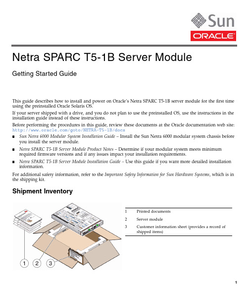
This guide describes how to install and power on Oracle’s Netra SPARC T5-1B server module for the first time using the preinstalled Oracle Solaris OS.If your server shipped with a drive,and you do not plan to use the preinstalled OS,use the instructions in the installation guide instead of these instructions.Before performing the procedures in this guide,review these documents at the Oracle documentation web site:/goto/NETRA-T5-1B/docs■Sun Netra 6000Modular System Installation Guide –Install the Sun Netra 6000modular system chassis beforeyou install the server module.■Netra SPARC T5-1B Server Module Product Notes –Determine if your modular system meets minimum required firmware versions and if any issues impact your installation requirements.■Netra SPARC T5-1B Server Module Installation Guide –Use this guide if you want more detailed installation information .For additional safety information,refer to the Important Safety Information for Sun Hardware Systems ,which is in the shipping kit.Shipment Inventory1Printed documents 2Server module 3Customer information sheet (provides a record ofshippeditems)Netra SPARC T5-1B Server ModuleGetting Started Guide▼Install Optional Components♦Before installing the server module into the chassis,install any optional internal components that you plan to use with the server module.For instructions on installing optional components,refer to the documentation for each component and to the Netra SPARC T5-1B Server Module Service Manual.▼Install the Server Module Into the ChassisThe server module is hot-pluggable in the chassis.The instructions in this guide assume that the Sun Netra 6000modular system is installed,and is up and running.Caution–Due to cooling restrictions,you must install the server module into the chassis within60 seconds of removing the filler panel.1.Unpack the server module.2.Remove the protective connector cover from the rear of the server module.3.Remove the filler panel from the desired server module slot in the chassis.4.With the ejector levers on the right,insert the server module into the chassis(panel1)until it is about1.5cm(.5in.)from the front of the chassis.5.Pinch the ejector levers to open them(panel2).6.Push the server module into the chassis and close the ejector levers(panel3).7.Verify the server module insertion(panel4)by checking the green OK LED on the server module.When the server module is plugged in,standby power is supplied to the service processor(SP).After about 10seconds,the front panel LEDs blink three times,then the green OK LED blinks for a few minutes.The server module SP generates messages as soon as the server module is connected to a powered modular▼Determine Your Connection MethodUse the Oracle Integrated Lights Out Manager(Oracle ILOM)software that runs on the server module SP to start,boot,and manage the server module.You can access the SP in several ways as shown in the following figure.♦Connect to the server module using one of the methods shown in the following figure and table.This guide describes methods1and2,but you can use other methods as described in the Netra SPARC T5-1B Server Module Installation Guide.Method Connection Requirements1EthernetFrom:CMM NET MGT portTo:Your network •Know the IP address of the CMM.•Know the CMM Oracle ILOM user and password account information. Note–You can use the CMM Oracle ILOM web interface or CLI.See“Method1–Power On the Host Through the CMM(Web Interface)”on page4.2SerialFrom:Server module SP UCP portTo:Terminal device •A terminal device and serial cable•Dongle cableNote–You communicate directly with the server module SP using the Oracle ILOM CLI.See“Method2–Power On the Host Through the Front Panel(SP CLI)”on page4.3SerialFrom:CMM SER MGT portTo:Terminal device •A terminal device and serial cable•Know the CMM Oracle ILOM user and password account information. Note–You communicate through the CMM using the Oracle ILOM CLI. Refer to the Netra SPARC T5-1B Server Module Installation Guide forinstructions.▼Method1–Power On the Host Through the CMM(Web Interface)In this procedure,you use the CMM Oracle ILOM3.1or3.2.1web interface to access the server module SP.If your CMM is instead running Oracle ILOM3.0,refer to the Oracle ILOM3.0documentation.1.Ensure that the CMM NET MGT port is connected and configured to communicate on your network.Refer to the modular system documentation for details.2.Access the Oracle ILOM web interface on the CMM.In a browser on the same network as the modular system,type:http://cmm_ip_addresswhere cmm_ip_address is your CMM IP address.The Oracle ILOM login page is displayed.3.Log into Oracle ILOM on the CMM by typing your user name and password.The factory default Oracle ILOM root password is changeme,but might have been changed in your environment.4.In the upper left corner of the window,change Manage Chassis to Manage Blade n,where n is the slot inwhich the blade is installed(starting from0).5.In the Actions panel next to Power State,click the Turn On button.6.Click OK to confirm the power on action.7.In the left navigation panel,click on Remote Control>Redirection.8.Select Use serial redirection,and click Launch Remote Console.If your server module has a drive,the host boots from the preinstalled OS.Messages are displayed in the host console.When the booting completes,you are automatically prompted for Oracle Solaris OSconfiguration information.Go to“Set Up the Operating System”on page5.▼Method2–Power On the Host Through the Front Panel(SP CLI)In this procedure,you use a dongle cable to connect directly to the front of the server mands are performed using the Oracle ILOM CLI.1.Connect the dongle cable to the UCP port on the server module front panel.A dongle cable is provided with each modular system(chassis).The dongle cable is intended for temporary installation and configuration.2.Configure and connect a terminal device to the serial connector on the dongle cable.On UCP-3dongles,use the RJ-45serial connector.On UCP-4dongles,use the DB-9serial connector.Set up the terminal device for8bits,no parity,1stop bit,9600baud rate,and no flow control.The Oracle ILOM login prompt is displayed on the terminal.3.Enter the following factory default user name and password:■User name:root■Password:changemeYou are now logged into Oracle ILOM on the server module SP.4.Power on the server module and start the host console.The server module initializes.If your server module has a drive,the host boots from the preinstalled OS.Messages are displayed in the host console.When the booting completes,you are automatically prompted for Oracle Solaris OSconfiguration information.▼Set Up the Operating SystemIf a local boot device is accessible and if the Oracle Solaris OS is preinstalled,you are prompted for OS configuration information in the host console.Otherwise,the host seeks a boot device on the network.♦Configure the preinstalled OS or reinstall a supported OS to suit your needs.For details on the Oracle Solaris OS configuration process,refer to the Netra SPARC T5-1B Server Module Installation Guide and the installation guides for your version of the Oracle Solaris OS.Note –Consider using Oracle VM Server.Oracle VM Server is a preinstalled system virtualization feature that provides a discrete logical grouping with its own operating system,resources,and identity within a singlecomputer system.You can run a variety of applications in different logical domains and keep them independent for performance and security purposes.▼Check for the Latest OS Updates,Patches,and FirmwareSome server module features are enabled only when certain updates,patches,or firmware versions are installed.Install the latest available versions for the best performance,security,and stability.1.Review the Netra SPARC T5-1B Server Module Product Notes.See “Related Documentation”on page 6.This document describes important product dependencies and late-breaking information.2.Download the latest available versions from My Oracle Support at:https:// ->start /SystemAre you sure you want to start /System (y/n)?y->start /HOST/consoleAre you sure you want to start /HOST/console (y/n)?ySerial console started. To stop, type #.Related DocumentationFeedbackProvide feedback on this document at:/goto/docfeedbackSupport and AccessibilityOracle customers have access to electronic support through My Oracle Support.For information visit /pls/topic/lookup?ctx=acc&id=infoor visit /pls/topic/lookup?ctx=acc&id=trs if you are hearing impaired.Documentation LinksAll Oracle products Netra SPARC T5-1B server module/goto/NETRA-T5-1B/docs Sun Netra 6000modular system/goto/SN6000/docs Oracle ILOM/goto/ILOM/docs Oracle Solaris 11OS/goto/Solaris11/docs Oracle Solaris 10OS/goto/Solaris10/docs Oracle VM for SPARC /goto/VM-SPARC/docsCopyright ©2013,Oracle and/or its affiliates.All rights reserved.Copyright ©2013,Oracle et/ou ses affiliés.Tous droits réservés.Part Number: E35779-01Mfg. Number: 7054460April 2013。
Backup Box-(B0, B1) 快速安装指南说明书

Backup Box-(B0, B1) Quick GuideIssue: 04Date: 2023-02-1511.The information in this document is subject to change without notice. Every effort has been made in the preparation of this document to ensure accuracy of the contents, but all statements, information, and recommendations in this document do not constitute a warranty of any kind, express or implied.2.Before installing the device, read the user manual carefully to get familiar with product information and safety precautions.3.Only certified electricians are allowed to operate the device. Operation personnel must wear proper personal protective equipment (PPE).4.Before installing the device, check that the package contents are intact and complete against the packing list. If any item is missing or damaged, contact your dealer.5.The device damage caused by the violation of instructions in this document is not covered under warranty.6.The cable colors involved in this document are for reference only. Select cables in accordance with local cable specifications.FunctionThe Backup Box is used in a residential rooftop PV plant system to control the inverter grid-tied or off-grid state. When the grid fails, the inverter switches to the off-grid state and supplies power to off-grid loads in backup mode. When the grid recovers, the inverter switches back to the grid-tied state.Model NumberNo.Meaning Value1Product name Backup Box: Backup Box 2Design codeB0: single-phase B1: three-phaseSystem NetworkingThe grid-tied system of a rooftop PV plant consists of PV strings, an energy storage system (ESS),an inverter, a Backup Box, a management system, an AC switch, and a power distribution unit.Supported Grid TypesThe Backup Box supports the following grid types: TN-S, TN-C-S and TT. When the inverter is inthree-phase, three-wire mode, the Backup Box does not support off-grid operation.•Off-grid electric motor loads are not supported. The startup power of an electric motor is several times of its rated power, which may exceed the load capacity of the Backup Box, resulting in startup failure.•The off-grid load port cannot be directly connected to the power grid. Otherwise, the off-grid function is unavailable, causing shutdown upon overload.•The power of off-grid loads cannot exceed the maximum off-grid output power of the inverter.Appearance(1) Front panel(2) Lock(3) Hanging kit(4) Off-grid load port (BACKUP LOAD)(5) Grid AC port (GRID)(6) Inverter AC port (INVERTER AC)(7) COM port (COM)(8) Ventilation valve(9) Ground point(10) Off-grid load switch3Installation Space Angle1.When a Backup Box is installed outdoors, avoid direct sunlight. You are advised to install it in a sheltered place or install an awning over it.2. A surge protective device (SPD) needs to be installed on the grid side of the Backup Box.Installation Requirements2.12Mounting Holes and DimensionsWhen drilling holes, avoid the water pipes and power cables buried in the wall.Installing a Backup Box2.2⚫M6x60 expansion bolts are delivered with the Backup Box. If the length and number of the bolts do not meet installation requirements, prepare M6 stainless steel expansion bolts by yourself.⚫The expansion bolts delivered with the inverter are mainly used for solid concrete walls. For other types of walls, prepare bolts by yourself and ensure that the wall meets the load bearing requirements of the inverter.⚫In residential areas, do not install the inverter on drywalls or walls made of similar materials which have a weak sound insulation performance because the noise generated by theinverter is noticeable.LevelPreparations3.1⚫Connect cables in accordance with local installation laws and regulations.⚫Before connecting cables, ensure that the circuit breaker on the Backup Box and all the switches connecting to the Backup Box are set to OFF position. Otherwise, the high voltage of the Backup Box may result in electric shocks.⚫After opening the device panel of the Backup Box, remove the shockproof foam. Otherwise, the circuit breaker cannot work properly.⚫If the external AC switch can perform earth leakage protection, the rated leakage action current should be greater than or equal to 100 mA.⚫If multiple SUN2000s connect to the general residual current device (RCD) through their respective external AC switches, the rated leakage action current of the general RCD should be greater than or equal to the number of SUN2000s multiplied by 100 mA.⚫The rated input voltage of the Backup Box is 220 V/230 V (single-phase) or 380 V/400 V (three-phase). If the device runs in a weak power grid area, a self-recoveryovervoltage/undervoltage protector needs to be installed at the upstream of the X2 AC power grid input terminal of the Backup Box. This ensures that the device can bedisconnected from the power grid when the power grid voltage is abnormal, preventing damage.3No.Cable Type Conductor Cross-Sectional Area RangeOuter Diameter1PE cable Single-core outdoorcopper cable4–10 mm2N/A2Off-grid loadoutput power cableOutdoor copper cable4–6 mm210–21 mm3Grid AC outputpower cableOutdoor copper cable4–6 mm210–21 mm4Inverter AC inputpower cableOutdoor copper cable4–6 mm210–21 mm5Signal cable Two-core outdoorshielded twisted paircable0.20–1 mm24–8 mmPrepare cables based on site requirements.Installing an Output Power Cable for Off-Grid Loads3.3X1Before installing a cable, open the panel of the Backup Box, route the cable through the off-gridload port, and connect the cable. After all cables are connected, reinstall the panel.Off-Grid Load Terminal (X1)No..1234Single-PhaseLN-PEOff-Grid Load Terminal (X1)No..1234Three-Phase LN-PEStrip the cable to the wiring portInstalling a PE Cable3.2Do not connect the neutral wire to the enclosure as a PE cable. Otherwise, electric shocks mayoccur.Ground pointIf multiple inverters are connected in parallel, the connection of AC power cables L1, L2, and L3 on the power grid side of the Backup Boxes connected to each inverter must be the same.Installing an Inverter AC Input Power Cable3.5X2Connecting AC Input Terminals of the Inverter (X3)No.1234567891011Single-Phase-L---N---PE-Connecting AC Input Terminals of the Inverter (X3)No.12345678910111213Three-PhaseL1-L2-L3--N---PE-Strip the cable to the wiring portInstalling a Grid AC Output Power Cable3.4Connecting Grid AC Terminals (X2)No.1234567Single-PhaseL--N-PE-Connecting Grid AC Terminals (X2)No.1234567Three-PhaseL1L2L3N-PE-The sequence of connecting the cables to a single-phase Backup Box and to the AC terminals L, N, and PE on the inverter must be the same. The sequence of connecting the cables to a three-phase Backup Box and to the AC terminals L1, L2, and L3 on the inverter must be the same. Otherwise, the device cannot work properly. (As shown in the following figures, connect the cables to a single-phase Backup Box in the sequence of L, N, and PE from left to right, and connect the cables to a three-phase Backup Box in the sequence of L1, L2, and L3.)Backup Box-side terminal (single-phase)Inverter-side terminal (single-phase)X3Backup Box-side terminal (three-phase)Inverter-side terminal (three-phase)Strip the cable to the wiring portbel Definition Note1DIDigital input signal+Connects to the positive pole of the DI port and functions as the port for the Backup Box to send feedback signals.2GND GND of the DI portConnects to the GND of the DI port.Communications Terminal DefinitionInstalling Signal Cables3.7Neutral Wire DisconnectedIf the neutral wire needs to be disconnected in off-grid mode (such as in German), according to the local power grid standard, insert the short-circuiting plate between 10 and 11 of the AC terminal X3for the single-phase Backup Box. Insert the short-circuiting plate between 12 and 13 of the AC terminal X3 for the three-phase Backup Box.Power grid AC terminal X2 (Single-Phase/Three-Phase)Inverter AC terminal X3 (single-phase)Inverter AC terminal X3 (three-phase)Neutral Wire ConnectedIf the neutral wire cannot be disconnected from the power grid in off-grid mode (such as in Australia), insert the short-circuiting plate between 4 and 5 of the AC terminal X2 according to the local power grid standard.•When installing a short-circuiting plate, ensure that it is inserted into the correct port andsecurely installed to avoid short circuits caused by incorrect installation.•If no short-circuiting plate is installed, the neutral wire will be suspended in off-grid mode, but the off-grid/grid-tied switching function is not affected. You are advised to install ashort-circuiting plate according to the local power grid standard.Installing a Short-Circuiting Plate3.6The short-circuiting bar delivered with the product is bound to the ground cable inside the chassis.Inverter ACCOM port (COM)COM Port Pin Definitionsbel Definitio n Description 5GNDGNDConnects to the GND of the DI2 port.8DI2Digital input signal 2+Connects to the positive terminal of DI2 and functions as the port for the Backup Box to send feedback signals.3.8Connecting Signal Cables on the Inverter SideSUN2000-(2KTL-6KTL)-L1X4Strip the cable tothe wiring portSUN2000-(3KTL-12KTL)-M1COM port (COM)bel Definition Note8DIN1Digital inputsignal 1+Functions as the port for the Backup Box to send feedback signals.16GNDGNDConnects to the GND of DIN1.COM Port Pin DefinitionsInverter AC4No.Acceptance Criteria1The installation is correct and reliable.2Cables are routed properly as required by the customer.3Cable ties are secured evenly and no burr exists.4The PE cable is connected correctly, securely, and reliably.5The switch of the Backup Box and all the switches connected to it are OFF.6Cables are connected correctly and securely. Use a phase sequence meter to check whether the cables on the grid side are connected correctly.7Unused terminals and ports are locked by watertight caps.8The installation space is proper, and the installation environment is clean and tidy.5Powering On the Systeme a multimeter to check whether the AC voltage in the power distribution box (PDB) is within the allowed range and whether cables are correctly connected.2.Turn on the PDB AC switch between the Backup Box and the power grid. (Ensure that the load switch of the Backup Box is OFF.)3.Check whether the cable connection of the grid AC terminals is correct.4.(Optional) Remove the locking screw beside the DC switch on the inverter.5.Turn on the DC switch (if any) between the PV strings and the inverter.6.Turn on the DC switch at the bottom of the inverter.7.Check that the off-grid load power does not exceed the off-grid output power allowed bythe inverter.8.After ensuring that the load circuit is normal, turn on the AC switch of the Backup Box.9.Observe the LED indicators on the front of the inverter to check the running status of the inverter.Parameter SettingsOpen the FusionSolar app, log in to using the installer account, choose My > Device Commissioning , and connect to the WLAN hotspot of the solar inverter.On the home page, choose Setting > Feature parameters to set the off-grid/grid-tied control parameters.6System CommissioningDownload and install the latest version of the FusionSolar app by referring to the quick guide for the corresponding inverter model or the FusionSolar App Quick Guide . Register an installer account and create a plant and owner (skip this step if an account has been created). You can scan the QR code to obtain the FusionSolar App Quick Guide .During system deployment, the AC power supply needs to be connected to ensure that the off-grid/grid-tied switching function of the Backup Box can be verified.Category Status (Blinking orange at long intervals, On for 1s and then Off for 1s)Definition Running indicationN/A Steady green Steady green On-grid Steady orangeSteady orangeBackupBlinking orange at long intervalsOffStandby in backup modeBlinking orange at longintervalsBlinking orange at longintervalsOverload in backup mode If the off-grid load is overloaded, indicators and on the inverter blink orange slowly. Reduce the off-grid load power and manually clear the alarm or until the inverter is recovered. The inverter attempts to restart at an interval of 5 minutes. If the inverter fails to restart for three times, the interval changes to 2 hours. If the inverter is standby in off-grid mode, check the inverter alarms and rectify the fault.8Troubleshooting7Routine MaintenanceTo ensure the long-term and proper running of the system, you are advised to perform routine maintenance on the Backup Box periodically.1. Check the system cleanliness, system running status, electrical connection, and grounding reliability every half year.2. Check whether the off-grid/grid-tied switching function is normal each quarter.1.Backup Box checking solution:After arriving at the site, the personnel can check whether the Backup Box is damaged as follows:Parameter SettingsValueOff-grid modeIf this parameter is enabled, the Backup Box switches to the off-grid mode when the grid fails. This parameter can be set only when the Backup Box is configured. If the Backup Box is not configured, this parameter cannot be enabled. Otherwise, an alarm is generated.⚫Enable ⚫Disabled (default)Backup power SOC Sets the backup power SOC. In grid-tied mode, the battery does not discharge when it is discharged to the backuppower SOC. When the grid fails, the battery supplies power to loads in off-grid mode until it reaches the end-of-discharge capacity.[20%, 100%]Default value: N/AGrid-tied/Off-grid mode switchingIf this parameter is set to Automatic switching, the system switches to the off-grid mode when the grid fails, and switches to the grid-tied mode when the grid recovers.If this parameter is set to Manual switching, you need to log in to the app and connect the inverter to enable the off-grid mode when the grid fails.⚫Automatic switching (default)⚫Manual switching1.Power on the Backup Box according to the power-on procedure, wait for the inverter to connect to the power grid, and log in to the app to enable Off-grid mode .2.Turn off the AC switch in the PDB between the Backup Box and the power grid, and check whether the off-grid output is normal. The inverter indicators and are steadyorange. (If the AC switch between the inverter and the Backup Box is turned off, the off-grid switching is not triggered and the inverter is in off-grid standby mode.)3.Turn on the AC switch in the PDB between the Backup Box and the power grid. The inverter indicators and blink green slowly until the inverter is connected to the power grid.Verifying the Off-grid/Grid-tied Switching Functiona.It is recommended that loads be disconnected before checking.e a multimeter to check the connectivity between the Backup Box terminals, as shown in the following tables.9 c.If the conduction status of an item is inconsistent with that in the tables, the Backup Box is damaged.Three-Phase Backup Box2.If the mains recovers but the inverter still works in off-grid state (LED1 and LED2 are steady orange), contact the customer service personnel or dealer for repair.3.If the off-grid mode is enabled when no Backup Box is connected, an alarm indicating that the Backup Box is abnormal is reported when the AC power supply is disconnected. In this case, the fault cannot be rectified. The fault is rectified only after the inverter and battery are powered off.4.If the Backup Box is used for the first time and is not used later, you must disable the off-grid mode when the inverter is running properly. Otherwise, you need to power on the inverter again and modify the settings.5.If the single-phase Backup Box generates abnormal noises during repeated switching, check whether the inverter AC terminal is reversely connected to the power grid AC terminal.6.If the AC contactor KM3 of the Backup Box repeatedly switches on and off and generates abnormal sound, check whether the off-grid load is too high.No.Wiring RequirementsDetection TerminalCircuitBreaker (QF)Grid InverterX4-1 & X4-2COM-1& COM-2X2-1 & X3-2GRID-L & INVERTER-LX3-6 & X3-10INVERTER-N&INVERTER-PEX2-1 & X1-1GRID-L &LOAD-LX3-6 & X1-2INVERTER -N& LOAD-N1OnPoweroffShutdownConnected Disconnected Disconnected DisconnectedConnected2On PoweronShutdownDisconnected Connected Disconnected Connected Connected 3OnPower off Off-grid outputConnectedDisconnectedConnectedDisconnectedConnectedSingle-Phase Backup BoxNo.Wiring Requirements Detection Terminal CircuitBreake r (QF)Grid InverterX4-1 & X4-2COM-1& COM-2X2-1 & X3-1GRID-L1& INVERTER-L1X3-3 & X3-8INVERTER-L2& INVERTER-N X2-1 & X1-1GRID-L1& LOAD-LX3-3 & X1-2INVERTER-L2& LOAD-N1On PoweroffShutdown ConnectedDisconnectedDisconnected Disconnected Disconnected 2On PoweronShutdown Disconnected ConnectedDisconnected ConnectedDisconnected3OnPower off Off-grid outputConnectedDisconnectedConnectedDisconnected Connected9Customer Service ContactRegion Country Service Support Email PhoneEurope France******************************0080033888888 GermanySpainItalyUKNetherlandsOther countries For details, see .Asia Pacific Australia******************************1800046639Turkey******************************N/AMalaysia********************0080021686868/1800220036Thailand(+66) 26542662 (chargedby local call)1800290055 (free inThailand)China***********************400-822-9999Other countries********************0060-3-21686868Japan Japan*******************.com0120258367 India India******************************180****8009 South Korea South Korea*******************.com N/ANorth America USA******************************1-877-948-2934 Canada******************************1-855-482-9343Latin America Mexico******************************018007703456/0052-442-4288288 Argentina0-8009993456Brazil0-8005953456Chile800201866 (only for fixed) Other countries0052-442-4288288Middle East and Africa Egypt*****************************************/0020235353900 UAE*********** South Africa0800222900 Saudi Arabia8001161177 Pakistan0092512800019 Morocco0800009900 Other countries0020235353900。
安装配置用户手册

综合平台及物料平衡安装配置手册目录综合平台及物料平衡 (1)安装配置手册 (1)第一章前言 (3)第二章系统配置要求 (4)2.1 系统软件要求 (4)2.2 系统硬件要求 (5)2.3 安装之前的检查 (6)第三章安装环境 (8)3.1 IIS 安装 (8)3.2dotnetfxchs安装 (10)3.3 数据库环境 (10)3.4 综合展示环境 (13)3.5 物料平衡运行环境 (20)第四章综合平台安装与配置................................................................. 错误!未定义书签。
4.1 综合平台安装 ......................................................................... 错误!未定义书签。
4.2 修改所有已安装软件的Web.config文件 ........................... 错误!未定义书签。
4.3 配置综合平台 ......................................................................... 错误!未定义书签。
4.3 配置综合展示 ......................................................................... 错误!未定义书签。
4.4 配置自定义工作台 ................................................................. 错误!未定义书签。
4.5 配置XMES............................................................................. 错误!未定义书签。
Motor Driver HAT 用户手册说明书

Motor Driver HAT用户手册产品概述Motor Driver HAT是专为树莓派控制电机而设计的,使用I2C接口控制,适用于驱动小车电机。
特点⚫基于树莓派接口设计,适用于Raspberry Pi Zero/Zero W/Zero WH/2B/3B/3B+⚫I2C接口控制,通过改变5个地址跳线可以同时接多达32个模块⚫板载PCA9685芯片,可输出12位硬件PWM控制电机转速⚫板载TB6612FNG双H桥电机驱动芯片,工作高效,不易发热⚫板载5V稳压芯片,输出可达3A电流,可通过VIN端子接入电池供电⚫预留I2C控制接口,方便接入其他主控板⚫提供完善的配套资料手册(提供BCM2835、wiringPi与python例程)产品参数供电电压:6V ~ 12V(VIN端子)逻辑电压: 3.3VPWM驱动芯片:PCA9685PWM芯片接口:I2C电机驱动芯片:TBA6612FNG产品尺寸:65mm x 30mm固定孔通径: 3.0mm接口说明模块实物图如下:硬件资源硬件上实际上由三部分构成:电源、PWM、电机驱动电源输入端采用MP1584稳压芯片,该芯片支持4.5V到28V的宽电压输入,输出电流达3A。
虽然芯片支持最高28V的输入,但是由于给电机的工作电压也由VIN_USER供给,实际上输入电压最好保持在6-12V.MP1584稳压芯片输出5V,这个5V用于给树莓派供电,然后5V再通过RT9193-33转成3.3V电平,该电平给PWM、电机驱动这两部分提供逻辑电压PWM由于树莓派硬件PWM只有一个引脚GPIO.1,而且,虽然wiringPi库与python都有软件PWM,但是会占用部分CPU资源,因此本模块采用PCA9685芯片,该芯片使用I2C控制,可输出16路12位分辨率的PWM,可控制输出频率40HZ-1000HZ。
操作简单,只需要给芯片控制对应寄存器的值,即可一直输出PWM信号。
根据上面的原理图,我们可以看出LED0-LED5为控制电机驱动芯片管脚。
RKNN-Toolkit 使用指南
RKNN-Toolkit 使用指南V1.1.0T oy br ic kc on f id en t ia目 录1 主要功能说明 ............................................................................................................................................. 12 系统依赖说明 ............................................................................................................................................. 2 3使用说明 ..................................................................................................................................................... 3 3.1安装 (3)3.1.1 通过pip install 命令安装 .......................................................................................................... 3 3.1.2 通过DOCKER 镜像安装 . (4)3.2RKNN-T OOLKIT 的使用 (5)3.2.1 场景一:模型运行在PC 上 ..................................................................................................... 5 3.2.2 场景二:模型运行在与PC 相连的RK3399Pro 、RK1808或RK1808计算棒上 .. (8)3.2.3 场景三:模型运行在RK3399Pro Linux 开发板上 (9)3.3混合量化 (9)3.3.1 混合量化功能用法 (9)3.3.2 混合量化配置文件 .................................................................................................................. 10 3.3.3混合量化使用流程 (11)3.4 示例 .................................................................................................................................................. 12 3.5API 详细说明 (15)3.5.1 RKNN 初始化及对象释放 (15)3.5.2 模型加载 (16)3.5.3 RKNN 模型配置 (19)3.5.4 构建RKNN 模型 ...................................................................................................................... 20 3.5.5 导出RKNN 模型 ...................................................................................................................... 21 3.5.6 加载RKNN 模型 ...................................................................................................................... 22 3.5.7 初始化运行时环境 .................................................................................................................. 22 3.5.8使用模型对输入进行推理 (23)T oy br ic kcon f id en t ia3.5.9 评估模型性能 .......................................................................................................................... 25 3.5.10 获取内存使用情况 .................................................................................................................. 28 3.5.11 查询SDK 版本 ......................................................................................................................... 30 3.5.12 混合量化 .................................................................................................................................. 30 3.5.13获取设备列表 (32)T oy br ic kc on f id en t ia1 主要功能说明RKNN-Toolkit 是为用户提供在PC 、RK3399Pro 、RK1808、TB-RK1808 AI 计算棒或RK3399Pro Linux 开发板上进行模型转换、推理和性能评估的开发套件,用户通过提供的python 接口可以便捷地完成以下功能:1)模型转换:支持Caffe 、TensorFlow 、TensorFlow Lite 、ONNX 、Darknet 模型转成RKNN 模型,支持RKNN 模型导入导出,后续能够在硬件平台上加载使用。
foxboro工程师手册

I/A’s系统维护手册(工程师手册)编制:何卫兵上海福克斯波罗有限公司二零零二年元月第一章系统概述本手册为上海福克斯波罗有限公司DCS系统I/A维护手册,并作为I/A’s 培训手册的补充。
用户可以结合两本手册来进行系统操作、软件组态及系统维护。
必要时还应参考随机的原版资料及福克斯波罗公司提供的中文培训手册。
本手册针对福克斯波罗制造的I/A’S,采用Solaris 2.5.1操作系统和I/A’s 6.2.1版本应用软件。
整个系统为一个节点,在冗余的节点总线DNBI上挂有:●三台工程师站AW5101、AW5102、AW5103该站作为工程师站,内置256M内存及8GB硬盘,AW5102外挂一台喷墨打印机(电缆长度15米),AW5103配有和MIS系统通讯用的第二以太网卡。
该工作站安放在工程师站内,与I/A机柜(位于电子间)之间的通讯电缆长度为30米。
●四台操作员站WP5101、WP5103、WP5104、WP5105该站内置128M内存及8GB硬盘,并各配有一个21”的CRT。
该工作站安放在主控室内与I/A机柜(位于电子间)之间的通讯电缆长度为30米。
●一台操作员站WP5102该站作为大屏幕操作站,内置128M内存及8GB硬盘,除配有一个21”的CRT外。
还配有一台用于显示大屏幕的以太网卡。
该工作站安放在主控室内,与I/A机柜(位于电子间)之间的通讯电缆长度为30米。
●十一对容错台控制处理站CP4001、CP4002、CP4003、CP4004、CP4005、CP4006、CP4007、CP4008、CP4009、CP4010、CP4011此容错型控制处理站CP40BFT,用于实现DCS系统的数据采集及控制。
该控制处理器安放在电子间内。
现场由十八个装有现场总线组件FBM的现场机柜、十个安装DCS系统辅助装置(包括冗余的24VDC电源、交流继电器、直流继电器、SIMENSE交流接触器、以及相应的I/O端子)的继电器柜、一个DCS系统220VAC配电柜共同构成。
博世Robert Bosch GmbH BVMS - 配置 Microsoft iSCSI 目标说明
BVMS - Configuring Microsoft iSCSItargetAuthor: Verhaeg Mario (BT-SC/PAS4-MKP)Date: 19 February, 2020BVMS - Configuring Microsoft iSCSI target 2 of 171Document information 3 1.1Version history 3 2Introduction 4 3Microsoft iSCSI Target 5 4Configuration 6 4.1Install the iSCSI target 6 4.2Configure the iSCSI target7 4.3Configuration using Powershell 10 4.4BVMS configuration 10 4.5Storage system13 5Troubleshooting 14 5.1Video Recording Manager 14 5.2Windows Resource Monitor. 15 5.3Hardware specific tools15 6After-sales support 16 7External information 171 Document informationProject BVMS 10.0.1Reference n/aVersion22Last modified19 February 20201.1 Version historyVersion Date Who Description 2219 February 2020Mario Verhaeg Release.2 IntroductionSCSI (Small Computer System Interface) is most commonly used for the communication between computers and peripheral devices, such as hard drives. iSCSI enables devices to use SCSI over a network interface, therefore it makes a lot of sense for cameras to use iSCSI to record video. The camera is a small computer that needs a (network) connection to a "hard drive" to store video footage. In other systems this job is performed by the network video recorder (NVR).Image: Network Video Recorder versus Bosch iSCSI based storage. The Storage Area Network (SAN) could also beiSCSI based.A network video recorder introduces a single point of failure: all video streams are being processed by a single software process. When this process fails (hardware failure, software crash) a standby network video recorder can connect to those cameras and take over the recording process. This process consumes some time and will result in a small recording gap. A network video recorder does not exist in a Bosch environment. However, there is one exception: when non-Bosch cameras are used a network video recorder called Video Streaming Gateway is used to record streams from these cameras onto the iSCSI environment.Microsoft Server Windows 2016This guide is based on Microsoft Windows Server 2012 R2. Microsoft did not make major changes in thetransition to Windows Server 2016 or Windows Server 2019. This guide could therefore also be used as a guide for Windows Server 2016 or Windows Server 2019.3 Microsoft iSCSI TargetThe Microsoft iSCSI target is part of all Windows Server editions. It will pick-up the iSCSI traffic coming from the camera and will write it the storage device. This storage device can be connected to a storage area network, but can also reside within the same system as local hard drives.Since Windows Server 2012 R2 the iSCSI target support up to 544 iSCSI sessions (source: Microsoft Technet - iSCSI Target Server Scalability Limits). For fail-over purposes and, depending on the configuration, a camera connects to an active iSCSI target and a passive iSCSI target simultaneously. Bosch recommends to allocate up to 256 cameras to a single Microsoft iSCSI target based on Windows Server 2012 R2.4 Configuration4.1 Install the iSCSI targetCheck if the Role "File and Storage Service iSCSI Target Server" is installed. Start the "Server Manager". This will start the "Add Roles and Features Wizard". Click "Next".Choose the "Role-based or feature-based installation" option.Select the system on which the iSCSI target needs to be installed (normally this would be the local system on which the wizard is started).Windows Advanced FirewallBefore starting the configuration, the Windows Advanced Firewall needs to allows iSCSI traffic to pass. Microsoft Technet - Configuring Windows Firewall for iSCSI Software Targetdescribes how to achieve this.Check of iSCSI target Server is installed. If not installed, select iSCSI Target server and install the role.4.2 Configure the iSCSI targetThe iSCSI target server uses virtual disks, which are assigned to an iSCSI target. The virtual disks are used forrecordings of cameras. The size of the virtual hard disks represent the size of LUN’s assigned to the VRM. Boschrecommends to use a maximum LUN size of 2 Terabyte. A single Video Recording Manager can handle up to 2 Petabyte. If more storage is required, another Video Recording Manager needs to be added.To start the configuration, open the Windows 2012 Server Manager, select "File and Storage Services" and click "iSCSI".Configure storage deviceBefore continuing with this guide, the (optional) storage arrays need to be configured and connected to theWindows operating system. This means the arrays should have a drive letter assigned to them. As this process is different for each and every storage vendor, Bosch recommends to contact the storage vendor for documentationregarding this process.Start the wizard: “To create an iSCSI virtual disk, start the New iSCSI Virtual Disk Wizard”. Select the volume to create new virtual hard disks.On this server the F drive is used to create the virtual disks. In the next step, the disk name needs to be specified.Define the size of the virtual hard disk, minimum 200 GB and maximum 2048 GB and make sure “clear the virtual hard disk on allocation” is checked. Multiple disks need to be created if the storage capacity of the system exceeds 2048 GB. One iSCSI target can contain multiple disks. Each disk will be represented as a LUN.When a new system is created: create a new iSCSI target and define the name of the target. When a new virtual disk is added to an existing system: select the iSCSI target to which the disk needs to be added.In the "Target name and Access" window the access to the target is specified. We recommend you to configure an IQN or IP based filter that ensures only the whitelisted devices have access to the iSCSI target. For demonstration purposes the "*" can be used in the IQN filter to whitelist all devices.CHAP authentication is supported and can be enabled as required. The Video Recording Manager and cameras (described in their respective manuals) need to have a matching configuration.Finish the wizard.4.3 Configuration using Powershell#create targetNew-IscsiServerTarget TG0 -InitiatorID Iqn:*$disk = Get-WmiObject Win32_LogicalDisk -Filter"DeviceID='D:'" | Select-Object Size,FreeSpace #calculate how many vhdx files to create and then do it in a loopWrite-Host"total space on volume in bytes "$disk.SizeWrite-Host"free space on volune in bytes "$disk.FreeSpace$freeSpaceInMB = [int]($disk.FreeSpace / (1024 * 1024))Write-Host"free in MB "$freeSpaceInMB$lunSizeInMB = 1950 * 1024$lunCount = [int]($freeSpaceInMB / $lunSizeInMB)For($i=0; $i-lt$lunCount; $i++) {$currentFileName = ("vhd_" + $i + ".vhdx")New-IscsiVirtualDisk-DevicePath$currentFileName-Size$lunSizeInMB"MB"-fixed-DoNotClearDataAdd-IscsiVirtualDiskTargetMapping-TargetName TG0 -DevicePath$currentFileName}4.4 BVMS configurationWhen adding a new storage device to the BVMS (as described in the BVMS configuration manual) some parameters are required.Specify the values as required, and use a Windows user-name and password which has administrative access on the iSCSI server.Activate the configuration before making further changes.The target needs to be scanned once the target configuration is activated.After adding the iSCSI device an error message could pop up. This message indicates the current file format on the LUNis not recognized and it needs to be formatted. Click "OK".WarningWhen the BVMS Config Client is not able to scan the iSCSI target, it is most likely the selected user accountdoes not have the rights to provide the BVMS with the correct information. Ensure that the Windows user is partof the "administrators" group. A description on how to do this can be found on Microsoft Technet - Add a memberto a local group .Select the LUN(s), and click "Format LUN".As this will be a new system no data is currently stored on the LUNs, the warning message can be accepted.1.2.3.Right click on the iSCSI device, and click "Load balancing". Set the upper limits for the permitted bit rate and the number of simultaneous iSCSI connections for each iSCSI system. If these limits are exceeded, data is no longer being written to the iSCSI system and is lost.4.5 Storage systemAs storage systems from different vendors differ in configuration, the specific configuration details are not in the scope of this document. Some general recommendations regarding the configuration of a storage system are given.4.5.1 CacheThere are three main caching techniques that can be deployed:Write-through cache: directs write I/O onto cache and through to underlying permanent storage before confirming I/O completion to the host.Write-around cache: write I/O is written directly to permanent storage, bypassing the cache.Write-back cache: write I/O is directed to cache and completion is immediately confirmed to the host: this is therecommended way of writing for video footage.PerformanceThe load balancing limits are very important: If the storage device cannot offer the performance which isconfigured, recording gaps might appear and cameras might loose connections to the storage device.5 TroubleshootingRecording gaps and camera disconnect messages can appear if the storage system experiences problems, or is overloaded.5.1 Video Recording ManagerThe Bosch Video Recording Manager included a lot of tools to evaluate the performance of the system and analyse problems. The Video Recording Manager dashboard can be opened by browsing to the IP address on which the Video Recording Manager is installed. Alternatively the Video Recording Manager dashboard can be opened by right-clicking on the Video Recording Manager in the BVMS Config client, and clicking "VRM monitor".The Targets page (under Storage), shows the individual targets and their status.The Storage Overview page shows the total consumes bandwidth and system capacity.The System Logbook shows current system events. If cameras are disconnected from specific target, messages will show up in the logbook.5.2 Windows Resource Monitor.The Windows operating system also has a lot of tools on-board which can help analyse performance issues. TheResource Manager can be used to look at read/write rates, active time and response time.Microsoft Technet - Using performance monitor describes how to use the performance- and resource monitor.5.3 Hardware specific toolsStorage vendors may have hardware specific tools to monitor the status of the storage devices. These can give additionalinsights into the status of a device.Most of these tools also allow system monitoring, and can alert when (for example) a hard-drive fails. The BVMS supportsreceiving SMTP messages from these devices, and can present these to the operator for follow-up. The configuration ofSMTP is outside of the scope of this document, but can be found in the BVMS configuration manual.••••••6 After-sales supportWhen using Bosch storage devices, an end-to-end Bosch engineered system is delivered. As a result, components are well known and expertise is available to analyse and solve the most difficult issues.Using non-Bosch storage devices is therefore a challenge: it is not possible to have in-depth knowledge on all storage brand and devices. This section will give clear insights in what Bosch technical support can and cannot do.Whenever problems arise, Bosch technical support will help with:Verifying the camera can reach the iSCSI target, based on the configuration guide in this document.Verify the video footage arrives on the network interface of the iSCSI target (using Wireshark).Analyse camera logfiles.Analyse VRM logfiles.Bosch technical support will help to ensure that the data coming from the camera arrives at the storage server.Bosch technical support will not help with:Performance analysis of the storage.Hardware configuration of the storage (includes configuration of LUN's).WarningStorage devices are complex and require specific knowledge. Ensure the engineers who are designing andconfiguring the storage system are properly trained by the storage manufacturer and are able to troubleshoottogether with Bosch technical support whenever problems arise. Knowledge on how to operate Wireshark,Windows Server and basic networking is required.••••7 External informationThe use of non-Bosch storage devices is based on the usage of IT standard equipment. The information linked below can be used as a reference for further information. For specific configuration manuals the storage vendor should becontacted.Configuration guide for the Microsoft iSCSI target on Microsoft Technet (can be used to configure the Microsoft iSCSI target, which is part of all Microsoft Windows Server editions)Explanation of the iSCSI protocol on Wikipedia (readable description of the iSCSI protocol)Recommended RAID settings for DIVAR IP 6000 (these can also be applied for other storage systems)Bosch Video Management System Quick storage selection guide (currently tested storage systems)。
戴尔命令行 系统中心 2012 集成套件 4.2 安装指南说明书
Dell Command | Integration Suite for System Center 2012Version 4.2Installation GuideNotes, cautions, and warningsNOTE: A NOTE indicates important information that helps you make better use of your computer.CAUTION: A CAUTION indicates either potential damage to hardware or loss of data and tells you how to avoid the problem.WARNING: A WARNING indicates a potential for property damage, personal injury, or death.© 2016 Dell Inc. All rights reserved. This product is protected by U.S. and international copyright and intellectual property laws. Dell and the Dell logo are trademarks of Dell Inc. in the United States and/or other jurisdictions. All other marks and names mentioned herein may be trademarks of their respective companies.2016 - 04Rev. A00Contents1 Overview (4)Prerequisites To Install Dell Command | Integration Suite For System Center 2012 (4)Supported Operating Systems (4)Configuring A Network Access Account (5)Installing Dell Command | Integration Suite for System Center 2012 (5)Using the Change or Repair Options in the Installer (6)Upgrading Dell Command | Integration Suite for System Center 2012 (6)Uninstalling Dell Command | Integration Suite for System Center 2012 (6)Troubleshooting (7)Error While Uninstalling Dell Command | Integration Suite for System Center 2012 (7)3OverviewThis guide provides information on software prerequisites and requirements to install and uninstall Dell Command | Integration Suite for System Center 2012.Dell Command | Integration Suite for System Center 2012 is an easy-to-use GUI-based tool to configure and deploy your Dell client systems. Dell Command | Integration Suite for System Center 2012 directly integrates into the Configuration Manager console. It eliminates the need for the command-line tools and scripts normally used in Dell Command | Configure. It also adds functionality for remote management both in- and out-of-band.Prerequisites To Install Dell Command | Integration Suite For System Center 2012This section lists the prerequisites to install Dell Command | Integration Suite for System Center 2012:•Install Configuration Manager 2012, Configuration Manager 2012 SP1, or Configuration Manager 2012 R2 on the system where you install Dell Command | Integration Suite for System Center 2012. For details on how to download and install Configuration Manager, see the Microsoft TechNet site at .•Ensure that the Windows PowerShell is installed and configured on the system running Dell Command | Integration Suite for System Center 2012. For more information, see the MicrosoftKnowledge Base on Windows PowerShell at /kb/968930.•Ensure that .NET version 4.0 or higher is installed on the system where you install Dell Command | Integration Suite for System Center 2012 even if you are only installing the Dell Warranty portion of the software.•To run the Configuration Manager task sequences on your client system, configure the Network Access Account. For more information, see Configuring Your Network Access Account.•The Configuration Manager Plugin Extensions and Intel vPro OOB Management Extensions components of Dell Command | Integration Suite for System Center 2012 are supported only on systems running Configuration Manager console.•You must have both administrative rights on the client systems on the network as well as one of the following types of rights to System Center Configuration Manager (SCCM).–Full Administrator–Application Administrator–Application Author–Operating System Deployment Manager–Operations AdministratorSupported Operating SystemsFor the list of operating systems and systems that the Dell Command | Integration Suite for System Center 2012 supports, see the readme.txt in the installation directory.4Configuring A Network Access AccountThe network access account is required when SCCM clients from workgroups or non-trusted domains require access to resources in the site server's domain.To configure the network access account:unch the Configuration Manager console.2.In the Configuration Manager console, click Administration.3.Expand Overview → Site Configuration, and click Sites.4.Right-click the site you want to configure, and then select Configure Site Components → SoftwareDistribution.The Software Distribution Component Properties screen is displayed.5.Click the Network Access Account tab.6.Select the Specify the account that accesses network locations option, and then click Set.7.Make a selection from the drop-down menu:•Existing Account — Use an already existing accounta.Select your user account.b.Click OK.Or•New Account — Add a new accounta.Enter administrator credentials for accessing Configuration Manager from your client systems.b.Click OK.The user name is displayed in the Account field.8.Click OK.Installing Dell Command | Integration Suite for System Center 2012Before you proceed, ensure that you are logged in with an account that has administrator privileges on the system where you want to install Dell Command | Integration Suite for System Center 2012. On a system without Configuration Manager, only the Dell Command | Warranty Utility can be installed.The Dell Command | Integration Suite for System Center 2012 installer offers several installation options:•Complete Installation — All three tools are installed, Dell Command | Integration Suite for System Center 2012, Dell Command | Intel vPro Out of Band, and Dell Command | Warranty Utility.•Custom Installation–Only Dell Command | Integration Suite for System Center 2012 is installed–Both Dell Command | Integration Suite for System Center 2012 and Dell Command | Intel vPro Out of Band are installed–Both Dell Command | Integration Suite for System Center 2012 and Dell Command | Warranty Utility are installed–Only Dell Command | Warranty Utility is installed5NOTE: Dell Command | Intel vPro Out of Band cannot be installed without also installing or having previously installed Dell Command | Integration Suite for System Center 2012.1.Go to /support/downloads.2.Download and run the installer for Dell Command | Integration Suite for System Center 2012.3.Follow the installer instructions, and select Complete Installation or Custom Installation based onyour requirements.To prevent a specific feature from being installed, click the drop down box next to the feature, and select This feature will not be available.Using the Change or Repair Options in the InstallerThe Modify or Change option on the Dell Command | Integration Suite for System Center 2012 installer modifies the program features that are installed. This option enables you to perform the following actions:•Install a feature that you did not install earlier.•Remove a feature that you installed earlier.The repair option in the installer allows you to repair any installation errors that may have occurred during installation.1.Open Control Panel and click Programs and Features, and then click the Uninstall tab.2.Click Dell Command | Integration Suite for System Center 2012, and then follow the uninstallerinstructions to uninstall, change, or repair your installation.Upgrading Dell Command | Integration Suite for System Center 2012Upgrade to the current version of Dell Command | Integration Suite for System Center 2012 is not supported for versions older than Dell Command | Integration Pack (DCIP) version 3.0. For more information, see Installing Dell Command | Integration Suite for System Center 2012.NOTE: During the upgrade, DCIP is uninstalled. If the upgrade process is interrupted, the DCIPuninstall cannot be rolled back.Uninstalling Dell Command | Integration Suite for System Center 2012NOTE: If you have set up subscriptions using Dell Command | Intel Out Of Band Plug-in,uninstalling Dell Command | Integration Suite for System Center 2012 may leave clients subscribed and producing indications that use unnecessary bandwidth. Ensure that you have unsubscribed all clients prior to uninstalling Dell Command | Integration Suite for System Center 2012. SeeUnsubscribing All Subscriptions in your User Guide.To uninstall Dell Command | Integration Suite for System Center 2012:1.Close all running instances of Dell Command | Integration Suite for System Center 2012 and theConfiguration Manager console.2.Open Control Panel, click Programs and Features.3.Right-click Dell Command | Integration Suite for System Center 2012, and then click Uninstall.64.To complete the uninstallation, follow the instructions on the screen. TroubleshootingThis section contains troubleshooting information for Dell Command | Integration Suite for System Center 2012.Error While Uninstalling Dell Command | Integration Suite for System Center 2012An error stating that Error opening installation log file. Verify that the specified log file location exists and is writable appears while uninstalling Dell Command | Integration Suite for System Center 2012 through Programs and Features. Restart the system and make sure that the Windows Installer service is running, then perform the uninstall steps.7。
瀚高数据库V4管理使用手册说明书

瀚高数据库V4管理员使用手册瀚高数据库V4管理员使用手册目录目录 (1)第一章系统安装 (2)第二章服务器管理 (2)2.1服务器配置 (2)2.2管理数据库 (74)2.3备份和恢复 (131)2.4监控数据库活动 (155)2.5监控磁盘使用情况 (193)2.6存储过程 (195)2.7大对象 (196)第一章系统安装软件的安装配置、测试使用及软件的卸载详见安装手册,这里不再赘述。
第二章服务器管理2.1服务器配置有很多配置参数可以影响数据库系统的行为。
本章的第一节中我们将描述如何与配置参数进行交互。
后续的小节将详细地讨论每一个参数。
2.1.1设置参数参数名称和值所有参数名都是大小写不敏感的。
每个参数的值可能是以下五种类型中的一种:布尔、字符串、整数、浮点数或枚举。
参数值的类型决定了设置参数的语法:•布尔:值可以写成(都是大小写不敏感的)on、off、true、false、yes、no、1、0或这些值的任何无歧义前缀。
•字符串:通常值被包括在单引号中,值内部出现的单引号都需要改为两个单引号。
不过,如果值是一个简单的数字或标识符,通常可以省略单引号。
•数值(整数或浮点数):仅允许浮点数有小数点。
不要使用千位分隔符。
不需要加引号。
•带单位的数字:有些用来描述内存大小或时间等的数字参数具有隐含单位,例如千字节、块(通常是8KB)、毫秒、秒或分钟。
如果这些数值类型的参数没有携带单位,则它们将HighGo DB设置的默认单位,可以通过查询pg_settings.unit获得。
为了避免混淆,可以为参数值显式指定一个单位,例如时间值'120ms',它们将被转换为该参数的实际单位。
请注意,要使用该特性,必须将值写作字符串(加引号)。
单位名称是大小写敏感的,并且数值和单位之间可以有空格。
⏹有效的存储单位是kB(千字节)、MB(兆字节)、GB(千兆字节)和TB(兆兆字节)。
存储单元的乘数是1024,不是1000。
Teamcenter 10安装手册-两层和四层

Teamcenter 10 安装操作手册一.系统环境 (2)1.硬件环境 (2)2.安装操作系统 (2)3.安装JAVA环境 (2)4.设置用户环境变量和系统环境变量 (4)二.安装ORACLE 11G (6)1.安装Oracle 数据库 (6)2.安装数据库实例 (11)三.安装LICENSE (27)1.复制修改License文件 (27)2.运行安装程序 (27)3.检查License服务 (30)四.安装TEAMCENTER (两层) (32)五.安装TEAMCENTER(四层) (45)1.安装Pool_manager (45)2.安装Webtier (51)3.安装Weblogic (64)4.安装Apache (80)5.下载客户端 (85)6.启动服务 (88)7.登录客户端 (88)一.系统环境1.硬件环境2.安装操作系统设置好计算机名和固定的IP地址,关闭防火墙;3.安装JAVA环境1)运行JDK安装程序jdk-7u45-windows-x64.exe,根据安装的操作系统类型选择相应的安装程序,如安装的系统为64位的,则安装64位的JDK;2)安装步骤4.设置用户环境变量和系统环境变量检测JAVA环境是否安装正确:如图所示,JAVA环境安装OK!二.安装Oracle 11g1.安装Oracle 数据库打开oracle安装包,运行setup.exe:选择【仅安装数据库软件】,选择【下一步】默认,选择【下一步】默认,选择【下一步】选择【企业版】,选择【下一步】根据需要选择路径,选择【下一步】检查安装的产品信息,选择【完成】安装完成!2.安装数据库实例1)配置监听打开【开始】→【所有程序】→【Oracle - OraDb11g_home1】→【配置和移植工具】→【Net Configuration Assistant】点选【监听程序配置】,选择【下一步】默认,选择【下一步】默认,选择【下一步】默认,选择【下一步】默认,选择【下一步】默认,选择【下一步】默认,选择【下一步】配置完成!2)复制配置文件将TC 10安装包下的文件:D:\tc\db_scripts\oracle\*,全部复制:到C:\app\Administrator\product\11.2.0\dbhome_1\assistants\dbca\t emplates\*下面:3)安装实例打开【开始】→【所有程序】→【Oracle - OraDb11g_home1】→【配置和移植工具】→【Database Configuration Assistant】点选【创建数据库】,选择【下一步】选择【Teamcenter Oracle11g】,如果前面没有复制系统配置文件则没有此选项给出数据库实例名,如:tc10给出用户密码,一般用:infodba作为系统所有用户密码此页面,在【调整大小】的进程根据需要,给出适合的值,如,300在【字符集】中选择【从字符集列表中选择】:ZHS16GBK-GBK 16位简体中文打开左侧【表空间】,选择需要的表空间,并且给出适合的文件大小,如图所示:选择TEMP,文件大小为100MB;检查配置资料,如过没有问题,点击【确定】开始创建实例创建完成,点击【退出】。
中弘 中央空调B17网关用户使用手册说明书

中央空调B17网关使用手册版本:V1.22020.02.15目录第一章产品概述 (3)1.1产品简介 (3)1.2支持协议及规格说明 (3)第二章产品安装 (5)2.1外形尺寸及安装环境 (5)2.2接线方式及注意事项 (7)第三章硬件配置 (9)3.1硬件配置准备 (9)3.2产品接线端口选择及通讯匹配 (9)3.3液晶屏显示按键说明及LED指示灯说明 (12)3.4按键指示说明 (13)第四章WEB配置说明 (14)4.1WEB配置准备 (14)4.2WEB配置说明 (14)4.3空调设定 (19)4.4空调管理 (20)4.5新风管理 (22)4.6地暖管理 (24)第五章智能家居或集控协议集成 (26)第六章远程升级 (27)微信公众号的远程升级操作说明 (27)第一章产品概述1.1产品简介感谢您购买B17多功能空调网关,本产品可将多联式空调连接至“智能家居集中控制系统”或“BMS系统”。
可提供的接口方式为“RS485”、“KNX”或以太网口。
目前可以支持大金、日立、东芝、三菱电机、海信、海尔、松下、约克、三菱重工、美的、LG、1.2网线IEEE802.3标准(10BASE--T/100BASE--TX)表2RS485端口通讯规格(以下参数也可以通过本产品自带WEB页面变更)的应用层理会。
如果链接被切断或异常,本产品每隔1分钟左右,会定时发送连接请求在WEB页面中可以设置本产品IP、连接的目标服务器IP、端口号等。
(云端服务器IP及端口设置是为连接厂家自己的云端使用的,用户不需要理会)第二章产品安装2.1外形尺寸及安装环境本产品需要安装在户内,采用导轨安装在弱电控制箱内。
图1外观及尺寸设备组件图2端子及指示说明1)液晶屏:显示是否通讯正常,显示正在控制空调的品牌和搜索到的空调室内机数量及本产品设备参数。
2)LED指示灯:工作状态指示灯。
具体请查本章注1.3)按钮:实现对液晶屏显示内容的翻页,及一些参数的设置并可通过组合键实现不同的功能。
Teamcenter-10安装手册-两层和四层

Teamcenter 10 安装操作手册一.系统环境 (2)1.硬件环境 (2)2.安装操作系统 (2)3.安装JAVA环境 (2)4.设置用户环境变量和系统环境变量 (4)二.安装ORACLE 11G (6)1.安装Oracle 数据库 (6)2.安装数据库实例 (11)三.安装LICENSE (27)1.复制修改License文件 (27)2.运行安装程序 (27)3.检查License服务 (30)四.安装TEAMCENTER (两层) (32)五.安装TEAMCENTER(四层) (45)1.安装Pool_manager (45)2.安装Webtier (51)3.安装Weblogic (64)4.安装Apache (80)5.下载客户端 (85)6.启动服务 (88)7.登录客户端 (88)一.系统环境1.硬件环境2.安装操作系统设置好计算机名和固定的IP地址,关闭防火墙;3.安装JAVA环境1)运行JDK安装程序jdk-7u45-windows-x64.exe,根据安装的操作系统类型选择相应的安装程序,如安装的系统为64位的,则安装64位的JDK;2)安装步骤4.设置用户环境变量和系统环境变量检测JAVA环境是否安装正确:如图所示,JAVA环境安装OK!二.安装Oracle 11g1.安装Oracle 数据库打开oracle安装包,运行setup.exe:选择【仅安装数据库软件】,选择【下一步】默认,选择【下一步】默认,选择【下一步】选择【企业版】,选择【下一步】根据需要选择路径,选择【下一步】检查安装的产品信息,选择【完成】安装完成!2.安装数据库实例1)配置监听打开【开始】→【所有程序】→【Oracle - OraDb11g_home1】→【配置和移植工具】→【Net Configuration Assistant】点选【监听程序配置】,选择【下一步】默认,选择【下一步】默认,选择【下一步】默认,选择【下一步】默认,选择【下一步】默认,选择【下一步】默认,选择【下一步】配置完成!2)复制配置文件将TC 10安装包下的文件:D:\tc\db_scripts\oracle\*,全部复制:到C:\app\Administrator\product\11.2.0\dbhome_1\assistants\dbca\t emplates\*下面:3)安装实例打开【开始】→【所有程序】→【Oracle - OraDb11g_home1】→【配置和移植工具】→【Database Configuration Assistant】点选【创建数据库】,选择【下一步】选择【Teamcenter Oracle11g】,如果前面没有复制系统配置文件则没有此选项给出数据库实例名,如:tc10给出用户密码,一般用:infodba作为系统所有用户密码此页面,在【调整大小】的进程根据需要,给出适合的值,如,300在【字符集】中选择【从字符集列表中选择】:ZHS16GBK-GBK 16位简体中文打开左侧【表空间】,选择需要的表空间,并且给出适合的文件大小,如图所示:选择TEMP,文件大小为100MB;检查配置资料,如过没有问题,点击【确定】开始创建实例创建完成,点击【退出】。
IBM BladeCenter HS22 7870型 安装与说明书

注:在使用本资料及其支持的产品之前,请先阅读第61页的『声明』中的一般信息,以及IBM文档CD 上的《IBM安全信息》、《IBM系统环境声明和用户指南》、《IBM保修和支持信息》文档。
第二版(2009年3月)©Copyright International Business Machines Corporation2009.iv BladeCenter HS227870型:安装与用户指南Antes de instalar este produto,leia as Informações de Segurança.Læs sikkerhedsforskrifterne,før du installerer dette produkt.Lees voordat u dit product installeert eerst de veiligheidsvoorschriften.Ennen kuin asennat tämän tuotteen,lue turvaohjeet kohdasta Safety Information.Avant d’installer ce produit,lisez les consignes de sécurité.Vor der Installation dieses Produkts die Sicherheitshinweise lesen.Prima di installare questo prodotto,leggere le Informazioni sulla Sicurezza.Les sikkerhetsinformasjonen(Safety Information)før du installerer dette produktet.©Copyright IBM Corp.2009vAntes de instalar este produto,leia as Informações sobre Segurança.Antes de instalar este producto,lea la información de seguridad.Läs säkerhetsinformationen innan du installerar den här produkten.安全声明安装本产品前,请先查看所有的安全声明。
VisualDSP单元测试使用指南
VisualDSP 单元测试使用指南以VisualDSP++4.5开发环境ADSP-BF537芯片为例1.安装VisualDSP 4.5开发环境,注意确认安装路径中不能包含中文字符和空格(比如D:\VisualDsp)。
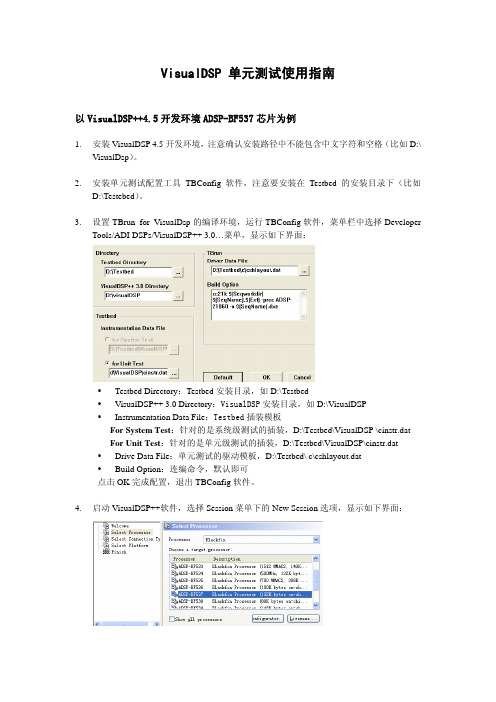
2.安装单元测试配置工具TBConfig软件,注意要安装在Testbed的安装目录下(比如D:\Testebed)。
3.设置TBrun for VisualDsp的编译环境,运行TBConfig软件,菜单栏中选择DeveloperTools/ADI DSPs/VisualDSP++ 3.0…菜单,显示如下界面:y Testbed Directory:Testbed安装目录,如D:\Testbedy VisualDSP++ 3.0 Directory:VisualDSP安装目录,如D:\VisualDSPy Instrumentation Data File:Testbed插装模板For System Test:针对的是系统级测试的插装,D:\Testbed\VisualDSP \cinstr.datFor Unit Test:针对的是单元级测试的插装,D:\Testbed\VisualDSP\cinstr.dat y Drive Data File:单元测试的驱动模板,D:\Testbed\ c\cshlayout.daty Build Option:连编命令,默认即可点击OK完成配置,退出TBConfig软件。
4.启动VisualDSP++软件,选择Session菜单下的New Session选项,显示如下界面:在target processor中选择ADSP-BF537,设置当前的目标机为ADSP-BF537 ADSP-BF5xx Single Processor Simulator。
5.进入Setting菜单下Preference选项中的Project属性页面中,将 Reload last…的选项去掉,否则VisualDsp开发环境启动后会自动加载上次载入的项目,如下图所示:6.为了在命令行模式下直接调用VisualDsp开发环境的编译、链接以及执行命令,需要修改系统环境变量PATH(我的电脑/属性/高级/环境变量/系统环境变量),在路径头部添加“D:\VisualDSP\System;D:\VisualDSP;”,如下图所示:7.使用编辑工具打开插桩模板D:\Testbed\C\CINSTR.dat文件,若用户当前版本的插装模板中没有下面的内容(Testbed 7.4.0版本以后都存在,TBConfig工具会自动进行设置)则要在UNIX编辑模式下打开插装模版,放开/* #define QQFLUSH */的预编译宏目的是为了缓冲驱动程序的输出数据,最终产生历史记录文件。
云祺容灾备份系统安装指导手册说明书

云祺容灾备份系统安装指导手册关于云祺成都云祺科技有限公司(以下简称云祺科技)是国内专业的数据中心容灾备份解决方案提供商,也是国内首家专业的虚拟化备份解决方案提供商,致力于为全球用户提供高效的云环境及传统环境下的数据备份、恢复、容灾等整体解决方案。
云祺科技总部与研发基地位于成都国家西部信息安全产业园,公司为国家高新技术企业、瞪羚企业、专精特新企业,具备工信部ITSS 云服务能力三级认证。
云祺容灾备份系统是由云祺科技完全独立自主研发的云环境和传统环境下的数据保护产品,操作简单,安全可靠,满足多种场景下的备份需求。
为用户提供在私有云、公有云、混合云环境下的虚拟机、操作系统、数据库、文件定时备份与恢复、提供文件系统、卷、数据库等数据与应用的实时复制功能,异地副本等功能。
版权所有版权所有©2015—2023成都云祺科技有限公司,保留所有权利。
未经本公司许可,任何单位和个人不得以任何理由、任何形式复制、传播本文档的部分或全部内容,如有违反,本公司保留追究其法律责任的权利。
使用声明本文档仅提供阶段性信息,由于产品版本升级或其它原因,所含内容根据产品的实际情况随时更新,恕不另行通知。
如因文档使用不当造成的直接或间接损失,本公司不承担任何责任。
前言文档说明感谢您选用云祺容灾备份系统产品,本文档主要介绍云祺容灾备份系统产品安装部署指导,在您安装部署使用云祺容灾备份系统产品前,请详细阅读本文档。
适用对象本文档建议适用于以下对象:⚫售前工程师⚫技术工程师⚫实施工程师适用产品本手册适合云祺容灾备份系统下列版本安装部署符号说明在本文中可能出现下列标志,它们所代表的含义如下。
目录1. 安装部署说明 (1)2. 安装配置要求 (2)3. 安装介质准备 (4)4. 备份系统部署 (8)4.1.1. 安装引导 (8)4.1.2. 安装配置 (9)4.1.3. 登录界面 (13)4.1.4. 系统配置 (14)云祺容灾备份系统可以安装部署到物理服务器,也可以安装部署到虚拟化平台的虚拟机中。
