变频器 毕业论文外文翻译
变频器外文翻译文献
变频器外文翻译文献(文档含中英文对照即英文原文和中文翻译)外文:Converter reference design(1)Converter Selection:Selection to determine the frequency converter when the following points:1) The purpose of a variable frequency; constant pressure to control or constant current control.2) the load converter types such as leaves or pump volume pumps, with special attention to load the performance curve, the performance curve of the decision of the ways and means.3) the frequency converter and load matchingVoltage match: a rated voltage converter with a rated voltage line with the load. Current matches: ordinary pump, the rated current inverter and motor rated current match. For special load such as deep-water pumps, and so on need to refer to the electrical performance parameters to determine the most current inverter current and Guozainengli.Torque match: in this case constant torque load or slow down when the device may have occurred.4) the use of high-speed motor drive inverter, because of the high-speed motor, anti-small, high harmonics lead to increased output current value increases. So for high-speed motor inverter Selection, its capacity to be slightly larger than the ordinary motor selection.5) If the frequency converter to a long cable run, this time to take measures to curb the long cable to the impact of capacitive coupling, inadequate efforts to avoid converter, so in this case, the drive to enlarge the capacity of a file or the converter Output installed output reactor.6) For the application of some special occasions, such as high temperatures, high altitude, at this time would cause the down converter capacity, the drive to enlarge the capacity of a block.(2) inverter control schematic design:1) First confirmation of the installation environment ConverterOperating temperature: high-power converter is the internal electronic components, vulnerable to the effects of temperature, product general requirementsfor 0 ~ 55 ℃, but in order to ensure the safe, reliable, the use of room to be taken into account, the best control in 40 ℃below. In the control box, the converter box should generally be installed in the upper and strictly comply with the Manual of installation requirements, absolutely not be allowed to heating elements or components easily fever close to the converter installed at the bottom.Ambient temperature: the temperature is too high and large temperature changes, within easy converter there is dew, the insulation properties will be greatly reduced,or even short-circuit caused the accident. When necessary, to be added to the desiccant in the box and heater. In water treatment, generally heavier than water vapor, if the temperature changes, then this problem would be more prominent.Corrosive gases: the use of the environment if the corrosive gas concentrations, will not only lead corrosion of components, printed circuit boards, but it will also accelerate the aging of plastic devices, reducing insulation properties.Vibration and shock: the control cabinet with converter by vibration and mechanical shocks will cause electrical connection is bad. Huaian thermoelectric there such a problem. Apart from raising the control cabinet at this time of the mechanical strength, vibration and shock away from the source, we must also use seismic rubber pad fixed within and outside the control cabinet, such as electromagnetic switches have a vibration components. Equipment operation after a period of time and should conduct inspections and maintenance.Electromagnetic interference: Inverter at work due to rectification and frequency, produce around a lot of electromagnetic interference, these high-frequency electromagnetic waves in the vicinity of the instrument, apparatus, a certain interference. Therefore, the cabinet instrumentation and electronic systems, it should be optional metal, shielding the inverter instrument interference. All the components should be reliable grounding, in addition, the electrical components, equipment andinstrumentation should use the connectivity between the shielding control cables, and the shield should be grounded. If handled properly electromagnetic interference, often cause the entire system does not work, leading to the control unit failure or damage.2) Drives and determine the distance between the electrical cables and wiring methodsDrives and motor the short distance should be as much as possible. This reduces the capacitance of the cable, reducing the emission source of interference.Control cables optional shielded cable, power cable or optional shielding from the cable converter to use all the threads of the electrical shield.Electric cables should be independent of the other cable alignment, the minimum distance of 500 mm. At the same time should avoid the electrical cables and other long-running cable lines, in order to reduce the output voltage inverter rapid changes in the electromagnetic interference. If the control cables and power cables cross, as far as possible so that they cross the 90-degree angle. Converter and analog signals on the line and back to the main line of separation of alignment, even in the case also in the control cabinet.And the analog signal converter line the best choice of unshielded twisted pair, shielded power cables selection of the three-core cable (its specifications than ordinary electrical cables in the files) or to comply with the user manual converter.3) inverter control schematicsMain circuit: the role of reactor is to prevent the high-frequency converter harmonic power through the input circuit to return to the grid by the impact of other electronic devices, in accordance with the capacity size converter to decide whether to increase reactor; filter Converter is installed in the output, the output of high-frequency converter to reduce harmonics, when the electrical inverter to the longer distance, we should install filters. Although the frequency converter itself has all kinds of protection, but the lack of protection is not perfect, the main circuit breaker played overload, lack the same protection, selection, in accordance with the capacity to choose the frequency converter. Converter itself can be used to replace thermal overload protection relay.Control loop: the frequency with the frequency manually switch to the failure frequency can be manually cut-operation, not because of output voltage, frequency and frequency-be interlocked.4) Inverter groundingInverter correct grounding is to improve the system stability, the ability to inhibit an important means of noise. Inverter grounding resistance grounding terminal of the smaller the better, the grounding wire cross-section of not less than 4 mm, the length of not more than 5 m. Inverter should be grounded and power equipment to the sites separately, not in total. The shield signal converter from one end of the grounding end, the other floating air. Inverter and control of electrical between the same counter.(3) Inverter Control DesignConverter should be installed in the control cabinet internal control counters in the design should pay attention to the following issues1) heat: Inverter fever is the internal loss. In the frequency converter in the main part of the loss mainly to the main circuit, or about 98 percent, accounting for 2% of control circuits. In order to ensure reliable operation of the normal inverter, Thermal must inverter are usually used for cooling fan; converter fan of the contents of the converter box can be removed internal heat, if the fan does not work, should immediately stop inverter Operation; the high-power inverter also need to increase control Guishang fan, Control of the wind, to design a reasonable, all outlet into the net to set up dust, exhaust open, to avoid over the counter in a swirl, in a fixed location dust Accumulation, according to the statement converter ventilation fans to select the match, fans installed to the attention of earthquake problems.2) the problem of electromagnetic interferenceConverter in its work due to rectification and frequency, produce around a lot of electromagnetic interference, these high-frequency electromagnetic waves in the vicinity of the instrument, apparatus, a certain interference, and will produce high harmonics, the high harmonics will be available for adoption Xinhua loop into the whole power supply network, thus affecting other instruments. If the power inverter system as a whole lot of more than 25 percent, to be considered the anti-jammingmeasures to control supply.When the system in the high-frequency welding machine such as the impact load, electroplating power, the converter itself will appear as interference protection, to consider the whole system of power quality problems.3) protection issues need to pay attention to the following pointsWaterproof anti-condensation: If the converter on the scene, the need to pay attention to the frequency converter Guishang not have the flange or other pipeline leak, the inverter can not be near the water splash, sum up the scene OEM Switchgear Kits & level of security to IP43 above.BOOT: All outlet into the net to set up dust debris into the barrier floc, dust network should be designed to be removable, to facilitate the clean-up, maintenance. Dust of the grid network in accordance with the specific circumstances at the scene determined that dust around the net and Control Department to handle the combination of tight.Anti-corrosive gases: the chemical industry in this relatively Most of this can be on the frequency counters in the control room.(4) converter cable normsSignal lines and power lines must be separately alignment: the use of analog signal converter for remote control, in order to reduce the analog converter and other equipment from the interference, please control signal converter line with the strong electric circuit (H Circuit-and-loop) separate alignment. Distance should be 30 cm above. Even in the control cabinet, the same connection to maintain such a standard. The signal converter and the control should not be longer than the road back to 50 m. Signal lines and power lines must be placed in different metal pipe or metal hose internal: connect PLC and the signal converter if not placed in metal tubes, Drives and vulnerable to external interference equipment; because the converter No built-in the reactor, so the converter input and output level of external power line will have a very strong interference, placing the signal lines of metal or metal hose has to be extended to the inverter control terminal, to ensure that the signal Line and the complete separation of power lines.1) analog control signal line should use two-strands shielding line, cable specifications for 0.75 mm2. When the wiring must pay attention to, to the extent possible, the cable Baoxian short (5-7 mm or so), while Bao Xian after the shield should wrap insulating tape to prevent shielding lines and other equipment contact with the introduction of interference.2) To improve the simple wiring and reliability, signal recommend the use of online video pressure bar.(5) converter and the operation of the relevant parameters setInverter setting parameters, the parameters of each have a certain range of options, often encountered in the use of individual set of parameters for misconduct, leading converter does not work phenomenon.Control: that is, speed control, transferred from the control, PID control or other means. To take control, according to the general control precision, the need for static or dynamic identification.Running a minimum of: that is, the minimum speed motor running, the motor running at low speed, its poor performance cooling, electrical long run on low speed, it can cause burning motor. And at low speed, the cable will increase in the current, cable will lead to fever.The maximum operating frequency: the general maximum frequency converter to 60 Hz, and some even to 400 Hz, high-frequency will enable high-speed motor operation, which the ordinary motor, its bearings can not be over-speed long run, whether the motor rotor To be capable of such a centrifugal force.Carrier frequency: the higher the carrier frequency setting its high harmonics greater weight, and the length of cable, the electrical heating, cable converter fever fever and other factors are closely related.Electrical parameters: the frequency converter to set parameters of the motor power, current, voltage, speed, maximum frequency, these parameters can be directly in the motor nameplate.FH: In a frequency point, there may be a resonance phenomenon, particularly in the relatively high when the entire device in control of the compressor, thecompressor to avoid the surge point.(6) common fault analysis1) flow failure: over-current fault can be divided into acceleration, deceleration, constant speed over-current. May be due to the increase in frequency converter too little time to slow down, load mutations, the unequal distribution of load, output short-circuit, and other causes. At this time can be extended by the general acceleration and deceleration time, reduce the load of mutations, plus braking energy components, load distribution design, the lines to be checked. If off-load converter ora failure that has been Central converter inverter circuits, to be replaced converter.2) overload fault: overload fault, including frequency and overload the electrical overload. May be accelerated their time is too short, too low voltage power grids, Fuzaiguochong and other causes. General can be accelerated through the extension of time to extend the braking time, such as check-voltage power grid. Fuzaiguochong, selected motor and inverter can not drag the load, but also may be due to poor machinery lubrication caused. If the former is the need to replace high-power motors and inverter, if the latter will have to carry out maintenance on production machinery.3) under-voltage: the importation of some of the power inverter that there are problems, need to check before you can run.变频器设计使用参考(1)变频器选型:变频器选型时要确定以下几点:1) 采用变频的目的;恒压控制或恒流控制等。
变频器工作原理外文文献翻译、中英文翻译
变频器工作原理外文文献翻译、中英文翻译外文资料Converter working principleMain circuit is for induction motors provide voltage variable frequency power source power conversion part, the inverter main circuit in general can be divided into two categories [1]: voltage is voltage source DC converter for AC inverter, the DC loop filter is capacitance. Current model is the current source of the direct streamization AC inverter, the DC circuit filter inductance. It consists of three parts, the power supply conversion for DC power rectifier, absorption produced in converter and inverter voltage ripple "flat wave circuit, and DC power converter for AC power" inverter ".(1) rectifier: Recently a lot of use is diode converter, it is the power supply conversion for the DC power supply. Also available two groups of transistor converters constitute a reversible converter, due to its power direction reversible can regeneration operation.(2) the flat wave circuit: in the rectifier DC voltage, containing 6 times the frequency of power supply ripple voltage, furthermore the inverter produces a pulsating current the DC voltage changes. In order to suppress the voltage fluctuation, the inductance and capacitance absorption pulsating voltage (current). Device volume hours, if power supply and a main circuit component in margin can save inductance of the simple flat wave circuit.(3) inverter: Contrary to rectifier, inverter is the DC power conversion is the desired frequency AC power and to determine the time the six switch device turn-on and off you can get 3 phaseAC output. By voltage type PWM converter as exemplifying the switching time and voltage waveform.Control circuit is to provide a loop control signal to the asynchronous motor power supply (voltage, frequency) of the main circuit, the frequency, the voltage "operation circuit", the main circuit of the "voltage and current detection circuit, the motor" speed detection circuit, operation circuit of control signal amplification drive circuit ", and the inverter and the motor" protection circuit.(1) arithmetic circuit: the external speed, torque and other instructions with the detection circuit of the current, voltage signal comparison operation, determine the output voltage of the inverter, frequency.(2) voltage, current detection circuit: with the main circuit potential isolation detection voltage, current and so on.(3) driving circuit, driving circuit of main circuit devices. It and control isolation circuit enable device in the main circuit turn-on, turn off.(4) speed detection circuit installed in asynchronous motor shaft machine speed detector (TG, PLG) signal for speed signal into the computing circuit, according to the instruction and operation can make the motor run in the speed command.(5) protection circuit: detection of the main circuit of the voltage, current and so on, when the occurrence of overload or over voltage, etc., in order to prevent the inverter and asynchronous motor damage, so that the inverter to stop working or inhibit voltage, current value.中文翻译变频器工作原理主电路是给异步电动机提供调压调频电源的电力变换部分,变频器的主电路大体上可分为两类[1]:电压型是将电压源的直流变换为交流的变频器,直流回路的滤波是电容。
变频器-PLC在供水控制系统的应用中英文对照翻译全文

Transducer in the water control system applicationsCurrently,the water level control in a large part of the electrical pumps are not towing gear shift system, no gear shift most of the electrical energy consumed in the water supply to the frequent changes in the pumps stopped. This not only makes the electrical work in inefficient zones, cut short the useful life of electrical and electrical equipment for the frequent failure to stop the high rate, leading to serious waste of water resources, system maintenance,repairs larger workload。
With high living water and industrial water gradually increased, the traditional control methods that are outdated。
Originally used for artificial water level control,water level due to the lack of accurate positioning hour monitoring,it is difficult to accurately control the pumps have stopped;Using buoys or mechanical control devices such as water supply situation has made some changes,but because of mechanical failure more devices,poor reliability to maintenance will face great trouble。
PLC及变频器技术论文中英文资料对照外文翻译文献综述

PLC及变频器技术中英文资料对照外文翻译文献综述PLC and inverter technology trends1. The development trend of the programmable controller“PLC is one kind specially for the digital operation operation electronic installation which applies under the industry environment designs. It uses may the coding memory, uses for in its internal memory operation and so on actuating logic operation, sequence operation, time, counting and arithmetic operation instructions, and can through digital or the simulation-like input and the output, controls each type the machinery or the production process. PLC and the related auxiliary equipment should according to form a whole easy with the industrial control system, easy to expand its function the principle to design.”In the 21st century, PLC will have a bigger development. Technologically speaking, computer technology's new achievement more will apply in the programmable controller's design and the manufacture, will have the operating speed to be quicker, the storage capacity to be bigger, an intelligent stronger variety to appear; Looked from the product scale that further develops to subminiature and the ultra-large direction; Looked from the product overcoatability that the product variety will be richer, the specification to be more complete, the perfect man-machine contact surface, the complete communication facility will adapt each industrial control situation demand well; Looked from the market that various countries will produce the multi-variety product the situation to break respectively along with the international competition aggravating, will present the minority several brand monopoly international market the aspect, will present the international general programming language; Looking from the network state of play, the programmable controller and other industrial control computer networkconstitution large-scale control system is the programmable controller technology development direction. Present computer collection and distribution control system DCS (Distributed Control System) had the massive programmable controller application. Is following computer network's development, the programmable controller takes the automation directed net and the international universal network important component, outside industry and industry numerous domain display more and more major function.2. Inverter technology development trendsInverter into the practical phase of more than 1 / 4 century during this period, the frequency converter technology as the basis of power electronics technology and microelectronics technology manager of a leap in the development, as the new power electronic devices and high-performance microprocessor The application of control technology and the development of increasingly high cost performance of the inverter, more and more small size, but manufacturers are still in constant frequency converter to achieve the further miniaturization and doing new efforts. From a technical point of view, with the frequency converter to further expand the market of the future, with the converter and inverter technology will be on the development of technologies in the following areas further development:(1) large capacity and small size;(2) high-performance and multi-function;(3) enhance the ease-of-use;(4) increase in life expectancy and reliability;(5) of pollution-free.Large capacity and small size of the power semiconductor devices will be with the development of continuous development. In recent years, driven by a voltage power semiconductor devices IGBT (Isolated Gate Bipolar Transistor, isolation gate bipolar transistors) has developed very rapidly and quickly into the traditional use of BJT (bipolar power transistor) and power MOSFET (FET) The various fields. In addition, the IGBT switching device for the IPM (Intelligent Power Module, IPM) and Monolithic Power IC chip will power switching devices and driving circuit, such as the protection of integrated circuits in the same package, with high performance andreliability The merits, with their high current and high pressure of the development of small and medium-sized converter will certainly be more widely used.With micro-electronics technology and semiconductor technology development, for Inverter CPU and semiconductor devices and a variety of sensors of getting higher and higher. With the frequency converter technology and the development of the growing maturity of the exchange governor, modern control theory are constantly new applications. These have further improved the performance of inverter provided the conditions. In addition, with the frequency converter to further promote the use and support are also constantly made new demands, the frequency converter manufacturers to continuously improve the performance and frequency converter functions in Inverter new efforts to meet user And the need for the fierce competition in the market in an invincible position.With the frequency converter market continues to expand, how to further enhance the ease-of-use inverter, so that the technical staff and even ordinary non-technical staff can quickly master the use of frequency converter technology has become manufacturers must consider the issue. Because only easy-to-use products can continue to acquire new customers and further expand the market, so the future of the new converter will be more easy to operate.With the development of semiconductor technology and the development of power electronics technology, the frequency converter used in the various components of the life and reliability are constantly improving, they will make their own life and the frequency converter to further increase reliability.In recent years, people have attached great importance to environmental issues, and thus a "green products" name. Therefore, the inverter, must also consider its impact on the surrounding environment.Promote the use of the frequency converter in the early stages of the noise problem was once a big problem. With the low-noise converter IGBT the emergence of this issue has basically been resolved. However, with the noise problem to solve, people's looks and a converter to the surrounding environment and the impact of other continuously explore new solutions. For example, the use of a diode-voltage converter and PWMinverter circuit converter, the frequency converter itself the high harmonics will bring supply voltage and current distortion, and at the same power to affect the other equipment. However, through the use of the frequency converter Rectifier circuit PWM, we can basically solve the problem. Although because of price and control technology and other aspects of the reasons for the current PWM converter has not been promoting the inverter, but, with the frequency converter technology development and the people of the importance of environmental issues.PLC及变频器技术的发展趋势1.可编程控制器的发展趋势可编程控制器是一种数字运算操作的电子系统,专为在工业环境下应用而设计。
变频器外文翻译文献
变频器外文翻译文献(文档含中英文对照即英文原文和中文翻译)外文:Converter reference design(1)Converter Selection:Selection to determine the frequency converter when the following points:1) The purpose of a variable frequency; constant pressure to control or constant current control.2) the load converter types such as leaves or pump volume pumps, with special attention to load the performance curve, the performance curve of the decision of the ways and means.3) the frequency converter and load matchingVoltage match: a rated voltage converter with a rated voltage line with the load. Current matches: ordinary pump, the rated current inverter and motor rated current match. For special load such as deep-water pumps, and so on need to refer to the electrical performance parameters to determine the most current inverter current and Guozainengli.Torque match: in this case constant torque load or slow down when the device may have occurred.4) the use of high-speed motor drive inverter, because of the high-speed motor, anti-small, high harmonics lead to increased output current value increases. So for high-speed motor inverter Selection, its capacity to be slightly larger than the ordinary motor selection.5) If the frequency converter to a long cable run, this time to take measures to curb the long cable to the impact of capacitive coupling, inadequate efforts to avoid converter, so in this case, the drive to enlarge the capacity of a file or the converter Output installed output reactor.6) For the application of some special occasions, such as high temperatures, high altitude, at this time would cause the down converter capacity, the drive to enlarge the capacity of a block.(2) inverter control schematic design:1) First confirmation of the installation environment ConverterOperating temperature: high-power converter is the internal electronic components, vulnerable to the effects of temperature, product general requirementsfor 0 ~ 55 ℃, but in order to ensure the safe, reliable, the use of room to be taken into account, the best control in 40 ℃below. In the control box, the converter box should generally be installed in the upper and strictly comply with the Manual of installation requirements, absolutely not be allowed to heating elements or components easily fever close to the converter installed at the bottom.Ambient temperature: the temperature is too high and large temperature changes, within easy converter there is dew, the insulation properties will be greatly reduced,or even short-circuit caused the accident. When necessary, to be added to the desiccant in the box and heater. In water treatment, generally heavier than water vapor, if the temperature changes, then this problem would be more prominent.Corrosive gases: the use of the environment if the corrosive gas concentrations, will not only lead corrosion of components, printed circuit boards, but it will also accelerate the aging of plastic devices, reducing insulation properties.Vibration and shock: the control cabinet with converter by vibration and mechanical shocks will cause electrical connection is bad. Huaian thermoelectric there such a problem. Apart from raising the control cabinet at this time of the mechanical strength, vibration and shock away from the source, we must also use seismic rubber pad fixed within and outside the control cabinet, such as electromagnetic switches have a vibration components. Equipment operation after a period of time and should conduct inspections and maintenance.Electromagnetic interference: Inverter at work due to rectification and frequency, produce around a lot of electromagnetic interference, these high-frequency electromagnetic waves in the vicinity of the instrument, apparatus, a certain interference. Therefore, the cabinet instrumentation and electronic systems, it should be optional metal, shielding the inverter instrument interference. All the components should be reliable grounding, in addition, the electrical components, equipment andinstrumentation should use the connectivity between the shielding control cables, and the shield should be grounded. If handled properly electromagnetic interference, often cause the entire system does not work, leading to the control unit failure or damage.2) Drives and determine the distance between the electrical cables and wiring methodsDrives and motor the short distance should be as much as possible. This reduces the capacitance of the cable, reducing the emission source of interference.Control cables optional shielded cable, power cable or optional shielding from the cable converter to use all the threads of the electrical shield.Electric cables should be independent of the other cable alignment, the minimum distance of 500 mm. At the same time should avoid the electrical cables and other long-running cable lines, in order to reduce the output voltage inverter rapid changes in the electromagnetic interference. If the control cables and power cables cross, as far as possible so that they cross the 90-degree angle. Converter and analog signals on the line and back to the main line of separation of alignment, even in the case also in the control cabinet.And the analog signal converter line the best choice of unshielded twisted pair, shielded power cables selection of the three-core cable (its specifications than ordinary electrical cables in the files) or to comply with the user manual converter.3) inverter control schematicsMain circuit: the role of reactor is to prevent the high-frequency converter harmonic power through the input circuit to return to the grid by the impact of other electronic devices, in accordance with the capacity size converter to decide whether to increase reactor; filter Converter is installed in the output, the output of high-frequency converter to reduce harmonics, when the electrical inverter to the longer distance, we should install filters. Although the frequency converter itself has all kinds of protection, but the lack of protection is not perfect, the main circuit breaker played overload, lack the same protection, selection, in accordance with the capacity to choose the frequency converter. Converter itself can be used to replace thermal overload protection relay.Control loop: the frequency with the frequency manually switch to the failure frequency can be manually cut-operation, not because of output voltage, frequency and frequency-be interlocked.4) Inverter groundingInverter correct grounding is to improve the system stability, the ability to inhibit an important means of noise. Inverter grounding resistance grounding terminal of the smaller the better, the grounding wire cross-section of not less than 4 mm, the length of not more than 5 m. Inverter should be grounded and power equipment to the sites separately, not in total. The shield signal converter from one end of the grounding end, the other floating air. Inverter and control of electrical between the same counter.(3) Inverter Control DesignConverter should be installed in the control cabinet internal control counters in the design should pay attention to the following issues1) heat: Inverter fever is the internal loss. In the frequency converter in the main part of the loss mainly to the main circuit, or about 98 percent, accounting for 2% of control circuits. In order to ensure reliable operation of the normal inverter, Thermal must inverter are usually used for cooling fan; converter fan of the contents of the converter box can be removed internal heat, if the fan does not work, should immediately stop inverter Operation; the high-power inverter also need to increase control Guishang fan, Control of the wind, to design a reasonable, all outlet into the net to set up dust, exhaust open, to avoid over the counter in a swirl, in a fixed location dust Accumulation, according to the statement converter ventilation fans to select the match, fans installed to the attention of earthquake problems.2) the problem of electromagnetic interferenceConverter in its work due to rectification and frequency, produce around a lot of electromagnetic interference, these high-frequency electromagnetic waves in the vicinity of the instrument, apparatus, a certain interference, and will produce high harmonics, the high harmonics will be available for adoption Xinhua loop into the whole power supply network, thus affecting other instruments. If the power inverter system as a whole lot of more than 25 percent, to be considered the anti-jammingmeasures to control supply.When the system in the high-frequency welding machine such as the impact load, electroplating power, the converter itself will appear as interference protection, to consider the whole system of power quality problems.3) protection issues need to pay attention to the following pointsWaterproof anti-condensation: If the converter on the scene, the need to pay attention to the frequency converter Guishang not have the flange or other pipeline leak, the inverter can not be near the water splash, sum up the scene OEM Switchgear Kits & level of security to IP43 above.BOOT: All outlet into the net to set up dust debris into the barrier floc, dust network should be designed to be removable, to facilitate the clean-up, maintenance. Dust of the grid network in accordance with the specific circumstances at the scene determined that dust around the net and Control Department to handle the combination of tight.Anti-corrosive gases: the chemical industry in this relatively Most of this can be on the frequency counters in the control room.(4) converter cable normsSignal lines and power lines must be separately alignment: the use of analog signal converter for remote control, in order to reduce the analog converter and other equipment from the interference, please control signal converter line with the strong electric circuit (H Circuit-and-loop) separate alignment. Distance should be 30 cm above. Even in the control cabinet, the same connection to maintain such a standard. The signal converter and the control should not be longer than the road back to 50 m. Signal lines and power lines must be placed in different metal pipe or metal hose internal: connect PLC and the signal converter if not placed in metal tubes, Drives and vulnerable to external interference equipment; because the converter No built-in the reactor, so the converter input and output level of external power line will have a very strong interference, placing the signal lines of metal or metal hose has to be extended to the inverter control terminal, to ensure that the signal Line and the complete separation of power lines.1) analog control signal line should use two-strands shielding line, cable specifications for 0.75 mm2. When the wiring must pay attention to, to the extent possible, the cable Baoxian short (5-7 mm or so), while Bao Xian after the shield should wrap insulating tape to prevent shielding lines and other equipment contact with the introduction of interference.2) To improve the simple wiring and reliability, signal recommend the use of online video pressure bar.(5) converter and the operation of the relevant parameters setInverter setting parameters, the parameters of each have a certain range of options, often encountered in the use of individual set of parameters for misconduct, leading converter does not work phenomenon.Control: that is, speed control, transferred from the control, PID control or other means. To take control, according to the general control precision, the need for static or dynamic identification.Running a minimum of: that is, the minimum speed motor running, the motor running at low speed, its poor performance cooling, electrical long run on low speed, it can cause burning motor. And at low speed, the cable will increase in the current, cable will lead to fever.The maximum operating frequency: the general maximum frequency converter to 60 Hz, and some even to 400 Hz, high-frequency will enable high-speed motor operation, which the ordinary motor, its bearings can not be over-speed long run, whether the motor rotor To be capable of such a centrifugal force.Carrier frequency: the higher the carrier frequency setting its high harmonics greater weight, and the length of cable, the electrical heating, cable converter fever fever and other factors are closely related.Electrical parameters: the frequency converter to set parameters of the motor power, current, voltage, speed, maximum frequency, these parameters can be directly in the motor nameplate.FH: In a frequency point, there may be a resonance phenomenon, particularly in the relatively high when the entire device in control of the compressor, thecompressor to avoid the surge point.(6) common fault analysis1) flow failure: over-current fault can be divided into acceleration, deceleration, constant speed over-current. May be due to the increase in frequency converter too little time to slow down, load mutations, the unequal distribution of load, output short-circuit, and other causes. At this time can be extended by the general acceleration and deceleration time, reduce the load of mutations, plus braking energy components, load distribution design, the lines to be checked. If off-load converter ora failure that has been Central converter inverter circuits, to be replaced converter.2) overload fault: overload fault, including frequency and overload the electrical overload. May be accelerated their time is too short, too low voltage power grids, Fuzaiguochong and other causes. General can be accelerated through the extension of time to extend the braking time, such as check-voltage power grid. Fuzaiguochong, selected motor and inverter can not drag the load, but also may be due to poor machinery lubrication caused. If the former is the need to replace high-power motors and inverter, if the latter will have to carry out maintenance on production machinery.3) under-voltage: the importation of some of the power inverter that there are problems, need to check before you can run.变频器设计使用参考(1)变频器选型:变频器选型时要确定以下几点:1) 采用变频的目的;恒压控制或恒流控制等。
三相,电能质量改进的直交变频器外文翻译
毕业设计(论文)外文资料翻译学院:专业:姓名:学号:外文出处:Electric Power Systems Research78(2008)276-289附件: 1.外文资料翻译译文;2.外文原文。
指导教师评语:签名:年月日附件1:外文资料翻译译文三相,电能质量改进的直/交变频器概要除了谐波功率和无功功率的其他来源,电力电子变频器的广泛使用大大影响着谐波的产生和在电力系统的无功潮流。
单相,电能质量改进的变频器在国内设计,开发和成功应用,商业和工业环境已经使三相,电能改进的变频器的设计和发展成为可能,而且它们广泛使用在不同的应用。
本文将对三相,电能改进的变频器配置,控制方法,对供应方和负载性能的输入功率因数计算,总谐波失真和完善管理,缩减波纹直流输出,额定功率,成本和特定应用选择做全面的探讨。
它还提供了国家在电能质量改善的变频器对工作在三相,开关式交直交变频器的研究人员,设计师和工程师而言最先进的技术。
内容1 说明交直交电源变频器广泛应用于各种应用,如电源供应器、直流马达驱动,调速交流驱动器、直流输出、开关电源前端变频器、实用接口与非传统能源来源。
在工艺技术,如焊接、电信系统的电源供应器、航空航天、军事环境等。
传统上,交直交电源变频器已主要由二极管或作为对电力系统非线性负载和在谐波的丰富,供应不足的功率因数的相控整流器作为借鉴,然而出现了配电网络和附近其他电器的整流系统的电能质量问题。
其他与这些变频器相关的问题包括:(1)从要求配电设备的处理大功率的电力系统大量无功功率由整流器得出,从而增加其伏安评级。
(2)电压在总线下降。
(3)较高的输入电流谐波导致扭曲的线电流,往往扭曲线电压波形。
这往往造成在同一总线上的敏感设备可靠运行的问题。
(4)在设备中增加损失(由于谐波)如变压器和电机连接到实际应用。
(5)与附近的通信线路电磁干扰。
(6)由于来自共振的高电压和电流与线路阻抗和电容故障,保险丝对电容器功率因数校正。
毕业设计外文翻译:在频率变运行过程中存在的疑问和对策
In the frequency changer movement process existsquestion and countermeasureThis paper analyzed the problem of harmonic wave, matching of load andcalorification for inverters in running, and made the relatively the measure.Keywords: inverter harmonic wave loading calorification1 forewordhas entered the Chinese market since the 80's general frequency changers, obtained the extremely widespread application in the short several year time.At present, the general frequency changer by its merits and so on intellectualization, digitization, network more and more receives people's favor.Along with the general frequency changer application scope expansion, the question which exposes more and more are also many, mainly has following several aspects:① Overtone question ② Frequency changer matching of load question ③ Gave off heat abovethe question these questions already to cause the related control section and the factory and mine attention and has formulated the related technical standard.If the overto ne question, our country and in 1993 passed “the electrical power system overtone management temporary provisions” in 1984 and the GB/T-14549-93 standard, with limits the power supply system and the current collector overtone pollution. In view of the above question, this article carried on has analyzed and proposed the solution and the countermeasure.2 overtone questions and the countermeasuregeneral frequency changer main circuit form is composed generally by three parts: Rectification part, contravariant part and filter part.The rectification part for the three-phase bridge type uncontrolled rectifier, the invertor part is the IGBT three-phase bridge type invertor, also the output is the PWM profile.Regarding the bipolarity modulation frequencychanger.because the general frequency changer rectification part uses the diode uncontrolled bridge type leveling circuit, the middle filter part uses the big electric capacity to take the filter, therefore the rectifier input current in fact is the capacitor charging current, assumes a higher more and precipitous pulse wave, its harmonic component is big.For the harmonic cancellation, may use following countermeasure:①Increase frequency changer electric power supply internal resistance In the usual situation, the power equipment internal resistance may play the cushion frequency changer cocurrent filter electric capacity reactive power role.This kind of internal resistance is the transformer short-circuit impedance.When power source capacity relative frequency changer capacity hour, then internal resistance value relative bigger, the harmonic content is smaller; When the power source capacity relative frequency changer capacity is bigger, then internal resistance value relative bigger, the harmonic content is bigger. Regarding Mitsubishi FR-F540 series frequency changer, when internal resistance is 4%, may play the very good harmonic suppression role .Therefore time choice frequency changer electric power supply transformer, best choice short-circuit impedance big transformer.(2) Installs the reactor to install the reactor in fact from exterior increase frequency changer electric power supply internal resistance. Installs the direct current reactor in the frequency changer exchange side installment exchange reactor or in the frequency changer direct current side, or also installs, suppression harmonic current. The table as soon as listed the Mitsubishi FR-A540 frequency changer to install the reactor and not to install the reactor the content comparative table.(3) The transformer heterogeneity movement general frequency changer rectification part is six pulse waves rectifiers, therefore produces the overtone is bigger. If applies the transformer the heterogeneity movement, causes mutually to miss 30° like Y- △, △ - △ the combination two transformers constitution is equal to 12 pulse waves effects may reduce the harmonic current 28%, played the very good harmonic suppression role.(4) Adjusts the frequency changer the carrier compared to from (1), (2), (3) the formula may see, so long as the carrier enough is bigger than, comparatively 低次the overtone may effectively suppress, specially the reference wave peak-to-peak value and the carrier peak-to-peak value are smaller than 1 o'clock, 13 below odd number overtone no longer appears.(5) Special-purpose filter this special-purpose filter uses in to examine the frequency changer harmonic current the peak-to-peak value and the phase, and produces to be same also the phase just right opposite electric current with the harmonic current peak-to-peak value, passes through in the frequency changer, thus may extremely effectively absorb the harmonic current.3 matchings of load question and its the countermeasure produce machinery the type to be many, performance and technological requirement respectivelydifferent,its torque characteristics is complex, roughly divides into three kind of types: The permanent torque loading, the air blower pump a kind of load and the permanent power load. In view of the different load type, should choose the different type the frequency changer.(1) The permanent torque loading permanent torque loading is refers to the load moment to have nothing to do with with the rotational speed, under any rotational speed, the torque maintains constantly. The permanent torque loading divides into the friction class load and the potential energy type load. About friction class load starting moment general request nominal torque 150%, about brake torque general request nominal torque 100%, therefore the frequency changer should choose these to have the constant torque characteristics, and starts and the brake torque all quite big, the overload time is long and the overload capacity big frequency changer. If Mitsubishi frequency changer FR-A540 series. The potential energy type load generally requests the big starting moment and the energy back coupling function, can fast realize is reversing, the frequency changer should choose has four quadrants running ability the frequency changer. If Mitsubishi frequency changer FR-A241 series. (2) air blower pumps the kind of load air blower to pump a kind of load is present industry field application mostequipment, although pumps the gentle breeze machine characteristic many and varied, but mainly by the centrifugal pump and the centrifugal air blower application primarily, the general frequency changer are most in this kind of load application. The air blower pumps a kind of load is one square torque loading, its rotational speed n and current capacity Q.May see from the previous type, the air blower load system rotation inertia computation is wants extremely again. When frequency changer concrete design, presses down the type computed result, carries on the suitable revision, starts when the frequency changer in the situation which does not have the class to trip decelerates with the frequency changer when does not occur 过电压 trips, choice shortest time.Pumps a kind of load in the actual movement process, is easy to have the buzz, the build the pressure and the water hangs the effect, therefore time frequency changer shaping, must choose is suitable for to pump a kind of load the frequency changer also the frequency changer when the function hypothesis must aim at the above question to carry on alone establishes:Buzz: Surveys easily to have the buzz frequency spot, jumps the frequency through the hypothesis and the width, avoids the phylogeny resonance effect. Build the pressure: Pumps a kind of load when the low speed movement, causes the current capacity as a result of the system build the pressure is zero, thus creates pumps burn outs. When frequency changer function hypothesis, through defines the frequency changer the most low frequency, but had defined pumps the current capacity the critical point place system lowest rotational speed, this has avoided this kind of phenomenon occurrence.The water hangs the effect: Pumps a kind of load when the sudden power failure, as a result of pumps in the pipeline the liquid gravity to flow backwards. If the check valve is lax or does not have the check valve, will cause the electrical machinery reverse, will cause the frequency changer because of the electrical machinery electricity generation to break down to report to the police burn outs. When frequency changer system design, should cause the frequency changer to stop according to the deceleration curve, separates the main circuit electricity again after electrical machinery dead stop, or thehypothesis "the power failure decelerates stops" the function, has like this avoided this phenomenon occurrence.(3) The permanent power loadpermanent power load is refers to the torque roughly with to transfer the intensive inverse ratio the load, like coiler, opening a book machine and so on. Actuates the permanent power load when using the frequency changer, should be, the usual consideration which speaking of the certain speed change scope below some rotational speed selects the permanent torque velocity modulation method, but when is higher than this rotational speed only then selects the permanent power velocity modulation method. We usually are called this rotational speed spot the base frequency, this point correspondence voltage for frequency changer output rated voltage.Theoretically speaking, must want to realize in the true significance permanent power control,Frequency changer output frequency f and output voltage U must follow the U2/f=const coordination control, but this is does not permit in the actual frequency changer movement process, because above the base frequency, the frequency changer output voltage cannot increase along with its output frequency, only can maintain the rated voltage,therefore only can be in one kind of approximate significance permanent power control.4 gives off heat the question and its the countermeasureFrequency changer giving off heat is produces by the internal loss. In the frequency changer in each part of losses mainly by the main circuit primarily, approximately composes 98%, the control circuit accounts for 2%. In order to guarantee the frequency changer normal reliable movement, must carry on the radiation to the frequency changer, usually uses following method:(1) Uses the ventilator radiation: The frequency changer internal installation ventilator may carry off the frequency changer box body interior radiation, if the ventilator cannot the normal work, be supposed to stop the frequency changer movement immediately.(2) Reduces installs the ambient temperature: Because the frequency changer is the electronic installation, content electron Yuan, electrolysiselectric capacity and so on, therefore the temperature quite is big to its life influence. The general frequency changer environment operating temperature generally requests -10 ℃ ~-50 ℃, if can take the measure to reduce the frequency changer operating temperature as far as possible, then the frequency changer service life lengthens, the performance quite is also stable.We adopt two methods: One method is the construction independent frequency changer low pressure, the interior installs the air conditioning, the maintenance low pressure the temperature in +15 ℃ ~+20 ℃ between. Another method is the frequency changer installment space needs to satisfy the frequency changer instruction for use the request.Above talks about the frequency changer gives off heat is refers to the frequency changer in the fixed scope the normal operation loss. When the frequency changer has the unusual movement (for example class, crosses pressure, the loss which overload and so on) produces must avoid this kind of phenomenon through the normal shaping the occurrence.Pumps a kind of load regarding the air blower, when we choose Mitsubishi frequency changer FR-F540, its overload can be 1.20%/6 million second, its overload cycle is 300 seconds, in other words, when the frequency changer is opposite to its rated load 120% overload, it the duration is 60 seconds, and does not allow within 300 seconds to appear the second overload. When the frequency changer appears the overload, the power unit because it has flowed the excess current elevates temperature, causes the frequency changerheat,by now had to cause its temperature decrease to cause the frequency changer the hot protection movement as soon as possible to eliminate, this undercooling was the frequency changer overload cycle. The different frequency changer, its overload multiple, the overload time and the overload cycle are not same, and its overload multiple bigger,the overload time is shorter,Electrical machinery actuates which regarding the frequency changer, may divide into two kinds according to its working condition: Long lasting worksystem and repetition short-term operation system. The long lasting work system electrical machinery may according to its name brand stipulation data long-term movement. In view of this kind of load, the frequency changer may carry on the shaping according to the electrical machinery data plate data, like continuous running oil pump, if its electrical machinery power is time 22kW, may choose the FR-F540-22k frequency changer then.The repetition short-term operation system electrical machinery, its characteristic is the duplication and the short time, namely the electrical machinery operating time and the idle time time carry on in turn, moreover quite is all short, sum of the two, according to the country stipulated does not have to surpass for 60 seconds. The repetition short-term operation system electrical machinery permits its overload also has certainly certainly Temperature elevation.This time, if chooses the frequency changer according to the electrical machinery data plate data, inevitably will create the frequency changer the damage. In view of this kind of load, the frequency changer in the reference electrical machinery data plate data situation must according to the electrical machinery load diagram and the frequency changer overload multiple, the overload time, the overload cycle comes the shaping. If duplicates the short-time movement the elevator, its electrical machinery power is 18.5kW, may choose the FR-A540-22k frequency changer.5 conclusionsthis article through has the problem to the general frequency changer movement process in the analysis, proposed solves these questions actual countermeasures, along with the new technology and the new theory unceasingly on the frequency changer application, these questions which the frequency changer exists hopefully and compensates through the frequency changeritselffunction solves. Unceasingly enhance along with the industry scene and the social environment to the frequency changer request, meets the actual needs the falsehood "the green" the frequency changer also to be able soon to appear on the market.6 references(1) Han Anrong General frequency changer and its application Beijing: Mechanical industry publishing house, 2,000(2)Mitsubishi frequency conversion velometer FR-A500 user's manual(3)Mitsubishi frequency conversion velometer FR-F500 user's manual在频率变运行过程中存在的疑问和对策本文针对变频器运行过程中存在的谐波问题、负载匹配问题和发热问题,进行了分析,并提出了相对应的解决方案自从 80 年代以来频率变进入中国市场, 在那短好几年时间获得广泛的应用。
基于IGBT的变频电源设计论文中英文翻译
英文资料及中文翻译The Design of a Rapid Prototype Platform for ARM BasedEmbedded SystemHardware prototype is a vital step in the embedded system design. In this paper, we discuss our design of a fast prototyping platform for ARM based embedded systems, providing a low-cost solution to meet the request of flexibility and testability in embedded system prototype development. It also encourages concurrent development of different parts of system hardware as well as module reusing.Though the fast prototyping platform is designed for ARM based embedded system, our idea is general and can be applied to embedded system of other types.I.INTRODUCTIONEmbedded systems are found everywhere, including in cellular telephones, pagers, VCRs, camcorders, thermostats, curbside rental-car check-in devices, automated supermarket stockers, computerized inventory control devices, digital thermometers, telephone answering machines, printers, portable video games, TV set-top boxes -- the list goes on. Demand for embedded system is large, and is growing rapidly.In order to deliver correct-the-first-time products with complex system requirements and time-to-market pressure, design verification is vital in the embedded system design process. A possible choice for verification is to simulate the system being designed. If a high-level model for the system is used, simulation is fast but may not be accurate enough, with a low-level model too much time may be required to achieve the desired level of confidence in the quality of the evaluation. Since debugging of real systems has to take into account the behavior of the target system as well as its environment, runtime information is extremely important. Therefore, static analysis with simulation methods is too slow and not sufficient. And simulation cannot reveal deep issues in real physical system.A hardware prototype is a faithful representation of the final design, guarantying its real-time behavior. And it is also the basic tool to find deep bugs in the hardware. For these reasons, it has become a crucial step in the whole design flow. Traditionally, a prototype is designed similarly to the target system with all the connections fixed on the PCB (printed circuit boards).As embedded systems are getting more complex, the needs for thorough testing become increasingly important. Advances in surface-mount packaging and multiple-layer PCB fabrication have resulted in smaller boards and more compact layout, making traditional test methods, e.g., external test probes and "bed-of-nails" test fixtures, harder to implement. As a result, acquiring signals on boards, which is beneficial to hardware testing and software development, becomes infeasible, and tracking bugs in prototype becomes increasingly difficult. Thus the prototype design has to take account of testability. However, simply adding some test points is not enough. If errors on the prototype are detected, such as misconnections of signals, it could be impossible to correct them on the multiple-layer PCB board with all the components mounted. All these would lead to another round of prototype fabrication, making development time extend and cost increase.Besides testability, it is important to maintain high flexibility during development of the prototype as design specification changes are common. Nowadays complex systems are often not built from scratch but are assembled by reusing previously designed modules or off-the-shelf components such as processors, memories or peripheral circuitry in order to cope with more aggressive time-to-market constraints. Following the top-down design methodology, lots of effort in the design process is spent on decomposing the customers, requirements into proper functional modules and interfacing them to compose the target system.Some previous research works have suggested that FPLDs (field programmable logic device) could be added to the final design to provide flexibility as FPLDs can offer programmable interconnections among their pins and many more advantages. However, extra devices may increase production cost and power dissipation, weakening the market competition power of the target system. To address these problems, there are also suggestions that FPLDs couldbe used in hardware prototype as an intermediate approach [1]-[3], whereas this would still bring much additional work to the prototype design. Moreover, modules on the prototype cannot be reused directly. In industry, there have been companies that provide commercial solutions based on FPLDs for rapid prototyping [4]. Their products are aimed at SOC (system on a chip) functional verification instead of embedded system design and development.In this paper, we discuss our design of a Rapid Prototyping Platform for ARM based Embedded System, providing a low cost solution to meet the request of flexibility and testability in embedded system prototype development. It also encourages concurrent development of different parts of system hardware as well as module reusing. The rest of the paper is organized as follows. In section 2, we discuss the details of our rapid prototyping platform. Section3 shows the experimental results, followed by an overall conclusion in section4.II. THE DESIGN OF A RAPID PROTOTYPING PLATFORMA. OverviewARM based embedded processors are wildly used in embedded systems due to their low-cost, low-power consumption and high performance. An ARM based embedded processor is a highly integrated SOC including an ARM core with a variety of different system peripherals[5]. Many arm based embedded processors, e.g.[6]-[8], adopt a similar architecture as the one shown in Fig.1.The integrated memory controller provides an external memory bus interface supporting various memory chips and various operation modes (synchronous, asynchronous, burst modes). It is also possible to connect bus-extended peripheral chips to the memory bus. The on-chip peripherals may include interrupt controller, OS timer, UART, I2C, PWM, AC97, and etc. Some of these peripherals signals are multiplexed with general-purpose digital I/O pins to provide flexibility to user while other on-chip peripherals, e.g. USB host/client, may have dedicated peripheral signal pins. By connecting or extending these pins, user may use these onchip peripherals. When the on-chip peripherals cannot fulfill the requirement of the target system, extra peripheral chips have to be extended.The architecture of an ARM based embedded system is shown in Fig. 2. The whole system is composed of embedded processor, memory devices, and peripheral devices. To enable rapid prototyping, the platform should be capable of quickly assembling parts of the system into a whole through flexible interconnection. Our basic idea is to insert a reconfigurable interconnection module composed by FPLD into the system to provide adjustable connections between signals, and to provide testability as well. To determine where to place this module, we first analyze the architecture of the system.The embedded system shown in Fig. 2 can be divided into two parts. One is the minimal system composed of the embedded processor and memory devices. The other is made up of peripheral devices extended directly from on-chip peripheral interfaces of the embedded processor, and specific peripheral chips and circuits extended by the bus.The minimal system is the core of the embedded system, determining its processing capacity. The embedded processors are now routinely available at clock speeds of up to 400MHz, and will climb still further. The speed of the bus connecting the processor and the memory chips is exceeding 100MHz. As pin-to-pin propagation delay of a FPLD is in the magnitude of a few nanoseconds, inserting such a device will greatly impair the system performance.The peripherals enable the embedded system to communicate and interactive with the circumstance in the real world. In general, peripheral circuits are highly modularized and independent to each other, and there are hardly needs for flexible connections between them.Here we apply a reconfigurable interconnection module to substitute the connections between microcomputer and the peripherals, which enables flexible adjusting of connections to facilitate interfacing extended peripheral circuits and modules. As the speed of the data communication between the peripherals and the processor is much slower than that in the minimal system, the FPLD solution is feasible.Following this idea, we design the Rapid Prototyping Platform as shown in Fig. 3. We define the interface ICB between the platform and the embedded processor core boar that holds the minimal system of the target embedded system. The interface IPB between the platform and peripheral boards that hold extended peripheral circuits and modules is also defined. These enable us to develop different parts of the target embedded system concurrently and to compose them into a prototype rapidly, and encourage module reusing as well. The two interfaces are connected by a reconfigurable interconnect module. There are also some commonly used peripheral modules, e.g. RS232 transceiver module, bus extended Ethernet module, AC97 codec, PCMCIA/CompactFlash Card slot, and etc, on the platform which can be interfaced through the reconfigurable interconnect module to expedite the embedded system development.。
变频电机设计及调速系统研究-外文文献及翻译
本科生毕业设计(论文)外文翻译毕业设计(论文)题目:变频电机设计及调速系统研究外文题目:Performance Analysis of Z-source Inverter Fed Induction Motor Drive 译文题目:Z源逆变器的驱动性能分析学生姓名:专业:电气工程及其自动化指导教师姓名:评阅日期:Z源逆变器的驱动性能分析摘要:本篇论文提出了三次谐波输入逆变器时最大恒定升压控制的仿真及其性能分析,该方法可在固定的调制指数下获得最大的电压升压。
Z源逆变器是一种全新的电力转换概念,其主要应用于燃料电池汽车。
相比较于传统的逆变器,Z源逆变器有着明显的优势,它可以应用于所有的交/直流转换。
并且所有传统PWM 调制法都可以应用于Z源逆变器的控制。
最大升压控制法通过保持固定的直通占空比消除了电感电流和电容电压的低频脉动,同时减少了开关器件的电磁应力。
最大升压法仅适用于相对较高的输出频率,然而最大恒定升压控制法中的Z 源网络的设计仅取决于开关频率,而与输出频率无关。
在本文中Z源逆变器的升压系数、输出直流线电压、电容电压、输出交流电压、电压增益等参数由调制指数固定的最大升压控制法所确定,并由仿真和实验验证。
关键词传统逆变器,Z源逆变器,升压系数,PWM,三次谐波,电压增益。
1.引言逆变器是直流/交流的转换设备。
以直流形式输入的电压或电流被转换为交流电压输出。
改变直流输入或改变逆变器增益都可以对输出电压进行控制。
传统逆变器广泛应用于工业中的变速驱动及其他场合,根据其输入的不同可分为两种:a电压源逆变器。
b电流源逆变器。
脉冲宽度调制可以控制逆变器的增益,不同的PWM技术就是用来控制此类逆变器。
PWM控制技术还降低了输出信号的谐波失真并且提高了逆变器的性能。
三次谐波输入PWM的方法消除了输出波形中的三次谐波分量,而且提供了比常规PWM技术更大范围的调制指数。
这些PWM 波形可以通过使用带无源和有源元件的模拟电路产生,也可以由微处理器和微控制器产生[4]。
电力系统自动化毕业论文中英文资料外文翻译
毕业设计(论文)外文资料翻译专业名称:电力系统自动化英文资料:INDUCTION MOTOR STARTING METHODSAbstract -Many methods can be used to start large AC induction motors. Choices such as full voltage, reduced voltage either by autotransformer or Wyes - Delta, a soft starter, or usage of an adjustable speed drive can all have potential advantages and trade offs. Reduced voltage starting can lower the starting torque and help prevent damage to the load. Additionally, power factor correction capacitors can be used to reduce the current, but care must be taken to size them properly. Usage of the wrong capacitors can lead to significant damage. Choosing the proper starting method for a motor will include an analysis of the power system as well as the starting load to ensure that the motor is designed to deliver the needed performance while minimizing its cost. This paper will examine the most common starting methods and their recommended applications.I. INTRODUCTIONThere are several general methods of starting induction motors: full voltage, reduced voltage, wyes-delta, and part winding types. The reduced voltage type can include solid state starters, adjustable frequency drives, and autotransformers. These, along with the full voltage, or across the line starting, give the purchaser a large variety of automotives when it comes to specifying the motor to be used in a given application. Each method has its own benefits, as well as performance trade offs. Proper selection will involve a thorough investigation of any power system constraints, the load to be accelerated and the overall cost of the equipment.In order for the load to be accelerated, the motor must generate greater torque than the load requirement. In general there are three points of interest on the motor's speed-torque curve. The first is locked-rotor torque (LRT) which is the minimum torque which the motor will develop at rest for all angular positions of the rotor. The second is pull-up torque (PUT) which is defined as the minimum torque developed by the motor during the period of acceleration from rest to the speed at which breakdown torque occurs. The last is the breakdown torque (BDT) which is defined as the maximum torque which the motor will develop. If any of these points are below the required load curve, then the motor will not start.The time it takes for the motor to accelerate the load is dependent on the inertia of the load and the margin between the torque of the motor and the load curve, sometimes called accelerating torque. In general, the longer the time it takes for the motor to accelerate the load, the more heat that will be generated in the rotor bars, shorting ring and the stator winding. This heat leads to additional stresses in these parts and can have an impaction motor life.II. FULL VOLTAGEThe full voltage starting method, also known as across the line starting, is the easiest method to employ, has the lowest equipment costs, and is the most reliable. This method utilizes a control to close a contactor and apply full line voltage to the motor terminals. This method will allow the motor to generate its highest starting torque and provide the shortest acceleration times.This method also puts the highest strain on the power system due to the high starting currents that can be typically six to seven times the normal full load current of the motor. If the motor is on a weak power system, the sudden high power draw can cause a temporary voltage drop, not only at the motor terminals, but the entire power bus feeding the starting motor. This voltage drop will cause a drop in the starting torque of the motor, and a drop in the torque of any other motor running on the power bus. The torque developed by an induction motor varies roughly as the square of the applied voltage. Therefore, depending on the amount of voltage drop, motors running on this weak power bus could stall. In addition, many control systems monitor under voltage conditions, a second potential problem that could take a running motor offline during a full voltage start. Besides electrical variation of the power bus, a potential physical disadvantage of an across the line starting is the sudden loading seen by the driven equipment. This shock loading due to transient torques which can exceed 600% of the locked rotor torque can increase the wear on the equipment, or even cause a catastrophic failure if the load can not handle the torques generated by the motor during staring.A. Capacitors and StartingInduction motors typically have very low power factor during starting and as a result have very large reactive power draw. See Fig. 2. This effect on the system can be reduced by adding capacitors to the motor during starting.The large reactive currents required by the motor lag the applied voltage by 90 electrical degrees. This reactive power doesn't create any measurable output, but is rather the energy required for the motor to function. The product of the applied system voltage and this reactive power component can be measured in V ARS (volt-ampere reactive). The capacitors act to supply a current that leads the applied voltage by 90 electrical degrees. The leading currents supplied by the capacitors cancel the laggingcurrent demanded by the motor, reducing the amount of reactive power required to be drawn from the power system.To avoid over voltage and motor damage, great care should be used to make sure that the capacitors are removed as the motor reaches rated speed, or in the event of a loss of power so that the motor will not go into a generator mode with the magnetizing currents provided from the capacitors. This will be expanded on in the next section and in the appendix.B. Power Factor CorrectionCapacitors can also be left permanently connected to raise the full load power factor. When used in this manner they are called power factor correction capacitors. The capacitors should never be sized larger than the magnetizing current of the motor unless they can be disconnected from the motor in the event of a power loss.The addition of capacitors will change the effective open circuit time constant of the motor. The time constant indicates the time required for remaining voltage in the motor to decay to 36.8% of rated voltage after the loss of power. This is typically one to three seconds without capacitors.With capacitors connected to the leads of the motor, the capacitors can continue to supply magnetizing current after the power to the motor has been disconnected. This is indicated by a longer time constant for the system. If the motor is driving a high inertia load, the motor can change over to generator action with the magnetizingCurrent from the capacitors and the shaft driven by the load. This can result in the voltage at the motor terminals actually rising to nearly 50% of rated voltage in some cases. If the power is reconnected before this voltage decays severe transients can be created which can cause significant switching currents and torques that can severely damage the motor and the driven equipment. An example of this phenomenon is outlined in the appendix.Ⅲ. REDUCED VOLTAGEEach of the reduced voltage methods are intended to reduce the impact of motor starting current on the power system by controlling the voltage that the motor sees atthe terminals. It is very important to know the characteristics of the load to be started when considering any form of reduced voltage starting. The motor manufacturer will need to have the speed torque curve and the inertia of the driven equipment when they validate their design. The curve can be built from an initial, or break away torque, as few as four other data points through the speed range, and the full speed torque for the starting condition. A centrifugal or square curve can be assumed in many cases, but there are some applications where this would be problematic. An example would be screw compressors which have a much higher torque requirement at lower speeds than the more common centrifugal or fan load. See Fig. 3. By understanding the details of the load to be started the manufacturer can make sure that the motor will be able to generate sufficient torque to start the load, with the starting method that is chosen.A. AutotransformerThe motor leads are connected to the lower voltage side of the transformer. The most common taps that are used are 80%, 65%, and 50%. At 50% voltage the current on the primary is 25% of the full voltage locked rotor amps. The motor is started with this reduced voltage, and then after a pre-set condition is reached the connection is switched to line voltage. This condition could be a preset time, current level, bus volts, or motor speed. The change over can be done in either a closed circuit transition, or an open circuit transition method. In the open circuit method the connection to the voltage is severed as it is changed from the reduced voltage to the line level. Care should be used to make sure that there will not be problems from transients due to the switching. This potential problem can be eliminated by using the closed circuit transition. With the closed circuit method there is a continuousVoltage applied to the motor. Another benefit with the autotransformer starting is in possible lower vibration and noise levels during starting.Since the torque generated by the motor will vary as the square of the applied voltage, great care should be taken to make sure that there will be sufficient accelerating torque available from the motor. A speed torque curve for the driven equipment along with the inertia should be used to verify the design of the motor. A good rule of thumb is to have a minimum of 10% of the rated full load torque of the motor as a margin at all points of the curve.Additionally, the acceleration time should be evaluated to make sure that the motor has sufficient thermal capacity to handle the heat generated due to the longeracceleration time.B. Solid State or Soft StartingThese devices utilize silicon controlled rectifiers or Scars. By controlling the firing angle of the SCR the voltage that the device produces can be controlled during the starting of the motor by limiting the flow of power for only part of the duration of the sine wave.The most widely used type of soft starter is the current limiting type. A current limit of 175% to 500% of full load current is programmed in to the device. It then will ramp up the voltage applied to the motor until it reaches the limit value, and will then hold that current as the motor accelerates.Tachometers can be used with solid state starters to control acceleration time. Voltage output is adjusted as required by the starter controller to provide a constant rate of acceleration.The same precautions in regards to starting torque should be followed for the soft starters as with the other reduced voltage starting methods. Another problem due to the firing angle of the SCR is that the motor could experience harmonic oscillating torques. Depending on the driven equipment, this could lead to exciting the natural frequency of the system.C. Adjustable Frequency DrivesThis type of device gives the greatest overall control and flexibility in starting induction motors giving the most torque for an amount of current. It is also the most costly.The drive varies not only the voltage level, but also the frequency, to allow the motor to operate on a constant volt per hertz level. This allows the motor to generate full load torque throughout a large speed range, up to 10:1. During starting, 150% of rated current is typical.This allows a significant reduction in the power required to start a load and reduces the heat generated in the motor, all of which add up to greater efficiency. Usage of the AFD also can allow a smaller motor to be applied due to the significant increase of torque available lower in the speed range. The motor should still be sizedlarger than the required horsepower of the load to be driven. The AFD allows a great degree of control in the acceleration of the load that is not as readily available with the other types of reduced voltage starting methods.The greatest drawback of the AFD is in the cost relative to the other methods. Drives are the most costly to employ and may also require specific motor designs to be used. Based on the output signal of the drive, filtered or unfiltered, the motor could require additional construction features. These construction features include insulated bearings, shaft grounding brushes, and insulated couplings due to potential shaft current from common mode voltage. Without these features, shaft currents, which circulate through the shaft to the bearing, through the motor frame and back, create arcing in the bearings that lead to premature bearing failure, this potential for arcing needs to be considered when applying a motor/drive package in a hazardous environment, Division2/Zone2.An additional construction feature of a motor used on an AFD may require is an upgraded insulation system on the motor windings. An unfiltered output signal from a drive can create harmonic voltage spikes in the motor, stressing the insulation of the motor windings.It is important to note that the features described pertain to motors which will be started and run on an AFD. If the drive is only used for starting the motor, these features may not be necessary. Consult with the motor manufacturer for application specific requirements.D. Primary Resistor or Reactor StartingThis method uses either a series resistor or reactor bank to be placed in the circuit with the motor. Resistor starting is more frequently used for smaller motors.When the motor is started, the resistor bank limits the flow of inrush current and provides for a voltage drop at the motor terminals. The resistors can be selected to provide voltage reductions up to 50%. As the motor comes up to speed, it develops a counter EMF (electro-magnetic field) that opposes the voltage applied to the motor. This further limits the inrush currents. As the inrush current diminishes, so does t>e voltage drop across the resistor bank allowing the torque generated by the motor to increase. At a predetermined time a device will short across the resistors and open the starting contactor effectively removing the resistor bank from the circuit. This provides for a closed transition and eliminates the concerns due to switchingtransients.Reactors will tend to oppose any sudden changes in current and therefore act to limit the current during starting. They will remain shorted after starting and provide a closed transition to line voltage.E .Star delta StartingThis approach started with the induction motor, the structure of each phase of the terminal are placed in the motor terminal box. This allows the motor star connection in the initial startup, and then re-connected into a triangle run. The initial start time when the voltage is reduced to the original star connection, the starting current and starting torque by 2 / 3. Depending on the application, the motor switch to the triangle in the rotational speed of between 50% and the maximum speed. Must be noted that the same problems, including the previously mentioned switch method, if the open circuit method, the transition may be a transient problem. This method is often used in less than 600V motor, the rated voltage 2.3kV and higher are not suitable for star delta motor start method.Ⅴ. INCREMENT TYPEThe first starting types that we have discussed have deal with the way the energy is applied to the motor. The next type deals with different ways the motor can be physically changed to deal with starting issues.Part WindingWith this method the stator of the motor is designed in such a way that it is made up of two separate windings. The most common method is known as the half winding method. As the name suggests, the stator is made up of two identical balanced windings. A special starter is configured so that full voltage can be applied to one half of the winding, and then after a short delay, to the second half. This method can reduce the starting current by 50 to 60%, but also the starting torque. One drawback to this method is that the motor heating on the first step of the operation is greater than that normally encountered on across-the-line start. Therefore the elapsed time on the first step of the part winding start should be minimized. This method also increases the magnetic noise of the motor during the first step.IV .ConclusionThere are many ways asynchronous motor starting, according to the constraints of power systems, equipment costs, load the boot device to select the best method. From the device point of view, was the first full-pressure launch the cheapest way, but it may increase the cost efficiency in the use of, or the power supply system in the region can not meet their needs. Effective way to alleviate the buck starts the power supply system, but at the expense of the cost of starting torque.These methods may also lead to increased motor sizes have led to produce the required load torque. Inverter can be eliminated by the above two shortcomings, but requires an additional increase in equipment costs. Understand the limitations of the application, and drives the starting torque and speed, allowing you for your application to determine the best overall configuration.英文资料翻译:异步电动机起动的方法摘要:大容量的交流异步电动机有多种启动方法。
Frequency conversion power 变频电源 英文文献资料翻译

Frequency conversion power(变频电源)Frequency conversion power is the AC utility by AC and DC and AC conversion for pure sine wave, output, the output voltage and frequency adjustableinside certain limits. It is used in different frequency conversion motor speed controller, different from the gen eral ac voltage stabilizer. The ideal ac power is characteristic of frequency stability, voltag e stability and resistance equal to zero,the voltagewave form distortion for pure sine wa ve.Frequency conversion power is close to ideal ac power, therefore, advanced developed c ountries are increasingly will inverter power supply power, so as to provide the most exce llent with electric power supply environment, facilitate objective appraisal appliances techni cal performance.Frequency conversion power mainly largest categories: linear put largeand SPWM switch.Structurally, frequency converter can be divided into direct and indirect frequency. Dir ectly into a frequency converter and said, it is a kind of frequency alternating current to direct the ac frequency conversion control, for no dc link between the frequency conversio n and indirect form: a has been called into frequency inverter, will be passed through rect ifier ac to dc rectification, again through the inverter frequency converting dc frequency fo rm of variable frequency, therefore thisway is called again have dc link frequency.A general use into inverter switch device is thyristor using automatic voltage is zero and become negative features, thyristor directly on the ac power, thyristor cannaturally shu toff. The process and controlled rectifier, no need for additional element method is simple, reliable operation. But, in a low frequency output waveformin nearly sinusoidal, and for a variable flow, high efficiency, also can achievequadrant operation. But because of this met hod using thyristor amount is more complex, the main circuit, and the output power frequ ency limit by frequency, generally not higher than 1/2 of the grid frequency, so pay a ac indution motor speed inverter in aspects of low power transmission, mainly used for high starting torque,especially the occasion.Pay a converter is currently has been the main form of variable frequency power,this way must through the AC/DC and AC/DC power transformation twice. Efficiency is lower. But the former level does not affect the mains interference, the output waveform after cl ass, wide frequency. The AC/DC converter is always ainto the current inverter power to f orm, the soil must be through the AC/DC and AC/DC power transformation twice. Effi ciency is lower. But the former level does not affect the mains interference, the output wa veform after class, wide frequency.AC/DCAlternating current to direct current, namely to AC/DC transformation. This function transform circuit commonly called rectifier circuit. In the process of transformation of AC/ DC frequency conversion, often introduced to reduce weight and volume of power equipm ent, and improve efficiency, improve the dynamic characteristics,frequency conversion purp oses for decades KHZ to hundreds of KHZ. In the 1970s by frequency 50Hz ac utility p ower to the dc linear manostat development to switch frequency for 20kHz dc switching p ower supply, known as the "revolutionary", but only 20kHz after ten years of switch pow er supply, the frequency conversion to 500kHz above.DC/ACAlternating current, direct current will become namely DC/AC conversion. This function transform circuit, commonly known as the inverter. Inverter circuit can be fixed d c voltage transform for fixed amplitude and frequency of the ac voltage, also will transfor m into its amplitude and frequency adjustable voltage, which often called inverter. Inve rter power electronics device is the important componentof uninterrupted power supply, ele ctricity transmission, and many other equipment m-frequency power of the core, the resear ch work more people's attention, the focus of research is how it is convenient to adjust th e inverter power supply output voltage and frequency, and lower harmonic content, improv ing the output waveform. So far, the lower harmonic content and adjust the output voltage (or frequency) common measures are:1) on the switch tube inverter frequency PWM inverter, make the picture for high frequen cy output as PWM waves.2) by changing the inverter circuit topology structure, in the circuit to reconstruct to wave output waveform, reduce ladder low-order harmonic content.PWM technology is using semiconductor switching device conduction and shut off the dc voltage into voltage pulse, and through the control voltage pulse width to achieve the purpose of variable frequency control technology, a. SPWM sine pulse-width modulation is produced by the control circuit of a group of rectangular pulse width and differ, used to approximate sine sequence voltage wave.For high frequency PWM switch, the higher the frequency, the smaller of harmonic content, but the switch loss is bigger also, unfavorable use in high-power inverter. But oft en require multiple wave reconstruction way to realize the voltage inverter. Waveform reco nstruction, the more the lowest series higher harmonic frequency, but the main circuit and control circuit is more complex, accordingly, the control voltage regulation is not very convenient, so this way in high-power inverter power supply usually only.Using PWM to adjust output voltage and lower harmonic content is currently the mos t popular technologies in small power inverter is widely used, PWM method of generating many.Frequency conversion power adopt PWM technology has two kinds:A preset control mode is switch, also called selective harmonic elimination PWM, theoretical analysis shows that, in 1973, the selective harmonic elimination control strategy can effectively overcome these problems, it only need less switches can be completely eli minate impulse number of large capacity, high order harmonic lowhas achieved very go od filtering effect, switch low frequency and voltage switching loss, utilization rate is high er many advantages, PWM inverter control method of the ideal.Selective harmonic elimination PWM control is a PWM control strategy, the calculation m ethod is: through their basic PWM control Fourier analysis, Fourier series,pulse, for unkno wn displacement of certain harmonic zero, then get a nonlinearequations, the equations for selective harmonic elimination PWM model, according to the results of model, excluding the output control these specific low-order harmonic. The advantages of the selective har monic elimination control for people to recognize and develop a lot of research work, hop e this method of practical application. Unfortunately, so far, selective harmonic elimination method is not really into actual application.According to the ideas, selective harmonic elimination control PWM waves of phase is obtained by solving the model and selective harmonic elimination model is a sine func tion of multivariate nonlinear equations, and its numerical solution of complicated and diff icult process, so that the solution convergence calculation in existing microprocessor (MCU) system in real-time to finish, it is very difficult to a considerable extent restricted in the practical application of selective harmonic elimination method. Now the application of this method to control soil, and its application in the need to adjust the size of the constant fr equency voltage constant-voltage source control is feasible, Certain beforehand calculation or relevant control parameters in the voltage in memory, according to actual needs, the ou tput voltage classification way often requires a lot of storage space, and with the resolutio n of the voltage regulator, with its storage space.Another kind is SPWM scheme, the disadvantages of SPWM is hard to obtain higher amplitude, switch loss is bigger. Through improving the advantage is that it can reduce s witching frequency and low harmonic by adjusting the pulse width to adjust output voltag e. One SPWM inverter mode and divided into three types:(1) controlled rectifier voltage and frequency inverter. V oltage and frequency function in t wo links from control circuit, coordination, simple structure, convenient control. Due to th e input device controlled rectifying, when using link low voltage, large in triggering Angle, low input power factor, besides multi-purpose thyristor inverter type 2 ladder wave commu tation 2 times per week, the inverter, device switch frequency low output harmonic big, of course, controllable devices such as IGBT of PWM control becomes possible, can great ly improve the performance, but the cost is high.(2) Not controlled rectifier voltage rectifying, chopper, inverter frequency modulation mode. Because of using diode rectifier, make the input power factor improvement. Due to the ou tput power link inverter using thyristor, still have the big output harmonic.(3) Is not controlled rectifier rectifier, pulse width modulation (PWM) inverter and realize FM mode voltage. At high power factor in input devices, and adopts high frequency inver ter switch, output and excellent performance. Small harmonicFrequency conversion power application purpose and field:Due to the world, the power indicator export manufacturer needs to supply electric simulation of different countries, for engineers in network design, development, productio n and quality test of product inspection, life, high voltage simulation test applications/provi de pure reliable, low harmonic distortion, high frequency and voltage stability of power ou tput rate of sine wave, Import original electric equipment, users need to China power grid, frequency conversion variable import equipment, Meet avionics and military equipment, th e high demand.Mainly used for manufacturing or export trade business of export products of electric power test, debug and used for precision instrument power supplies. Widely used in home appliance manufacturing, motor, electronics manufacturing, IT industry, computer equipmen t, laboratory, etc.★appliance manufacturers:air conditioning, coffee machine, washing machine, juice extra ctor, microwave oven, tape recorder, refrigerator, DVD, welcome, electric razor etc. Produc t test power.★electronics manufacturers such as: electrical switching power supplies, transformers, elec tronic ballast and AC electric fans, unceasingly, charger, relays, system ofcompressor, moto r and passive components etc. Product test power.★Painted IT industry and computer equipment manufacturers such as: fax, copy machine, shredders, printers, scanners, cd-rw drive, servers, and displays the products such as test power.★Laboratory tests and painted units such as: ac power test and product life andsafety tes ting, emc test and OQC (FQC) test and r&d, product testing and research unit best ac po wer.★aviation/military units such as: the airport facilities, ship, aerospace, military institute of test power. Etc.中文翻译变频电源变频电源是将市电中的交流电经过AC→DC→AC变换, 输出为纯净的正弦波,输出频率和电压一定范围内可调。
【机械类文献翻译】变频器和单片机的基本知识

Basic Knowledge of Inverters and Single-chip Frequency AC motor speed control used as the principal means have been used in a wide range of applications in the industrial area .It has a wide range of speed, steady speed and high precision, fast dynamic response for a wide range of technical performance and reliable operation has been gradually replace the DC motor speed control system. There are three main control types of inverter: first,through the operator panel inverter, that is, through the operation panel to change the output frequency and other operating parameters.Second, in the frequency converter analog input 0 ~ 10V or 4 ~ 20mA signal.Control the output frequency by changing the size of input analog converter.Third,control the communications port through the inverter.The first scene in general is used for manual adjustment and parameter settings,The latter two kinds of methods are mostly used for automatic regulation and remote control. Commonly PLC, DCS and other control systems in industrial area are applicable to the conditions of inverter interface control module,which can facilitate the realization of the closed-loop converter automatic control.They are more commonly used in large and medium-sized control systems. For some small experimental device and embedded control device, besides controlling the frequency converter, the processor generally also need to deal with keyboard input, display, data acquisition and other work such as process control.Such control is more suitable for single-chip control system as the core.When it comes to the PLC in the form of additional operating panel. It can achieve the function but the cost is too high,So it should not be used.Using single-chip control inverter can choose the last two kinds of methods.The advantage of the use of communication control full control function. By the appropriate level-shifting inverter circuit suitable for the form of communication ,then it can communicate with the inverter.The hardware is simple. The connection between them facilitate a small number of connections. The disadvantage is the need to understand the communication protocol converter in order to control the programming,and the software design is complex. As inverter for different brands of communication interfaces and communication protocols are different, there is no uniform standard can only be developed for a frequency converter,which reduces the choice varieties of frequency converter,and the applicability is limited. As for the analog input control, then almost all of the inverter can support.Although in more single function,it can achieve the main functions of the varies speed.And it can meet the use requirements of the majority of occasions,so it is universal.The most commonly used method of analog input speed is through potentiometer to adjust the frequency.That is, to change the analog input voltage value to achieve the purpose of speed regulation.Although the use of a mechanical potentiometer is simple, but easy to wear and has no enough long-term stability.Besides there is one of the greatest shortcomings is that it is only suitable for manual adjustment. Automatic adjustment can not be achieved.Digital Potentiometers used to replace mechanical potentiometers in single-chip control not only achieve simple VVVF manually, but also in accordance with PID closed-loop control to achieve automatic control.It can be regarded as a good way of a full-featured single-chip to control the inverter.Single-chip componentsIn addition to operation, single-chip also need complete control. Therefore, counting and timing can not be separated. As a result, single-chip is setted with the counter and timer settings. So far here, we already know the basic components of single-chip, that is, single-chip is setted by the CPU, read-only memory, read-write memory, input / output components and so on. In fact there is also a single-chip clock circuit, which during the operation and control of single-chip can be carried out rhythmically. In addition, there are the so-called "interrupt system"” janitor's room".When the single-chip microcomputer to control the parameters of the object need to reach a certain state to intervene,then the janitor's room can be communicated to the CPU.So that CPU in accordance with the priorities of external affairs to take appropriate counter-measures.Single-chip instruction set and assembly language programSingle-chip microcomputer has been described in front of the main component,these parts constitute single-chip hardware. The so-called hardware, is to see, can be touched and received. However, having such a hardware only means having the possibility of the realization of the calculation and control. Truly single-chip microcomputer to calculate and control can also be co-ordination of software. Software refers to various procedures. Only the correct procedure would be deposited in a variety of single-chip, it can work effectively. Therefore, single-chip microcomputer can automatically computing and control, it is precisely because people control the realization of the calculation steps with a step-by-step order form, that is deposited in a pre-instructions to the memory.In the CPU's control, the single-chip will be a command to check out, and the translation and implementation.All of these take a number, send a few, the sum of deposit, etc. are a few operations.We have implemented requires a computer to operate with a variety of forms to write down the order, which is instruction. But how can we identify them and to perform these operations? This is a single-chip in the design by the designers of the instruction given to it by decision. A command corresponds to a basic operation.All the commands that single-chip can implement is the single-chip systems. different types of single-chip have different command systems.When use the single-chip, the prior that should be the problem to be solved is a series of commands. These instructions must be selected to identify and implement single-chip instructions. Single-chip customers to solve their own problems by the instructions, known as the source, for the procedure. Opcode instructions are usually divided into two major parts ,which are operation of the computer and operand.Operation of the computer code means the implementation of any operation, that is, the function of command.Operand means participate in the operation or operand address is located. Because single-chip is a programmable devices,which recognize only the binary code.In order operation single-chip, single-chip microcomputer system in all directions must be in the form of binary code to represent.MCS-51 single-chip has 8-bit word length.Sometimes, it can not fully complete a certain operation using only one expressed bytes. Therefore, there is not only single-byte instruction, but also a number of byte instructions in the instruction. By a series of binary 0 and 1 components, there is no obvious characteristics, poor memory, difficult to understand and easy to make mistakes. Therefore, the direct use of it is very difficult to write procedures. Thus, people use some Mnemonic –usually the English abbreviation of the command function to replace opcode. In this way, there are clear instructions for each action features, easy to memory and understanding,and not prone to error.Mnemonic used to prepare the process is called assembly language program. However, Mnemonic prepared to facilitate understanding of the process can be recognized only single-chip binary machine code, so, in order to allow single-chip can "understand" the assembly language program be replaced by a procedure consisting of binary machine code.The species of the conversion process, known as compilation. Compiled can be achieved through manual look-up table method. We also can draw on PC machine through the so-called "cross-assembler" to complete. Posed by the binary process, once the user has entered a single-chip, and then start thesingle-chip, it can enter the process to implement the mandate.The CPU of 8051 single-chip is made of the controller and the composition operator.CalculatorCalculator completes the binary arithmetic / logic operations as the core components.Together with registers, accumulator, register, the program marks the state of processor registers and Boolean. Accumulator is a mark of eight registers, which is the most frequently working CPU register. In arithmetic and logic operations, the accumulator is often temporary in a pre-computing operands, and computing and then save the results. Register is primarily for multiplication and division operations. Register is also a mark of eight registers, used to store some results of the characteristics of computing,such as binary, by-bit.ControllerController is the nerve center of the CPU, which includes the timing control logic circuit, an instruction register, decoder, address pointer and program counter, stack pointer and so on. Here the program counter is of a mark of sixteen registers. To make the single-chip operate implementation of a program, it is necessary to advance the program into an area of memory. Single-chip action should be taken out of a sequence of instructions to be implemented. Therefore, there must be a circuit to find out where the command module address,and the circuit is the program counter. When the single-chip operate implementation of procedures, put into the program counter with the instruction of the first the address.When it took out a command for each, the program counter automatically increase the content of 1,and point to the next instruction address.So that the implementation of directives can be operated in order. Only when encountered the transfer of command procedures, subroutine call instructions, or face failure, the program counter need go to places. 8051 CPU's designated address from the memory module out of the corresponding instruction bytes of storage on the instruction register.Then, the instructions in instruction register decoder code has been translated into various forms of control signals, these signals with the single-chip clock oscillator generated clock pulse in the timing and control circuit in combination to form a certain period of time by changing the beat level and the clock,which is the so-called control of information.It in the Internal coordination of CPU data transfers between registers, and do other computing operations.MemoryMemory is another important component of memory storage of single-chip. In each memory cell can be located an eight binary information.It is usually presented with two 16-band information,and this is the contents of memory. Memory of the memory cell address and the contents of memory cells are different from the two concepts. They can not be confused.变频器和单片机的基本知识变频调速作为交流电机调速的主要手段已经在工业领域中应用的十分广泛,其具有的调速范围宽、稳速精度高、动态响应快、适用范围广、运行可靠等技术性能,已逐步取代直流电机调速系统。
外文翻译-现代变频器技术分析
Modern frequency changer technical analysisCheng Xi (Heilongjiang longmay mining group co., ltd.)The general frequency changer by its merits and so on intellectualization, digitization, network receives people's favor more and more, but along with the general frequency changer application scope's expansion, exposes some questions. In view of these questions, this article carried on has analyzed and proposed the countermeasure.First, overtone question and countermeasure.The general frequency changer's main circuit form generally by the rectification part, the contra variant part and the filter part is composed. The rectification part for the three-phase bridge-type uncontrolled rectifier, the invertors part is the IGBT three-phase bridge-type invertors, and the output is the PWM profile. Because the general frequency changer's rectification part uses the diode uncontrolled bridge-type leveling circuit, the middle filter part uses the big electric capacity to take the filter, therefore rectifier's input current in fact is capacitor's charging current, assumes a higher more and precipitous pulse wave, its harmonic component is big. For the harmonic cancellation, may use:1, Increases the frequency changer electric power supply internal resistance. Usually in the situation, power equipment's internal resistance may play the cushion frequency changer concurrent filter electric capacity's reactive power role. This kind of internal resistance is transformers short-circuit impedance. When power source capacity relative frequency changer capacity hour, then the internal resistance value relatively is bigger, the harmonic content is smaller; When the power source capacity relative frequency changer capacity is bigger, then the internal resistance value relatively is bigger, the harmonic content is bigger. Therefore best choice short-circuit impedance big transformer.2, Installs the reactor. Installs the reactor is actually increases the frequency changer electric power supply's internal resistance from exterior. Installs the direct-current reactor in frequency changer's exchange side installment exchange reactor or in frequency changer's direct-current side, also or installs, suppresses the harmonic current.3, Transformer heterogeneity movement. The general frequency changer's rectification part is six pulse wave rectifiers, therefore produces the overtone is big. Ifusing transformer's heterogeneity movement, causes phase angle mutual deviation 30°like Y-△, △-△the combination two transformer constitution to be equal to 12 pulse wave effects, then may reduce the low order harmonic current 28%, plays the harmonic suppression role.4, Adjusts frequency changer's carrier ratio. So long as carrier compared to enough big, is inferior the overtone to be possible to suppress effectively, specially the reference wave peak-to-peak value and the carrier peak-to-peak value are smaller than 1:00, 13 following odd number overtones no longer appear.5, Special-purpose filter. The special-purpose filter use in examining the frequency changer harmonic current the peak-to-peak value and the phase, and produces one with the harmonic current peak-to-peak value to be the same, but the phase just right opposite electric current, passes through in the frequency changer, absorption harmonic current.Second, matching of load question and countermeasure.Produces machinery's torque characteristics to divide into three types roughly: Permanent torque loading, air blower pump class load and permanent power termination. In view of the different load type, should choose the different type the frequency changer.1, Permanent torque loading. The permanent torque loading is refers to the load moment to have nothing to do with the rotational speed, under any rotational speed, the torque maintains constant. But the permanent torque loading divides into the friction class load and the potential energy type capacity two kinds.2, Air blower pump class load. The air blower pump class load is present industry field application most equipment, although the pump and air blower's characteristic are many and varied, but mainly by the centrifugal pump and the centrifugal fan application, the general frequency changers are primarily most in this kind of load application. This kind of load is not high to frequency changer's performance requirement, only requests the efficiency and the reliability, therefore the choice has the U/f=const control model frequency changer then, like Mitsubishi frequency changer FR-F540 (L) series. Air blower load in actual movement process, because the rotor inertia is quite big, therefore frequency changer's rise time and the deceleration time are a very important question.The air blower load's system rotor inertia computation is very important. When frequency changer concrete design, according to the computed result, carries on thesuitable revision, when the frequency changer starts does not occur the overflow trip and the frequency changer decelerate when does not have in the overvoltage trip situation, choice shortest time. But the pump class load in the actual movement process, easy to have the buzz, the build the pressure and the water hangs the effect, therefore time frequency changer shaping, must choose is suitable for the pump class load the frequency changer, and frequency changer in function hypothesis time must aim at the above question to carry on establishes alone.3, Permanent power termination. The permanent power termination refers to the load which the torque roughly and the rotational speed is in reverse proportion, like coiler, unwinding coiler and so on. Speaking of certain speed change scope, when actuates the permanent power termination using the frequency changer, usually the consideration selects the permanent torque velocity modulation method below some rotational speed, when is higher than this rotational speed only then selects the permanent power velocity modulation method. Usually is called this rotational speed spots the base frequency, but this point correspondence's voltage outputs the rated voltage for the frequency changer.Third, gives off heat the question and the countermeasure.Frequency changer's giving off heat is produces by the internal loss. Carries on the radiation to the frequency changer, usually use:1, Uses the ventilator radiation. Frequency changer's internal installation ventilator may carry off frequency changer's box body interior radiation, if the ventilator cannot the normal work, immediately stop the frequency changer movement.2, Reduces installs the ambient temperature. General frequency changer's environment operating temperature general request in - 10℃ to - 50℃, if can take the measure to reduce the frequency changer operating temperature as far as possible, then frequency changer's service life lengthens, the performance is also quite stable. May adopt two methods regarding this question: First, constructs the independent frequency changer low pressure, the interior installs the air conditioning, maintains the low pressure the temperature in +15℃to +20℃between; Second, frequency changer's installment space needs to satisfy the frequency changer instruction for use the request.The above talks about the frequency changer gives off heat is refers to the frequency changer in the rated range the normal operation loss. When the frequencychanger has the unusual movement (for example overflow, when crosses pressure, the loss which overload and so on) produces, must avoid this kind of phenomenon through the normal shaping the occurrence.Regarding the air blower pump class load, take Mitsubishi frequency changer FR-F540 as the example, when the frequency changer is opposite in its rated load 120% overloads, its duration is 60 seconds, and does not allow within 300 seconds to present the second overload. When the frequency changer presents the overload, because the power unit it winds through the excess current elevates temperature, causes the frequency changer overheated, by must cause its temperature decrease to cause frequency changer's overheated protection movement as soon as possible to eliminate, this undercooking is frequency changer's overload cycle. The different frequency changer, its overload multiple, the overload time and the overload cycle are not same, and its overload multiple is bigger, the overload time is shorter.Electrical machinery which actuates regarding the frequency changer, may divide into two kinds according to its working condition: Long-term working system and redundant short-time working system. The long-term working system's electrical machinery may accord its name brand stipulation data long-term movement. In view of this kind of load, the frequency changer may carry on the shaping according to the electrical machinery data plate data, like continuous running oil pump, if its electrical machinery power is time 22kW, may choose the FR-F540-22k frequency changer then. The redundant short-time working system electrical machinery, its characteristic is the duplication and short-time, namely electrical machinery's operating time and the idle time carries on alternately, moreover is quite short, the two sum, according to the country stipulated that do not surpass for 60 seconds. The redundant short-time working system electrical machinery permits its overload, and has certain elevation of temperature. This time, if chooses the frequency changer according to the electrical machinery data plate data, will create frequency changer's damage inevitably. In view of this kind of load, the frequency changer in the reference electrical machinery data plate data's situation must according to the electrical machinery load diagram and frequency changer's overload multiple, the overload time, and the overload cycle comes the shaping. If is redundant the short-time movement the elevator, its electrical machinery power is 18.5kW, may choose the FR-A540-22K frequency changer.Through has the problem to the general frequency changer movement process in the analysis, proposed solves these question actual countermeasure, along with thenew technology and the new theory unceasingly on frequency changer's application, frequency changer existence's these questions hopefully solves through frequency changer's function and the compensation. Will enhance unceasingly along with the industry scene and the social environment to frequency changer's request, satisfy the actual need the falsehood “the green” the frequency c hanger also soon to appear on the market.现代变频器技术分析陈喜(黑龙江龙煤矿业集团有限责任公司)通用变频器以其智能化、数字化、网络化等优点越来越受到人们的青睐,但随着通用变频器应用范围的扩大,暴露出一些问题。
中英文对照变频调速
变频调速The speed of standard induction motors can be controlled by variation of the frequency of the voltage applied to the motor. Due to flux saturation problems with induction motors, the voltage applied to the motor must alter with the frequency. The induction motor is a pseudo synchronous machine and so behaves as a speed source. The running speed is set by the frequency applied to it and is independent of load torque provided the motor is not over loaded.标准的感应电动机可通过改变施加到电动机上的频率和电压控制电动机的旋转速度。
由于感应电动机存在磁饱和的问题,施加在电动机上的电压必须随频率的变化而变。
感应电动机是准同步电动机,因此是速度的来源。
在电动机没有过载的情况下,电动机的旋转速度是由施加在其上的频率决定的,而不是由负载转矩决定的。
1.Vector drives have a mathematical model of the drive in software and by measuring the current vectors in relation to the applied voltage, they are able to maintain a constant field at all frequencies below the line frequency. These drives need to be tuned to the motor and typically include a self tuning algorithm that is enabled at commissioning to determine the component values for the mathematical model. If the motor is replaced, the drive needs to be retuned to learn the characteristics of the new motors.1. 矢量驱动装置建有软件化的驱动数学模型。
外文翻译--恒压供水变频器-精品

Constant pressure water supply frequency changerThe transistor frequency changer not only overcame has formerly exchanged velocity modulation many shortcomings, moreover the velocity modulation performance might compare favorably with the direct current motor velocity modulation performance. The three-phase asynchronous motor has the service to be convenient, merit and so on price small advantage, power and rotational speed adapt breadth, its frequency conversion velocity modulation technology in the miniaturization, the low cost and the redundant reliable aspect holds the obvious superiority. To the end of the 80's, the alternating current machine frequency conversion velocity modulation technology rapidly develops into a mature technology, it will supply the alternating current machine the labor frequency alternating current supply to turn direct current after the diode rectification, again by component and so on IGBT or GTR module counter will turn the alternating current supply which the frequency might move, will drive the electrical machinery by this power source to move under the speed change condition, and automatic suitable strain load condition. After it changed in the traditional industry the electrical machinery to start only can by the rated power, decide the rotational speed the sole movement way, thus achieved the energy conservation goal. The modern frequency conversion velocity modulation technology applies in the electric power water pump water supply system.Because the frequency conversion velocity modulation has the velocity modula -tion the physical characteristics well, efficiency high, velocity modulation scope -wide, precision high, adjusting character curve smooth, may continual realize, the steady velocity modulation, the volume small, the maintenance simple is conven -ient, the automated level higher a series of prominent merits but time people's favor. When it applies especially in the air blower, the water pump and so on the large capacity load, may obtain the energy conservation effect which other velocity modulation ways is unable to compare. The frequency conversion velocity modulation system main equipment is provides the frequency conversion power source the frequency changer, the frequency changer may divide into exchange - direct current - to exchange the frequency changer and the exchange - exchan ges the frequency changer two big kinds, at present domestic mostly uses hands over - is straight - hands over the frequency changer.Has been published since the general frequency changer, the frequency conversion velocity modulation technology obtained the widespread application in each domain. The frequency conversion modulates velocity the permanent water level feed water equipment by its energy conservation, security, high quality merit and so on water supply quality, caused our country to supply water the profession technical equip level to start from the beginning of the 90's to experience a leap. The constant pressure, the permanent water level water supply velocity modula -tion system realization water pump electrical machinery step less speed regulation, rests on with the water level change regulator system movement parameter, in the water consumption change regulator system movement parameter, changes when the water consumption maintains the hydraulic pressure to be constant and the water level constantly by satisfies the water used request, is now most advanced, the reasonable energy conservation water supply system. Obtained the very big development in the practical application. Along with the electric power electronic technology rapid development, the frequency changer function more and more is also strong. Fully uses each kind of function which in the frequency changer sets, to the reasonable design frequency conversion velocity modulation constant pressure feed water equipment, reduces the cost, guaranteed aspect and so on product quality has the extremely vital significance.In the short several years, the frequency conversion velocity modulation constant pressure water supply system experienced the developing process which consummated gradually, the early time has pumped the velocity modulation constant pressure system to pump only the velocity modulation system to replace gradually. Although only pumps the velocity modulation system design simple reliable, but because only pumps the electrical machinery depth velocity modulation to create the water pump, the electrical machinery operating efficiency lowly, but pumps the velocity modulation system investment more to save, the operating efficiency is high, by the actual proof is the most superior system design, very quickly develops into the leading product. The Semen’s frequency changer design level compares with various brands frequency changer, the function is formidable, impeccable! If again can from the design consider will service convenient to the future, The nature and enhanced the components in the manufacture selection the quality is most ideal.The Semen’s frequency changer rectification unit pressure resistance is 1200V. Ifcan use pressure resistance 1600V the rectification unit, I thought can enhance the stability greatly and reduce the failure rate.Guards against the disturbance the measure to wait for strengthens, Semen’s frequency changer sometimes can but control because of the disturbance question the host the board or I/The O port burnt.The constant pressure water supply series frequency conversion voltmeters is for the air blower, pumps kind, current capacity and the special-purpose frequency conversion voltmeters the pressure control characteristic specially and so on air compressor which but develops. This aircraft type has the general frequency changer the basic function.This product design had mainly considered the energy conservation and the automated request, in sets at the automatic energy conservation, PID, simple PLC and function and so on RS485 communication connection, may facilitate and PLC, the computer or the main line carries on the communication, the convenient customer operation and the monitoring, at the same time this company also specially developed one kind to process the constant pressure water supply specially the control panel, might conveniently be used together with the far biography pressure gauge.First, frequency conversion constant pressure water supply characteristic:1st, the frequency conversion constant pressure for the hydro-energy automatic 24 hour maintenances constant pressure, and automatically starts the relay pump according to the pressure signal, the step less -adjustment pressure, the water supply quality is good, compares with the traditional water supply, cannot create the pipe network to burst and the water cock resonance effect.2nd, the start is smooth, reduces the electrical machinery water pump the impact, lengthened the electrical machinery and the water pump service life, has avoided in the traditional water supply impingement phenomenon.3rd, uses the frequency conversion constant pressure water supply protection function completely, the movement is reliable, has owes presses, has pressed, has flowed, protection function and so on the heat.5th, may according to the user need, choose each kind of attachment function, for example: The electrical machinery fixed time takes turns, function and so on dormancy.Second, principle of work:The frequency conversion constant pressure water supply system uses a potentiometer hypothesis pressure (also to be possible to use kneading board interior hypothesis pressure), uses a pressure transmitter (feedback is 4-20mA) examines in thepipe network the pressure, the pressure transmitter sends in the signal the frequency changer PID return route, after PID return route processing, sends out a water volume to increase or the reduced signal, controls the motor rotational speed. Like in certain delay time, pressure insufficiency or oversized, then does work the frequency through PLC/The frequency conversion cut, causes the actual pipe network pressure to be consistent with the hypothesis pressure.Moreover, along with the water consumption reduction, the frequency changer automatic reduction output frequency, has achieved the energy conservation goal. Third, applicable scope:Uses the frequency conversion constant pressure water supply, has the highly effective energy conservation, the pressure stable, movement reliable, operation simple, installment convenient, occupying a land area of few, the noise is low, does not have the pollution, invests lowly, benefit higher merit. Is suitable specially for:1. Place the and so on guesthouse, office, apartment, inhabitant plot life gives the heat of hydration water heating system.2. The high-rise construction, the large-scale civil construction fire prevention gives the aqueous system.3. Industry and mining production enterprise.4. Each kind of running water factory.恒压供水变频器晶体管变频器不但克服了以往交流调速的许多缺点,而且调速性能可以和直流电动机的调速性能相媲美。
自动化专业毕业设计英文翻译--供水专用变频器的设计和应用

DESIGN AND IMPLEME.NTATION OF A VARIABLE FREQUENCY REGULATORY SYSTEM FOR WATER SUPPL YABSTRACTThe designs of the variable frequency constant pressure water supply for a single hydraulic pump and high power multiple hydraulic motors systems are presented in this paper. This system can save energy by controlling the speed of the pipe motors which depend upon the number of consumers in use. This system was also uccessfully implemented in most of the modern buildings in. Shanghai, China. Finally, the choice criteria for variable frequency regulators for water supply system will be discussed.INTRODUCTIONIt is inevitable to install high level water storage systems or reservoirs for a multiple story building or residential areas. This kind of system results in increasing construction cost and cleaning problems. Nevertheless, hydraulic pumps are used toraise the energy level of the water. The conventional high level reservoir system is in fact a pressure regulatory system. This pressure (head) is proportional to the height of the reservoir. Resistance of pipes is varying from time to time. When number of users increases, that means number of relief valves to be open is increased. It in turn reduces the resistance of the pipes. In order to reduce the construction cost, eliminate the cleansing problem of the high level reservoirs, and make the system simple, a variable frequency constant pressure closed loop system is presented to control the speeds of the hydraulic pumps.In this paper, the designs of the variable frequency constant pressure water supply for a single hydraulic pump and high power multiple hydraulic motors systems are presented. From static characteristics of water flow system, the critical point canbe obtained to achieve the minimization of energy consumed. The implementation of this system is also discussed. The choice of variable frequency regulators for water supply system is finally presented.ADVANTAGESOFTHEPROPOSEDSYSTEMIn short, the advantages of this proposed variable frequency constant pressure system for water supply are1. In a 3 hydraulic motors system, the capacity of the variable frequency regulator is just one-third of the capacity of the overall system. The cost is much reduced.2. Since the system consists of multiple pumping motors, they can be controlled by PLC such that the system is more reliable.3. Energy saving can be achieved by controlling the speed of pump motors, pressure can be kept constant no matter what water flow is (from zero to its maximum capacity)4. Each pumping imotor can be started smoothly by using this variable frequency regulator, it reduces pulse current. This kind of water supply system could become a new trend in modern multiple-story building design.PRINCIPLE OF OPERATIONThe principle of operation was initially illustrated by a single pump system. Fig. 1 shows a block diagram of a variable frequency constant pressure system which is suitable for single pump or small scale water flow system. The model type is JS.5-P1. The pressure sensor (PS) transducers the water pressure in pipes to e1ectrical signals. This signal will go to pressure regulator (PR) through an amplifier (A)and a comparator compared with the set value of waterpressure. The difference will come to the PID control to regulate the output frequency as well as the speeds of electric motors and hydraulic pumps. The constant pressure can then be achieved. Fig. 2 shows static characteristics of this constant pressure water supply system. Curves 1 and 2 represent relationship between the pressure head (H) and flow rate (Q) for different speeds of the pump. Curves 3 and 4 represent for different values of resistance of pipe. To simply the exposition, per unit values are adopted in the Fig. 2. Hence,H*=H/H N, Q*=Q/Q Nwhere H N and Q N are the set values of head and flow rate.In this system, both flow rate and the resistance of pipes are varying because the flow rate is proportional to number of valves to be opened. Curve 3 represents the resistance of pipe when the flow rate reaches the maximum point. It intercepts with the H* - Q* at point a , which is the set point for operation. Curve 4is for resistance of pipe when the flow rate is less and only part of valves to be opened.If there is no frequency regulator, it works at point b' only. At this moment, the head pressure exceeds the set value. The flow rate Q is proportional to the speed of the pump, n. Head pressure H is thus proportional to the square of the speed, n2. The speed of the pump can be controlled by the frequency regulator. It becomes the curve 2, which intercepts curve 4at point b, it is a new set (working) point. At this time, the set speed should be n*= n/nN = K (K<l). Obviously, the point b is lower than point b'. It in turn means that H at point b is less than that at point b'.Hb < Hb'It achieves the purpose of energy saving.FURTHER MODIFICATIONThis JSS-P1 model was suitable for single pump water supply system. When the flowrate is little, the pressure can be much reduced. For example, Hp* varies from 1 to Hp-* which is less than 1 (Hp-* < 1). It is able to save much energy. From thisworking principle, it was modified to suit a large scale multiple pumping water supply system. A new model of JS5-P2 was then developed. Fig. 3shows a block diagram of a variable frequency constant pressure system consisting of 3 same capacity pumps. It was modified from the JSS-P1 model. It is designed for multi- pumps water supply system which programmable logic control (PLC) is involved such that the number of hydraulic motors in operation can be determined by the flow rate. The rest of motors are in stand-by mode and the energy saving can be realized. From Fig. 3, the system was composed of pressure sensor (PS), pressure amplifier (A), pressure regulator (AP), signal identifier (AI), programmable logic control (PLC), and frequency regulator. The main feature of this system is that one set of variable frequency regulator is in use to control one hydraulic motor. The rest is idling at starting. If the water flow is within the preset range. This motor is running according its characteristic curve. When the flow rate is increased, The second motor will be smoothly started. The preset value of pressure in pipes can be maintained. There arethree values for operating these motors, 0-33.3%, 33.3-66.6% and 66.6-100%.In brief, the first pump motor will work if the flow rate falls within 33.3% of operation. The operating region is within curves 1 and 4in the Fig. 4.When the flow rate increases, beyond 33.3%, frequency regulator keeps the output frequency at 50 Hz, PLC will control of on-off state of the motors such that the first pump motor is supplied by the mains. The speed of the first pump motor runs at rated speed. The frequency regulator also set the second pump motor in stand-by mode. The operating region of the second motor is within curves 2and 5in the Fig. 4.When the flow rate is continuously increased and beyond 66.6%, and the frequency regulator reaches its rated frequency 50 Hz, PLC will command the second motor to connect to the mains again and the third one at stand-by mode. The operating region of the third one fallswithin curves 3and 6 in the Fig. 4. If the flow rate is reduced from 66.6% to 33.3%, PIX will command to one of the pump motors cut off from the mains. When the flowrate further reduces, and less than 33.3%, there will be only one motor connected to the mains. From the working principle, the three pump motors are operated in turnto meet the requirement of energy saving.CRITERIA FOR FREQUENCY, REGULATORFor the load of the hydraulic pump, the torque is proportional to the square of the motor speed, it is also proportional to the square of the supply frequency, f2. To a electric motor, the torque is equal to C m *Φm*I2*cosα, where C m, is a constant, Φm, is the magnetic flux of rotating field, I2 is the rotor current, and cosα is the power factor of rotor circuit. I2normally cannot exceed its rated value.If the voltage drop in the stator is negligible, $, will be proportional to supply voltage V. In order to maintain, the supply voltage V should be required to be proportional to the square of the frequency. Therefore, the characteristic of V versus f should be set to be a quadratic relationship.CONCLUSIONThis type of variable frequency constant pressure closed loop system for water supply was designed and implemented in Shanghai, China. The performance was proven satisfactory. A copy of a photograph of this system was shown in Fig. 5. All four advantages of this proposed system were fully realized. This system is one of the energy saving methods in tall building design.Automation System S7-300:Getting Started CPU 31xC: Commissioning1. Step: Installing the mounting rail and modulesRail installation sequenceFrom left to right: Power supply PS 307 - CPU 313C.The synopsis will provide you with an overview of the overall configuration.Install and ground the mounting rail1. Screw on the mounting rail (screw size: M6) so that at least 40 mm space remains above and below the rail. When mounting it on a grounded metallic panel or on a grounded device mounting panel made of steel sheet, make sure you have a low impedance connection between the mounting rail and the mounting surface.2. Connect the rail to the protective conductor. An M6 screw is provided on the rail for this purpose. Minimum cross-section from the cable to the protective conductor: at least 10 mm2. Installing modules on the mounting rail1. Hook the power supply module onto the rail, slide it until it reaches the grounding screw of the rail and then screw it tight.2. Hook the CPU onto the rail (1),slide it along as far as the module on the left (2), and swing it down into place (3).3. Bolt the CPU tight, applying a torque of between 0.8 and 1.1 Nm.4. Insert the micro memory card into the CPU (4); this is essential for operation. If you do not know the content of the micro memory card, erase it first on the programming device.2. Step: Wiring modulesWiring the power supply and the CPU1. Open the front panel covers of the power supply module and CPU.2. Unscrew the strain relief clamp on the power supply module.3. Remove the insulation from the power cord, attach the cable end sleeves (for stranded conductors), and connect them to the power supply.4. Screw the strain-relief assembly tight.5. Insert two short connecting cables between the power supply and the CPU and screw them tight.6. Check that the line voltage selector switch is set to the correct line voltage.The default line voltage setting for the power supply module is 230 VAC. To label a front connector, follow the steps outlined below: To change the voltage, remove the protective cap with a screwdriver, set the switch to the required line voltage and replace the protective cap. Wiring the front connectors of the DI and DO1. Open the right front panel of the CPU 313C.2. Place the front connector into wiring position. You do this by pushing a front connector into the CPU until it latches. In this position, the front connector still protrudes from the CPU. In the wiring position a wired front connector has no contact with the module.3. Remove 6 mm of the insulation from the ends of the wires that go into the front connector. Attach cable end sleeves to these ends.4. Wire the front connector (DI side) as follows:– Terminal 1: L+ of the power supply– Terminal 3: Button 1– Terminal 4: Button 2– Terminal 20: M of the power supply5. Wire the front connector (DO side) as follows:– Terminals 21 and 31: L+ of the power supply– Terminal 30: M of the power supply.6. Wire the free cable ends of the button with L+ of the power supply.7. Lead the wires downwards out of the front connector.8. Secure the front connector with the screws (this establishes contact with the module).9. Close the front panel covers of the power supply module and the front panel of the CPU.3. Step: Commissioning hardwareProcedure1. Use the PG cable to connect the programming device to the CPU. When using a cable with PROFIBUS connectors, remember to switch on the integrated terminating resistors. Close the front panel cover of the CPU, then set the mode selector switch on the CPU to STOP.2. Connect the mains cable, then switch on the power supply module PS 307.The DC24V LED on the power supply is lit. All the LEDs on the CPU light up briefly; the SF LED and the DC5V LED stay lit. The STOP LED then flashes slowly to indicate a CPU memory reset.3. Perform a CPU memory reset:– Turn the mode switch to MRES. Hold the mode selector at this position until the STOP LED lights up for the second time and then remains lit (approx. 3 seconds). Then release it.– You must press the mode switch back to MRES within 3 s. The STOP LED begins to flash rapidly and the CPU performs a reset. You can now release the mode switch.The CPU has completed the memory reset when the STOP LED remains permanently lit again.4. Start your programming device, then run SIMATIC Manager from your Windows Desktop.A window opens with SIMATIC Manager.5. Select button 1.The LED of I124.1 lights up. No DO LED lights up.6. Select button 2. The LED of I124.2 lights up. No DO LED lights up.4. Step: Programming the circuitProcedure1. Follow the instructions of the STEP 7 "New Project" wizard on the programming device and set up a new project with the following data:– CPU type: CPU 313C– Block to be created: OB 1– Project name: S7_Pro1A window, divided into two parts, opens with the title S7_Pro1 -- .2. Double-click the OB1 icon in the right-hand part of the window. The editor for editing the OB 1 block opens.3. In the "View" menu, select "LAD" to change to the ladder logic programming language. At the bottom of the left-hand window, a current path is displayed in network 1.4. Carefully click on the horizontal line representing the current path. The line is highlighted.5. On the toolbar, click twice on the --||-- icon (normally-open contact) and then once on the –( ) icon (coil). The icons are inserted into the current path.6. Click on the red question mark for the left-hand normally- open contact in the current path. The normally-open contact is highlighted and the question mark is replaced with a text input box containing the cursor.7. Enter I124.1 and press Return. The left-hand normally-open contact is now called I124.1.8. Label the right button in the same way with I124.2 and the coil with Q124.0.9. Close the editor and click Yes when you are prompted to save. The editor is closed and OB 1 is saved.5. Step: Configuring hardwareProcedure1. In SIMATIC Manager, click on SIMATIC 300 Station in the left-hand part of the window. The Hardware and CPU 313C icons appear in the right-hand part of the window.2. Double-click the Hardware icon in the right-hand part of the window.The editor for editing the hardware opens.3. If the catalog is not shown in the right section of the window, you can activate it by selecting Catalog in the View menu.4. Expand SIMATIC 300 and CPU-300 until you see CPU 313C.5. Insert the CPU 313C by dragging it to slot 2 (top or bottom left-hand window).6. Check that the order number displayed for slot 2 in the lower left-hand part of the window matches the order number of your CPU. You may need to expand the width of the order number column to see the entire number. If it does: Skip to the next step. If it does not: Expand CPU-300 in the catalog until you see CPU 313C and replace the CPU in slot 2 by dragging the CPU with the correct order number from the catalog.7. Perform steps 3 and 4 for the power supply module PS 307 too. You insert the PS 307 in slot 1.8. Go to the Station menu and select Save and compile. The hardware configuration is compiled and saved.9. Close the editor. The editor is closed.6. Step: Trial runProcedure1. Use the SIMATIC 300 station and CPU 313C to browse to the S7 program. In SIMATIC Manager click on Blocks in the right-hand part of the window. Blocks will now be highlighted.2. Select Download from the PLC menu to transfer the program and hardware configuration to the CPU. Confirm all windows with Yes. The program and configuration are downloaded from the programming device to theCPU. The program is now stored on the Micro Memory Card (in the load memory), where it is unaffected by power failures and resets.3. Set the CPU's mode switch to RUN. The STOP LED is switched off. The RUN LED starts to flash and then assumes a continuous signal.4. Press each of the buttons alternately. The LEDs of inputs I124.1 and I124.2 light up alternately. The LED of output Q124.0 is not lit.5. Press both buttons simultaneously. The LEDs of inputs I124.1 and I124.2 light up simultaneously. The LED of output Q124.0 is lit. This would switch on a connected finalcontrolling element or indicator.Further InformationDiagnostics/Correction of ErrorsWrong operation, faulty wiring or a faulty hardware configuration may cause errors which the CPU, CP or IE/PB-Link indicate with the SF group error LED after CPU memory reset. How to analyze such errors and alarms is described in the CPU31xC and CPU 31x operating instructions, Setup and Programming with STEP 7 manuals.Manuals containing further informationFor more in-depth Getting Started information, we recommend Getting Started and Exercises with STEP 7Service & Support on the InternetIn addition to our documentation, we offer a comprehensive online knowledge base on the Internet at:/automation/service&supportThere you can find:• A newsletter containing the latest information on your Siemens products.• The documents you need using our search engine in Service & Support.• the bulletin board, a worldwide knowledge exchange for users and experts.• your local contact for Automation & Drives in our contact database.• Information about on-site services, repairs, spare parts. You will find much more under "Services".第一部分供水专用变频器的设计和应用摘要:本文提出了一种用于变频恒压供水的单个液压泵和高功率多液压电机系统的设计方法。
外文翻译--变频器使用浅谈-精品
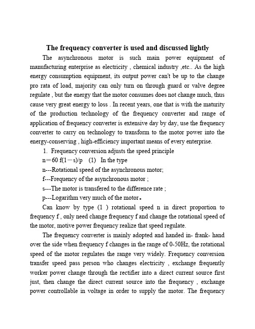
The frequency converter is used and discussed lightl yThe asynchronous motor is such main power equipment of manufacturing enterprise as electricity , chemical industry ,etc.. As the high energy consumption equipment, its output power can't be up to the change pro rata of load, majority can only turn on through guard or valve degree regulate , but the energy that the motor consumes does not change much, thus cause very great energy to loss . In recent years, one that is with the maturity of the production technology of the frequency converter and range of application of frequency converter is extensive day by day, use the frequency converter to carry on technology to transform to the motor power into the energy-conserving , high-efficiency important means of every enterprise.1. Frequency conversion adjusts the speed principlen=60 f(1-s)/p (1) In the typen---Rotational speed of the asynchronous motor;f---Frequency of the asynchronous motor ;s---The motor is transfered to the difference rate ;p---Logarithm very much of the motor。
- 1、下载文档前请自行甄别文档内容的完整性,平台不提供额外的编辑、内容补充、找答案等附加服务。
- 2、"仅部分预览"的文档,不可在线预览部分如存在完整性等问题,可反馈申请退款(可完整预览的文档不适用该条件!)。
- 3、如文档侵犯您的权益,请联系客服反馈,我们会尽快为您处理(人工客服工作时间:9:00-18:30)。
英文翻译Frequency converterPresentationThe ATV61 drive is a frequency inverter for 3-phase asynchronous motors rated between 0.75 kW and 630 kW. The drive has been designed forstate-of-the-art applications in heating, ventilationand air conditioning (HVAC) in industrial and commercial buildings: Ventilation,Air conditioning,Pumping。
The ATV61 can reduce operating costs in buildings by optimizing energycon sumption whilst improving user comfort. Its numerous integrated optionsenable it to be adapted to and incorporated into electrical installations, sophisticated control systems and building management systems. The need for electromagnetic compatibility and a reduction in harmonics were takeninto account at the outset of designing the drive. Depending on its design characteristics, each type (UL Type 1/IP 20 and/or UL Type 12/IP 54) eitherhas built-in class A or class B EMC filters and DC chokes, or these items are available as optional accessories. With its macro-configurations and “Simply Start” menu, the ATV 61 drive can beused to start up y our applications without delay and to make adjustments in virtuallyno time using user-friendly dialogue tools. designed for application is: Energy saving ratio, 2-point or 5-point quadratic ratio. Automatic catching of a spinning load with speed detection. Adaptation of current limiting according to speed. Noise and resonance suppression by means of the switching frequency which, depending on the power rating, can be set to up to 16 kHz during operation, bymodulating the switching frequency and by the frequency jump. Preset speeds. Integrated PID regulator, with preset PID references and automatic/manual.(“Auto/Man.”) mode. Electricity and service hours meter.Detection of absence of fluid, detection of zero flow rate, limiting of flow rate. Sleep function,wake-up function. Customer settings with display of physical values: bar,I/s, °C, etc.Protection functions:1 Motor and drive thermal protection, PTC thermal probe management2 Protection against overloads and overcurrents in continuous operation3 Machine mechanical protection via jump frequency function, phase rotation4 Protection of the installation by means of underload, overload and zero flow detection5 Protection via multiple fault management and configurable alarm groupsSafety functions1 Machine safety by means of the integrated “Power Removal” function。
This function prevents the motor starting accidentally; it meets the requirements of machine safety standard EN 954-1, category 3 and those of operational safety standard IEC/EN 61508, SIL2 (safety control/signalling applied to processes and systems).2 Installation safety by means of the function for forced operation with inhibition of faults, direction of operation and configurable references.Flexibility and user-friendliness:1 The ATV61 has numerous configurable logic and analog inputs and outputs in order that it can be optimised for your applications.2 It supports the Modbus and CANopen protocols as standard in order to increase the performance of your control systems. It also supports the industry’s majo communication buses and can be integrated easily into building management (HVAC) systems via option cards.The ATV61 range of variable speed drives extends across a range of motor power ratings from 0.75 kW to 630 kW with three types of power supply 。
A comprehensive offer:1 200…240 V 3-phase, 0.75 kW to 90 kW, UL Type 1/IP 20, (ATV61H M3,ATV 61H M3X)2 380…480 V 3-phase, 0.75 kW to 630 kW, UL Type 1/IP 20, (ATV61H N4)3 380…480 V 3-phase, 0.75 kW to 90 kW, UL Type 12/IP 54, (ATV61W N4,ATV61W N4C)ATV 61 UL Type 1/IP 20 drives can also be used in conjunction with motors rated between 0.37 kW and 5.5 kW on a single phase 200…240 V supply (derating is required).The ATV 61 drive integrates the Modbus and CAN open protocols as standard as well as numerous functions. These functions can be extended using communication, I/O extension and multi-pump option cards and a “Controller Inside” programmable card. Other external options, such as braking resistors, resistance braking units and filters, are available to complement this offer. The entire range conforms to international standards IEC/EN 61800-5-1,IEC/EN 61800-2, IEC/EN 61800-3, is UL, CSA, DNV,C-Tick, NOM 117 and GOST certified and has been developed to meet the requirements of the directives regarding protection of the environment (RoHS, WEEE, etc) as well of those of the European Directives governing the issuing of the _ marking. The ATV61 drive ca n be inserted in an installation’s safetysystem. It integrates the “Power Removal” safety function which prevents the motor from restarting unintentionally. The incorporation of EMC filters in ATV 61H M3 and ATV 61 N4 drives and the recognition of EMC requirements simplifies machine installation and provides a very economical means of meeting _ marking requirements.ATV 61W N4C drives feature integrated class B EMC filters, enabling them to meet the requirements of the EN 55011 (class B group 1) and IEC/EN 61800-3(category C1) standards.ATV 61H___M3X drives have been designed without an EMC filter. Filters are available as an option and can be installed by the user to reduce emission levels.The ATV61 drive has been designed to optimize the size of enclosures (floor-standing, wall-mounted, etc)。