flac3d基坑开挖计算
理正与FLAC3D计算结果

计算说明1、计算方法1)内力计算采用弹性支点法;2)土的水平抗力系数按M法确定;3)主动土压力与被动土压力采用矩形分布模式;4)采用力法分析环形内支撑内力;5)采用"理正深基坑支护结构软件FSPW 5.2"计算,计算采用单元计算与协同计算相结合,并采用FLAC-3D进行验证;6)土层参数选取2、单元计算1)基坑分为4个区,安全等级为一级,基坑重要性系数为1.1;2)荷载:施工荷载:10kPa;地面超载:4区活动荷载为25kPa,1区、2区和3区超载按10kPa考虑;水压力;基坑外侧为常水位,内侧坑底以下0.5m。
3)基坑开挖深度:根据现场地形确定,按开挖12.50m确定;4)支撑水平刚度系数:2aTsEAKL sα=式中α取0.8,E取28000MPa,L取7.0m,sa取1.20m,s取7.0m,经计算,kT 大于800 MN/m,本计算中,取800MN/m。
5)计算过程详见附件1,其中1区选用钻孔ZK1,2区选用钻孔ZK4,3区选用钻孔ZK16,4区选用钻孔ZK5。
各区计算结果汇总如下:表2 计算结果汇总表3、协同计算1)计算方法简介协同计算采用考虑支护结构、内支撑结构及土空间整体协同作用有限元的计算方法。
有限元方程如下:([K n]+[Kz]+[Kt]){W)}={F}式中:[K n]-内支撑结构的刚度矩阵;[K z]-支护结构的刚度矩阵;[Kt]-开挖面以下桩侧土抗力的刚度矩阵;{W}-位移矩阵;{F}-荷载矩阵。
计算时采用如下简化计算方法:(1)将基坑周边分成几个计算区域,同一计算区域的支护信息相同,地质条件相同。
(2)将每一个桩或每单位长度的墙看成是一个超级的子结构,这一子结构包括桩墙,土,主动和被动土压力。
(3)将第三道锚索等效为弹性支承点,作为支承系统的一部份进行计算。
(4)单独求解(2)中的子结构,可采用单桩内力计算的一套方法,将刚度和荷载凝聚到与支锚的公共节点上,这是一个一维梁计算问题。
FLAC-3D深基坑的开挖与支护的命令流

FLAC D3深基坑的开挖与支护的命令流一、实例工程南宁地区地层属于河流阶地二元地层,广泛分布有较厚的圆砾层,国内尚无在类似地层条件下建设地铁基坑的经验,为此,可使用FLAC3D 对基坑开挖的全过程进行三维数值模拟,在对比实测数据的基础上,总结圆砾层中地铁车站深基坑的地下连续墙水平变形及周围地表沉降变形特征。
该基坑位于大学路与明秀路交叉路口处,沿大学东路东西向布置。
车站基坑长465m,标准断面宽度为20.7m,为地下两层式结构,底板埋深为15.535m(相对地面),顶板覆土厚度大于3m。
本工程主体建筑面积21163.6m2,主要结构形式为双柱三跨框架箱型结构。
本工程所处的大学路为南宁市东西向的主要交通枢纽,车流量大,人流密集,地面条件复杂。
基坑施工采用明挖顺作法施工,围护结构为800mm厚地下连续墙+内撑(三道内支撑加一道换撑)的支护体系。
第一道支撑采用钢筋混凝土支撑,尺寸为800×900mm,冠梁同时作为第一道钢筋混凝土支撑的围檩。
第二、三道支撑及换撑使用钢支撑并施加预加力,直径为609mm,壁厚为t=16mm,斜撑段采用800×1000mm钢筋砼腰梁,其余为2×I45C 钢围檩。
二、模型建立建模工作由两部分组成,实体模型部分,包括土体和地下连续墙;结构单元部分,包括混凝土支撑和钢支撑。
根据对称性原理,拟选取1/2 的实际工程尺寸进行分析。
考虑到实际的基坑长度将近500m,根据以往的经验,选取全部长度的一半虽然能够得到满意的结果,但是由于中间部分的基坑基本处于同样的受力状态,这样会使大部分的计算长度变为重复的计算,降低了计算效率。
根据初步计算结果和经验,最终确定的基坑尺寸为,宽度取基坑的最大宽度24m,开挖深度19m,基坑长度36m。
根据地勘报告,合并相似土层,模型中共划分了7个土层。
在FLAC3D 中,围护结构可以用衬砌单元(liner)或实体单元模拟。
根据Zdravdovi的研究,在二维平面基坑模拟中,分别采用实体单元和梁单元(相当于三维模型中的衬砌单元)计算所产生的墙体变形差别小于4%,而引起地表沉降的主要原因是围护结构变形造成的地层损失,可见上述两种方法计算结果的差别可忽略不计。
FLAC3D在深基坑工程开挖中的数值模拟分析

随着基坑开挖深度 的增 加而加大 , 基坑 壁 向坑 内的水平位 移变 化趋势仍 然是 中间部分最 大 , 边角处 最 小, 而且基坑壁的长边 由于开挖 的范 围相对较大 , 其变形量 相对 于短边也增 大 , 这充分体 现 了基坑 开挖
过程 中的时空效应 , 数值模拟计算结果可 以为工程设计提供指导 和参考 。 关键词 : F L A C 3 D ; 深 基坑 ; 位移 ; 数值模拟 中图分类 号 : T U 4 7 0 . 3 文献标 识码 : A 文章编 号 : 1 6 7 2 _l 1 4 4 ( 2 0 1 3 ) 0 4 —0 o 1 7 —0 4
第 1 1 卷第 4期
2 0 1 3年 8月
水 利与 建筑工 程学 报
o u r n a l o f Wa t e r Re s o u r c e s a n d A r c h i t e c t u r a l E n n e e 血l g
Vo 1 . 1 1 No. 4
Ap p l i c a t i o n o f FLAC3 D i n Nu me r i c a l S i mu l a t i o n An a l y s i s f o r De e p Fo u nd a t i o n Pi t Ex av c a t i o n
t r a l b se a me n t ,t he u p l i f t g r o w s t o he t l a r g e s t v l a u e ,a n d n e r a he t f o u n d a t i o n p i t w ll a ,i t i s s ma ll e r .At t h e s a me t i me , t h e Leabharlann A u g., 201 3
深基坑开挖模拟与支护设计基于FLAC3D本科毕业论文答辩.ppt

图1 设计流程图
第二章 工程概况与场地工程地质条件
第一节:工程概况
• 武汉市万达广场深基坑工程位于武汉市江汉区,地块范围东临 新华下路,西邻新华西路,南侧为规划道路、武汉新闻出版局, 北侧为马场公寓。
• 本场地基坑分为A、B基坑两块, A、B基坑呈“吕”字型分布, 总占地面积约57000m2。A基坑为大商业部分,其地下二层主楼的 承台底标高-12.6m(电梯井-15.0m),商业部分底标高-12.4m(电梯 井-13.5m);B基坑为住宅部分,其主楼承台底标高-11.25m,分布 于基坑四周。本次设计选取A基坑OPQRSA段进行支护结构设计 与FLAC3D数值模拟。
Interval = 2.5e+004
Job Title: 深基坑工程 View Title:
Itasca Consulting Group, Inc. Minneapolis, MN USA
图4-3 初始平衡计算孔隙水压力图
FLAC3D 3.00
Step 2349 12:10:12 Sat Jun 05 2010
分段号
开挖 深度
本段特点
选择围护方案
坑外为现场施工道路; A、上部放坡卸载;
分布较厚的淤泥质土; B、支护桩+混凝土内支撑; A-OPQRSA 10.8m
有较开阔的放坡空间; C、坑壁采用粉喷桩止水;
开挖深度较深;
D、坑底采用降水井降水;
图3-1 A-OPQRSA段支护体系布置剖面图
第五节 A-OPQRSA段基坑支护桩设计
表2-1 A-OPQRSA设计开挖深度表
段号
地面标高
A-OPQRSA
20.7m
坑底标高 9.9m
开挖深度 10.8m
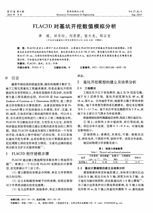
FLAC3D对基坑开挖数值模拟分析

平衡状态,此时得到的模拟计算结果见图 2 ~ 6,图 2 为
基坑 Z 方向应力云图,在模型中共分为 9 个区域,各区
域的应力值范围分别为: - 7. 3827e + 005 to - 7. 0000e
+ 005、- 7. 0000e + 005 to - 6. 0000e + 005、- 6. 0000e
536
资源环境与工程
以下取 30 m。因 此 模 型 X 方 向 长 50 m,Y 方 向 长 40 m,Z 方向长 38 m。在初始条件中,不考虑构造应 力,仅考 虑 自 重 应 力 产 生 的 初 始 应 力 场。模 型 共 有 10 500个单元,12 012 个节点( 图 1) 。
2013 年
移为 47. 35 cm,位移变形的影响范围沿基坑边缘向外约 6. 0 m。通过对位移变形矢量图及剪应变增量矢量
图分析,可知基坑边墙可能产生滑动破坏的现象。
关键词: FLAC3D; 基坑; 应力; 位移
中图分类号: TV551. 4 + 2
文献标识码: B
文章编号: 1671 - 1211( 2013) 04 - 0535 - 03
GPa,土体的体积模量 K 和剪切模量 G 与弹性模量 E 及泊松比 μ 之间的转换关系为[4]:
K
=
3(
1
E - 2μ)
( 1)
G
=
2(
E 1+
μ)
( 2)
由式( 1) 和式( 2) 计算得: 体积模量 K = 202. 90 MPa,
剪切模量 G = 110. 24 MPa。将求得的物理力学参数,
+ 005 to - 5. 0000e + 005、- 5. 0000e + 005 to -
基坑开挖模拟步骤新计算

追踪剖面选择
选择横截面“Cross section”工具箱,在(0,0,25)点附近单击。这个位置在窗旳底部将被状态键显示。同步按下《shift》键移动箭头至几何面旳其他部分。在“简介选择综合箱”选择轮廓线(Contour Lines)在观察(View)菜单检验图例(Legend)。若必要在编辑(Edit)菜单项选择择合适旳扫描线(scan line)
打开阶段窗
变化第一阶段计算类型:在K0 状态下生成初始应力场;在参数桌面,检验K0值和OCR值,见表3.1。
表3.1 参数表
1)定义建造阶段1
单击下一阶段键增长新阶段:将计算类型改为塑性(Plastic),在参数表单保持缺省设置用于迭代过程;单击”OK”键关闭阶段窗。检验各阶段列单,《Phase 1》已被选中。在y=0.0m单击开挖基坑单元,在“选择项目” 窗关闭“Soil below”选项用于模拟挖土;以一样旳方式模拟y=0.0m至y=-1.0m.此单元旳颜色将要变白表达土已被挖除。
提醒: 计算后观察成果时也能够选择节点和应力点。 在“阶段”窗去掉“ Delete intermediate steps”可精确显示曲线。
7)选择好旳观察视角
选择缩放键“Zoom”并缩放至开挖下列旳土以得到更加好旳观察视角(图3.2)。单击关闭键返回输入窗(Input window).图3.2 预览第4阶段 纯压力状态剖面图
8)关闭阶段窗口
单击下一阶段键,保持全部缺省阶段并关闭窗口。 在y=0.0m,激活分布荷载并单击“变化”键。变化y值至-20kN/m2并关闭窗口。 提醒:为检验计算状态是否被正拟定义,单击预览键,3D几何模型将出现。以此来检验单元是否激活和材料是否被设置。
9)选择应力应变观察点
在开始计算前,选择某些应力点以便于画应力应变曲线。 单击曲线选择点 打开输出项目。 经过单击选择节点和应力点,这些点也能够经过坐标选择。 为利用这些后来旳选择,从编辑菜单也可选择“网络点选择”。在“爱好点坐标”箱输入x=37.5m,y=-1.5m及z=19.0m并单击“搜索近来节点和应力点”键。
flac3d连续开挖、保存命令
endif
_excavate
思路:1.用surf2flac的代码,转换出地表,solve一下
2.在山地模型底下粘上一层标准的20米厚的矩形六面体网格
3.把那20米厚的网格中间挖出一块(煤矿采空区)
4.设定计算歩数,计算并显示Z轴位移等值线
save 20 .sav Nhomakorabea连续开挖,1500m,煤5m 计算一次。
def _excavate
_beg = 60. ; 开挖起始点
_end = _beg + 5. ; 5为开挖进尺
loop n (1,30) ; 开挖30次
;自动取名
_filename = string(n) + 'stage_excavete.sav'
loop n ( 1, 11 )
a1 = 110 + 0 + ( n*20 - 10 );model null range x= 130 , 240 y= a1 , a2 group 18;
step 500
end_command
oo=out(' --第'+string(n)+'步开挖--')
command
mo null range x _beg _end y 0 5 z 14 15.5
step 2000
save _filename
end_command
_beg = _beg + 5.
end_loop
end
请问如何实现在分步开挖的基础上嵌入不同计算步数(每运行100步自动保存)的计算?
FLAC3D模拟基础开挖
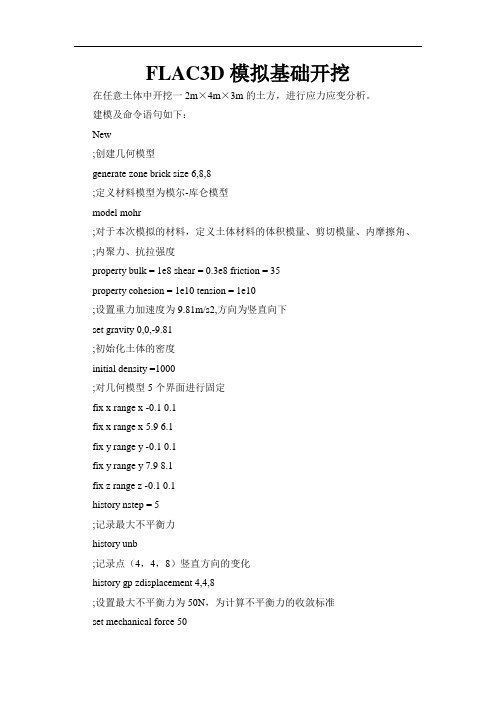
FLAC3D模拟基础开挖在已知基础中开挖一2m×4m×5m的基坑,进行应力应变分析。
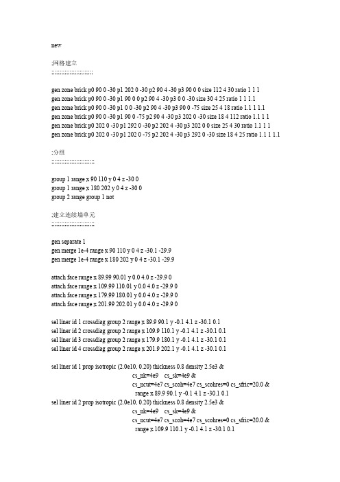
建模及命令语句如下:;简单的隧道开挖方法;第一步:初始模型的建立; 建立网格gen zone brick size 6 8 8;建立矩形的网格区域,其大小为6×8×8;指定材料的性质model mohr;采用摩尔-库仑模型prop bulk 1e8 shear 0.3e8;模型的材料性质:体积模量、剪切模量prop fric 35 coh 1e3 tens 1e3;摩擦角、粘聚力、抗拉强度;设置全局参数set grav 0,0,-9.81;设置重力加速度,z坐标正方向为正,故为-9.81ini dens 2000;初始密度为2000;设置初始边界情况fix x range x -0.1 0.1;在x 方向上固定x = 0边界,为滚动支撑fix x range x 5.9 6.1;在x 方向上固定x = 6边界,为滚动支撑fix y range y -0.1 0.1;在y 方向上固定y = 0边界,为滚动支撑fix y range y 7.9 8.1;在y 方向上固定y = 8边界,为滚动支撑fix z range z -0.1 0.1;在z 方向上固定z = 0边界,为滚动支撑;监控模型变量,并控制力学平衡hist unbal;监测不平衡力,并保留历史记录(在默认情况下,每十步做一次记录)hist gp zdisp 4,4,8;监测网格坐标点(4,4,8)在z方向的位移,并保留历史纪录solve;运算,求解pause;暂停save t1.sav;形成sav文件,并保存为t1.savpause;暂停rest t1.sav;恢复t1.sav文件; Step 2: excavate trench;第二步:开挖隧道model null range x 2,4 y 2,6 z 5,10;在x(2,4)y(2.,6)z(5,10 )范围内建立零模型(即开挖这一部分区域)pause;暂停set large;在全局下设置大应变状态initial xdis 0.0 ydis 0.0 zdis 0.0;把x,y,z重新设置为0(因为我们只为了观察基坑引起的位移变化,;而不是从施加重力荷载引起的位移变化,这不会影响计算结果)pause;暂停step 1000;运算1000步pause;暂停save t2.sav;形成sav文件,并保存为t2.savret;放在批处理文件的最后,以返回3DFLAC 的控制状态最后得到的结果如下:图1初始应力等值线云图图2 初始位移等值线云图图3 初始最大不平衡力云图图4 竖向应力等值线云图图5 位移等值线云图。
(完整word版)用flac3d模拟基坑开挖
new;网格建立;;;;;;;;;;;;;;;;;;;;;;;;;gen zone brick p0 90 0 -30 p1 202 0 -30 p2 90 4 -30 p3 90 0 0 size 112 4 30 ratio 1 1 1gen zone brick p0 90 0 -30 p1 90 0 0 p2 90 4 -30 p3 0 0 -30 size 30 4 25 ratio 1 1 1.1gen zone brick p0 90 0 -30 p1 0 0 -30 p2 90 4 -30 p3 90 0 -75 size 25 4 18 ratio 1.1 1 1.1gen zone brick p0 90 0 -30 p1 90 0 -75 p2 90 4 -30 p3 202 0 -30 size 18 4 112 ratio 1.1 1 1 gen zone brick p0 202 0 -30 p1 292 0 -30 p2 202 4 -30 p3 202 0 0 size 25 4 30 ratio 1.1 1 1 gen zone brick p0 202 0 -30 p1 202 0 -75 p2 202 4 -30 p3 292 0 -30 size 18 4 25 ratio 1.1 1 1.1;分组;;;;;;;;;;;;;;;;;;;;;;;;;;group 1 range x 90 110 y 0 4 z -30 0group 1 range x 180 202 y 0 4 z -30 0group 2 range group 1 not;建立连续墙单元;;;;;;;;;;;;;;;;;;;;;;;;;;gen separate 1gen merge 1e-4 range x 90 110 y 0 4 z -30.1 -29.9gen merge 1e-4 range x 180 202 y 0 4 z -30.1 -29.9attach face range x 89.99 90.01 y 0.0 4.0 z -29.9 0attach face range x 109.99 110.01 y 0.0 4.0 z -29.9 0attach face range x 179.99 180.01 y 0.0 4.0 z -29.9 0attach face range x 201.99 202.01 y 0.0 4.0 z -29.9 0sel liner id 1 crossdiag group 2 range x 89.9 90.1 y -0.1 4.1 z -30.1 0.1sel liner id 2 crossdiag group 2 range x 109.9 110.1 y -0.1 4.1 z -30.1 0.1sel liner id 3 crossdiag group 2 range x 179.9 180.1 y -0.1 4.1 z -30.1 0.1sel liner id 4 crossdiag group 2 range x 201.9 202.1 y -0.1 4.1 z -30.1 0.1sel liner id 1 prop isotropic (2.0e10, 0.20) thickness 0.8 density 2.5e3 &cs_nk=4e9 cs_sk=4e9 &cs_ncut=4e7 cs_scoh=4e7 cs_scohres=0 cs_sfric=20.0 &range x 89.9 90.1 y -0.1 4.1 z -30.1 0.1sel liner id 2 prop isotropic (2.0e10, 0.20) thickness 0.8 density 2.5e3 &cs_nk=4e9 cs_sk=4e9 &cs_ncut=4e7 cs_scoh=4e7 cs_scohres=0 cs_sfric=20.0 &range x 109.9 110.1 y -0.1 4.1 z -30.1 0.1sel liner id 3 prop isotropic (2.0e10, 0.20) thickness 0.8 density 2.5e3 &cs_nk=4e9 cs_sk=4e9 &cs_ncut=4e7 cs_scoh=4e7 cs_scohres=0 cs_sfric=20.0 &range x 179.9 180.1 y -0.1 4.1 z -30.1 0.1sel liner id 4 prop isotropic (2.0e10, 0.20) thickness 0.8 density 2.5e3 &cs_nk=4e9 cs_sk=4e9 &cs_ncut=4e7 cs_scoh=4e7 cs_scohres=0 cs_sfric=20.0 &range x 201.9 202.1 y -0.1 4.1 z -30.1 0.1;定义支撑结构;;;;;;;;;;;;;;;;;;;;;;;def struct_install1loop i(1,3)structx_zz=-1.0*5.0*(i-1)structx_xx0=90.0structx_xx1=110.0structx_yy=2.0commandsel beam id=2 begin (structx_xx0,structx_yy,structx_zz) end (structx_xx1,structx_yy,structx_zz) nseg=10sel beam id=2 prop dens=0.000 emod=1.0e-6 nu=0.2 &xcarea=0.80 xcj=10.94e-2 xciy=6.67e-2 xciz=4.27e-2 ydirection=(0 0 -1) ;1000x800endcommandendloopendstruct_install1def struct_install2loop i(1,3)structx_zz=-1.0*5.0*(i-1)structx_xx0=180.0structx_xx1=202.0structx_yy=2.0commandsel beam id=3 begin (structx_xx0,structx_yy,structx_zz) end (structx_xx1,structx_yy,structx_zz) nseg=11sel beam id=3 prop dens=0.000 emod=1.0e-6 nu=0.2 &xcarea=0.80 xcj=10.94e-2 xciy=6.67e-2 xciz=4.27e-2 ydirection=(0 0 -1) ;1000x800endcommandendloopendstruct_install2;建立结构单元分组;;;;;;;;;;;;;;;;;;;;;;;;;;;sel group linerwall range sel linersel group struct1 range sel beam x (90.0 110.0) z (-0.1 0.1)sel group struct2 range sel beam x (90.0 110.0) z (-5.1 -4.9)sel group struct3 range sel beam x (90.0 110.0) z (-10.1 -9.9)sel group struct4 range sel beam x (180.0 202.0) z (-0.1 0.1)sel group struct5 range sel beam x (180.0 202.0) z (-5.1 -4.9)sel group struct6 range sel beam x (180.0 202.0) z (-10.1 -9.9);删除beam单元的linksel dele link range sel beam z (-30 0);建立liner间的节点间的刚性linkdef merge_link0node_num=0node_pnt0 = nd_headloop while node_pnt0 # null ;寻找总节点数,注:不能自己任生成node,程序缺省的方式为连续生成无不连续node_num = node_num+1node_pnt0 = nd_next(node_pnt0)endloopnode_num_minus1 = node_num-1link_id=30000loop ii (1,node_num_minus1)node_pnt1 = nd_find(ii)xxa = nd_pos(node_pnt1,2,1)yya = nd_pos(node_pnt1,2,2)zza = nd_pos(node_pnt1,2,3)ii_plus1 = ii+1loop jj (ii_plus1,node_num)node_pnt2 = nd_find(jj)xxb = nd_pos(node_pnt2,2,1)yyb = nd_pos(node_pnt2,2,2)zzb = nd_pos(node_pnt2,2,3)node_dist = sqrt((xxa-xxb)^2+(yya-yyb)^2+(zza-zzb)^2)dist_tol = 1e-1if node_dist <= dist_tol thenlink_pnt1 = nd_link(node_pnt1)link_pnt2 = nd_link(node_pnt2);if link_pnt1 # null then; temp1 = lk_delete(link_pnt1);endifif link_pnt2 # null thentemp2 = lk_delete(link_pnt2)endiflink_id = link_id+1command ;生成新link(6自由度全固结),大的node的id作为target node,小的node的id作为source node,需注意不同情况下的灵活调整sel set link node_tol=dist_tolsel link id=link_id jj target = node tgt_num =ii ;指定link的ID;sel link ii target = node tgt_num = jj ;不指定link的id,自动生成sel link attach xdir=rigid ydir=rigid zdir=rigid xrdir=rigid yrdir=rigid zrdir=rigid range id=link_idendcommandendifendloopendloopendmerge_link0;设置土层材料参数;;;;;;;;;;;;;;;;;;;;;;;;;;;;def b_s_modb_mod =e_mod/(3.0*(1.0-2.0*p_ratio))s_mod =e_mod/(2.0*(1.0+p_ratio))endmodel elasticset e_mod 100e6set p_ratio 0.3b_s_modprop bu=b_mod sh=s_modini dens 1800 range z -75 0def ini_szzszz0=0szzgrad=1800*10commandini szz add szz0 grad 0 0 szzgrad range z -75 0endcommandendini_szzdef ini_sxx_syypnt=zone_headloop while pnt # nullval=k0*z_szz(pnt)z_sxx(pnt)=valz_syy(pnt)=valpnt=z_next(pnt)endloopendset k0=0.50ini_sxx_syy;定义边界处的结构边界条件;;;;;;;;;;;;;;;;;;;;;;;;;;;;;;;;cyc 0sel node local xdir=(0,1,0) ydir=(0,0,1) range x 89.9 90.1 y -0.1 4.1 z -30.1 0.1 sel node local xdir=(0,1,0) ydir=(0,0,-1) range x 109.9 110.1 y -0.1 4.1 z -30.1 0.1 sel node local xdir=(0,1,0) ydir=(0,0,1) range x 179.9 180.1 y -0.1 4.1 z -30.1 0.1 sel node local xdir=(0,1,0) ydir=(0,0,-1) range x 201.9 202.1 y -0.1 4.1 z -30.1 0.1sel node fix lsys range x 89.9 90.1 y -0.1 0.1 z -30.1 0.1sel node fix lsys range x 89.9 90.1 y 3.9 4.1 z -30.1 0.1sel node fix lsys range x 109.9 110.1 y -0.1 0.1 z -30.1 0.1sel node fix lsys range x 109.9 110.1 y 3.9 4.1 z -30.1 0.1sel node fix lsys range x 179.9 180.1 y -0.1 0.1 z -30.1 0.1sel node fix lsys range x 179.9 180.1 y 3.9 4.1 z -30.1 0.1sel node fix lsys range x 201.9 202.1 y -0.1 0.1 z -30.1 0.1sel node fix lsys range x 201.9 202.1 y 3.9 4.1 z -30.1 0.1sel node fix x yr zr range x 89.9 90.1 y -0.1 0.1 z -30.1 0.1sel node fix x yr zr range x 89.9 90.1 y 3.9 4.1 z -30.1 0.1sel node fix x yr zr range x 109.9 110.1 y -0.1 0.1 z -30.1 0.1sel node fix x yr zr range x 109.9 110.1 y 3.9 4.1 z -30.1 0.1sel node fix x yr zr range x 179.9 180.1 y -0.1 0.1 z -30.1 0.1sel node fix x yr zr range x 179.9 180.1 y 3.9 4.1 z -30.1 0.1sel node fix x yr zr range x 201.9 202.1 y -0.1 0.1 z -30.1 0.1sel node fix x yr zr range x 201.9 202.1 y 3.9 4.1 z -30.1 0.1sel node fix y range x 89.9 90.1 y 0.0 4.0 z -0.1 0.1sel node fix y range x 109.9 110.1 y 0.0 4.0 z -0.1 0.1sel node fix y range x 179.9 180.1 y 0.0 4.0 z -0.1 0.1sel node fix y range x 201.9 202.1 y 0.0 4.0 z -0.1 0.1;set plot meta;plot set rot 20 0 30 ba wh color=on cent=(10 20 0) mag=3.81;set outp node_local_sys.wmf;plot add sel geom black red link=off node=off id=off shrink=0 scale=0.03 nodesys=on range group linerwall any group struct1 any;pl ha;固定边界条件;;;;;;;;;;;;;;;;;;;;;;;;;;fix x range x -0.1 0.1fix x range x 291.9 292.1fix y range y -0.1 0.1fix y range y 3.9 4.1fix x y z range z -75.1 -74.9set grav 0,0,-10solvesave elas.sav;删除侧面内外土体间的连接约束;;;;;;;;;;;;;;;;;;;;;;;;;;;;;;;;;;;;;;;;attach delete range x 89.99 90.01 y 0.0 4.0 z -29.9 0attach delete range x 109.99 110.01 y 0.0 4.0 z -29.9 0attach delete range x 179.99 180.01 y 0.0 4.0 z -29.9 0attach delete range x 201.99 202.01 y 0.0 4.0 z -29.9 0;在墙内土体的外侧建立接触面;;;;;;;;;;;;;;;;;;;;;;;;;;;;;;;;;;;;;;;;interface 1 face range group 1 x 89.99 90.01 y 0.0 4.0 z -29.9 0interface 2 face range group 1 x 109.99 110.01 y 0.0 4.0 z -29.9 0interface 3 face range group 1 x 179.99 180.01 y 0.0 4.0 z -29.9 0interface 4 face range group 1 x 201.99 202.01 y 0.0 4.0 z -29.9 0interface 1 prop kn=4e8 ks=4e8 tens=5e3 coh=0.0 fric=20 ;接触面参数interface 2 prop kn=4e8 ks=4e8 tens=5e3 coh=0.0 fric=20 ;接触面参数interface 3 prop kn=4e8 ks=4e8 tens=5e3 coh=0.0 fric=20 ;接触面参数interface 4 prop kn=4e8 ks=4e8 tens=5e3 coh=0.0 fric=20 ;接触面参数interface 1 maxedge=1interface 2 maxedge=1interface 3 maxedge=1interface 4 maxedge=1;interface 1 prop kn=4e8 ks=4e8 tens=1e10 sbratio=100;plot set ba wh;pl ske interface red blue attach cyan green;set outp interface_attachment.wmf;pl ha;重新定义连续墙参数;;;;;;;;;;;;;;;;;;;;;;;;;;;;;;;;sel liner id 1 prop isotropic (2.0e10, 0.20) &cs_nk=4e9 cs_sk=4e9 &cs_scoh=4e7 cs_scohres=0.0 cs_sfric=0.0 range x 89.9 90.1 y -0.1 4.1 z -30.1 0.1sel liner id 2 prop isotropic (2.0e10, 0.20) &cs_nk=4e9 cs_sk=4e9 &cs_scoh=4e7 cs_scohres=0.0 cs_sfric=0.0 range x 109.9 110.1 y-0.1 4.1 z -30.1 0.1sel liner id 3 prop isotropic (2.0e10, 0.20) &cs_nk=4e9 cs_sk=4e9 &cs_scoh=4e7 cs_scohres=0.0 cs_sfric=0.0 range x 179.9 180.1 y -0.1 4.1 z -30.1 0.1sel liner id 4 prop isotropic (2.0e10, 0.20) &cs_nk=4e9 cs_sk=4e9 &cs_scoh=4e7 cs_scohres=0.0 cs_sfric=0.0 range x 201.9 202.1 y -0.1 4.1 z -30.1 0.1;重新定义墙底约束条件;;;;;;;;;;;;;;;;;;;;;;;;;;;;;;;;def redef_wall_end_link1node_pnt = nd_headlink_id=100000loop while node_pnt # nullnode_id = nd_id(node_pnt)xx = nd_pos(node_pnt,2,1)yy = nd_pos(node_pnt,2,2)zz = nd_pos(node_pnt,2,3)link_pnt = nd_link(node_pnt)dist_x = sqrt((xx-90.0)^2+(zz+30.0)^2)if dist_x <=dist_tol thenif link_pnt # null thentemp1 = lk_delete(link_pnt)\link_id = link_id+1commandsel set link node_tol = dist_tolsel link id=link_id node_id target zonesel link attach xdir=rigid ydir=rigid zdir=rigid xrdir=free yrdir=free zrdir=free range id=link_idendcommandendifendifnode_pnt = nd_next(node_pnt)endloopendredef_wall_end_link1def redef_wall_end_link2node_pnt = nd_headlink_id=150000loop while node_pnt # nullnode_id = nd_id(node_pnt)xx = nd_pos(node_pnt,2,1)yy = nd_pos(node_pnt,2,2)zz = nd_pos(node_pnt,2,3)link_pnt = nd_link(node_pnt)dist_x = sqrt((xx-110.0)^2+(zz+30.0)^2)dist_tol = 1e-1if dist_x <=dist_tol thenif link_pnt # null thenif yy < 85.0temp1 = lk_delete(link_pnt)\link_id = link_id+1commandsel set link node_tol = dist_tolsel link id=link_id node_id target zonesel link attach xdir=rigid ydir=rigid zdir=rigid xrdir=free yrdir=free zrdir=free range id=link_idendcommandendifendifendifnode_pnt = nd_next(node_pnt)endloopendredef_wall_end_link2def redef_wall_end_link3node_pnt = nd_headlink_id=200000loop while node_pnt # nullnode_id = nd_id(node_pnt)xx = nd_pos(node_pnt,2,1)yy = nd_pos(node_pnt,2,2)zz = nd_pos(node_pnt,2,3)link_pnt = nd_link(node_pnt)dist_x = sqrt((xx-180.0)^2+(zz+30.0)^2)dist_tol = 1e-1if dist_x <=dist_tol thenif link_pnt # null thentemp1 = lk_delete(link_pnt)\link_id = link_id+1commandsel set link node_tol = dist_tolsel link id=link_id node_id target zonesel link attach xdir=rigid ydir=rigid zdir=rigid xrdir=free yrdir=free zrdir=free range id=link_idendcommandendifendifnode_pnt = nd_next(node_pnt)endloopendredef_wall_end_link3def redef_wall_end_link4node_pnt = nd_headlink_id=250000loop while node_pnt # nullnode_id = nd_id(node_pnt)xx = nd_pos(node_pnt,2,1)yy = nd_pos(node_pnt,2,2)zz = nd_pos(node_pnt,2,3)link_pnt = nd_link(node_pnt)dist_x = sqrt((xx-202.0)^2+(zz+30.0)^2)dist_tol = 1e-1if dist_x <=dist_tol thenif link_pnt # null thentemp1 = lk_delete(link_pnt)\link_id = link_id+1commandsel set link node_tol = dist_tolsel link id=link_id node_id target zonesel link attach xdir=rigid ydir=rigid zdir=rigid xrdir=free yrdir=free zrdir=free range id=link_idendcommandendifendifnode_pnt = nd_next(node_pnt)endloopendredef_wall_end_link4;剑桥模型;;;;;;;;;;;;;;;;;;;;;;;;;;;;;;;;;;;;;;model cam-clay;cam-clay模型则不需定义弹性模量(E、G、K)等参数,自动计算;cam-clay模型中需确定8个模型参数(①-⑧),手册property中的初始比体积cv(v0)和shear 无须给定def install_proppnt=zone_headloop while pnt # nullabs_sxx=abs(z_sxx(pnt)) ;|sxx|abs_syy=abs(z_syy(pnt)) ;|syy|abs_szz=abs(z_szz(pnt)) ;|szz|p0=(abs_sxx+abs_syy+abs_szz)/3.0;cam-clay模型中p、q均须为正值,p0由初应力场确定,故cam-clam定义模型参数前须先已知初应力p0_effective=p0-z_pp(pnt) ;p0';q0=sqrt(((abs_sxx-abs_syy)^2+(abs_syy-abs_szz)^2+(abs_szz-abs_sxx)^2)*0.5)q0=sqrt(((abs_sxx-abs_syy)^2+(abs_syy-abs_szz)^2+(abs_szz-abs_sxx)^2)*0.5+3.0*((z_sxy(pnt)) ^2+(z_sxz(pnt))^2+(z_syz(pnt))^2))z_prop(pnt,'mm')=6.0*sin(fai*degrad)/(3.0-sin(fai*degrad)) ;①注三角函数中需将角度转化为弧度temp1=q0/(z_prop(pnt,'mm')*p0_effective)pc0=p0_effective*(1.0+temp1^2)*OCR ;先期有效固结压力,用于确定屈服面v0=1.0+_e0z_prop(pnt,'cam_cp')=p0_effective ;★重要参数,否则不能正确计算有效应力,提示出错"Mean effective pressure is negative"z_prop(pnt,'mpc')=pc0 ;②z_prop(pnt,'poisson')=p_ratio ;③z_prop(pnt,'lambda')=_lambda ;④z_prop(pnt,'kappa')=_kappa ;⑤z_prop(pnt,'mp1')=_mp1 ;⑥z_prop(pnt,'mv_l')=v0+_lambda*ln(2.0*_cu/(z_prop(pnt,'mm')*_mp1))+(_lambda-_kappa)*l n(2.0) ;⑦z_prop(pnt,'bulk_bound')=100*40e6 ;⑧;z_prop(pnt,'bulk_bound')=100*(s_mod+4.0/3.0*s_mod) ;弹性体模上界Kmax;自动确定Kmax时会出现“property bad”错误提示;因为弹性上界对计算结果无影响,在不提示Kmax太小的性况下,取值越小计算收敛越快pnt=z_next(pnt)endloopendset p_ratio=0.25 fai=34.5 _lambda=0.14 _kappa=0.012 _mp1=1e3 _e0=1.2 _cu=10e3 OCR=1.0 ;模型所需参数install_propsolvesave model_cam.sav。
flac3d模拟基坑开挖

3.5 计算模型计算模型见图3-3~图3-5,X轴为水平方向,Y轴为竖直方向。
本模型采用实体单元模拟土体、桩、筏板,其中素混凝土桩长5m,筏板厚2m,筏板嵌入土层0.4m。
模型中共有12730个网格点,12542个实体单元。
图3-3 计算模型图图3-4 开挖完后模型图图3-5 筏板、桩、空洞模型图3.5 模拟计算工况计算过程先对计算域进行初始应力场平衡计算,然后模拟计算地基开挖过程,最后模拟地基土的加固,并施加竖向荷载。
计算分析地基中存在空洞时上层土层开挖后产生的卸荷回弹,以及采用筏板及置换桩加固并施加压力后土层的沉降量4 计算结果及分析为便于分析空洞部位的位移应力,对模型中的4个空洞进行编号,见图4-1。
计算结果中竖向位移向上为正,向下为负;应力以拉为正,压为负。
图4-1 空洞示意图4.1 地基中不存在空洞上层土层开挖后的竖向位移分布见图4-2,由图可知,地基开挖完后在开挖面产生较大的反弹,最大回弹位移为17.8cm。
在空洞附近,回弹量比相同高程土层要大,且最大回弹位移均发生在空洞上表面,4个空洞四周的回弹位移极值见表4-1,其中1#空洞虽然埋深较深,但由于其尺寸较大,其最大回弹量与埋深较浅的2#空洞、3#空洞接近,4#空洞则由于埋深较深,且尺寸较小,其最大回弹量也相当较小。
表4-1 地基开挖后空洞四周位移极值统计图4-2 地基开挖完后竖向位移分布云图采用混凝土桩加固,并在筏板上施加荷载后地基位移变化量分布见图4-3。
由图可知,地基加固后并施加荷载后地基土产生了一定的沉降量,在场地中央的最大沉降量为3.8cm。
空洞上表面的沉降量比相同高程的土层大,下表面的沉降量则比相同高程的土层小,空洞最大沉降量均发生在上表面,最小沉降量均发生在下表面,空洞四周的位移极值统计见表4-2,1#空洞尽管其尺寸相对较大,但由于其位于场地边缘,且埋深较深,施加荷载后位移相对较小;尺寸及埋深接近的2#、3#空洞沉降量基本一致;4#空洞虽然埋深较深且尺寸较小,但由于其更接近作用力中心,故产生的沉降量与埋深较浅的2#、3#空洞基本一致。
基于FLAC3D的地铁车站深基坑开挖变形三维数值分析

d e e p e x c a v a i t o n s i s i n v e s t i g a t e d t h r o u g h n u me i r c  ̄a n a l y s i s wi t h s i t e s p e c i i f c s u b s u fa r c e c o n it d i o n s ,b a s e d o n t h e a n l a y t i c a l r e s u l t s ,t h e
冯勇慧 王跃军 董建华 ( 甘肃第三建设集团公司,甘肃 兰州 7 3 0 0 3 0 )
摘 要 :以 某 地铁 车 站 深 基 坑 工 程 为 依 托 ,介 绍 了该 工 程 拟 建 场 区的 周 边 环 境 、 水 文 地 质 条 件 以及 支护 结 构 选 型 。根
据工程 特点将其 分为六个典型工况 ,运用 F L A C3 D建立三维数值模 型对基坑开挖进行数值模 拟计 算, 旨在研 究 “ 钻孔咬合 桩 + 内支撑 ”这 一支护 结构在地铁 车站深基坑工程施工 中的 变形规律 ,分析 了其水平位移 、钢 支撑轴 力及其周 围土体的沉 降规律和沉 降影 响范围。并根据 支撑位 置的不同对深基坑 变形 的影 响,对该基坑 工程 的支护设计 方案进行 了优化 。通过与 原方案 的对 比,得 出优化 方案在控制 变形等 方面有一 定的改善 。本 文的研 究成果 可为今后地铁 车站深基坑工程的合理设计 与安全施工提供 参考。
t he b or e d pi l e s a nd i nt e ior r s u ppo r t . The a na l y s i s of t he hor iz o nt a l de f o r ma t i o n of t he r e t a i n i n g s t r uc t u r e s ,t he a x i a l f or c e c ha ng e s o f s t e e l s up por t,t h e s e t t l e me nt l a w a n d t he i nf l ue nc e s phe r e of s u ̄ou nd i ng s o i l . Fo r i ns t a l l a ion t o f pr o p s t r uc t ur e s o n t he pe r f o m a r nc e o f
FLAC3D对基坑开挖数值模拟分析
的手 段 , 在基 坑工 程 中得 到 广 泛 的 应 用 。本 文 以某 地 区基 坑 开挖 为背 景 , 运 用 有 限 差 分 法计 算 模 拟 基 坑 开 挖后 周 围土体 的变 形 和受力 情况 。为 基坑 边 墙 的稳 定 性 分析 及支 护方 式提 供依 据 … 。
② 粉质粘土 : 黄褐 色、 灰 黑 色, 可 塑 。摇 振 反 应 无, 稍有 光泽 , 干 强度 中等 , 韧 性 中等 。该 层分 布连 续 。 地层 的物 理力 学参 数见 表 1 。
A n a l y s i s o f C o n t i n u a i n 3 D i m e n s i o n s的简 写 , 是 三 维 岩 体 力学 有 限差分 计 算 机 程 序 。 由著 名 的 国 际学 者 P e —
t e r C u n d a l l 博 士 开 发 的 面 向 土木 建 筑 、 采 矿、 交通 、 水
( 2 )定义 本构 模 型 和 赋 予 材 料参 数 , 来 限 定 模 型 对 于外 界 扰动做 出的变化 规 律 ;
于基 坑 为轴对 称 图形 , 因此取基 坑 的 1 / 4建立 模 型 。
( 3 )定义边界条件 、 初始条件 , 来定义模型的初始
为了减少边界条件对计算结果的影响 , 在 x轴上 向基 坑外 取 3 0 m, 在 Y轴 上 向基 坑 外侧 取 3 1 m, 基 坑底 面
阶地 。地下水类型为第四系孔隙潜水。稳定水位埋深
为9 . 3~1 1 . 5 m。地 下水位 年变 化幅度 约为 2 . 0 m, 该
利、 地质 、 石 油及 环境 工程 的通 用软 件 系统 。可 以对 土 质、 岩 石或 其它 材料 进行 三维 岩土 工程 三 维数 值 分析 。 F L A C 3 D可 以解 决分 步 开挖 、 大 变 形 及 大应 变 、 非 线 性 和非 稳定 系统 等有 限元难 以实现 的诸 多 复杂 的 工程 问
FLAC 3D在软土基坑开挖计算中的应用
对 所 有 的 网格 节 点
Aol r 2:2 Ae ( o1 G l 2 A 2=Ao2) r " I
A 3 r o]=O ( e +A 2 lA1 2 1 e) 2 式中 l=K+(/ ) ;2=K一(/ ) 43 G O / 2 3 G;K为体积
模量 ;G为剪切模量 。
一
A 2=O A i+ ( e r o l e 2A +△ ; l e)
() 6
A 3=OA ;+O ( e r o l e l △ +△ ; 1 2 e)
式 中 O =K+ G 3 l= 1 . 4 / ;O K一 G 3 , 2/。 2 3 2 屈服 函数 ..
根据 主 应力 排 序 ,破 坏 准 则 在 平 面 ( ,o ) r 描述见 图 2 ,由 M h —C u m or ol b屈服 函数可得 到点 A o
A= [ u ÷芸 aA … j ]
式中
Aol r l:卢1 el+卢 Ae2 A1 2 2 Ao 2 I A l l 2 r B e1+ Ae2 2 2
( 2 )
△, e为应变张量增量 ;矗 为位移量 ;A 为时步 。 i , t
在 平面应 力条件下 ,模 型的应 力 一 变增量 表达 应 式为
关 键 词 软 土
1 F A 概 述 L Cຫໍສະໝຸດ 基 坑 开挖数值 分析
FA 如 LC
在平面应变条件下 ,模 型的应力 一应变增量 表达 式 由胡克定律得
Aol = O1 l r1 t Ae J+ O2 2 lAe2 Ao2 r2 O2 l l Ae1+ O1 2 tAe2 , 1、
・
16・ 6
全 国中文核心期 刊
FLAC3D模拟基础开挖2
FLAC3D模拟基础开挖在任意土体中开挖一2m×4m×3m的土方,进行应力应变分析。
建模及命令语句如下:New;创建几何模型generate zone brick size 6,8,8;定义材料模型为模尔-库仑模型model mohr;对于本次模拟的材料,定义土体材料的体积模量、剪切模量、内摩擦角、;内聚力、抗拉强度property bulk = 1e8 shear = 0.3e8 friction = 35property cohesion = 1e10 tension = 1e10;设置重力加速度为9.81m/s2,方向为竖直向下set gravity 0,0,-9.81;初始化土体的密度initial density =1000;对几何模型5个界面进行固定fix x range x -0.1 0.1fix x range x 5.9 6.1fix y range y -0.1 0.1fix y range y 7.9 8.1fix z range z -0.1 0.1history nstep = 5;记录最大不平衡力history unb;记录点(4,4,8)竖直方向的变化history gp zdisplacement 4,4,8;设置最大不平衡力为50N,为计算不平衡力的收敛标准set mechanical force 50;进行计算Solve;暂停后,查看应力图,而进行应力与模型的验证Pause;重新赋与土体材料参数property cohesion = 1e3 tension = 1e3;对土体进行开挖model null range x = 2,4 y=2,6 z=5,10;设置变形为大变形set large;网格节点位移全部清零initial xdisplacement=0 ydisplacement=0 zdisplacement=0 ;求解step 2000图1 最大不平衡力图2 记录点随时步竖直位移曲线通过图1与图2可知初始应力基本与实际符合,接着输入“continue”进行开挖计算。
FLAC_3D_在深基坑开挖与支护数值模拟中的应用

第27卷第3期 岩 土 力 学 V ol.27 No.3 2006年3月 Rock and Soil Mechanics Mar. 2006收稿日期:2004-08-16 修改稿收到日期:2004-12-07作者简介:刘继国,男,1976年生,硕士,工程师,主要从事隧道与地下工程方面的设计和研究工作。
E-mail:liujiguogg@文章编号:1000-7598-(2006) 03-0505-04FLAC 3D 在深基坑开挖与支护数值模拟中的应用刘继国1,曾亚武2(1.中交第二公路勘察设计研究院,武汉 430052;2.武汉大学 土木建筑工程学院,武汉 430072)摘 要: 运用FLAC 3D 软件对武汉长江过江隧道江南明挖段深基坑进行了开挖与支护模拟。
计算中采用摩尔-库仑弹塑性模型,基坑围护结构与土体之间的接触面运用接触单元。
通过计算得出不同开挖阶段的地表沉降、基底隆起和墙后土体水平位移,为工程设计与施工提供参考。
关 键 词:FLAC 3D ;接触;基坑开挖与支护 中图分类号:TU 470 文献标识码:AApplication of FLAC 3D to simulation of foundation excavation and supportLIU Ji-guo 1, ZENG Ya-wu 2(1.Second Highway Survey Design and Research Institute, Ministry of Communications, Wuhan 430052, China;2. School of Civil and Architectural Engineering, Wuhan University, Wuhan 430072, China)Abstract: The simulation of excavation and support on the deep pit of the Yangtze River in south was carried out using the software FLAC 3D . During the simulation, the Mohr-Coulomb model was used and contact elements were applied on the interfaces between the structure and soil. This simulation offers the settlements of ground uplifts in the bottom of the pit and horizontal displacements of the soil behind the vertical wall in every step.Key words: FLAC 3D ; contact; foundation pit excavation and support1 引 言在高层建筑及其他工程深基坑施工过程中,支护结构与土相互作用,不断调整自身受力与变形,使基坑内外土体保持稳定或失稳状态,这是一个机理复杂的力学过程[1]。
(整理)FLAC3d基坑模拟

计算说明1、计算方法1)内力计算采用弹性支点法;2)土的水平抗力系数按M法确定;3)主动土压力与被动土压力采用矩形分布模式;4)采用力法分析环形内支撑内力;5)采用"理正深基坑支护结构软件FSPW 5.2"计算,计算采用单元计算与协同计算相结合,并采用FLAC-3D进行验证;6)土层参数选取2、单元计算1)基坑分为4个区,安全等级为一级,基坑重要性系数为1.1;2)荷载:施工荷载:10kPa;地面超载:4区活动荷载为25kPa,1区、2区和3区超载按10kPa考虑;水压力;基坑外侧为常水位,内侧坑底以下0.5m。
3)基坑开挖深度:根据现场地形确定,按开挖12.50m确定;4)支撑水平刚度系数:2aTsEAKL sα=式中α取0.8,E取28000MPa,L取7.0m,sa取1.20m,s取7.0m,经计算,kT 大于800 MN/m,本计算中,取800MN/m。
5)计算过程详见附件1,其中1区选用钻孔ZK1,2区选用钻孔ZK4,3区选用钻孔ZK16,4区选用钻孔ZK5。
各区计算结果汇总如下:表2 计算结果汇总表3、协同计算1)计算方法简介协同计算采用考虑支护结构、内支撑结构及土空间整体协同作用有限元的计算方法。
有限元方程如下:([K n]+[Kz]+[Kt]){W)}={F}式中:[K n]-内支撑结构的刚度矩阵;[K z]-支护结构的刚度矩阵;[Kt]-开挖面以下桩侧土抗力的刚度矩阵;{W}-位移矩阵;{F}-荷载矩阵。
计算时采用如下简化计算方法:(1)将基坑周边分成几个计算区域,同一计算区域的支护信息相同,地质条件相同。
(2)将每一个桩或每单位长度的墙看成是一个超级的子结构,这一子结构包括桩墙,土,主动和被动土压力。
(3)将第三道锚索等效为弹性支承点,作为支承系统的一部份进行计算。
(4)单独求解(2)中的子结构,可采用单桩内力计算的一套方法,将刚度和荷载凝聚到与支锚的公共节点上,这是一个一维梁计算问题。
(完整word版)用flac3d模拟基坑开挖
new;网格建立;;;;;;;;;;;;;;;;;;;;;;;;;gen zone brick p0 90 0 -30 p1 202 0 -30 p2 90 4 -30 p3 90 0 0 size 112 4 30 ratio 1 1 1gen zone brick p0 90 0 -30 p1 90 0 0 p2 90 4 -30 p3 0 0 -30 size 30 4 25 ratio 1 1 1.1gen zone brick p0 90 0 -30 p1 0 0 -30 p2 90 4 -30 p3 90 0 -75 size 25 4 18 ratio 1.1 1 1.1gen zone brick p0 90 0 -30 p1 90 0 -75 p2 90 4 -30 p3 202 0 -30 size 18 4 112 ratio 1.1 1 1 gen zone brick p0 202 0 -30 p1 292 0 -30 p2 202 4 -30 p3 202 0 0 size 25 4 30 ratio 1.1 1 1 gen zone brick p0 202 0 -30 p1 202 0 -75 p2 202 4 -30 p3 292 0 -30 size 18 4 25 ratio 1.1 1 1.1;分组;;;;;;;;;;;;;;;;;;;;;;;;;;group 1 range x 90 110 y 0 4 z -30 0group 1 range x 180 202 y 0 4 z -30 0group 2 range group 1 not;建立连续墙单元;;;;;;;;;;;;;;;;;;;;;;;;;;gen separate 1gen merge 1e-4 range x 90 110 y 0 4 z -30.1 -29.9gen merge 1e-4 range x 180 202 y 0 4 z -30.1 -29.9attach face range x 89.99 90.01 y 0.0 4.0 z -29.9 0attach face range x 109.99 110.01 y 0.0 4.0 z -29.9 0attach face range x 179.99 180.01 y 0.0 4.0 z -29.9 0attach face range x 201.99 202.01 y 0.0 4.0 z -29.9 0sel liner id 1 crossdiag group 2 range x 89.9 90.1 y -0.1 4.1 z -30.1 0.1sel liner id 2 crossdiag group 2 range x 109.9 110.1 y -0.1 4.1 z -30.1 0.1sel liner id 3 crossdiag group 2 range x 179.9 180.1 y -0.1 4.1 z -30.1 0.1sel liner id 4 crossdiag group 2 range x 201.9 202.1 y -0.1 4.1 z -30.1 0.1sel liner id 1 prop isotropic (2.0e10, 0.20) thickness 0.8 density 2.5e3 &cs_nk=4e9 cs_sk=4e9 &cs_ncut=4e7 cs_scoh=4e7 cs_scohres=0 cs_sfric=20.0 &range x 89.9 90.1 y -0.1 4.1 z -30.1 0.1sel liner id 2 prop isotropic (2.0e10, 0.20) thickness 0.8 density 2.5e3 &cs_nk=4e9 cs_sk=4e9 &cs_ncut=4e7 cs_scoh=4e7 cs_scohres=0 cs_sfric=20.0 &range x 109.9 110.1 y -0.1 4.1 z -30.1 0.1sel liner id 3 prop isotropic (2.0e10, 0.20) thickness 0.8 density 2.5e3 &cs_nk=4e9 cs_sk=4e9 &cs_ncut=4e7 cs_scoh=4e7 cs_scohres=0 cs_sfric=20.0 &range x 179.9 180.1 y -0.1 4.1 z -30.1 0.1sel liner id 4 prop isotropic (2.0e10, 0.20) thickness 0.8 density 2.5e3 &cs_nk=4e9 cs_sk=4e9 &cs_ncut=4e7 cs_scoh=4e7 cs_scohres=0 cs_sfric=20.0 &range x 201.9 202.1 y -0.1 4.1 z -30.1 0.1;定义支撑结构;;;;;;;;;;;;;;;;;;;;;;;def struct_install1loop i(1,3)structx_zz=-1.0*5.0*(i-1)structx_xx0=90.0structx_xx1=110.0structx_yy=2.0commandsel beam id=2 begin (structx_xx0,structx_yy,structx_zz) end (structx_xx1,structx_yy,structx_zz) nseg=10sel beam id=2 prop dens=0.000 emod=1.0e-6 nu=0.2 &xcarea=0.80 xcj=10.94e-2 xciy=6.67e-2 xciz=4.27e-2 ydirection=(0 0 -1) ;1000x800endcommandendloopendstruct_install1def struct_install2loop i(1,3)structx_zz=-1.0*5.0*(i-1)structx_xx0=180.0structx_xx1=202.0structx_yy=2.0commandsel beam id=3 begin (structx_xx0,structx_yy,structx_zz) end (structx_xx1,structx_yy,structx_zz) nseg=11sel beam id=3 prop dens=0.000 emod=1.0e-6 nu=0.2 &xcarea=0.80 xcj=10.94e-2 xciy=6.67e-2 xciz=4.27e-2 ydirection=(0 0 -1) ;1000x800endcommandendloopendstruct_install2;建立结构单元分组;;;;;;;;;;;;;;;;;;;;;;;;;;;sel group linerwall range sel linersel group struct1 range sel beam x (90.0 110.0) z (-0.1 0.1)sel group struct2 range sel beam x (90.0 110.0) z (-5.1 -4.9)sel group struct3 range sel beam x (90.0 110.0) z (-10.1 -9.9)sel group struct4 range sel beam x (180.0 202.0) z (-0.1 0.1)sel group struct5 range sel beam x (180.0 202.0) z (-5.1 -4.9)sel group struct6 range sel beam x (180.0 202.0) z (-10.1 -9.9);删除beam单元的linksel dele link range sel beam z (-30 0);建立liner间的节点间的刚性linkdef merge_link0node_num=0node_pnt0 = nd_headloop while node_pnt0 # null ;寻找总节点数,注:不能自己任生成node,程序缺省的方式为连续生成无不连续node_num = node_num+1node_pnt0 = nd_next(node_pnt0)endloopnode_num_minus1 = node_num-1link_id=30000loop ii (1,node_num_minus1)node_pnt1 = nd_find(ii)xxa = nd_pos(node_pnt1,2,1)yya = nd_pos(node_pnt1,2,2)zza = nd_pos(node_pnt1,2,3)ii_plus1 = ii+1loop jj (ii_plus1,node_num)node_pnt2 = nd_find(jj)xxb = nd_pos(node_pnt2,2,1)yyb = nd_pos(node_pnt2,2,2)zzb = nd_pos(node_pnt2,2,3)node_dist = sqrt((xxa-xxb)^2+(yya-yyb)^2+(zza-zzb)^2)dist_tol = 1e-1if node_dist <= dist_tol thenlink_pnt1 = nd_link(node_pnt1)link_pnt2 = nd_link(node_pnt2);if link_pnt1 # null then; temp1 = lk_delete(link_pnt1);endifif link_pnt2 # null thentemp2 = lk_delete(link_pnt2)endiflink_id = link_id+1command ;生成新link(6自由度全固结),大的node的id作为target node,小的node的id作为source node,需注意不同情况下的灵活调整sel set link node_tol=dist_tolsel link id=link_id jj target = node tgt_num =ii ;指定link的ID;sel link ii target = node tgt_num = jj ;不指定link的id,自动生成sel link attach xdir=rigid ydir=rigid zdir=rigid xrdir=rigid yrdir=rigid zrdir=rigid range id=link_idendcommandendifendloopendloopendmerge_link0;设置土层材料参数;;;;;;;;;;;;;;;;;;;;;;;;;;;;def b_s_modb_mod =e_mod/(3.0*(1.0-2.0*p_ratio))s_mod =e_mod/(2.0*(1.0+p_ratio))endmodel elasticset e_mod 100e6set p_ratio 0.3b_s_modprop bu=b_mod sh=s_modini dens 1800 range z -75 0def ini_szzszz0=0szzgrad=1800*10commandini szz add szz0 grad 0 0 szzgrad range z -75 0endcommandendini_szzdef ini_sxx_syypnt=zone_headloop while pnt # nullval=k0*z_szz(pnt)z_sxx(pnt)=valz_syy(pnt)=valpnt=z_next(pnt)endloopendset k0=0.50ini_sxx_syy;定义边界处的结构边界条件;;;;;;;;;;;;;;;;;;;;;;;;;;;;;;;;cyc 0sel node local xdir=(0,1,0) ydir=(0,0,1) range x 89.9 90.1 y -0.1 4.1 z -30.1 0.1 sel node local xdir=(0,1,0) ydir=(0,0,-1) range x 109.9 110.1 y -0.1 4.1 z -30.1 0.1 sel node local xdir=(0,1,0) ydir=(0,0,1) range x 179.9 180.1 y -0.1 4.1 z -30.1 0.1 sel node local xdir=(0,1,0) ydir=(0,0,-1) range x 201.9 202.1 y -0.1 4.1 z -30.1 0.1sel node fix lsys range x 89.9 90.1 y -0.1 0.1 z -30.1 0.1sel node fix lsys range x 89.9 90.1 y 3.9 4.1 z -30.1 0.1sel node fix lsys range x 109.9 110.1 y -0.1 0.1 z -30.1 0.1sel node fix lsys range x 109.9 110.1 y 3.9 4.1 z -30.1 0.1sel node fix lsys range x 179.9 180.1 y -0.1 0.1 z -30.1 0.1sel node fix lsys range x 179.9 180.1 y 3.9 4.1 z -30.1 0.1sel node fix lsys range x 201.9 202.1 y -0.1 0.1 z -30.1 0.1sel node fix lsys range x 201.9 202.1 y 3.9 4.1 z -30.1 0.1sel node fix x yr zr range x 89.9 90.1 y -0.1 0.1 z -30.1 0.1sel node fix x yr zr range x 89.9 90.1 y 3.9 4.1 z -30.1 0.1sel node fix x yr zr range x 109.9 110.1 y -0.1 0.1 z -30.1 0.1sel node fix x yr zr range x 109.9 110.1 y 3.9 4.1 z -30.1 0.1sel node fix x yr zr range x 179.9 180.1 y -0.1 0.1 z -30.1 0.1sel node fix x yr zr range x 179.9 180.1 y 3.9 4.1 z -30.1 0.1sel node fix x yr zr range x 201.9 202.1 y -0.1 0.1 z -30.1 0.1sel node fix x yr zr range x 201.9 202.1 y 3.9 4.1 z -30.1 0.1sel node fix y range x 89.9 90.1 y 0.0 4.0 z -0.1 0.1sel node fix y range x 109.9 110.1 y 0.0 4.0 z -0.1 0.1sel node fix y range x 179.9 180.1 y 0.0 4.0 z -0.1 0.1sel node fix y range x 201.9 202.1 y 0.0 4.0 z -0.1 0.1;set plot meta;plot set rot 20 0 30 ba wh color=on cent=(10 20 0) mag=3.81;set outp node_local_sys.wmf;plot add sel geom black red link=off node=off id=off shrink=0 scale=0.03 nodesys=on range group linerwall any group struct1 any;pl ha;固定边界条件;;;;;;;;;;;;;;;;;;;;;;;;;;fix x range x -0.1 0.1fix x range x 291.9 292.1fix y range y -0.1 0.1fix y range y 3.9 4.1fix x y z range z -75.1 -74.9set grav 0,0,-10solvesave elas.sav;删除侧面内外土体间的连接约束;;;;;;;;;;;;;;;;;;;;;;;;;;;;;;;;;;;;;;;;attach delete range x 89.99 90.01 y 0.0 4.0 z -29.9 0attach delete range x 109.99 110.01 y 0.0 4.0 z -29.9 0attach delete range x 179.99 180.01 y 0.0 4.0 z -29.9 0attach delete range x 201.99 202.01 y 0.0 4.0 z -29.9 0;在墙内土体的外侧建立接触面;;;;;;;;;;;;;;;;;;;;;;;;;;;;;;;;;;;;;;;;interface 1 face range group 1 x 89.99 90.01 y 0.0 4.0 z -29.9 0interface 2 face range group 1 x 109.99 110.01 y 0.0 4.0 z -29.9 0interface 3 face range group 1 x 179.99 180.01 y 0.0 4.0 z -29.9 0interface 4 face range group 1 x 201.99 202.01 y 0.0 4.0 z -29.9 0interface 1 prop kn=4e8 ks=4e8 tens=5e3 coh=0.0 fric=20 ;接触面参数interface 2 prop kn=4e8 ks=4e8 tens=5e3 coh=0.0 fric=20 ;接触面参数interface 3 prop kn=4e8 ks=4e8 tens=5e3 coh=0.0 fric=20 ;接触面参数interface 4 prop kn=4e8 ks=4e8 tens=5e3 coh=0.0 fric=20 ;接触面参数interface 1 maxedge=1interface 2 maxedge=1interface 3 maxedge=1interface 4 maxedge=1;interface 1 prop kn=4e8 ks=4e8 tens=1e10 sbratio=100;plot set ba wh;pl ske interface red blue attach cyan green;set outp interface_attachment.wmf;pl ha;重新定义连续墙参数;;;;;;;;;;;;;;;;;;;;;;;;;;;;;;;;sel liner id 1 prop isotropic (2.0e10, 0.20) &cs_nk=4e9 cs_sk=4e9 &cs_scoh=4e7 cs_scohres=0.0 cs_sfric=0.0 range x 89.9 90.1 y -0.1 4.1 z -30.1 0.1sel liner id 2 prop isotropic (2.0e10, 0.20) &cs_nk=4e9 cs_sk=4e9 &cs_scoh=4e7 cs_scohres=0.0 cs_sfric=0.0 range x 109.9 110.1 y-0.1 4.1 z -30.1 0.1sel liner id 3 prop isotropic (2.0e10, 0.20) &cs_nk=4e9 cs_sk=4e9 &cs_scoh=4e7 cs_scohres=0.0 cs_sfric=0.0 range x 179.9 180.1 y -0.1 4.1 z -30.1 0.1sel liner id 4 prop isotropic (2.0e10, 0.20) &cs_nk=4e9 cs_sk=4e9 &cs_scoh=4e7 cs_scohres=0.0 cs_sfric=0.0 range x 201.9 202.1 y -0.1 4.1 z -30.1 0.1;重新定义墙底约束条件;;;;;;;;;;;;;;;;;;;;;;;;;;;;;;;;def redef_wall_end_link1node_pnt = nd_headlink_id=100000loop while node_pnt # nullnode_id = nd_id(node_pnt)xx = nd_pos(node_pnt,2,1)yy = nd_pos(node_pnt,2,2)zz = nd_pos(node_pnt,2,3)link_pnt = nd_link(node_pnt)dist_x = sqrt((xx-90.0)^2+(zz+30.0)^2)if dist_x <=dist_tol thenif link_pnt # null thentemp1 = lk_delete(link_pnt)\link_id = link_id+1commandsel set link node_tol = dist_tolsel link id=link_id node_id target zonesel link attach xdir=rigid ydir=rigid zdir=rigid xrdir=free yrdir=free zrdir=free range id=link_idendcommandendifendifnode_pnt = nd_next(node_pnt)endloopendredef_wall_end_link1def redef_wall_end_link2node_pnt = nd_headlink_id=150000loop while node_pnt # nullnode_id = nd_id(node_pnt)xx = nd_pos(node_pnt,2,1)yy = nd_pos(node_pnt,2,2)zz = nd_pos(node_pnt,2,3)link_pnt = nd_link(node_pnt)dist_x = sqrt((xx-110.0)^2+(zz+30.0)^2)dist_tol = 1e-1if dist_x <=dist_tol thenif link_pnt # null thenif yy < 85.0temp1 = lk_delete(link_pnt)\link_id = link_id+1commandsel set link node_tol = dist_tolsel link id=link_id node_id target zonesel link attach xdir=rigid ydir=rigid zdir=rigid xrdir=free yrdir=free zrdir=free range id=link_idendcommandendifendifendifnode_pnt = nd_next(node_pnt)endloopendredef_wall_end_link2def redef_wall_end_link3node_pnt = nd_headlink_id=200000loop while node_pnt # nullnode_id = nd_id(node_pnt)xx = nd_pos(node_pnt,2,1)yy = nd_pos(node_pnt,2,2)zz = nd_pos(node_pnt,2,3)link_pnt = nd_link(node_pnt)dist_x = sqrt((xx-180.0)^2+(zz+30.0)^2)dist_tol = 1e-1if dist_x <=dist_tol thenif link_pnt # null thentemp1 = lk_delete(link_pnt)\link_id = link_id+1commandsel set link node_tol = dist_tolsel link id=link_id node_id target zonesel link attach xdir=rigid ydir=rigid zdir=rigid xrdir=free yrdir=free zrdir=free range id=link_idendcommandendifendifnode_pnt = nd_next(node_pnt)endloopendredef_wall_end_link3def redef_wall_end_link4node_pnt = nd_headlink_id=250000loop while node_pnt # nullnode_id = nd_id(node_pnt)xx = nd_pos(node_pnt,2,1)yy = nd_pos(node_pnt,2,2)zz = nd_pos(node_pnt,2,3)link_pnt = nd_link(node_pnt)dist_x = sqrt((xx-202.0)^2+(zz+30.0)^2)dist_tol = 1e-1if dist_x <=dist_tol thenif link_pnt # null thentemp1 = lk_delete(link_pnt)\link_id = link_id+1commandsel set link node_tol = dist_tolsel link id=link_id node_id target zonesel link attach xdir=rigid ydir=rigid zdir=rigid xrdir=free yrdir=free zrdir=free range id=link_idendcommandendifendifnode_pnt = nd_next(node_pnt)endloopendredef_wall_end_link4;剑桥模型;;;;;;;;;;;;;;;;;;;;;;;;;;;;;;;;;;;;;;model cam-clay;cam-clay模型则不需定义弹性模量(E、G、K)等参数,自动计算;cam-clay模型中需确定8个模型参数(①-⑧),手册property中的初始比体积cv(v0)和shear 无须给定def install_proppnt=zone_headloop while pnt # nullabs_sxx=abs(z_sxx(pnt)) ;|sxx|abs_syy=abs(z_syy(pnt)) ;|syy|abs_szz=abs(z_szz(pnt)) ;|szz|p0=(abs_sxx+abs_syy+abs_szz)/3.0;cam-clay模型中p、q均须为正值,p0由初应力场确定,故cam-clam定义模型参数前须先已知初应力p0_effective=p0-z_pp(pnt) ;p0';q0=sqrt(((abs_sxx-abs_syy)^2+(abs_syy-abs_szz)^2+(abs_szz-abs_sxx)^2)*0.5)q0=sqrt(((abs_sxx-abs_syy)^2+(abs_syy-abs_szz)^2+(abs_szz-abs_sxx)^2)*0.5+3.0*((z_sxy(pnt)) ^2+(z_sxz(pnt))^2+(z_syz(pnt))^2))z_prop(pnt,'mm')=6.0*sin(fai*degrad)/(3.0-sin(fai*degrad)) ;①注三角函数中需将角度转化为弧度temp1=q0/(z_prop(pnt,'mm')*p0_effective)pc0=p0_effective*(1.0+temp1^2)*OCR ;先期有效固结压力,用于确定屈服面v0=1.0+_e0z_prop(pnt,'cam_cp')=p0_effective ;★重要参数,否则不能正确计算有效应力,提示出错"Mean effective pressure is negative"z_prop(pnt,'mpc')=pc0 ;②z_prop(pnt,'poisson')=p_ratio ;③z_prop(pnt,'lambda')=_lambda ;④z_prop(pnt,'kappa')=_kappa ;⑤z_prop(pnt,'mp1')=_mp1 ;⑥z_prop(pnt,'mv_l')=v0+_lambda*ln(2.0*_cu/(z_prop(pnt,'mm')*_mp1))+(_lambda-_kappa)*l n(2.0) ;⑦z_prop(pnt,'bulk_bound')=100*40e6 ;⑧;z_prop(pnt,'bulk_bound')=100*(s_mod+4.0/3.0*s_mod) ;弹性体模上界Kmax;自动确定Kmax时会出现“property bad”错误提示;因为弹性上界对计算结果无影响,在不提示Kmax太小的性况下,取值越小计算收敛越快pnt=z_next(pnt)endloopendset p_ratio=0.25 fai=34.5 _lambda=0.14 _kappa=0.012 _mp1=1e3 _e0=1.2 _cu=10e3 OCR=1.0 ;模型所需参数install_propsolvesave model_cam.sav。
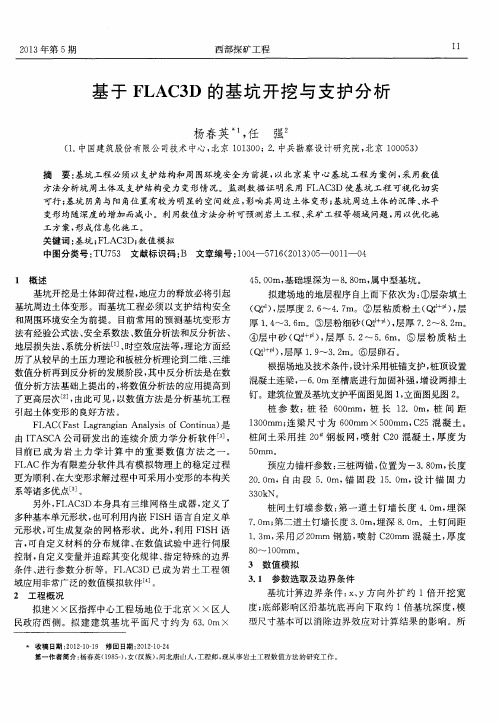
基于FLAC3D的基坑开挖与支护分析
3 . 1 参数选 取 及边界 条件
基 坑计算 边 界 条 件 : x 、 Y方 向外 扩 约 1倍 开 挖 宽 度; 底 部影 响区沿基 坑底 再 向下取 约 1倍 基 坑深 度 , 模 型尺寸 基本可 以消除 边 界效 应 对计 算 结 果 的影 响 。所
拟 建 × ×区指挥 中 心工 程 场地 位 于北 京 × ×区人 民政府 西 侧 。拟 建 建 筑 基 坑 平 面 尺 寸 约 为 6 3 . 0 mx
基坑周边土体变形 。而基坑工程必须 以支护结构安全 和周 围环境 安全 为前提 。 目前 常用 的预 } 贝 4 基 坑 变形 方 法有 经验公式 法 、 安 全系数 法 、 数值 分析法 和反分 析法 、 地层损 失法 、 系统分 析法l _ 1 ] 、 时空 效应法 等 , 理 论方 面经 历 了从 较早 的土压力理 论 和板 桩分析 理论 到二维 、 三维 数值分 析再 到反分析 的发展 阶段 , 其 中反分 析法是 在数 值 分析 方法基 础上提 出的 , 将 数值分 析法 的应 用提 高到 了更高层次[ 2 ] , 由此可见 , 以数值方法是分析基 坑工程 引起土 体变形 的 良好方 法 。
工方案 , 形成信 息化施 工 。
关 键词 : 基坑 ; F I A C 3 D; 数值模拟
中图分类 号 : TU7 5 3 文献标 识码 : B 文章编 号 : 1 。 0 4 —5 7 1 6 ( 2 0 1 3 ) O 5 一。 0 1 1 —0 4
1 概 述
4 5 . 0 0 m, 基 础埋 深为 一8 . 8 0 m, 属 中型基坑 。
基坑开 挖是 土体卸荷 过程 , 地 应力 的释放必 将 引起
拟建场 地 的地层程 序 自上而下 依次 为 : ①层 杂填 土 ( ) , 层 厚度 2 . 6 ~4 . 7 m。② 层 粘 质 粉 土 ( Q i p 1 ) , 层
- 1、下载文档前请自行甄别文档内容的完整性,平台不提供额外的编辑、内容补充、找答案等附加服务。
- 2、"仅部分预览"的文档,不可在线预览部分如存在完整性等问题,可反馈申请退款(可完整预览的文档不适用该条件!)。
- 3、如文档侵犯您的权益,请联系客服反馈,我们会尽快为您处理(人工客服工作时间:9:00-18:30)。
gen zon brick p0 20 0 20.5 p1 21.07 0 20.5 p2 20 12 20.5 p3 20 0 23.5 size 2 6 3 ratio 1 1 1 group 1
gen zon brick p0 0 13.07 13.5 p1 20 13.07 13.5 p2 0 42 13.5 p3 0 13.07 20.5 size 10 10 5 ratio 1 1.14 1 group 2
gen zon brick p0 0 13.07 20.5 p1 20 13.07 20.5 p2 0 42 20.5 p3 0 13.07 23.5 size 10 10 3 ratio 1 1.14 1 group 1
gen zon brick p0 0 13.07 0 p1 20 13.07 0 p2 0 42 0 p3 0 13.07 3.5 size 10 10 3 ratio 1 1.14 1 group 4
gen zon brick p0 0 13.07 3.5 p1 20 13.07 3.5 p2 0 42 3.5 p3 0 13.07 13.5 size 10 10 5 ratio 1 1.14 1 group 3
gen zon brick p0 0 0 -1.5 p1 20 0 -1.5 p2 0 12 -1.5 p3 0 0 0 size 10 6 3 ratio 1 1 1 group 4
gen zon brick p0 0 0 -5 p1 20 0 -5 p2 0 12 -5 p3 0 0 -1.5 size 10 6 2 ratio 1 1 1 group 5
gen zon brick p0 0 13.07 -1.5 p1 20 13.07 -1.5 p2 0 42 -1.5 p3 0 13.07 0 size 10 10 3 ratio 1 1.14 1 group 4
gen zon brick p0 0 13.07 -5 p1 20 13.07 -5 p2 0 42 -5 p3 0 13.07 -1.5 size 10 10 2 ratio 1 1.14 1 group 5
gen zon brick p0 20 0 -1.5 p1 21.07 0 -1.5 p2 20 12 -1.5 p3 20 0 0 size 2 6 3 ratio 1 1 1 group 4
gen zon brick p0 20 0 -5 p1 21.07 0 -5 p2 20 12 -5 p3 20 0 -1.5 size 2 6 2 ratio 1 1 1 group 5
gen zon brick p0 21.07 12 -1.5 p1 50 12 -1.5 p2 21.07 13.07 -1.5 p3 21.07 12 0 size 10 2 3 ratio 1.14 1 1 group 4
gen zon brick p0 21.07 12 -5 p1 50 12 -5 p2 21.07 13.07 -5 p3 21.07 12 -1.5 size 10 2 2 ratio 1.14 1 1 group 5
gen zon brick p0 0 0 13.5 p1 20 0 13.5 p2 0 12 13.5 p3 0 0 20.5 size 10 6 5 ratio 1 1 1 group 2
gen zon brick p0 0 0 20.5 p1 20 0 20.5 p2 0 12 20.5 p3 0 0 23.5 size 10 6 3 ratio 1 1 1 group 1
gen zon brick p0 21.07 12 13.5 p1 50 12 13.5 p2 21.07 13.07 13.5 p3 21.07 12 20.5 size 10 2 5 ratio 1.14 1 1 group 2
gen zon brick p0 21.07 12 20.5 p1 50 12 20.5 p2 21.07 13.07 20.5 p3 21.07 12 23.5 size 10 2 3 ratio 1.14 1 1 group 1
gen zon brick p0 21.07 0 13.5 p1 50 0 13.5 p2 21.07 12 13.5 p3 21.07 0 20.5 size 10 6 5 ratio 1.14 1 1 group 2
gen zon brick p0 21.07 0 20.5 p1 50 0 20.5 p2 21.07 12 20.5 p3 21.07 0 23.5 size 10 6 3 ratio 1.14 1 1 group 1
gen zon brick p0 0 12 13.5 p1 20 12 13.5 p2 0 13.07 13.5 p3 0 12 20.5 size 10 2 5 ratio 1 1 1 group 2
gen zon brick p0 0 12 20.5 p1 20 12 20.5 p2 0 13.07 20.5 p3 0 12 23.5 size 10 2 3 ratio 1 1 1 group 1
gen zon brick p0 20 12 0 p1 21.07 12 0 p2 20 13.07 0 p3 20 12 3.5 size 2 2 3 ratio 1 1 1 group 4
gen zon brick p0 20 12 3.5 p1 21.07 12 3.5 p2 20 13.07 3.5 p3 20 12 13.5 size 2 2 5 ratio 1 1 1 group 3
new
;建模
gen zon brick p0 0 0 0 p1 20 0 0 p2 0 12 0 p3 0 0 3.5 size 10 6 3 ratio 1 1 1 group 4
gen zon brick p0 0 0 3.5 p1 20 0 3.5 p2 0 12 3.5 p3 0 0 13.5 size 10 6 5 ratio 1 1 1 group 3
gen zon brick p0 20 13.07 0 p1 21.07 13.07 0 p2 20 42 0 p3 20 13.07 3.5 size 2 10 3 ratio 1 1.14 1 group 4
gen zon brick p0 20 13.07 3.5 p1 21.07 13.07 3.5 p2 20 42 3.5 p3 20 13.07 13.5 size 2 10 5 ratio 1 1.14 1 group 3
gen zon brick p0 0 12 -1.5 p1 20 12 -1.5 p2 0 13.07 -1.5 p3 0 12 0 size 10 2 3 ratio 1 1 1 group 4
gen zon brick p0 0 12 -5 p1 20 12 -5 p2 0 13.07 -5 p3 0 12 -1.5 size 10 2 2 ratio 1 1 1 group 5
gen zon brick p0 20 0 0 p1 21.07 0 0 p2 20 12 0 p3 20 0 3.5 size 2 6 3 ratio 1 1 1 group 4
gen zon brick p0 20 0 3.5 p1 21.07 0 3.5 p2 20 12 3.5 p3 20 0 13.5 size 2 6 5 ratio 1 1 1 group 3
gen zon brick p0 20 13.07 -1.5 p1 21.07 13.07 -1.5 p2 20 42 -1.5 p3 20 13.07 0 size 2 10 3 ratio 1 1.14 1 group 4
gen zon brick p0 20 13.07 -5 p1 21.07 13.07 -5 p2 20 42 -5 p3 20 13.07 -1.5 size 2 10 2 ratio 1 1.14 1 group 5
gen zon brick p0 20 12 13.5 p1 21.07 12 13.5 p2 20 13.07 13.5 p3 20 12 20.5 size 2 2 5 ratio 1 1 1 group 2
gen zon brick p0 20 12 20.5 p1 21.07 12 20.5 p2 20 13.07 20.5 p3 20 12 23.5 size 2 2 3 ratio 1 1 1 group 1
gen zon brick p0 20 13.07 13.5 p1 21.07 13.07 13.5 p2 20 42 13.5 p3 20 13.07 20.5 size 2 10 5 ratio 1 1.14 1 group 2
gen zon brick p0 20 13.07 20.5 p1 21.07 13.07 20.5 p2 20 42 20.5 p3 20 13.07 23.5 size 2 10 3 ratio 1 1.14 1 group 1
gen zon brick p0 21.07 12 0 p1 50 12 0 p2 21.07 13.07 0 p3 21.07 12 3.5 size 10 2 3 ratio 1.14 1 1 group 4
gen zon brick p0 21.07 12 3.5 p1 50 12 3.5 p2 0 2 5 ratio 1.14 1 1 group 3
gen zon brick p0 0 12 0 p1 20 12 0 p2 0 13.07 0 p3 0 12 3.5 size 10 2 3 ratio 1 1 1 group 4