WS2815-Mini规格书
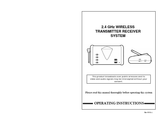
2.4GHz 无线传输接收器系统用户手册说明书
Poor reception
Causes and remedies
Camera
Receiver
- No camera (or other video - AC adapter not plugged in
device) connected to
- Power switch not turned on
- Adjust antenna direction
- Adjust antenna direction
FOR MORE INFORMATION
Because our products are subject to continuous improvement, SVC Reserves the right to modify product design and specifications without Notice and without incurring any obligation. E & OE.
CAUTION
!
RISK OF ELECTRIC SHOCK. DO NOT OPEN.
CAUTION:TO REDUCE THE RISK OF ELECTRIC SHOCK, DO NOT REMOVE COVER (OR BACK). NO USER-SERVICEABLE PARTS INSIDE. REFER SERVICING TO QUALIFIED SERVICE PERSONNEL.
WS2815-Mini规格书
回流焊说明
1.回流焊不可以做两次以上 2.当回焊时,不要在材料受热时用力压胶体表面
烙铁焊接说明:
1.当手工焊接时,烙铁的温度必须小于 300℃,时间不可超过 3 秒 2.手工焊接只可焊接一次
修补说明:
LED 回流焊后不应该修补,当修复是不可避免时,必须使用双头烙铁 (如下图),但必须事先确认此种方 式会或不会损坏 LED 本身的特性。
液相温度(TL) 液相区保温时间(tL)
峰值温度(Tp) 高温区(峰值温度-5℃)停留时间(tp)
降温速率 室温至峰值温度停留时间
WS2815-Mini
智能外控集成 LED 光源
无铅回流焊 150℃ 200℃
60-180 S <3℃/S 217℃ 60-150 S 245℃ <10 S <6℃/S <6 min
1. 通过使用适当的工具从材料侧面夹取
2. 不可直接用手或尖锐金属压胶体表面,它可能会损坏内部电路
3. 不可将模组材料堆积在一起,它可能会损坏内部电路
4.不可用在 PH<7 的酸性场所
6/6
5/6
WS2815-Mini
智能外控集成 LED 光源 3. 除湿处理
LED 产品超出以上规定期限,或者由于其他原因受潮,建议客户做除湿处理后再使用。 除湿方法:70℃-75℃/48±2 小时。
4. 静电防护
LED 是静电敏感器件,虽然 LED 产品具有优异的抗静电能力,但每经历一次静电释放产生的冲击, 都会对 LED 造成一定程度的损坏。因而在使用 LED 产品过程中需要做好静电防护措施, 例如佩戴防静电手套及防静 电手环等。
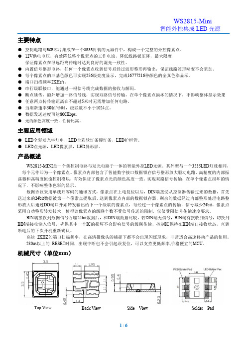
机械尺寸(单位mm)
Top View
Back View
100G QSFP28 模块商品说明书

Yes
HDX: U2NM2-S5C
(4x100G-LR)
e2XHD: ULE2XHDA024NHKDS5
N/A
HDX: U2LM2-21C e2XHD: ULE2XHD-
A024CHLES4
QDD-2x100-CWDM4-S SM 2 x CS
Yes (2x100GCWDM4)
HDX: U2LM2-21C
Guide Public
Leviton Cabling Guide for Cisco 100G and 400G Optics
100G QSFP28 MODULES
Cisco P/N
Media
Connector Interface
Breakout
Leviton Near End Cassette P/N
Lane (Near End/Far
Speed
End)
HDX Example (Breakout Side)
QDD-400G-SR4-BD
Yes
HDX: 5FUHD-6MB
HDX: 5FUHD-6MP
HDX: 42LM2-21C
MM
MPO12
(4x40/100GSRBD)
e2XHD: E2XHD-4MB
Leviton Far End Cassette P/N
Leviton Far End
Breakout HDX Example
Breakout Cassette Lane (Near End/Far
P/N
Speed
End)
HDX Example (Breakout Side)
QSFP-100G-SR4-S
[E]
8F Array cord, OM4
MSA2815S中文资料
1
元器件交易网
MSA SERIES
DC/DC CONVERTERS
5 WATT
ABSOLUTE MAXIMUM RATINGS
Input Voltage • 16 to 40 V
Output Power • 5 watts
Lead Soldering Temperature (10 sec per lead) • 300°C
WIDE VOLTAGE RANGE
The MSA converters are designed to provide full power operation over a full 16 to 40 VDC voltage range. Operation below 16 volts, including MIL-STD-704E emergency power conditions is possible with derated power. Please refer to the low line dropout graphs (Figures 17 and 18) for details. A low voltage lockout feature keeps the converter shutdown below approximately 13 VDC to ensure smooth initialization.
工厂中英文版本无线充电蓝牙音箱规格书模板范本

一:概述Introduction1.1用途1.1 use多功能无线充电器是一款集蓝牙4.0和QI1.1.2无线充电标准的无线充电的电子产品,该产品可实现蓝牙手机通讯,蓝牙音箱,无线充电功能。
multifunctional wireless charger is electronic products with a set of 4 Bluetooth and QI1.1.2 wireless charging standard for wireless charging, the product have the Bluetooth mobile phone, Bluetooth speakers, wireless charging function.1.2型号The model1.3适用环境1.3 for the environmenta)环境温度:-10℃~+55℃A ) environment temperature: -10℃~ +55 ℃b)贮存温度:-25℃~+70℃B ) storage temperature: -25℃~ +70 ℃c)相对湿度:不超过85%C ): relative humidity of not more than 85%1.3技术特点1.3 technical characteristicsa)可对符合QI标准的待充电产品实现无线充电功能,免除有线的烦恼,简单通用A ) to meet the QI standard charging product of wireless charging function, avoid cable troubles, it has the simple and general way.b)可实现与手机蓝牙通讯B ) Can communicate with the mobile phone Bluetoothc)优良的蓝牙音箱音质C Excellent sound quality of Bluetooth speaker二:主要技术参数二 The main technical parameters2.1电气特性2.1 electrical characteristicsa) 输入电源:DC5V/2AThe input power supply: DC5V/2A a )b) 无线充电适配接收器:最大5W(5V/1A)B ) wireless charging adapter receiver : the maximum 5W ( 5V/1A )c)无线充电距离:≤5mmC ) wireless charging distance:≤ 5mmd)无线充电标准:QI1.1.2Wireless charging standard: QI1.1.2 d )e)充电效率:≤70%E ) charging efficiency:≤ 70%f)蓝牙功能4.0通讯标准F ) Bluetooth 4 communication standardg)蓝牙音响功率:≤3WG ) Bluetooth Audio Power:≤ 3Wh)蓝牙通讯距离:≤10mH ) Bluetooth communication distance:≤ 10mi)产品净重:130±5克I ) product net weight: 130 ±5 gramsj)带包装重量:390±10克J ) packaging weight: 390±10 gramsk)产品包装尺寸:19CM*10.8CM*5.7CMK ) product packing size: 19CM*10.8CM*5.7CM2.2外形尺寸2.2 dimensions2.3面壳玻璃镜片强度2.3 shell glass strength钢化4H,应力层深度10-13um,32g 钢珠35CM高处跌落3次不破Toughened 4H, 10-13um layer of depth, steel 32g 35CM falling 3 times is not broken三:使用说明三Instructions for use3.1无线充电3.1 wireless charginga)接通电源,无线充电指示灯(LED2三色灯)由白色变为关闭,设备处于待机状态(如图)。
HDL 第三方产品手册说明书

第三方产品手册目录公司简介背景音乐系统遮阳系统环境控制系统012325262728333437394243465254596530050608111503监测环境系统092129安防系统31照明系统357寸迷你主机/4寸迷你主机中央主机扬声器Kaiterra墙内检测仪睿石mini检测仪协议开合电机蛇形帘天棚帘转弯器、弯轨系列轨道安装技术支持中央空调网关/HOMEKIT 迷你家居款轨道条形格栅灯系列条形泛光灯系列90°可调格栅灯系列磁吸轨道灯系列吊线灯系列格栅射灯系列射灯系列212嵌入式射灯室内被动红外入侵探测器(嵌入式) S-one 智能门锁背景音乐系统高品质的音乐,不仅仅在手机、在PC端、在随身听、电视、在播放器,它更在我们人居的每一个角落中响起,同步我们最爱的歌曲,更有最恰到好处的人工语音,提醒我们家中的状态。
03页码04页码4x20W双分区 全无损格式解码专业DSP音频处理喜马拉雅网络电台超远距离蓝牙播放HD全双工对讲通话安卓6.x,7寸IPS显示屏Airplay/DLNA/Qplay推送WIFI连接,无线掌控,互联互通超强的无线实时对讲、音乐控制4英寸全面屏设计音源:本地音乐、喜马拉雅、第三方音乐APP、蓝牙、DLNA、AUX 完美适配QQ音乐、酷狗音乐等热门第三方音乐APP 支持Micro SD卡、U盘读取播放音乐支持对讲、呼叫功能,可与多台DM839或DM858进行对讲、呼叫支持AUX输入和输出功能支持RS485控制支持WIFI连接拥有定时功能三种情景播放模式和自定义模式选择:Party、Sleep、Relax、Customize 支持门铃联动DM858极简风格UI 超全的曲库最精准的推荐最懂你的音乐伴侣只因云雀之声便知流水雀鸟之音温馨的呼叫通话你我之间只是一键的距离有我就是幸福一家DM839因为相信 所以相遇 追梦路上 无所畏惧 每一段拼搏旅程都彰显着不平凡4寸迷你主机独特的气场 豪华的气质 丰富节目源 8-72分区殿堂级音质 8-12区自由点播与推送无线DLNA推送全无损格式解码2x100W+14x30W在线升级APP全宅无线控制4分区每分区2x30W/8Ω100-240V / 50/60Hz交换机/“手拉手”级联支持无线控制备注:AM8300只配套AM8328使用中央主机AM8328它,天生的王者 它,无限的潜力 它,殿堂级音质流畅的线条,磨砂的表面 你是别墅的主人 它是你一生的伴侣分区扩展机AM830006页码AUX168II功率:20W/8Ω 喇叭单元:6.5"x1,1" x1 最大声压级:102±2dB 有效频率范围:60Hz-20,000Hz 灵敏度:89±2dB规格:97×Ø233mm 开孔尺寸:205-210mm 净重:1.6kgAUX167II功率:20W/8Ω 喇叭单元:5"x1,1"x1 最大声压级:102±2dB 有效频率范围:100Hz-20,000Hz 灵敏度:87±2dB规格:78×Ø205mm 开孔尺寸:180-185mm净重:0.55kgAUX521功率:10W/8Ω 喇叭单元:6.5"x1, 0.75"x1 最大声压级:103±2dB 有效频率范围:90Hz-18KHz 灵敏度:93±2dB规格:70×Ø190mm 开孔尺寸:168-172mm净重:1.0kgAUX644功率:15W/8Ω 喇叭单元:5"x1 最大声压级: 98±2dB 有效频率范围:150Hz-20kHz 灵敏度:86±2dB 规格:280×225×298mm 净重:3.6kg室外全天候防水甲醛、TVOC等环境指标更加在意。
PR PR-2815 PR-2815M 说明书

劲能1500(SPOT)PR-2815/PR-2815M注意:本说明书包含如何安全地进行安装以及使用的重要信息,请仔细阅读后按要求进行安装和操作,同时请将此说明书妥善保存,以备不时之需。
珠江灯光音响实业有限公司PR LIGHTING LTD.目录安全警告信息 3灯具结构及安装 4安装/更换灯泡 4电源联接 5控制信号的联接 5DMX回路插 6灯具功能设置 6灯具DMX起始地址设置 6操作菜单7数显错误信息10更换图案片10DMX通道表11控制面板LED显示信息说明 16 维护保养16润滑16灯具清洁16一般故障检修16主要技术参数16电路接线图20零部件订购代码22本产品在出厂时,性能完好,包装完整。
所有使用者应严格遵守本说明书所陈述的警告事项和操作说明,任何因误用而导致的损坏不在本公司保证之内,对忽视操作手册而导致的故障和问题亦不在经销商负责的范围内。
本手册如有技术改动,恕不另行通知。
随机附件以下随机附件已随灯具一起包装,请注意检查核对:名称数量单位备注G型吊勾 2 个XLR信号线 1 条带插头插座保险绳 2 条备用图案片 4 片本说明书 1 本Ω型吊勾 2 个选购件安全警告信息收到灯具后,请拆封检查是否有因运输而导致的损坏。
如出现运输而导致的损坏,请不要使用此灯具,并尽速与经销商或制造商联系。
本产品适用于室内,其防护等级为IP20。
灯具应保持干燥,避免在潮湿、过热或多尘的环境下使用。
防止灯具接触到水等其他液体。
请不要将灯具直接安装在普通可燃物质表面上。
有资格的专业人员方可进行灯具的安装、操作和维修,并保证严格按本操作说明书所述规程操作。
灯具应安装在通风良好之处,与墙壁的距离保持在50厘米以上,同时请检查风扇和通风孔是否畅通无阻。
请勿将灯具直接投射在可燃物体上,灯具和被照射物体之间的距离请保持在5米以上。
5m不要直视灯具的光源(尤其对于癫痫病患者),以免对眼睛造成损伤!请不要打开灯具自行维修。
CL-104ps长条控制器规格书2

产品规格书CL-104PS控制器产品名称:LED长条控制器产品型号:CL-104PS产品概述:基于ARTNET协议的LED灯光控制器,控制器能将接收的ARTNET协议转换为标准的DMX512数据或SPI数据输出。
本控制器拥有ARTNET和SD卡两种工作方式,可联机实时控制,也可脱机使用。
该产品可广泛适用于舞美灯光控制系统,舞台演出、酒吧灯光等场合的灯光控制,配合我司灯具使用更方便。
实物图:◆产品特点:输入电压:AC110—220V输出电压:DC5V、DC12V、DC24V可选单端口输出,最多可输出680个像素点;两种工作模式,ARTNET模式和SD卡模式;支持效果录制,可录制31个效果,脱机使用;灯带无需外接电源,直接对接控制器即可;轻便小巧,容易携带;连接简单,端口网线连接即可;◆参数表名称单位最小值典型值最大值工作电压(AC)V110—220输出电压(V)V52424输出功率(p)W——200级联台数PCS——256支持IC型号--WS2811/SK6812/UCS1903/UCS8903/UCS9812/DMX512-适配软件--MAD-SHOW(MADRIX/RESOLUME/MAD-MAPPER)-控制模式--ART-NET/DMX-工作模式--ARTNET/SD卡-控制器IP-- 2.0.0.X-子网掩码--255.0.0.0-电脑IP-- 2.0.0.2-端口带载点数PIX—1*680—端口空间数PCS1—4机箱颜色——黑色—产品尺寸(L*W*H)MM—320*62*50—产品重量KG— 1.2—◆连接控制器①连接控制器输入端口②连接灯具③控台连接控制器卡侬头线连接控制器输出端与灯具输入端即可连接电脑与控制器输入端口,接通电源通过信号转换板连接控台与控制器信号输入端口可多台级联使用注意:多台控制器级联时,每台控制器IP (Controller IP )设置不可相同!◆控制模式说明ARTNET 模式:①控制器上电后默认进入“ART-NET”模式,长按“MODE”3秒进入参数设置,点击“UP”或“DOWN”选择需要修改的参数;②点击“SET”进入参数列表修改参数(“UP””DOWN”切换参数数值),再次点击“SET”保存,长按“MODE”返回初始界面。
五线接收器控制器说明书

5-Wire Relay ReceiverCat. Nos. WSP02-R10, WSP12-010, WSP12-020, WSP02-080, WST02-R10, WST12-010, WST12-020 & WST12-080International versions availableINSTALLATIONOPTION B: Hardwired/Wireless Combo 3-Way Switch (1 hardwired 3-way switch, 1 wireless switch) 1. W ARNING: To avoid risk of fire, shock, or death, TURN OFF POWER at circuit breaker or fuse and verify that it is OFF before installation begins. Make sure that it remains OFF until installation is complete. Please be aware that with some versions of the product, it is possible to have multiple branch circuits feeding the Relay Receiver. 2.R ead the WARNINGS AND CAUTIONS section before beginning these installation options. Read all steps for this option before taking any action to install receiver.3. I f hardwired switch is currently a single pole switch, the switch will need to be replaced with a hardwired 3-way switch. For best performance use a plastic wiring box. When a 5-Wire RelayReceiver is used with a hardwire 3-way switch, the maximum load rating is reduced(see specifications).4. C onfirm that both neutral and hot wires are present at wall switch location. Connect wires as shownin Figure E . Twist wire nuts on clockwise making sure no bare wires show. Wrap connections withelectrical tape.5. R estore power and follow programming instructions for appropriate programming mode (see“Programming” below). For this installation, Toggle Mode is recommended.6. T est receiver. (If receiver is not working, review wiring and programming instructions).7. Stow all wires in wiring box. Finish any installation of hardwired 3-way switch.OPTION C: Hardwired/Wireless Combo 4-Way Switch (1 hardwired 4-way switch, 1 hardwired 3-way switch, 1 wireless switch) 1. R ead the WARNINGS AND CAUTIONS section before beginning these installation options. Readall steps for this option before taking any action to install receiver.2. W ARNING: To avoid risk of fire, shock, or death, TURN OFF POWER at circuit breaker or fuseand verify that it is OFF before installation begins. Make sure that it remains OFF until installationis complete. Please be aware that with some versions of the product, it is possible to have multiplebranch circuits feeding the Relay Receiver.3. I f both hardwired switches are currently 3-way switches, one of the switches will need to be replacedwith a hardwired 4-way switch. For best performance use a plastic wiring box. When a Leviton 5-Wire Relay Receiver is used with a hardwire 3-way switch, the maximum load rating is reduced (see specifications). 4. C onfirm that both neutral and hot wires are present at wall switch location. Connect wires as shownin Figure F . Twist wire nuts on clockwise making sure no bare wires show. Wrap connections withelectrical tape. 5. R estore power and follow programming instructions for appropriate programming mode (see “Programming” below). For this installation, Toggle Mode is recommended. 6. T est receiver. (If receiver is not working, review wiring and programming instructions).7. Stow all wires in wiring box. Finish any installation of fixture or wall switch.PROGRAMMING:The receiver must be powered when programming. After programming, settings are retained when power isdisconnected. The receiver sensitivity is reduced when in Learn Mode to prevent unintentionally associatingunwanted transmitters with the receiver. Transmitters should be within 15 feet (5 meters) of the receiver when programming. Program the receiver in any of the modes below.Rocker Mode (default): In Rocker Mode the receiver responds only on a transmitter press and not on the release. For example, one side of the rocker on a wireless light switch will activate the relay (turn the light ON) when pressed and the opposite side of the same rocker will deactivate the relay (turn the light OFF)when pressed.Momentary Mode: In Momentary Mode, each end of the rocker on a wireless light switch acts as a separatebutton. Each end of the rocker programs separately to 1 or more receivers. When a rocker is pressed the output on the receiver will activate (turning the electrical load ON). When the rocker is released the output will deactivate (turning the electrical load OFF).Toggle Mode: In Toggle Mode, each end of the rocker acts as a separate button. Each end of the rockerprograms separately. When the rocker is pressed the output of the receiver will always change state (if OFF,it will turn ON; if ON, it will turn OFF). Like Rocker Mode, the output status only changes when a button ispressed and is ignored on the release.Follow the instructions below for the desired programming mode:Rocker Mode (default) Programming Instructions 1. R ead all Rocker Mode programming steps before taking any action to program receiver in Rocker Mode.2. A ctivate Rocker Learn Mode by pressing and holding the LRN button for 1 second (See Figure A). The electrical load connected to the receiver will begin turning ON and OFF in a slow pattern.3. W hen associating a wireless light switch with the receiver, press one end of a switch rocker (See FigureB). When associating a transmitter other than a wireless light switch, press the LRN or TCH button on the Leviton transmitter (see appropriate transmitter starter guide). The load will stay ON for about 3 seconds indicating that the receiver has stored the transmitter’s unique ID in its memory.4. N OTE: If only one transmitter is desired then skip Step 4 and exit Learn Mode by following Step 5. To associate a second transmitter with this receiver, wait until toggling of the load resumes. Repeat the instructions in Steps 3 and 4 until the unique IDs of all desired transmitters are stored in the memory of the receiver.WARNINGS AND CAUTIONS:• DISCONNECT POWER AT CIRCUIT BREAKER OR FUSE WHEN SERVICING, INSTALLING ORREMOVING FIXTURE.• TO BE INSTALLED AND/OR USED IN ACCORDANCE WITH ELECTRICAL CODES ANDREGULATIONS.• IF YOU ARE NOT SURE ABOUT ANY PART OF THESE INSTRUCTIONS, CONSULT AN ELECTRICIAN.• RELAY RECEIVERS ARE INTENDED ONLY FOR USE INDOORS, IN DRY LOCATIONS, AND WITHPERMANANTLY INSTALLED FIXTURES.• SUITABLE FOR USE ON A CIRCUIT CAPABLE OF DELIVERING NOT MORE THAN 15 RMSSYMMETRICAL AMPERES MAXIMUM.• RELAY RECEIVERS SHOULD NOT BE INSTALLED IN LOCATIONS WHERE THE UNITS WILL BE INCLOSE PROXIMITY TO THE LIGHT BULB(S) OR OTHER SOURCES OF HEAT, SUCH AS ABOVE ACEILING HUGGER FIXTURE, PARTICULARLY WITH HIGHER WATTAGE LOADS.• WHEN USING RELAY RECEIVERS TO SWITCH A MOTOR, OVERLOAD AND OVER-CURRENTPROTECTION SIZED FOR THE MOTOR LOAD SHOULD BE PROVIDED AT THE BRANCH CIRCUITFEEDER SUPPLYING THE MOTOR IN ACCORDANCE WITH THE NEC OR CEC, AS APPLICABLEFOR THE INSTALLED LOCATION.• THE MAXIMUM OVER-CURRENT PROTECTION REQUIRED FOR THE BRANCH CIRCUIT SUPPLYING THIS PRODUCT IS 15 AMPS. WHEN ONE OR MORE MOTORS ARE INSTALLED AND NOT INTERNALLY PROTECTED THEN AN OVERLOAD PROTECTIVE DEVICE SIZED AT NOT MORE THAN 115% OF THE MOTOR FULL LOAD AMPS (FLA) SHOULD BE INSTALLED FOR EACH MOTOR.• WHEN USING DEVICES TO CONTROL MOTORS AND HVAC EQUIPMENT WHICH DO NOT RESPOND WELL TO THE ON/OFF CYCLING WHICH OCCURS IN THE LEARN MODE, ITIS ADVISED TO CONFIGURE THE RECEIVER’S WITHOUT THE MOTOR OR HVAC LOADCONNECTED AND INSTEAD PROGRAM THE PRODUCTS IN ADVANCE BY CONNECTING THEMLIGHT OR OTHER LOAD THAT IS SAFE TO TOGGLE ON AND OFF.DESCRIPTION:The 5-wire Relay Receiver provides fast and simple installation of remote controls for lighting, HVAC, motor, and other loads. The receiver responds to radio signals from selfpowered wireless light switches and other compatible transmitters. The relay receiver can be used in single pole, 3-way, or 4-way switch applications. The receiver mounts in ceiling junction boxes, wall switch boxes, and wiring cavities. The threaded versionmounts through standard 1/2" knock-out holes (See Figure I).COMPATIBLE DEVICES:• Self Powered Light Sensor (WST models only)• Single Rocker Self-powered Wireless Light Switch • Dual Rocker Self-powered Wireless Light Switch• Handheld Self-powered Wireless Light Switch• Key Card Access Switch• SLT Wireless Sensor • Self-powered Wireless Occupancy Sensor• More transmitters availableTOOLS NEEDED FOR INSTALLATION:• Non-conductive probe (pencil or ballpoint pen)• Electrical tape • Wire nuts • Screwdriver TO INSTALL:To install the 5-Wire Relay Receiver, select your application from the options below. Follow the instructions for that application. For transmitter installation instructions, see appropriate installation guide(s).SELECT 1 OF THE FOLLOWING COMMON APPLICATIONS:OPTION A: Single Pole or Multi-way Wireless Switch (1 or more wireless light switches)1. W ARNING: To avoid risk of fire, shock, or death, TURN OFF POWER at circuit breaker or fuseand verify that it is OFF before installation begins. Make sure that it remains OFF until installation iscomplete. Please be aware that with some versions of the product, it is possible to have multiple branchcircuits feeding the Relay Receiver.2. R ead the WARNINGS AND CAUTIONS section before beginning these installation options. Readall steps for this option before taking any action to install receiver.3. F or in-wall installation, a wiring box must be used. For ceiling installation make wire connections insidea junction box. Ensure that the temperature in the ceiling box will not exceed 50 degrees C (seespecifications). For best wireless signal performance install receiver in plastic box away from floor andaway from metal objects. 4. C onnect wires as shown in Figure D . Twist wire nuts on clockwise making sure no bare wires show.Wrap connections with electrical tape.5. R estore power and follow programming instructions for appropriate programming mode (see“Programming” below). For this installation, Rocker Mode (the default programming mode) isrecommended.6. T est receiver. (If receiver is not working, review wiring and programming instructions).7. Stow all wires in wiring box. Finish any installation of fixture or wall switch.5. T o complete programming, just wait; the receiver automatically exits Learn Mode after 30 seconds.Alternatively, press and hold the LRN button for 1 second to exit Learn Mode.Momentary Mode Programming Instructions1. Read all Rocker Mode programming steps before taking any action to program receiver in Momentary Mode.2. While the receiver is in Rocker Learn Mode, press and hold the LRN button for 3 seconds (See Figure A).The electrical load connected to the receiver will begin turning ON and OFF in a fast pattern. The receiver is now in Momentary Learn Mode.3. Follow Steps 3-5 of "Rocker Mode Programming Instructions."Toggle Mode Programming Instructions1. Read all Rocker and Momentary Mode programming steps before taking any action to program receiverin Toggle Mode.2. While the receiver is in Momentary Learn Mode, press and hold the LRN button for 3 seconds(See Figure A). The electrical load connected to the receiver will continue turning ON and OFF in a fast pattern. The receiver is now in Toggle Learn Mode.3. Follow Steps 3-5 of "Rocker Mode Programming Instructions."Selective Deleting: Follow the Program Mode steps above to delete a transmitter from a receiver’s memory. Upon pressing the LRN button on a transmitter (See Rocker Mode Programming Instructions, Step 3) which has previously been associated with the receiver, the electrical load connected to the receiver will stay OFF for 3 seconds indicating that the receiver has removed the transmitter’s unique ID from its memory.Clear All: If the CLR button is pressed and held for 2 seconds (See Figure C), the entire memory of the receiver will be deleted. The receiver will instantly enter the default programming mode (Rocker Mode) indicated by the electrical load turning ON and OFF.Automatic ON / Automatic OFF. If the receiver learns a wireless motion sensor, the load will turn OFF after no occupancy has been detected for 15 minutes. If learned in the Rocker Mode, the output will be Manual ON / Automatic OFF. If learned in Momentary Mode, the output will be Automatic ON / Automatic OFF.ADDITIONAL PROGRAMMING OPTIONSInverted Output Mode: The receiver supports the Inverted Output Mode of operation. In the defaultconfiguration, the N.O. relay contact is open (not connected) when not active, and closed (connected) when active. When the outputs are in Inverted Output Mode, the N.O. contact is closed when not active and open when active. Inverting the outputs may be used to emulate a normally closed relay that opens when a switch is activated.One common use for this mode is for magnetic door release controls. The output is ON and the door-hold electromagnet is active until a Momentary switch is activated, deactivating the electromagnet and allowing the door to close. The magnet is reactivated as soon as the switch is released.Inverted Output Mode Programming Instructions 1. Turn the power to the receiver OFF.2. Press and hold the CLR button for 5 seconds while turning on the power. The load will blink twice toindicate activation of Inverted Output Mode.To change back to normal operating mode, repeat Steps 1 and 2. The load will blink once to indicatenormal (non-Inverted) mode. The state of this mode is stored in non-volatile memory and is maintained even if the power is removed.Repeater Function (WST models only): The default setting for the receiver is Repeater-ON. A repeater re-transmits a copy of every signal received, and many repeaters also function as receivers. It isrecommended that no more than two repeaters are active within range of any LevNet RF transmitters or receivers. Repeaters should be installed high above the floor in a central location, minimizing the number of walls or other obstructions through which the wireless signal must travel.Repeater Programming Instructions:1. Turn the power to the receiver OFF 2. P ress and hold the LRN button for 5 seconds while turning on the power. The load will blink twice toindicate activation of the repeater mode. T o change back to normal operating mode, repeat Steps 1 and 2. The load will blink twice indicate therepeater is ON and blink once to indicate the repeater is OFF.PK-93717-10-00-0B ARN1401For Technical Assistance Call: 1-800-824-3005 (U.S.A. Only)LIMITED 5 YEAR WARRANTY AND EXCLUSIONSLeviton warrants to the original consumer purchaser and not for the benefit of anyone else that this product at the time of its sale by Leviton is free of defects in materials and workmanship under normal and proper use for five years from the purchase date. Leviton’s only obligation is to correct such defects by repair or replacement, at its option, if within such five year period the product is returned prepaid, with proof of purchase date, and a description of the problem to Leviton Manufacturing Co., Inc., Att: Quality Assurance Department, 201 North ServiceRoad, Melville, New York 11747. This warranty excludes and there is disclaimed liability for labor for removal of this product or reinstallation. This warranty is void if this product is installed improperly or in an improper environment, overloaded, misused, opened, abused, or altered in any manner, or is not used under normal operating conditions or not in accordance with any labels or instructions. There are no other or implied warranties of any kind, including merchantability and fitness for a particular purpose , but if any implied warranty is required by the applicable jurisdiction, the duration of any such implied warranty, including merchantability and fitness for a particular purpose, is limited to five years. Leviton is not liable for incidental, indirect, special, or consequential damages, including without limitation, damage to, or loss of use of, any equipment, lost sales or profits or delay or failure to perform this warranty obligation . The remedies provided herein are the exclusive remedies under this warranty, whether based on contract, tort or otherwise.ARN141FCC COMPLIANCE STATEMENT: Contains FCC ID: SZV-TCM2XXC. Contains IC (Canada): 5713A-TCM2XXCThe enclosed device complies with Part 15 of the FCC Rules. Operation is subject to the following two conditions: (i.) this device may not cause harmful interference and (ii.) this device must accept any interference received, including interference that may cause undesired operation.ETL (US) - Conforms to UL STD 244A. This device was tested according to and was found to comply with UL 244A Solid State Controls for Appliances.ETL (Canada) - Certified to CAN/CSA STD C22.2 No. 14-05. This device was tested according to and was found to comply with CAN/CSA STD C22.2 No. 14-05.Leviton is a registered trademark of Leviton Mfg. Co. in the United States, Canada, Mexico, and other countries. Other trademarks herein are the property of their respective owners.。
WS2818B规格书201705

单线256级灰度三通道恒流LED驱动IC主要特点●R、G、B输出端口耐压12V,DIN端口耐压9V。
●芯片内置稳压管,12V及以下电源只需串电阻到IC VDD脚,无需外加稳压管。
●内置信号整形电路,任何一个像素点收到信号后经过波形整形再输出,保证线路波形畸变不会累加。
●内置上电复位和掉电复位电路。
●PWM控制端能够实现256级调节,扫描频率2KHz/s。
●串行级联接口,能通过一根信号线完成数据的接收与解码。
●断点续传,在单个芯片损坏的情况下,不影响整体显示效果。
●任意两点传传输距离在不超过5米时无需增加任何电路。
●光的颜色高度一致,性价比高。
●当刷新速率30帧/秒时,级联数不小于1024点。
●数据发送速度可达800Kbps。
主要应用领域●LED全彩发光字灯串,LED全彩软灯条硬灯条,LED护栏管。
●LED点光源,LED像素屏,LED异形屏。
产品概述WS2818B是三通道LED驱动控制专用电路,芯片内部包含了智能数字接口数据锁存信号整形放大驱动电路、高精度的内部振荡器和12V高压可编程定电流输出驱动器及高精度恒流控制模块,有效保证了驱动电路上像素点光的颜色高度一致。
具有独特的断点续传功能。
芯片采用双路信号传输,两路信号传输之间互不影响,在单个芯片损坏的情况下不影响整体显示效果。
用户可以选择第一个芯片的DIN脚或BIN脚作为控制器信号输入脚,其余后面级联的芯片会自动识别第一个芯片输出的信号而不影响整体效果。
数据协议采用单线归零码的通讯方式,芯片在上电复位以后,DIN端接收从控制器传输过来的数据,首先送过来的24bit数据被第一个芯片提取后,送到芯片内部的数据锁存器,剩余的数据经过内部整形处理电路整形放大后通过DO端口开始转发输出给下一个级联的像素点,每经过一个像素点的传输,信号减少24bit。
芯片采用自动整形转发技术,使得该像素点的级联个数不受信号传送的限制,仅仅受限信号传输速度要求。
当使用BIN 端作为控制器信号接收端口时,控制BIN端口的控制数据要比控制DIN端口的控制数据多24bit,这样才能保证两种方式控制的点数一致。
Mini-Circuits PWR-8GHS-RC智能功率传感器说明书

PWR-8GHS-RCSm art Po wer Sensor50Ω -30 dBm to +20 dBm, 1 MHz to 8000 MHzUSB / EthernetSoftware PackageTypical Applications• Turn any Windows or Linux PC into a Power Meter • Lab & benchtop testing• Signal level calibration in production test systems• Power monitoring in remote installations / base-stations • Bluetooth / Wi-Fi / 4G / 5G bands coveredThe Big Deal• USB or Ethernet control• Fast Measurement rate: 30 ms• Cost effective power measurements • USB control with full software supportProduct OverviewMini-Circuits’ PWR-8GHS-RC is a compact sensor-head that turns any PC into an average power meter for CW (continuous waveform) signals. The sensor has an 50 dB input dynamic range and wide bandwidth, allowing measurement of RF powers down to -30 dBm over 1 to 8000 MHz.The USB HID interface is “plug & play” compatible, meaning no driver installation is required, while the additional Ethernet interface allows remote power measurements over a network. Full software support is provided,including our user-friendly GUI application for Windows and a full API with programming instructions for Windows and Linux environments (both 32-bit and 64-bit systems). Download the software package from /softwaredownload/pm.htmlModel No.DescriptionPWR-8GHS-RC USB/Ethernet smart Power SensorIncluded Accessories PWR-SEN-8GHS-RC Power Sensor HeadUSB-RJ45-CBL-7+ 6.6 ft “Y” data cable (USB & RJ45)NF-SM50+N-Type (F) to SMA(M) AdapterCASE STYLE: JL1941Rev. D M171657EDR-11059/1valds. Mac is a registered trademark of Apple Corporation. Pentium is a registered trademark of Intel Corporation. Neither Mini-Circuits nor the Mini-Circuits PWR-series power sensors are affiliated with or endorsed by the owners of the above referenced trademarks Mini-Circuits and the Mini-Circuits logo are registered trademarks of Scientific Components Corporation.Generic photo used for illustration purposes onlyElectrical Specifications (CW) 1, -30 dBm to +20 dBm, 1 to 8000 MHzAbsolute Maximum Ratingspower limits and absolute maximum ratings for extended periods of time may result in reduced life and reliability.1 All specifications apply to continuous wave (CW) signals.2 Maximum continuous safe operational power limit: +23 dBm. Performance is guaranteed up to +20 dBm.3 When using Faster mode at high frequencies below -20dBm, use of averaging is recommended to prevent noise errors.4 When using Faster mode below -20dBm, uncertainty value may increase by up to 0.2 dB relative to Low noise modeLINEARITY @ 25O C-4%-3%-2%-1%0%1%2%3%4%5%6%02000400060008000Frequency (MHz)L i n e a r i t y (%)VSWR1.001.051.101.151.2010002000300040005000600070008000FREQUENCY (MHz)V S W R (:1)UNCERTAINTY OF POWER MEASUREMENT-0.3-0.2-0.10.00.10.20.3010002000300040005000600070008000FREQUENCY (MHz)U N C E R T A I N T Y (d B )Typical Performance CurvesB C D 1.74 1.08 3.6344.227.492.2Outline Dimensions ( )inchmm6 Maximum torque 8 in-lb (90 N-cm).Power IndicatorLAN StatusindicatorsUSB Type A plug -power adaptorRJ45 connector - Connected to LANUSB-AC/DC-5Connect USB-AC/DC-5to mains powerConnection diagramsConnection diagram for USB controlConnection diagram for Ethernet control, using power adapterConnection diagram for Ethernet control, using PoE systemUSB Type A plug -Note: Commercially available PoE splitter not supplied by Mini-CircuitsSoftware & Documentation Download:• Mini-Circuits’ full software and support package including user guide, Windows GUI, DLL files, programming manual and examples can be downloaded free of charge from/softwaredownload/pm.html .• Please contact ****************************** for supportGraphical User Interface (GUI) for Windows Key Features:• Set compensation frequency and monitor power measurement • Configure measurement offsets and relative power readings • Set measurement mode (speed and averaging)• Control multiple power sensors at once • Schedule data recording• Guided measurements for a variety of applications (characterizing a two port device, power monitoring, etc.)Application Programming Interface (API)Windows Support:• API DLL files exposing the full power sensor functionality. See programming manual at https:///softwaredownload/Prog_Manual-4-Power_Meter.pdf for details • ActiveX COM DLL file for creation of 32-bit programs • .Net library DLL file for creation of 32 / 64-bit programs• HTTP Get/Post and Telnet protocols use SCPI commands to provide full control.• Supported by most common programming environments (refer to application note AN-49-001 for summary of tested environments)Linux Support:• Full power sensor control in a Linux environment is achieved by way of USB interrupt commands. See programming manual at https:///softwaredownload/Prog_Manual-4-Power_Meter.pdf for details.Included AccessoriesPart No.DescriptionPWR-SEN-8GHS-RC Power Sensor HeadUSB-RJ45-CBL-7+ 6.6 ft (2 m) “Y” data cable with USB Type-A and RJ45plug connectors 7NF-SM50+N-Type Female to SMA Male Adapter.Model DescriptionPWR-8GHS-RC USB/Ethernet Smart Power SensorOrdering Information7 Power sensor to be used with the supplied control cable only.Additional NotesA. Performance and quality attributes and conditions not expressly stated in this specification document are intended to be excluded and do not form a part of this specification document.B. Electrical specifications and performance data contained in this specification document are based on Mini-Circuit’s applicable established test performance criteria and measurement instructions.C. The parts covered by this specification document are subject to Mini-Circuits standard limited warranty and terms and conditions (collectively, “Standard Terms”); Purchasers of this part are entitled to the rights and benefits contained therein. For a full statement of the Standard Terms and the exclusive rights and remediesthereunder, please visit Mini-Circuits’ website at /MCLStore/terms.jspCalibrationDescriptionCALSEN-8GHS-RC Calibration Service Click HereOptional Accessories DescriptionUSB-AC/DC-5+AC/DC 5V DC Power Adapter with US, EU, IL, UK, AUS, and China power plugs 8USB-RJ45-CBL-7+ (spare) 6.6 ft (2 m) “Y” data cable with USB Type-A and RJ45 plug connectorsNF-SM50+(spare)N-Type Female to SMA Male Adapter.NF-SF50+N-Type Female to SMA Female AdapterNF-BM50+N-Type Female to BNC Male Adapter.8 Power plugs for other countries are also available, Plugs for other countries are also available, if you need a power plug for a country not listed please contact******************************.。
Sensata IWR-5 五通道无线接收器规格说明说明书

|IWR-5FIVE CHANNEL WIRELESS RECEIVERSPECIFICATIONS The IWR-5 is a five channel receiver designed to pair with any of the Sensata range of IWT wireless transmitters to form a cost effective replacement of the traditional wired transducers. This offers a low cost solution to inaccessible or expensive installation environments.The receiver has user selectable voltage or mA outputs corresponding to the calibrated range of the remote Wireless Transducers and 5A rated changeover contacts for alarm functionality.User channel configuration is possible with the use of the program, IWR-Set, which ensures minimal user set-up time and thus ensures a simple solution to multi-channel pressure & temperature measurement applications. With the standard 0dBI antenna, a line-of-sight range of up to 500 m can be achieved and, using the optional 3dBI antenna, up to 750m (LOS) is achievable.Features• Pairs with the IWT range of wireless transmitters• User-selectable 1-5V or 4-20 mA receiver output• Clean contact output for process, low battery orloss of signal alarm function• Simple software or DIL switch pairing with IWT transmitters• Up to 500 m range, line-of-sight• 12 to 32 V dc powered• End-to-end accuracy of ±0.25% FS BFSL• LED indication of wireless link• DIN rail or wall mounting kits available• Single channel receiver available - see data sheet IWR-1Outputs (5 Off)*Alarm Output (1 Off)Electrical Protection**Consult relevant IWT Installation manual and data sheet for set-up of alternative transmission rates.Page 1Page 2DIMENSIONSAll dimensions are in millimeters.System Performance (@ +20°C)Temperature Ratings*End-to-end zero tare function available, see user manual.Instrument Power SourceReceiver Input*Compliant with EN 300 328, V1.8.1Enclosure Specifications*Other materials on request.**Consult Installation Manual to ensure adequate signal path between transmitter and receiver.Page 3CONTACT USEUROPE+44 (0)1202 897969*********************Cynergy3 Components Ltd.7 Cobham Road,Ferndown Industrial Estate,Wimborne, Dorset,BH21 7PE, United Kingdom USA+1 310 561 8092 / +1 866 258 5057*********************Sensata Technologies, Inc. (“Sensata”) data sheets are solely intended to assist designers (“Buyers”) who are developing systems that incorporate Sensata products (also referred to herein as “components”). Buyer understands and agrees that Buyer remains responsible for using its independent analysis, valuation, and judgment in designing Buyer’s systems and products. Sensata data sheets have been created using standard laboratory conditions and engineering practices. Sensata has not conducted any testing other than that specifically described in the published documentation for a particular data sheet. Sensata may make corrections, enhancements, improvements, and other changes to its data sheets or components without notice.Buyers are authorized to use Sensata data sheets with the Sensata component(s) identified in each particular data sheet. HOWEVER, NO OTHER LICENSE, EXPRESS OR IMPLIED, BY ESTOPPEL OTHERWISE TO ANY OTHER SENSATA INTELLECTUAL PROPERTY RIGHT, AND NO LICENSE TO ANY THIRD PARTY TECHNOLOGY OR INTELLECTUAL PROPERTY RIGHT, IS GRANTED HEREIN. SENSATA DATA SHEETS ARE PROVIDED “AS IS”. SENSATA MAKES NO WARRANTIES OR REPRESENTATIONS WITH REGARD TO THE DATA SHEETS OR USE OF THE DATA SHEETS, EXPRESS, IMPLIED, OR STATUTORY, INCLUDING ACCURACY OR COMPLETENESS. SENSATA DISCLAIMS ANY WARRANTY OF TITLE AND ANY IMPLIED WARRANTIES OF MERCHANTABILITY, FITNESS FOR A PARTICULAR PURPOSE, QUIET ENJOYMENT, QUIET POSSESSION, AND NON-INFRINGEMENT OF ANY THIRD PARTY INTELLECTUAL PROPERTY RIGHTS WITH REGARD TO SENSATA DATA SHEETS OR USE THEREOF.All products are sold subject to Sensata’s terms and conditions of sale supplied at SENSATA ASSUMES NOLIABILITY FOR APPLICATIONS ASSISTANCE OR THE DESIGN OF BUYERS’ PRODUCTS. BUYER ACKNOWLEDGES AND AGREES THAT IT IS SOLELY RESPONSIBLE FOR COMPLIANCE WITH ALL LEGAL, REGULATORY, AND SAFETY-RELATED REQUIREMENTS CONCERNING ITS PRODUCTS, AND ANY USE OF SENSATA COMPONENTS IN ITS APPLICATIONS, NOTWITHSTANDING ANY APPLICATIONS-RELATED INFORMATION OR SUPPORT THAT MAY BE PROVIDED BY SENSATA.Mailing Address: Sensata Technologies, Inc., 529 Pleasant Street, Attleboro, MA 02703, USAORDERING OPTIONSMade in the UK*Free download user configuration softwarehere。
K-4000CK全彩控制器说明书

K-4000CK使用说明书一、K-4000CK系统特点:1、32级—65536级灰度控制,软件Gamma校正处理。
2、支持各种点、线、面光源,支持各种规则,异形处理。
3、控制器4个端口输出,每个端口最大可带1024灯。
4、播放内容存放在SD卡中,SD卡内最多可存放32个效果文件,SD卡容量支持128MB-32GB。
5、控制器可单台使用,也可多台级联使用,级联采用光电隔离方式:抗干扰、稳定性更好,两台之间的级联距离可达150米,需使用0.5个平方的纯铜电源线。
6、控制器带载芯片可以在软件上锁定带载的IC,也可以在软件上不锁定,通过调节控制器的芯片按键来选着带载IC,此方案更灵活、方便。
7、控制器自带测试效果分别为:1.红绿蓝白黑跳变;2. 红绿蓝白黑渐变;3红绿蓝白推移。
备注:控制器带载灯具512个点速度可以达到30帧/秒,768个点速度可以达到25帧/秒,1024个点速度可以达到22帧/秒(以上参数以1903协议类 IC数据为例,不同IC会存在差异)二、支持芯片:(上位机软件选着K-8000-RGB)00:UCS1903,1909,1912,2903,2904,2909,2912;TM1803,1804,1809,1812;SM16703,16709,16712;WS2811,WS2812,WS2813,WS2815,WS2818;INK1003;LX3203,1603,1103;GS8205,8206;SK6812(最大带灯1024*8=8192像素点)01:SM16716,16726(最大带灯1024*4=4096像素点)02:P9813(最大带灯1024*4=4096像素点)03:LPD6803(最大带灯1024*4=4096像素点)04:LX1003,1203(最大带灯1024*4=4096像素点)05:WS2801(最大带灯1024*4=4096像素点)06:LPD1886(最最大带灯1024*4=4096像素点)07:TM1913(最大带灯1024*4=4096像素点)08:TM1914(最大带灯1024*4=4096像素点)09:P9883,P9823(最大带灯1024*4=4096像素点)10:DMX(最大带灯512*4=2048像素点,建议带载≤320*4=1280像素点)11:DMX 500K(最大带灯512*4=2048像素点,建议带载≤320*4=1280像素点)12:DMX 250K-CZF (最大带灯512*4=2048像素点,建议带载≤320*4=1280像素点)13:DMX 250K-CZF (最大带灯512*4=2048像素点,建议带载≤320*4=1280像素点)备注:带载DMX 信号的灯具,只支持一根信号线的DMX,不支持A(DAT+)、B(DAT-)信号线三、外观图片:四、 丝印含义:按键含义:DC 5V DC5V 电源输入 直流5V 和12-24V 任选一路供电即可,5V 采用DC 插头供电,12-24V 采用接线端子GND 电源负极 DC12-24V 直流供电12-24V 电源灯POWER 电源指示灯 状态灯Status 状态指示灯 级联灯 sync 级联指示灯 SD 卡/SD CARDSD 卡插槽信号输出(TTL/245信号):速度等级对应帧频: 速度等级 帧频/秒速度等级帧频/秒1 4帧 9 14帧2 5帧 10 16帧3 6帧 11 18帧4 7帧 12 20帧5 8帧 13 23帧6 9帧 14 25帧7 10帧 15 27帧 812帧1630帧五、接线方式按键 含义芯片CHIP 选择芯片型号模式MODE 切换文件 速度SPEED+ 速度加快 同时按下SPEED+和SPEED-,则进入文件循环播放模式 速度SPEED-速度减慢GND GND(负极) DAT 数据 CLK时钟注:1.当控制器多台级联时从第二台控制器开始数码屏显示2 2 2 ,同时级联灯:亮、灭、亮、灭、频闪,所有级联控制器的播放速度由第一台控制;2.控制器多台级联时,第一台的输出端口OUT1对应布灯图C1P1,OUT2对应布灯图C1P2,OUT3对应布灯图C1P3,OUT4对应布灯图C1P4;第二台的输出端口OUT1对应布灯图C2P1, 第二台的输出端口OUT2对应布灯图C2P2,依次类推六、具体参数:储存卡:类型:SD卡容量:128MB—32GB格式:FAT或FAT32格式储存文件:*.led物理参数:工作温度:-30℃—85℃工作电源:直流5V或者直流12-24V输入功耗:5W重量:0.85Kg尺寸:七、注意事项:1、将文件拷贝到SD卡之前,必须先对SD卡格式化,注意是每次拷贝之前都要格式化。
畅锐科技 M52W 板卡规格书说明书
产品规格说明书( ) 初稿目录1. 基本描述M52W 是专门针对120HZ 的液晶大屏幕拼接系统而设计的图像处理器,其独特模块化的设计,集成了多种信号解码单元,画面拼接处理单元,液晶屏驱动单元 , 电源供给单元等多个部分。
可以灵活方便地和液晶屏组成一个大屏幕拼接系统。
2.基本特点描述1. 单元可支持驱动120HZ 的1920*1080的液晶屏幕2. 全硬件构架,无CPU 和操作系统3. 内置框架补偿功能4. 无病毒感染风险,安全性好5. 集成多路视频信号源种类:HDMI 、DVI 、VGA 、VIDEO ,VIDEO 信号可以环出6. 内嵌3D 视频亮色分离电路单元7. 内嵌3D 数字信号降噪单元8. RS232串口远程控制,每个单元支持两路RS232环出 9. 内置智能温控风扇,可24小时持续工作10. 操作方便,配合FLW-CONTROL 软件可以灵活的对系统进行操作11. 可提供开发协议,便于用户灵活采用第三方中控系统或自行编制软件构造大屏幕工程系统3.电路板视图标示1234567810119121317 14 16 18 20 1519 28 294.接口功能描述:NO Description NO Description 1(CN6、CN7) 背光供电接口 16(D4) 电源指示灯 2(CN8、CN9) 24V 背光电源输入 17(J4) HDMI1输入接口 3(CN15) 按键和遥控接口(预留)18(J5) DVI 输入接口 4(FAN1) 风扇接口 19(CA2) 4Pin USB 接口 5(FAN2) 风扇接口 20(CN20) Y Pb Pr 输入接口(预留)6(CN1) 主电源输入接口21(J1) CVBS 输出接口 7(CN13) 调试接口 22(J1) CVBS I 输入接口 8(CN12) 温度检测接口 23(J6) 升级调试口 9(CN5) 背光控制接口 24(J6) RS232输入接口10(FAN3) 风扇接口 25(J7) RS232 环出接口(6M30升级口)11(CN18) IIC 接口 26(J7) RS232环出接口 12(CON102) 屏线接口 27(SW1) 拨码地址开关 13(CON1) 屏线接口 28(CN2) 电源输出接口(预留) 14(J12) SDI/HDMI3输入接口 29(CN3)电源输出接口(预留)15(J11)SDI/HDMI2输入接口2721 23 252224265.PCB 尺寸及结构尺寸示意5.1PCB 尺寸1.6mm(H)* 272.5mm(L)*125mm(W)5.2结构尺寸6. 接口功能描述(1) CN6、CN7 (13Pin/2.0mm): 背光电源接口NO SYMBOL DESCRIPTION NOTE1 ADJ 亮度调节2 BL_ON 背光开关控制3 NC NC4 24V +24V 直流输出5 24V +24V 直流输出6 24V +24V 直流输出7 24V +24V 直流输出8 24V +24V 直流输出⑴FAN1(3PIN/2.54mm):风扇接口⑵ FAN2(3PIN/2.54mm): 风扇接口⑶ CN1(15PIN /2.54mm):主电源输入接口⑷ CN2(4Pin/2.54mm): 电源输出接口(预留)⑸ CN3(6Pin/2.54mm): 电源输出接口(预留)⑹ CN15(14Pin/2.0mm):按键和遥控接口(预留)⑺ CN13(5Pin/2.0mm):ISP 下载/调试接口⑻ CN5 (6Pin/2.0mm):背光控制接口⑼ FAN3(3PIN/2.54mm):风扇接口⑽ CN8、CN9(10Pin/2.54mm): +24V 电源输入接口⑾ CN7、CN8 (13Pin/2.0mm):背光电源接口⑿ CON1(2X20_2.0mm):屏线接口⒀ CON102(2X15_2.0mm):屏线接口⒁ CA2 (4Pin/2.0mm): USB升级接口⒂ J11、J12(16Pin/2.0mm): USB升级接口(丝印标记为第1脚)⒃ CN20(12Pin/2.0mm): USB升级接口(丝印标记为第1脚)。
WS2801技术规格书
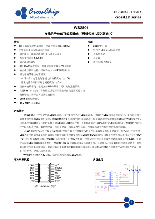
单位 V V V V mA
% MHz mW ℃/W
℃
V
最大 5.5 28 6 120 200 1 --1.5 --
±1
单位 V V V mA mA uA mA mA mA uS
uA
±20
uA
VDD
V
0.2*VDD V
0.624
V
0.2
V
--
%/V
--
%/V
--
KΩ
2
内部功能框图
DS-2801-SC rev0.1
3
典型应用电路
DS-2801-SC rev0.1
crossLED series
图3, WS2801 DC12V恒流典型应用电路
应用手册:
图4, WS2801 DC5V恒压典型应用电路
4
DS-2801-SC rev0.1
crossLED series
电压大于5V时候的应用: WS2801 的工作电源电压范围为 3.3~5.5V,芯片内部集成了 5.5V 稳压器以满足在高输入电压下芯片能够可靠工作。只需要在电
LED灰度控制信号在芯片内部经过时钟数据再生电路整形后在CKO和SDO端输出,以使芯片能够接力串接工作。当POL=
“0”时,输出极性反转,WS2801工作如同一个PWM控制器,能够驱动外接的开关或者电路驱动高亮度的LED,并实
现大功率LED的256级灰度控制。WS2801的2-线传输控制协议具有速度快,可靠性高,灰度数据同步刷新等特点,能够
I LED
其中RL是电流设定电阻,VDD是LED串的电源,VLED是LED串工作时的正向导通压降,VOUT是驱动输出的饱和压降,大概在0.1~0.2V, ILED是LED工作的工作电流,通常ILED≤20mA.
W28 二维指环扫描枪 产品规格书说明书

W28二维指环扫描枪产品规格书免责声明请您在使用本手册描述的产品前仔细阅读手册的所有内容,以保障产品的安全有效地使用。
阅读后请将本手册妥善保存以备下次使用时查询。
一旦使用本手册所述产品,即视为您已经仔细阅读免责声明与警告,理解、认可和接受本声明全部条款与内容,您承诺仅出于正当目的使用本产品,对使用本手册所述产品以及可能带来的后果承担相应的责任。
请勿自行拆卸本产品或撕毁产品上的封标,否则浩创科技不承担保修或更换产品的责任。
本手册中的图片仅供参考,如有个别图片与实际产品不符,请以实际产品为准。
本手册包含的所有信息和图片除特别标明之外,版权归浩创科技及其关联公司,未经书面许可,任何单位及个人不得以任何方式或理由对本手册全部或部分内容进行任何形式的摘抄、复制或与其它产品捆绑使用、销售。
本手册所述产品中可能包括浩创科技或第三方享有版权的软件,除非获得相关权利人的书面许可,否则任何单位或者个人不能以任何形式对前述软件进行复制、分发、修改、摘录、反编译、反汇编、解密、反向工程、出租、转让、分许可以及其它侵犯软件版权的行为。
本手册及产品所有相关的文档最终解释权和修改权归浩创科技,如有更新,恕不另行通知,请您访问官方网站或查阅最新版产品手册以获取最新的产品信息。
版本信息目录概述 (4)产品特点 (4)产品优势 (4)产品展示 (4)穿戴方式 (6)充电 (7)通过W2X/SC100充电座进行充电 (7)通过C20充电柜进行充电 (8)更换指环套 (8)指环套安装更换方法 (9)规格参数 (10)指示灯提示 (12)振动提示 (13)景深参数 (15)视场角度 (16)更新扫描枪固件 (17)包装明细 (18)电池安全指南 (19)附录 (20)功能设置条码 (20)通用设置 (20)换行符/制表符 (21)触发方式设置 (22)开启/关闭可识别码制 (23)可识别条码位数设置 (24)前导码输出开关设置 (29)附加码输出开关设置 (29)FULL ASCII开关设置 (30)蓝牙断开报警设置条码 (30)自动间隙出光扫描识别成功后的灭光时间设置 (31)概述除了商超柜台结账扫描目的是为了提取价格信息外,在快递、物流供应链、食品药品溯源管理、智能制造等领域的条码、二维码、RIFD扫描,都只是为了理清责任,起到作业环节转移时的电子签章功能。
WS2811规格书

时序波形图
输入码型:
数据传输方法:
WS2811
单线 256 级灰度三通道 恒流 LED 驱动 IC
连接方法:
注:其中 D1 为 MCU 端发送的数据,D2、D3、D4 为级联电路自动整形转发的数据。
24bit 数据结构:
R7 R6 R5 R4 R3 R2 R1 R0 G7 G6 G5 G4 G3 G2 G1 G0 B7 B6 B5 B4 B3 B2 B1 B0
0.5 µs
- 1、下载文档前请自行甄别文档内容的完整性,平台不提供额外的编辑、内容补充、找答案等附加服务。
- 2、"仅部分预览"的文档,不可在线预览部分如存在完整性等问题,可反馈申请退款(可完整预览的文档不适用该条件!)。
- 3、如文档侵犯您的权益,请联系客服反馈,我们会尽快为您处理(人工客服工作时间:9:00-18:30)。
LED 封装为硅胶,用力按压胶体表面会影响 LED 可靠性,因此应有预防措施避免在封装的零件上的强大压 力,当使用吸嘴时,胶体表面的压力应是恰当的。硅胶封装较柔软且有弹性,因它的特性大大减少了热应力,易 受机械外力损坏,因此在手工处理方面须要对硅胶封装材料做预防措施,若未按要求操作,可能会导致 LED 损 坏和光衰。
3/6
WS2815-Mini
智能外控集成 LED 光源 24bit 数据结构:
R7 R6 R5 R4 R3 R2 R1 R0 G7 G6 G5 G4 G3 G2 G1 G0 B7 B6 B5 B4 B3 B2 B1 B0
注:高位先发,按照 RGB 的顺序发送数据。
典型应用电路图:
1、推荐应用电路图:
5/6
WS2815-Mini
智能外控集成 LED 光源 3. 除湿处理
LED 产品超出以上规定期限,或者由于其他原因受潮,建议客户做除湿处理后再使用。 除湿方法:70℃-75℃/48±2 小时。
4. 静电防护
LED 是静电敏感器件,虽然 LED 产品具有优异的抗静电能力,但每经历一次静电释放产生的冲击, 都会对 LED 造成一定程度的损坏。因而在使用 LED 产品过程中需要做好静电防护措施, 例如佩戴防静电手套及防静 电手环等。
地线 辅数据输入
功能描述
PCB LAYOUT 时对地接一个滤波电容 电源供电脚,接 +12V 工作电源 控制数据信号输出脚 控制数据信号输入脚 信号接地和电源接地脚 辅助数据信号输入脚
最大额定值(如无特殊说明,TA=25℃,VSS=0V)
参数
电源电压 逻辑输入电压
工作温度 储存温度
符号
VDD VI Topt Tstg
范围
+9.5~+13.5 -0.5~VCC+0.5
-25~+85 -40~+105
单位
V V ℃ ℃
电气参数(如无特殊说明,TA=-20~+70℃,VDD=4.5~5.5V,VSS=0V)
参数
输入电流 高电平输入 低电平输入
滞后电压
符号
II VIH VIL VH
最小
—— 0.7VDD —— ——
典型
220ns~380ns 580ns~1.6µs 580ns~1.6µs 220ns~420ns 280µs 以上
连接方法:
D1
D2
D3
D4
DIN DO
DIN DO
DIN DO
PIX1
PIX2
PIX3
数据传输方法:
注:其中 D1 为 MCU 端发送的数据,D2、D3、D4 为级联电路自动整形转发的数据。
主要应用领域
● LED全彩发光字灯串,LED全彩软灯条硬灯条,LED护栏管。 ● LED点光源,LED像素屏,LED异形屏。
产品概述
WS2815-MINI是一个集控制电路与发光电路于一体的智能外控LED光源。其外型与一个3535LED灯珠相同, 每个元件即为一个像素点。像素点内部包含了智能数字接口数据锁存信号整形放大驱动电路、高精度的内部振 荡器和高精度恒流控制模块,有效保证了像素点光的颜色高度一致。实现双路信号传输,在单个像素点损坏的情 况下,不影响整体色彩的显示。
回流焊说明
1.回流焊不可以做两次以上 2.当回焊时,不要在材料受热时用力压胶体表面
烙铁焊接说明:
1.当手工焊接时,烙铁的温度必须小于 300℃,时间不可超过 3 秒 2.手工焊接只可焊接一次
修补说明:
LED 回流焊后不应该修补,当修复是不可避免时,必须使用双头烙铁 (如下图),但必须事先确认此种方 式会或不会损坏 LED 本身的特性。
液相温度(TL) 液相区保温时间(tL)
峰值温度(Tp) 高温区(峰值温度-5℃)停留时间(tp)
降温速率 室温至峰值温度停留时间
WS2815-Mini
智能外控集成 LED 光源
无铅回流焊 150℃ 200℃
60-180 S <3℃/S 217℃ 60-150 S 245℃ <10 S <6℃/S <6 min
下降时间
tTHZ —— —— 120
µs CL=300pF, OUTR/OUTG/OUTB
输入电容
CI —— —— 15
pF
——
2/6
LED 特性参数
静态电流 RGB 通道恒流 红光亮度(中心值) 绿光亮度(中心值) 蓝光亮度(中心值) 白光亮度(中心值) 红光波长 绿光波长 蓝光波长
数据传输时间
BIN端接收到数据信号吞噬24bit数据后,和DIN端数据比较,若DIN端无信号,BIN端有接收到信号,切换到 BIN端接收输入信号,确保其中一个IC的损坏不会影响信号的级联传输,控制IC保持在BIN端口接收状态,直到 断电后的下次开机重新确认。
高达 2KHZ的端口扫描频率,在高清摄像头的捕捉下都不会出现闪烁现象,非常适合高速移动产品的使用。 280us以上的 RESET时间,出现中断也不会引起误复位,可以支持更低频率,价格便宜的MCU。
运输及存储 1. 运输及适用范围 :
所有产品在运输过程中,需保持正面朝上,防潮防水,运输过程中逼免挤压、碰撞和剧烈震动。
2. 产品储存及期限 :
室温密封存储:20℃~30℃,40%~60%RH,产品有效期为 1 周; 防潮密封存储:20℃~30℃,25%~60%RH,产品有效期为 2 周; 产品拆包开封后,建议 2 小时内使用完成,(环境条件温度<30℃,湿度<60%)。
—— —— —— 0.35
最大
±1 —— 0.3 VDD ——
单位
µA V V V
测试条件
VI=VDD/VSS DIN, SET DIN, SET DIN, SET
开关特性(如无特殊说明,TA=-20~+70℃,VDD=4.5~5.5V,VSS=0V)
参数
符 最小 典型 最大 单位
号
测试条件
传输延迟时间 tPLZ —— —— 300 ns CL=15pF, DIN→DOUT, RL=10KΩ
数据协议采用单线归零码的通讯方式,像素点在上电复位以后,DIN端接受从控制器传输过来的数据,首先 送过来的24bit数据被第一个像素点提取后,送到像素点内部的数据锁存器,剩余的数据经过内部整形处理电路整 形放大后通过DO端口开始转发输出给下一个级联的像素点,每经过一个像素点的传输,信号减少24bit。像素点 采用自动整形转发技术,使得该像素点的级联个数不受信号传送的限制,仅仅受限信号传输速度要求。
WS2815-Mini
智能外控集成 LED 光源
主要特点
● 控制电路与RGB芯片集成在一个3535封装的元器件中,构成一个完整的外控像素点。 ● 12V供电电压,有效降低整个像素点的工作电流,降低线路板压降,最大限度
保证像素点在很远距离传输时达到良好的混光一致性。 ● 内置信号整形电路,任何一个像素点收到信号后经过波形整形再输出,保证线路波形畸变不会累加。 ● 每个像素点的三基色颜色可实现256级亮度显示,完成16777216种颜色的全真色彩显示。 ● 端口扫描频率2KHz/s。 ● 串行级联接口,能通过一根信号线完成数据的接收与解码。 ● 断点续传,额外增加一路信号线,实现双路信号传输,在单个像素点损坏的情况下,不影响整体显示效果 ● 任意两点传传输距离在不超过5米时无需增加任何电路。 ● 当刷新速率30帧/秒时,级联数不小于1024点。 ● 数据发送速度可达800Kbps。 ● 光的颜色高度一致,性价比高。
WS2815-Mini
智能外控集成 LED 光源
参考值 2.1mA 15mA 350mcd 1100mcd 200mcd 1650mcd 620-625nm 515-525nm 465-475nm
T0H T1H T0L T1L RES
时序波形图
输入码型:
0 码, 高电平时间 1 码, 高电平时间 0 码, 低电平时间 1 码, 低电平时间 帧单位,低电平时间
1. 通过使用适当的工具从材料侧面夹取
2. 不可直接用手或尖锐金属压胶体表面,它可能会损坏内部电路
3. 不可将模组材料堆积在一起,它可能会损坏内部电路
4.不可用在 PH<7 的酸性场所
6/6
机械尺寸(单位mm)
Top View
Back View
Side View
1/6
Solder Pad
引脚图:
WS2815-Mini
智能外控集成 LED 光源
引脚功能 :
序号
1 VDD DO DIN GND BIN
管脚名
IC 供电电源 LED 供电电源
主数据输出 主数据输入
注:C1 为 IC 旁路滤波电容。 2、由于 WS2815-Mini 内封电容,对于 PCB 走线比较复杂的线路,可以使用如下电路图,以节省布线空间:
无铅回流焊指引:
4/6
曲线说明 最低预热温度(Tsmin) 最高预热温度(Tsmax) 预热区时间(Tsmin to Tsmax)(ts) 平均升温速率(Tsmax to Tp)
