静电纺丝——Electrospinning
静电纺丝介绍

纤维直径下降(接收距离过近,溶剂挥发不完全,纤维扁平
环境参数
温度↑ 湿度 ↑ 空气流动↑ 纤维直径降低 在纤维表面形成多孔结构 加快溶剂挥发,可能形成多空纤维,同时使纤维直径上升
同轴静电纺丝
1.核-壳结构纤维 2.中空结构纤维:通常是具有核壳结构的纤维经过萃取或 者煅烧的过程来获得的。 PVP和钛酸异丙醇酯的乙醇溶液和矿物油分别作为内流 体和外流体,经过同轴静电纺丝和辛烷萃取除去芯层的矿 物油得到中空结构 Larsen以一种欲交联的无机物凝胶为壳层,不加入高分 子材料,以不混溶的橄榄油或甘油为芯层,然后高温除去 芯层的橄榄油或者甘油 Yu以合成好的纳米分子筛为骨架,PVP为粘结剂,液体 石蜡为内流体,制备了同时具有微孔,介孔,大孔的分子 筛
1.Mesoporous TiO2/SiO2 composite nanofibers with selective photocatalytic properties 2. LiCoO2–MgOcoaxialfibers:coelectrospunfabrication,characterization Andelectrochemicalproperties 3.利用同轴静电纺丝制备介孔TiO2中空纤维 4. Coaxial Electrospinning of Self-HealingCoatings Park和Braun利用同轴纺丝将具有自修复功能的聚 合物二甲基硅氧烷(polydimethylsiloxane)包裹在 PVP中,制备了具有自修复功能的纤维。 5. Electrospinning of nanofiberswith coresheath,hollow,orporousstructures
1 Coaxial Electrospinning
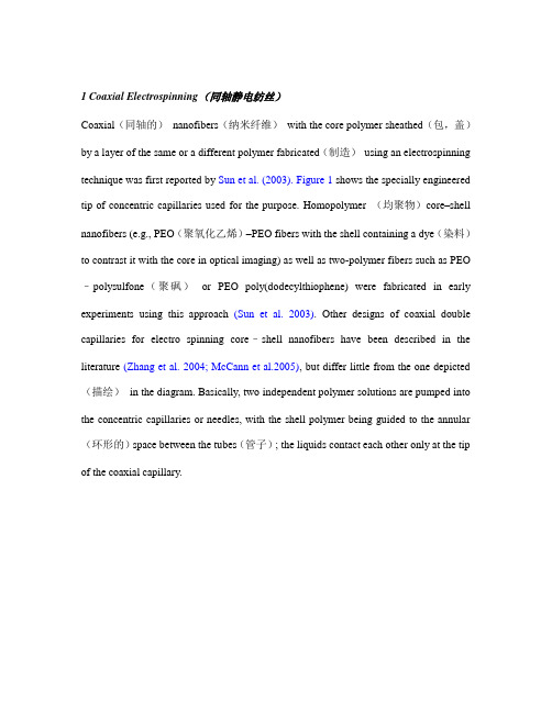
1 Coaxial Electrospinning(同轴静电纺丝)Coaxial(同轴的)nanofibers(纳米纤维)with the core polymer sheathed(包,盖)by a layer of the same or a different polymer fabricated(制造)using an electrospinning technique was first reported by Sun et al. (2003).Figure 1 shows the specially engineered tip of concentric capillaries used for the purpose. Homopolymer (均聚物)core–shell nanofibers (e.g., PEO(聚氧化乙烯)–PEO fibers with the shell containing a dye(染料)to contrast it with the core in optical imaging) as well as two-polymer fibers such as PEO –polysulfone(聚砜)or PEO poly(dodecylthiophene) were fabricated in early experiments using this approach (Sun et al. 2003). Other designs of coaxial double capillaries for electro spinning core–shell nanofibers have been described in the literature (Zhang et al. 2004; McCann et al.2005), but differ little from the one depicted (描绘)in the diagram. Basically, two independent polymer solutions are pumped into the concentric capillaries or needles, with the shell polymer being guided to the annular (环形的)space between the tubes(管子); the liquids contact each other only at the tip of the coaxial capillary.1 Figure 1 (a) The coaxial double-capillary tip arrangement used in electrospinning core–shell nanofibers. Reprinted with permission from Sun et al. (2003). Copyright 2003. John Wiley & Sons. (b) A coaxial tip design used by Larsen et al. (2003) forolive oil–water (liquid–liquid) coaxial jets. The inset shows the double-layered Taylor’s cone. Reprinted with permission from Larsen et al. (2003). Copyright 2003.American Chemical Society.The core-shell fiber morphology(形态)is initiated from the two-layered droplet (液滴)and the associated structured Taylor’s cone(圆锥体), produced using the coaxial capillary tip. A liquid jet(喷射)emerges simultaneously (同时)from the vertices (顶角)of the outer meniscus(弯液面)as well as from the inner core meniscus to yield a compound (混合物)jet of co-flowing solutions (Zhang et al. 2004). However, it is not necessary for both liquids to form stable jets for the process to work successfully, but at least one of these polymers needs to be electrospinnable. The ratio of core vs shell content in the compound fiber is controlled by changing the concentration of the polymer solutions or the relative feed rates used in spinning(纺丝). Figure 2shows the composition of a compound droplet formed from a coaxial tip, with a shell of PAN/DMF (12 wt% solution) and a core of PMMA(聚甲基丙烯酸甲酯)/acetone(丙酮):DMF (60:40) (15 wt% solution) (Zussman et al. 2006). The PMMA core can be pyrolized oroxidized(氧化)away to yield(产出)hollow nanofibers of PAN(聚丙烯晴). The characteristic time associated with mutual(相互的)diffusion(扩散)at the liquid–liquid boundary is much slower than the millisecond(毫秒)timescales (反应时间)associated with bending instability(不稳定性)and drying of the jet. For instance, in coaxial electrospinning of silk/PEO from the common aqueous(水成的,含水的)solvent(溶剂)(LiBr solutions) in which both polymers are miscible(可混合的), clear core–shell morphology was obtained in the nanofibers (Wang, H., et al. 2005). However, this need not be true of all systems. For example, McCann and colleagues reported that for the system of core (PS(聚苯乙烯)in DMF(二甲基甲酰胺)/THF(四氢呋喃)) and shell (PVP(聚乙烯基吡咯烷酮)/titanium isopropoxide(异丙氧化物)), the coaxially spun nanofibers lacked the characteristic core–shell morphology (McCann et al. 2005).Figure 2 (a) Composition of the compound Taylor’s Cone from a core–shell spinneret(喷丝头). (b) Hollow nanofibers formed by pyrolysis(热解)of the core–shell nanofibers.Reprinted with permission from Zussman et al. (2006). Copyright 2006. Wiley-VCH.With a pair of incompatible polymers such as PCL()聚己内酰胺and GT (both dissolved in 2,2,2-trifluoroethanol) (TFE(四氟乙烯)) (Zhang et al. 2004), mutualdiffusion during jet formation can be essentially ruled out. When core and shell polymers are dissolved in different solvents(溶剂)for coaxial spinning, however, these must be selected to avoid any possibility of precipitation(析出;沉淀)at the liquid–liquid interface(the solubility(溶解度)of the individual polymers in both solvents does not necessarily guarantee this). The use of immiscible(不互溶的)solvents in the core and shell generally contributes towards the stability of the jet. Critical physical properties of solutions that invariably determine the stability of coaxial jets are not well understood. Loscertales et al. (2004)found pairs of liquids that satisfied the condition Cσ>Sσto form stable structured cones (whereσis the liquid/dielectric(电介质)atmosphere surface tension and subscripts(注脚)c and s refer to core and shell liquids, respectively). Any instability of the jet may lead to the core being asymmetrically placed within the nanofiber (Jiang et al.2005). A bimodal(双模态)distribution or a mix of thick and thin fibers is sometimes obtained in coaxial spinning (Huang et al. 2006), with both types of fibers still showing the core/shell morphology. This suggests multiple (复合的)jets from a two-layered cone rather than the splitting or branching of the main jet during electrospinning.Interestingly, in the case of GT/PCL core/shell nanofibers , mechanical properties(力学性质)of the mat were found to be better than that of mats of individual components .In nanofibers that showed the best tensile(张力的)properties (electrospun with 7.5 w/v% GT solution and 10 w/v % PCL), the tensile strength(张力)and extensibility (延伸率)were 8.4 MPa and 178%, respectively. Comparable values for GT fibers were 5 MPa and 8%, while for PCL they were 1.3 MPa and 52%. A goodexplanation of this synergy (整合效果)is not available (Huang et al. 2006).A particularly interesting application of nanofibers with core–shell geometry is in tissue scaffolding(脚手架), where they perform the dual(双重的)role of mechanical support and the delivery of bioactive agents concurrently. Nanofibers with the water-soluble(可溶的)polymer PEG (聚乙二醇)used as the core and biodegradable (生物可降解的)PCL used as the shell polymer have been reported (Zhang et al. 2006c). A model agent (BSA conjugated(共轭)with fluorescein(荧光素)isothiocyanate(异硫氰酸盐; 异硫氰酸酯), ftc–BSA) was blended(混合)with the core polymer and electrospun using a coaxial capillary tip. A composite(合成物)blend of (ftc–BSA/PEG/PCL), blended in the same ratio of the constituents(成分)was also electrospun into blend nanofibers. Unlike with the core–shell fiber mat, the composite blend nanofibers were beaded and were of poor quality. Also, comparative BSA release studies showed the burst release phase to be suppressed only in core–shell nanofibers and that sustainability of the release was also superior for the same geometry relative to that in blend fibers.The coaxial electrospinning technique can be adapted to prepare hollow tubular (管状的)nanofibers (Loscertales et al. 2004)by using an easily extractible low molecular weight liquid as the core material. However, a shell polymer sheath(套), stiff(稠的)enough to avoid the collapse of the fiber after the removal of the core liquid by solvent extraction(拔出), needs to be used. Using a sol–gel precursor(前身,前体)material as the shell polymer is particularly useful in developing a stronger inorganic sheath material. The hollow nanofibers made with PVP blended with titanium isopropoxide (异丙氧化物)as the shell polymer and an oil as the core (Li and Xia 2004; McCann et al. 2005) and post-processed by calcinations(煅烧)illustrate this. Figure 3 shows TEM (投射电子显微镜)images of hollow nanofibers prepared in this manner. Core–shell nanofibers where the core material can undergo slow hydrolysis(水解)or biodegradation in a buffer(缓冲容器)can also yield hollow nanofibers. But in this case the core material is removed at a much slower rate that is determined by the thickness of the sheath. As with the case of nanofibers where the sheath layer is made of PCL and thecore is BSA-loaded PEG, the organic polymer shell (without reinforcement(强化)) tends to collapse into a flat fiber on removal of the core protein material (Jiang et al. 2005).Figure 3 (a) TEM image of a coaxially spun nanofiber with a shell layer of PEO and a core of poly(dodecylthiophene) (PDT). Both polymers were electrospun from CHCl3 (1–2% solutions). Reprinted with permission from Sun et al. (2003). Copyright 2003. John Wiley & Sons. (b) Hollow nanofibers of titania obtained by calcination of PVP (containing titanium isopropoxide) coaxially electrospun with an oil core. Reprinted with permission from Li and Xia (2004). Copyright 2004. American Chemical Society.In electrospinning regular nanofibers it is the concentration of polymer and the applied electric field that primarily determines average fiber diameters. The same must hold true for at least the shell polymer in electrospinning a core–shell nanofiber. An additional factor, however, is a “die–swell”effect where the viscoelastic(粘性的)core fiber swells(膨胀)against the wet shell material, increasing the fiber dimensions(尺寸). This was observed to occur with the core composition of fitc-BSA/PCL when spun with a PEG shell polymer. As the feed rate of the core polymer solution is increased, the average fiber diameters increased as well (Fig. 4). As the core material is not electrospinnable by itself, the swelling mechanism is likely to be responsible for this increase. Under the same experimental conditions, varying the feed rate of a nonviscoelastic(非粘性的)core material (hexane(己烷)) did not alter the fiber diameters (Song, T., et al. 2005).Coaxial spinning can also be used to form polymer–particle(微粒)composite nanofibers as discussed in Chapter 6. Li et al. (2005a), in their research on decorating the interior of hollow nanofibers with nanoparticles, used this technique very effectively. The core fluid used was a ferrofluid(铁磁流体)of magnetic iron oxide(氧化物)particles and the shell layer was a mixture of poly(vinyl pyrollidone)/titanium isopropoxide(异丙氧化物). Extraction of the core phase of the core–shell nanofibers with octane(辛烷)yielded hollow, magnetically susceptible(敏感的)nanofibers, with their interiors decorated with oxide nanoparticles.Figure 4 The effect of varying the feed rate of the core stream on the average fiber diameter of the core/shell nanofiber with a fitc–BSA/polycaprolactone core and a PEG shell. Reprinted with permission from Zhang et al. (2006c). Copyright 2006.American Chemical Society.2 Core–Shell Geometry by Post-Treatment of NanofibersCore–shell nanofibers can also be made by coating the exterior(.外面的)of an electrospun nanofiber with a polymer solution or other material. This is carried out eitherby gas-phase or solution deposition (dip coating) on the exterior of electrospun nanofibers.The TUFT(管形纤维模板)(tubes by fiber template(模板)) process (first described by Bognitzky et al. 2000)is an example of a gas-phase technique where a wall material or a conformal (保角;正形)coating is deposited(沉积)on the nanofiber surface and the core fiber is subsequently(其次)removed to yield a tubular(管状的)structure (Hou et al. 2002; Liu 2004). Mild coating conditions allows thin (as thin as 50 nm) conformal defect(缺陷)-free coatings to be applied in this manner without causing any thermooxidative degradation of nanofibers in the process(Hou et al. 2002). Protein delivery characteristics of PV A nanofibers were shown to be modified by applying a thin coating of poly(p-xylylene) (PPX), as already pointed out in Chapter 7(Zeng et al. 2005a). Bognitzki et al. (2000)electrospun PLA nanofibers (d=300–3500 nm) from CH2Cl2 solutions and deposited a layer of PPX on the nanofiber surface by chemical vapor (蒸汽)deposition (CVD). This was converted into a hollow fiber by pyrolytic removal of the PLA core material at 2508C. Hollow tubular nanofibers with a thin metal coating (of Al or Au) either on the outside or the inner walls of fiber were obtained by combining this approach with physical vapor deposition. The TUFT approach was used by Ochanda and Jones (2005) to create metal shell nanofibers. A thin metallic shell of Au, Cu, or Ni was then deposited on the fiber by electroless plating with solutions of the metal salt and a reducing agent. On pyrolysis, the shell of the core–shell nanofibers was converted into metal nanotubes (d =450-730 nm) with a wall thickness of 50-150 nm. The metal was in polycrystalline(多晶的)form with a particle size in the range of 5-25 nm. Other related coating methods such as physical vapor deposition (PVD; Wei et al. 2006a; Liu et al. 2002), plasma-enhanced PVD (PEPVD; Buldum et al. 2005), initiated CVD (aluminum coating on poly(m-phenylene isophthalimide) nanofibers; Liu et al. 2002) have been used to deposit thin coating layers of metal on the nanofibers. Initiated CVD has been used to render(反映)PCL nanofibers more hydrophobic(疏水的)by coating them with a polymerized perfluoroalkyl(全氟烃基)ethyl methacrylate(异丁烯酸)layer (Ma, M. L., et al. 2005b). To ensure that coatings adhere(粘附)well, nanofiber surfaces may be plasma(等离子体)treated prior to coating as in the case of P(LLA-CA 70 : 30) copolymer(共聚物)nanofibers coated by chitosan(甲壳质)(He et al. 2005).Simple dip coating has also been used with nanofibers. For example, electrospun PLA nanofiber mats were coated with a 1–4% solution of polyamic acid followed by heat treatment at 150–285o C to convert the coating into a polyimide(聚酰亚胺)(Bognitzki et al. 2000). Dip coating has also successfully been used to convert an organic nanofiber into a hollow inorganic nanofiber. PLLA nanofibers electrospun from CH2Cl2solutionswere soaked first in a metal oxide precursor solution of titanium isopropoxide and then in isopropanol(异丙醇)/water solutions to convert the alkoxide(醇化物)into titania. The core PLLA was removed by calcination to obtain hollow titania nanofiber(Caruso et al. 2001). Others have combined physical coating from solution with electrostatic layer-by-layer (LBL) deposition (Ding et al. 2005b)to construct multilayer core–shell fibers of poly (acrylic acid) (PAA)/titania layers for sensor applications. The layer-by-layer technique was also used to deposit a layer of fluorescent probe molecules onto the surface of electrospun cellulose(纤维素)acetate(乙酸盐;乙酸基)nanofibers. These nanofibers were shown to be effective in detecting ppb levels of methyl viologen and cytochrome(细胞色素)C in aqueous solution (Wang, X. Y., et al. 2004). Coating ionically functionalized nanofibers in liquid phase is particularly facile(容易的)because of the electrostatic interactions(Drew et al. 2005).Dip coating while simple and cost effective does not always lead to a continuous uniform shell layer as obtained in coaxial electrospinning. A comparison of the relative effectiveness of collagen/PCL core-shell nanofiber mats and collagen-coated PCL nanofiber mats as scaffolding for human dermal(皮肤的)fibroblasts (HDF) was carried out by Y. Z. Zhang et al. (2005c). The results showed significantly reduced density of cells attachment on the dip-coated nanofiber mat relative to that on core-shell nanofibers.。
静电纺丝技术
静电纺丝技术的研究摘要:文章介绍了静电纺丝制备纳米纤维的技术,详细地介绍了这种技术的优点,以及它在各个方面广泛的应用。
此外,虽然它具有很多的优点,但目前也仍然存在一些问题,我们也对此进行了探讨。
关键词:静电纺丝纳米纤维应用原理前言:近年来,纳米结构材料,如纳米纤维、纳米管,由于其尺寸效应十分显著,在光、热、磁、电等方面的性质和体材料明显不同,出现许多新奇特性,因此收到了研究人员的高度重视。
纳米纤维最大的特点就是比表面积大,从而导致其表面能和活性的增大,产生小尺寸效应、表面或界面效应、量子尺寸效应、宏观量子隧道效应等,在化学、物理性质方面表现出特异性[1]。
电纺技术是一种简单和通用的获得连续微米级别以下的超细纤维的方法。
通过电纺的方法可以制备出多种纳米纤维,包括氧化物纤维,高子分聚合物纤维等。
静电纺丝方法制备的纳米纤维,具有纳米尺寸的直径,高比表面以及纤维之间形成的微小孔隙[2]。
纳米纤维、静电纺丝都是一些新事物,具有广阔的发展前景。
可以用于组织工程、人造器官、药物传递和创伤修复等。
另外,对植物施用杀虫剂是纳米纤维可能大规模应用的又一个领域。
但当前的静电纺丝技术还不成熟,有待于深入地研究,以制得高质量的纤维并能使纳米纤维的制备实现产业化[3]。
一静电电纺丝技术静电纺丝技术(electrospinning)在国内一般简称为电纺,其是一种利用聚合物流体在强电场作用下,通过金属喷嘴进行喷射拉伸而获得直径为数十纳米到数微米的纳米级纤维的纺丝技术。
通过静电纺丝技术得到的纳米级纤维具有直径小、表面积大、孔隙率高、精细程度一致等特点,在组织工程、传感器、工业、国防、农业工程等领域具有极大的发展潜力,而且其在医药领域诸如伤口敷料、控制释放体系等方面也有着巨大的应用前景[5]。
从科学基础来看,这一发明可视为静电雾化技术的一种特例。
静电雾化与静电纺丝的最大区别在于:两者所使用的工作介质不同。
静电雾化采用的是粘度较低的牛顿流体;而静电纺丝采用的是粘度较高的非牛顿流体。
静电纺丝与纳米纤维
摘要纳米纤维是一种新型的纤维材料,其优异的性能,潜在的用途引起了各个领域的重视。
静电纺丝作为一种生产纳米纤维的方法,有着简单,低成本,纤维形貌可控等特点。
本文将对纳米纤维与静电纺丝的发展历史,通过控制纳米纺丝工艺参数制造形貌可控的纤维进行阐述,并对静电纺丝法制备纳米纤维进行展望。
关键词:静电纺丝,纳米纤维,形貌,工艺参数1 绪论1.1 纳米纤维简介从古至今,人类从未停止对微观世界的探索。
光学显微镜的发明使我们可以观察次微米级的物质特征;1906年,英国物理学家汤姆逊发现电子,并提出原子的枣糕模型;1919年,卢瑟福用α粒子轰击氮核,第一次实现了原子核的人工转变,并发现了质子。
预言原子核内还有另一种粒子,被其学生查德威克于1932年在α粒子轰击铍核时发现,由此人们认识到原子核由质子和中子组成。
1933年,德国人发明第一台电子显微镜,人类开始可以对纳米级微观世界进行直接的观察。
纳米技术由此孕育而生。
纳米技术是一门前沿交叉学科,其涉及物理,化学,生物等各个学科,在纳米尺度上研究物质的结构性能与制备。
有人预言,纳米技术将成为21世纪的主导,将带来一大批产业革命,其意义不亚于近现代的三次工业革命[1]。
通常人们将长度比直径大千倍以上且具有一定柔韧性和强力的纤细物质统称为纤维。
纤维广泛存在于我们生活的各个角落,例如我们穿的衣物。
最初的纤维主要来源于自然界,例如棉,麻等植物纤维以及动物毛发等动物纤维。
随着科技的发展,人类逐渐掌握了合成纤维的制备技术。
合成纤维的化学组成和天然纤维完全不同,是从一些本身并不含有纤维素或蛋白质的物质如石油、煤、天然气、石灰石或农副产品,用化学合成与机械加工的方法制成纤维。
如聚酯纤维(涤纶)、聚酰胺纤维(锦纶或尼龙)、聚乙烯醇纤维(维纶)、聚丙烯腈纤维(腈纶)、聚丙烯纤维(丙纶)、聚氯乙烯纤维(氯纶)等。
由于日常生产生活对纤维的性能要求越来越高,纤维的制造技术就成了纺织和化工工业关注的重点[2]。
静电纺丝

设计了一套装 置,可以制备 直径在0.051.1微米的丙烯 酸纤维。考察 了纤维直径与 溶液黏度、射 流长度及环境 气体组分之间 的关系。
将聚乙烯和 聚丙烯熔体 纺成连续的 纤维,研究 发现,直径 取决于电场, 操作温度和 熔融体粘度, 与喷丝嘴直 径无明显关 系。
基本设备
静电纺丝的基本设备包括:高压电源、喷丝头和接收装置。纺丝液通 过注射泵从喷丝头中挤出形成小滴,小滴在高压电作用下变成锥形, 在超过某一临界电压后进一步激发形成射流,射流在空气中急剧震荡 和鞭动,从而拉伸细化,最终沉降在接收装置上。
熔体静电纺丝具有溶液静电纺丝无法比拟的优点: 1、不需要有机溶剂,成本低、生产效率高; 2、适用于一些室温下没有合适溶剂的聚合物,如PP、PE等; 3、对熔体电纺建模,有助于更加深入了解电纺机理; 4、如能与现有的熔喷装置相结合,则有很强的工业化应用前景。 同时也存在一定的问题: 1、聚合物熔体粘度高、导电性差,需要较高的电场强度,易发生电场击穿的危险。 2、制备的纤维多在微米级别; 3、装置复杂,需附加高温加热装置,易和高压装置发生静电干扰。
高压静电纺丝的基本过程
静电纺丝的过程可以简单的描述如下:首先在喷丝口处溶液被拉出表面, 沿着直线运动,当运动到一定位置,进入非稳定阶段,开始成螺旋摆动运动,同 时喷射流被进一步拉伸细化。 1、喷射流初始运动阶段 2、喷射流摆动非稳定阶段 在电场力的作用下,喷丝口处的溶液表面布满阳离子或分子中的缺电子 部分,当外加电压较小时,电场力不足以使溶液喷出,喷丝口处的溶液形成 “泰勒锥”,加大电压,当其超过特定的临界值时,带点锥体形成一股带点的 喷射流,沿电场方向加速运动。经过一段稳定的直线运动后,纤维开始不规则 摆动,在接收装置上的落点随机,这一过程中纤维表现出的状态即为非稳定性。
静电纺丝及其应用 中文
静电纺丝技术以及静电纺丝纳米纤维在不同领域的应用本文内容主要参考了夏幼南教授的一篇综述文章[1],本人只是自己语言重新组织了一下他的文章内容,并在此基础上加入了一些个人的理解。
基于上述原因,在此向夏幼南老师表示特别感谢。
1. 纳米静电纺丝技术发展的历史静电纺丝技术又简称静电纺丝或者电纺丝,其发展历史最早可以追溯到1600年,William Gilbert 在存在外部电场的情况下观察到了一个锥形水滴[2]。
随后在1887年,Charles Boys 利用一种粘弹性的液体通过静电纺丝制备出了纳米纤维[1]。
1938年,静电纺丝纳米纤维被用于制造空气过滤装置的过滤网芯,静电纺丝纳米纤维首次得到了应用[1]。
从1938年至今,静电纺丝技术不断发展并逐渐走向成熟,如今已经被应用在了各个领域,极大的推动了科学研究和工业生产的进步与发展[3,4]。
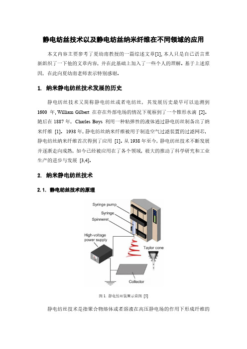
2. 纳米静电纺丝技术2.1. 静电纺丝技术的原理图1. 静电纺丝装置示意图[5]静电纺丝技术是指聚合物熔体或者溶液在高压静电场的作用下形成纤维的过程。
静电纺丝技术装置主要由三部分组成,分别是高压电源,喷丝头以及接收板(图1.)。
其中电源可以是直流电源,也可以是交流电源,不同类型的电源对纳米纤维的形成有一定的影响,这里不再详细介绍。
喷丝头可以使用带有注射器针头的塑料管、金属管及玻璃管等,喷丝嘴一般为0.1~1 mm。
接收板用来接收经溶剂挥发或者熔体固化后所形成的聚合物,一般采用导电金属板、硅片及导电玻璃等。
具体使用过程中,金属板表面要用锡纸、纺布等包裹起来,方便转移纳米纺丝并防止接收板被污染或者被弄脏[6]。
电源的两极分别接在喷丝头和接收器上,在高压静电纺丝的过程中,溶液或者熔融高分子表面带上了电荷并产生了电场力,溶液的表面张力与电场力方向相反。
随着电压的增大,电场力大于表面张力时,带电溶液从喷丝口喷出,从而形成喷流。
喷流在空气中运动的过程中,经溶剂挥发,降温冷却等过程逐渐固化,最后被收集于接收器上。
聚合物TiO2杂化电纺微纳米纤维制备【开题报告】

毕业设计开题报告纺织工程聚合物/TiO2杂化电纺微纳米纤维制备一、选题的背景、意义电纺丝(Electrospinning)是一种利用聚合物溶液或熔体在强电场中的喷射作用进行纺丝加工的工艺。
近年来,电纺丝作为一种可制备超细纤维的新型加工方法,引起了广泛的关注。
由电纺丝加工得到的纤维产品称为电纺纤维(Electrospun fiber)。
其最大的特点是直径范围一般在3n m-5um,比常规方法制得的纤维直径小几个数量级。
电纺纤维无纺布孔隙率高、比表面积大、纤维精细程度与均一性高、长径比大,在功能材料领域有着广阔的应用前景。
目前,在纳米复合材料、传感器、伤口敷料、膜分离以及组织工程等领域,电纺纤维都得到了广泛的应用。
目前国外对电纺丝的研究发展迅速,成果也非常多.而国内的相关研究正处于起步阶段。
电纺丝技术是目前制备纳米纤维最重要的基本方法,以聚乙烯醇PV A为基体,以水为溶剂,采用静电纺丝技术首次制得TiO2:纳米纤维材料。
史铁钧等用溶胶、凝胶法制备了不同二氧化硅含量的PV A/SiO2:杂化电纺纤维膜,并分析了纤维膜结构形态的形成机理。
用溶胶一凝胶法和电纺法制备了PV A/SiO2:TiO2:杂化电纺纤维膜,并对其形貌、结构与性能进行了研究,探讨了不同反应条件对电纺纤维分散形态和尺寸的影响,并对其稳定性和耐水性进行研究。
20世纪90年代后期,科学家们对于纳米纤维制备及应用的研究达到高潮,开发了一系列制备聚合物纳米纤维的方法,如纺丝、模板合成法、相分离法、自组装法以及静电纺丝法等。
与上述方法相比,静电纺制备聚合物纳米纤维具有设备简单、操作容易以及高效等特点,因此它被认为是制备聚合物连续纳米纤维最有效的方法。
而静电纺丝理论研究对于深入研究静电纺丝过程具有重要意义。
二、相关研究的最新成果及动态1. 静电纺丝的发展历程[ 7 ]1966年,Simons[22]申请了由静电纺丝法制备超薄、超轻无纺布织物的专利。
electrospinning

电纺
前驱体纤维
热处理
A
前驱体纤维
B
ZnO纳米纤ZnO纤维(HRTEM)
氧化锌纳米纤维的电纺丝制备. (A) PVA/ZnAc2复合纤维,以及氧化 锌纳米线的(B)扫描电镜;(C)透射电镜;(D)高分辨透射电镜照片
电纺丝制备功能陶瓷纳米纤维
* *
Intensity (a.u.)
取向的PVA/ZnAc2纳米线(左图)和氧 化锌纳米线(右图)
电纺丝纳米线组装晶体管
电纺丝法组装的纳米线晶体管结构示意图
电纺丝纳米线组装晶体管
电纺丝法制备和组 装的CuO纳米线晶 体管(左上图)及 其电学性能。
电纺丝纳米线组装晶体管
电纺丝法制备和组 装的ZnO纳米线场 效应晶体管(左上 图)及其电学性能。 该器件可望被作为 基本元件被用于纳 米电子器件,并可 望被应用于气敏传 感器和紫外光敏感 元器件。
均匀、连续的氧化铜、氧化镍、氧化铁及氧化铝掺杂氧化锌纳米线同样可以 通过电纺丝法制备。
Fe2O3 纳米线
Al2O3-ZnO 纳米线
电纺丝制备金属纳米纤维
电纺丝制备金属纳米纤维
过渡金属纳米线可以通过对电纺丝氧化 物纳米纤维的还原反应制备。
CuO + H2 NiO + H2
Fe2O3 + 3H2
H2O + Cu H2O + Ni
电纺丝制备的铁纳米纤维
电纺丝制备金属纳米纤维
电纺丝制备的银、NiO复合纳米纤维
NiO Ag
电纺丝组装和排列纳米纤维
电纺丝组装纳米纤维
通过对接受装置的改装, 电纺丝法可以方便的收集 到取向的纳米纤维阵列。
电纺丝纳米纤维的应用
电纺丝组装纳米纤维
通过改装纺丝设备,减小收集装置与喷射 针头的距离,可以在针头与接受板之间收 集到取向的纳米线阵列。
静电纺丝

静电纺丝技术的应用及其发展前景材料成型09-3 陈桂宏 14095543“静电纺丝”一词来源于“electrospinning”或更早一些的“electrostaticspinning”,国内一般简称为“静电纺”、“电纺”等等。
早在上世纪30年代就有人在电纺技术上申请了一系列的专利,是人们早已知晓的一项技术。
1934年,Formalas发明了用静电力制备聚合物纤维的实验装置并申请了专利,其专利公布了聚合物溶液如何在电极间形成射流,这是首次详细描述利用高压静电来制备纤维装置的专利,被公认为是静电纺丝技术制备纤维的开端。
但是,由于静电纺丝的可生产性较低,并没有引起人们的注意,直到近十年,由纳米技术的迅速发展,静电纺丝才再次引起世界各国研究学者的关注,并逐渐成为世界上用得到的最普遍生产纳米纤维的方法。
通过静电纺丝技术制备纳米纤维材料是近十几年来世界材料科学技术领域的最重要的学术与技术活动之一。
静电纺丝以其制造装置简单、纺丝成本低廉、可纺物质种类繁多、工艺可控等优点,已成为有效制备纳米纤维材料的主要途径之一。
图 1 静电纺丝装置图1 静电纺丝技术原理及影响因素静电纺丝的基本原理是:聚合物溶液或熔体在高压静电的作用下,会在喷丝口处形成 Taylor锥,当电场强度达到一个临界值时,电场力就能克服液体的表面张力, 在喷丝口处形成一股带电的喷射流。
喷射过程中, 由于喷射流的表面积急速增大, 溶剂挥发, 纤维固化并无序状排列于收集装置上 ,从而得到我们需要的纳米纤维, 其装置图如图 1 所示。
电纺技术制备的纤维直径可以在数十纳米到数百纳米之间。
到目前为止, 已经报道有大约 100种聚合物利用静电纺丝技术制备出超细纳米纤维。
静电纺丝法的许多工艺参数相互密切联系,决定了纤维的直径大小和纤维的均匀性等性质。
影响静电纺丝过程的因素主要有两个方面, 一是溶液的性质,包括溶液粘度, 表面张力等; 二是电纺设备参数, 如外加电压, 收集装置之间的距离等。
静电纺丝技术的工艺原理及应用

静电纺丝技术的工艺原理及应用静电纺丝技术是目前制备纳米纤维最重要的基本方法。
这一技术的核心是使带电荷流体在静电场中流动与变形,最终得到纤维状物质,从而为高分子成为纳米功能材料提供了一种新的加工方法。
由于纳米纤维具有许多特性,例如纤维纤度细、比表面积大、孔隙率高,因而具有广泛的应用。
1、静电纺技术静电纺是一项简单方便、廉价而且对环境无污染的纺丝技术。
早在20世纪30年代,Formals A就已经在其专利中报道了利用高压静电纺丝,但是直到近些年,由于对纳米科技研究的迅速升温,激起了人们对这种可制备纳米尺寸纤维的纺丝技术进行深入研究的浓厚兴趣。
1.1 静电纺技术的基本原理静电纺丝技术(Electrospinning fiber technique)是使带电的高分子溶液(或熔体)在静电场中流动变形,经溶剂蒸发或熔体冷却而固化,从而得到纤维状物质的一种方法。
对聚合物纤维电纺过程的图式说明见图1。
静电纺丝机的基本组成主要有3个部分:静电高压电源、液体供给装置、纤维收集装置。
静电高压电源根据电流变换方式可以分成DC/DC和AC/DC两种类型,实验中多用IX;/DC电源。
液体供给装置是一端带有毛细管的容器(如注射器),其中盛有高分子溶液或熔体,将一金属线的一端伸进容器中,使液体与高压电发生器的正极相连。
纤维收集装置是在毛细管相对端设置的技术收集板,可以是金属类平面(如锡纸)或者是旋转的滚轮等。
收集板用导线接地,作为负极,并与高压电源负极相连。
另外随着对实验要求的提高,液体流量控制系统也被渐渐的采用,这样可以将液体的流速控制得更准确。
电场的大小与毛细管口聚合物溶液的表面张力有关。
由于电场的作用,聚合物溶液表面会产生电荷。
电荷相互排斥和相反电荷电极对表面电荷的压缩,均会直接产生一种与表面张力相反的力。
当电场强度增加时,毛细管口的流体半球表面会被拉成锥形,称为Taylor锥。
进一步增加电场强度,是用来克服表面张力的静电排斥力到达一个临界值,此时带电射流从Taylor锥尖喷射出来。
静电纺丝制备纳米纤维的研究进展

静电纺丝制备纳米纤维的研究进展鲍桂磊;张军平;赵雯;朱娟娟;王改娥【摘要】Due to tiny diameter, big specific surface area, and the ability to achieve surface functionalization easily, nanofibers are attracting great attention, and electrospinning technology is considered to be the most simplest and effective way to prepare polymer nanofibers, many researchers at home and abroad have studied the electrospinning technology in detail. In this paper, the working principle of electrospinning was introduced briefly, and influential factors on the electrospinning process were analyzed, such as solvent, consistency and viscosity, conductance, applied voltage, flow rate and distence between the gaps. In addition, application of electrospun nanofibers in the fields of filter media material, sensors and biomedical engineering was described, and some problems of this technique were pointed out as well as countermeasures.%纳米纤维具有直径小、比表面积大和易于实现表面功能化等优点,受到了广泛的关注,而静电纺丝技术被认为是制备聚合物纳米纤维最简单有效的方法,因此国内外学者对静电纺丝技术进行了详细的研究。
静电纺丝

2、针头体系。 1)单针头 单针头最常见,根据需要可选择不同型号的针头。
9
2)同轴针头 同轴电纺的一个优点在于可以突破单头体系的限制,将一些难以直接电 纺的聚合物通过同轴电纺装置制备纳米纤维。另一个优势是通过将核层选择性 移除,还可以制备中空纳米纤维结构。
10
3)并列式针头
并列式针头体系是一 种结构简单却易于实现功能 化纳米纤维制备的喷丝头体 系。它将不同的聚合物溶液 通过紧密靠在一起的并列式 针头同时进行射流激发,在 电纺过程中平行射流融合, 得到多根纤维互相连接的束 状单根纤维,因此特别适合 制备双组份聚合物纤维。
• 泰勒锥:在外加电场的作用下 ,聚集在喷丝口的聚合物溶液 液滴的形状会变成锥形,称为 “泰勒锥”。随着电场力的增 加,“泰勒锥”逐渐变尖,当 锥顶角到达一个临界值后, Taylor计算出临界角的大小为 49.3°,液滴的相对稳定状态 被破坏,锥顶表面分子受到足 够大的电场力来克服表面张力 ,高分子溶液从锥顶喷射出来 ,形成一股喷射流。
R c(I / Q)2/3 r1/3 20
基本原理
• 总的来说:当外加电场开始作用于毛细管顶端,流体表面产生大 量静电电荷。毛细管顶端液滴的表面张力受静电斥力削弱,被逐 渐拉长形成带电锥体,即泰勒锥当电场强度增大到特定临界值时 ,流体表面的电荷斥力大于表面张力,带电流体就会从泰勒锥的 顶点喷射出来,形成带电射流。在喷射区带电射流将经历一个突 然加速的过程,同时聚合物因溶剂挥发凝结或熔融体冷却固化形 成聚合物纤维形成,并被高度拉伸而逐渐细化,最后沉积在接地
28
将聚偏氟乙烯(PVDF)静电纺丝纳米纤维薄膜应用在固液分离领域,证明 了其去除颗粒的适用性。经过表征发现,PVDF静电纺丝纤维薄膜与传统的微滤 膜具有相似的性质。这种膜被用于分离1μm、5μm、10μm的聚苯乙烯颗粒。实 验结果表明此纤维膜能除去溶液中90%的微米颗粒。
静电纺丝与纳米纤维
LOGO
1 2 3 4
年研究发现,阐述了一种利用静电力生产聚合物细丝的装置,其主要原理是利用高压静电场激发聚合物的带电射流,使射流固化得到聚合
v纳米纤维nanofiber
纳米纤维指的是直径从几十纳米到1μm的纤维。
在学术上界定<100nm为纳米级,但是由于商业上的灵活性,纤维直径为300nm甚至是>500nm这个在学术界一般归为次微米级的尺度范围,也将其称为纳米纤维。
A B
静电纺丝装置主要由毛
(器)、聚
和高压电
Taylor锥
力等
应用
用,是医用支架、结构稳
长药效、细纤维具有直径小、
溶解和提
物的快释、
避免药物初
对于提高着很好的力。
纳米器和生物
高的过滤精
过滤材料
过滤介质使用纳米尺寸的纤维。
静电
在环境污染网的性能优法不用去除
LOGO。
静电纺丝文献综述
学号:北京化工大学毕业设计开题报告题目:学院:材料科学与工程学院专业:班级:姓名:指导教师:专业负责人:指导老师意见:指导老师签字:日期: 年月日日期:年月日静电纺丝文献综述摘要:静电纺丝技术自从2000年以后进入快速发展期,论文和专利都成指数型增长。
目前,研究的现状从这些研究的内容看,研究主要围绕静电纺丝的应用、工业化、原理三个方面。
同时,在医用材料领域,静电纺丝也逐步展开了研究。
关键词:静电纺丝,研究现状,医用材料Abstract:Electrospinning develops rapidly that papers and patents increase exponentially since 2000. The research status focus on applications, industrialization and principle. Meanwhile, electrospinning research on biomaterials is springing up.Key words: electrospinning, research status, biomaterials application1 静电纺丝发展目前常用的制备纤维的方法有拉伸法、模板法、相分离法和静电纺丝法。
其中,静电纺丝法制备纤维因其操作简单、适用较广和成本低而广泛被使用在纺丝领域。
静电纺丝是A.Formhals在1934年发明[1]。
在1938年至1944年期间,随着A.Formhals 对静电纺丝技术的进一步改进和对静电纺丝原理的探究[2-7],静电纺丝技术得到了进一步的发展。
1969年,Taylor发现了Taylor锥[8],对静电纺丝的原理进行了进一步的丰富。
1971年,杜邦公司利用静电纺丝制备了PAN亚纳米纤维。
1981年,美国Ethicon 公司研究了静电纺丝技术在医学领域的应用[9]。
静电纺丝

摘要纳米纤维由于具有极小的直径以及极大比表面积和表面积~体积比的结构特点,其表面能和活性增大,从而在化学、物理(热、光、电磁等)等许多性能方面表现出特异性,可用于高性能吸附、过滤、防护、生物医用等材料。
聚合物纳米纤维的制备方法有静电纺丝法、复合纺丝法、分子喷丝板法、生物合成法、化学合成法等,静电纺丝是一种高效低耗的聚合物纳米纤维制备方法,是目前研究的热点,而且具有较大的发展前景。
静电纺丝是基于高压静电场下导电流体产生高速喷射的原理发展而来,其基本过程是:聚合物溶液或熔体在几千至几万伏的高压静电场下克服表面张力而产生带电喷射流,溶液或熔体射流在喷射过程中干燥,并保持一定电荷量,最终落在接收极上形成纤维。
静电纺丝制得的纤维直径一般在数十纳米到数微米之间。
静电纺的纤维制品主要呈无纺布状纤维毡的形式,静电纺纤维毡具有很高的比表面积和表面积体积比,以及良好的力学性能,在生物医学、过滤材料和复合材料等方面有广阔的应用前景。
聚乙烯醇(PV A)纤维大分子中含有大量的羟基,—OH中的氧原子含有孤对电子,可以进入金属离子空的价电子轨道,金属离子与PV A配位体通过杂化轨道形成配位键,进而形成金属配合纤维。
本文选用静电纺丝法制备的PV A纳米纤维毡为基体,与金属铜离子发生配位反应,制备PV A基金属配合纳米纤维.实验中通过静电纺丝法制备不同浓度的PV A纳米纤维膜,采用扫描电子显微镜(SEM)观察电纺纤维的微观形貌,利用旋转式粘度仪、数显电导率仪与液滴性状分析仪对PV A纺丝液的流变性能进行研究,采用原子吸收光谱分析仪研究PV A 纳米纤维膜吸附的金属离子含量,采用红外光谱(FT-IR)分析了PV A与金属离子的配合作用。
同时也测定了PV A及其金属离子配合纤维的动态接触角和力学性能,以研究金属配合对纳米纤维导电性、亲水性和力学性能的影响。
实验结果表明,PV A浓度为10%的静电纺纳米纤维最佳;PV A纳米纤维与金属离子配合的能力较常规PV A纤维有显著提高。
国内外静电纺丝技术的研究进展

国内外静电纺丝技术的研究进展郝明磊;郭建生【摘要】静电纺丝技术是目前为止获取纳米纤维最简单有效的方法之一,但产量低一直是限制其大规模运用的瓶颈。
近几年世界上出现了大量与此相关的研究,比如通过设计多针头静电纺和无针头静电纺装置,在一定程度上提高了静电纺丝的产率,但仍有很多问题亟待解决。
本文主要介绍了静电纺丝技术的发展进程及面临的问题。
%Electrospinning is the one of the simplest and effective methods for producing nanofibers at present. However, low production capacity has been the bottleneck for its large-scale application. Over the past few years, there have been lots of relevant researches on electrospinning, and many researchers designed multi-needle device and single-needle device to improve its productivity, but there are still many problems to be resolved. This article discussed the research progress and esisting problems of electrospinning technology in detail.【期刊名称】《纺织导报》【年(卷),期】2013(000)001【总页数】3页(P58-60)【关键词】静电纺丝;纳米纤维;技术进展【作者】郝明磊;郭建生【作者单位】东华大学纺织学院;东华大学纺织学院【正文语种】中文【中图分类】TQ340.65纳米纤维严格意义上是指纤维直径小于100 nm的超微细纤维。
静电纺丝

静电纺丝1原理静电纺丝是一种特殊的纤维制造工艺,聚合物溶液或熔体在强电场中进行喷射纺丝。
在电场作用下,针头处的液滴会由球形变为圆锥形(即“泰勒锥”),并从圆锥尖端延展得到纤维细丝。
这种方式可以生产出纳米级直径的聚合物细丝。
2静电纺丝影响因素1,聚合物的分子量,分子量分布和分子结构(分支,线性等)2,溶液性质(浓度,粘度,电导率,表面张力,液体流量等)3,电动势大小4,毛细管和收集屏幕之间的距离5,环境参数(温度,湿度和室内空气流速)6,收集装置的运动规律7,喷丝口针头形状3静电纺丝技术的发展静电纺丝技术的起源“静电纺丝”一词来源于“electrospinning”或更早一些的“electrostatic spinning”,国内一般简称为“静电纺”、“电纺”等。
1934年,Formalas发明了用静电力制备聚合物纤维的实验装置并申请了专利,其专利公布了聚合物溶液如何在电极间形成射流,这是首次详细描述利用高压静电来制备纤维装置的专利,被公认为是静电纺丝技术制备纤维的开端。
但是,从科学基础来看,这一发明可视为静电雾化或电喷的一种特例,其概念可以追溯到1745年。
静电雾化与静电纺丝的最大区别在于二者采用的工作介质不同,静电雾化采用的是低粘度的牛顿流体,而静电纺丝采用的是较高粘度的非牛顿流体。
这样,静电雾化技术的研究也为静电纺丝体系提供了一定的理论依据和基础。
对静电纺丝过程的深入研究涉及到静电学、电流体力学、流变学、空气动力学等领域。
20世纪30年代到80年代期间,静电纺丝技术发展较为缓慢,科研人员大多集中在静电纺丝装置的研究上,发布了一系列的专利,但是尚未引起广泛的关注。
进入90年代,美国阿克隆大学Reneker研究小组对静电纺丝工艺和应用展开了深入和广泛的研究。
特别是近年来,随着纳米技术的发展,静电纺丝技术获得了快速发展,世界各国的科研界和工业界都对此技术表现出了极大的兴趣。
此段时期,静电纺丝技术的发展大致经历了四个阶段:第一阶段主要研究不同聚合物的可纺性和纺丝过程中工艺参数对纤维直径及性能的影响以及工艺参数的优化等;第二阶段主要研究静电纺纳米纤维成分的多样化及结构的精细调控;第三个阶段主要研究静电纺纤维在能源、环境、生物医学、光电等领域的应用;第四阶段主要研究静电纺纤维的批量化制造问题。
- 1、下载文档前请自行甄别文档内容的完整性,平台不提供额外的编辑、内容补充、找答案等附加服务。
- 2、"仅部分预览"的文档,不可在线预览部分如存在完整性等问题,可反馈申请退款(可完整预览的文档不适用该条件!)。
- 3、如文档侵犯您的权益,请联系客服反馈,我们会尽快为您处理(人工客服工作时间:9:00-18:30)。
材料合成化学
中国科学技术大学
工作原理 (3)射流(纤维束)的固化
/ShowNewsID.asp?ID=3381
固化过程
材料合成化学
中国科学技术大学
• • • • •
发展历史 工作原理 装置设备 影响因素 应用领域
材料合成化学
中国科学技术大学
材料合成化学
中国科学技术大学
总结与展望
1静电纺丝技术可以制备出直径纳米 级别,长度是直径一千倍以上,无 团聚,比表面积大的一维纳米线 2一维纳米线组合、缠绕,形成了三 维无纺布结构 3目前已经涉及其中包括锂离子电池, 生物材料,电子传感器以及滤膜的 技术应用的开发,但仍然有很长的 路要走,譬如前驱体溶液的选择与 制备,膜的表面形貌更加精确控制
中国科学技术大学
制备Li-O2电池正极材料
http://www.aist.go.jp/aist_j/press_release/pr2009/pr2009022 4/pr20090224.html
虚线框中。 放电后生成的绝缘 的不溶解的Li2O2沉 积在正极材料表面 严重的极化、电子 电导率低
湿度
纺丝室气流速度
材料合成化学
中国科学技术大学
• • • • •
发展历史 工作原理 装置设备 影响因素 应用领域
材料合成化学
中国科学技术大学
应用
自牺牲模 板
锂-空 气电池
纳米纤维 增强复合 材料
电子器件
生物材 料
静电 纺丝
过滤材 料
酶和催化 剂的支撑 体
光电材料
传感器
纳米纤维 膜和智能 布料
材料合成化学
中国科学技术大学
• • • • •
发展历史 工作原理 装置设备 影响因素 应用领域
材料合成化学
中国科学技术大学
发展历史
A.Formhals在 发明专利中最 早报道静电纺 丝,设计了纺 丝加工的装置
1934 1966
Larrondo等 对聚乙烯和 聚丙烯进行 了熔融静电 纺丝的研究
1981 1995
1三维结构更适合细胞生存 2实现了细胞的储存-释放 3材料可循环利用
材料合成化学
中国科学技术大学
香烟滤膜
滤烟前
PVC纺丝无纺布
滤烟后,管子变粗了
M. Lackowski, A. Krupa, A. Jaworek, Nonwoven filtration mat production by electrospinning Method, Journal of Physics: Conference Series 301 (2011) 012013
3.内嵌式装置
/multi_spinnerets.html
Yujie Xiong, Brian T.Mayers and Younan Xia, Some recent developments in the chemical synthesis of inorganic nanotubes, Chem. Commun. , 2005, 5013-5022
液滴随时间的形状变化
材料合成化学
中国科学技术大学
工作原理 (1) 射流(纤维束)的形成
无高压
20kV
20kV加个角度
材料合成化学
中国科学技术大学
工作原理 (2)射流(纤维束)的弯曲移动及劈裂细化 a
实物观测图
理论模拟图
.pl/nanofibres/numerical.htm
材料合成化学
中国科学技术大学
NH3 Gas Sensor
石英振荡器为底,PVA-PAA纳米纤维传感器涂层材 料制备得到的传感器这对NH3敏感性为50 ppm
1纳米纤维结构尺寸小、比表面 积大 2传感器的灵敏度、响应速度和 选择性好 SEM表征图
Ding, B.; Kim, J. H.; Miyazaki, Y.; Shiratori, S. M., Electrospun nanofibrous membranes coated quartz crystal microbalance as gas sensor for NH3 detection. Sens. Actuator B-Chem. 2004, 101 (3), 373380.
材料合成化学
谢谢!
材料合成化学
中国科学技术大学
• • • • •
发展历史 工作原理 装置设备 影响因素 应用领域
材料合成化学
中国科学技术大学
影响因素 静电纺丝的影响因素
纺丝液性质 聚合物分子量 纺丝工艺参数 施加电压 环境参数 温度
纺丝液粘度
纺丝液浓度 纺丝液电导率 纺丝液弹性 纺丝液表面张力
针头到收集板的距离
纺丝液流量
装置设备
1. 单针头装置 2. 多针头装置
薛聪,胡影影,黄争鸣. 静电纺丝原理研究进展. 高分子通 报,2009,06:38-47.
/multi_spinnerets.html
静电纺丝制备薄膜的效率提高
材料合成化学
中国科学技术大学
装置设备
材料合成化学
中国科学技术大学
制备Li-O2电池正极材料
用红圈中的东西做前面图中方框中 的正极材料。 1稳定的紧密纳米结构 2比表面积很大 3提供容易连续单程电子转移通道, 4大量反反应位点
Nano Lett. 2013, 13, 4190 − 4197
材料合成化学
中国科学技术大学
生物细胞检定板
/
全面系统地研究 Fong等对静 静电纺丝超细纤 电纺丝纳米 维微观形貌的影 纤维串珠现 响因素、表征、 象及微观结 过程参数的改进 构作了研究
2004 2000 1999 2003
Simons申请了 由静电纺丝法 制备超薄、超 细非织造膜的 专利
Spivak 等首次采用流 Reneker 多组分聚合物的静电 研究 体动力学描述静电纺 组开始对静电 纺丝。静电纺丝和其 丝过程, 并且提出了 纺丝进行研究。 他方法结合开发新型 静电纺丝的工艺参数 静电纺丝迅速 纳米纤维。纳米纤维 发展 纺丝机纳米蜘蛛问世
Mimetix® 96-well plate for cell-based assays
真实的三维环境,让细胞活得更 久、更好地模拟在人体内部
材料合成化学
中国科学技术大学
生物细胞的包裹-释放材料
浓度、进液速 度、电压
静电纺丝
低温疏水,高温亲水
Young-Jin Kim, Mitsuhiro Ebara, and Takao Aoyagi , A Smart Nanofiber Web That Captures and Releases Cells , Angew. Chem. 2012 , 124 , 10689 –10693
(0) (1) (2) (3)
Taylor锥的形成 射流(纤维束)的形成 射流(纤维束)的弯曲移动及劈裂细化; 溶剂的挥发及射流(纤维束)的固化。
王淑红,静电纺丝制备几种聚合物/无机物复合纳米纤维与 性能研究,博士论文
材料合成化学
中国科学技术大学工Fra bibliotek原理 (0)泰勒锥(Taylor cone)的形成
材料合成化学
中国科学技术大学
• • • • •
发展历史 工作原理 装置设备 影响因素 应用领域
材料合成化学
中国科学技术大学
工作原理-一个典型的装置图
静电纺丝装置示意图
.pl/sblonski/nanofibres.html
材料合成化学
中国科学技术大学
工作原理 静电纺丝的形成机理