cisco3550交换机配置手册
思科交换机端口限速

一、网络说明 PC1接在Cisco3550 F0/1上,速率为1M; PC2接在Cisco3550 F0/2上,速率为2M; Cisco3550的G0/1为出口。
二、详细配置过程 注:每个接口每个方向只支持一个策略;一个策略可以用于多个接口。
因此所有PC的下载速率的限制都应该定义在同一个策略(在本例子当中为policy-map user-down),而PC不同速率的区分是在Class-map分别定义。
1、在交换机上启动QOS Switch(config)#mls qos //在交换机上启动QOS 2、分别定义PC1(10.10.1.1)和PC2(10.10.2.1)访问控制列表 Switch(config)#access-list 10 permit 10.10.1.0 0.0.0.255 //控制pc1上行流量 Switch(config)#access-list 100 permit any 10.10.1.0 0.0.0.255 //控制pc1下行流量 Switch(config)#access-list 11 permit 10.10.2.0 0.0.0.255 //控制pc2上行流量 Switch(config)#access-list 111 permit any 10.10.2.0 0.0.0.255 //控制pc2下行流量 3、定义类,并和上面定义的访问控制列表绑定 Switch(config)# class-map user1-up //定义PC1上行的类,并绑定访问列表10 Switch(config-cmap)# match access-group 10 Switch(config-cmap)# exit Switch(config)# class-map user2-up Switch(config-cmap)# match access-group 11 //定义PC2上行的类,并绑定访问列表10 Switch(config-cmap)# exit Switch(config)# class-map user1-down Switch(config-cmap)# match access-group 100 //定义PC1下行的类,并绑定访问列表100 Switch(config-cmap)# exit Switch(config)# class-map user2-down Switch(config-cmap)# match access-group 111 //定义PC2下行的类,并绑定访问列表111 Switch(config-cmap)# exit 4、定义策略,把上面定义的类绑定到该策略 Switch(config)# policy-map user1-up //定义PC1上行的速率为1M Switch(config-pmap)# class user1-up Switch(config-pmap-c)# trust dscp Switch(config-pmap-c)# police 1024000 1024000 exceed-action drop Switch(config)# policy-map user2-up //定义PC2上行的速率为2M Switch(config-pmap)# class user2-up Switch(config-pmap-c)# trust dscp Switch(config-pmap-c)# police 2048000 1024000 exceed-action drop Switch(config)# policy-map user-down Switch(config-pmap)# class user1-down Switch(config-pmap-c)# trust dscp Switch(config-pmap-c)# police 1024000 1024000 exceed-action drop Switch(config-pmap-c)# exit Switch(config-pmap)# class user2-down Switch(config-pmap-c)# trust dscp Switch(config-pmap-c)# police 2048000 1024000 exceed-action drop Switch(config-pmap-c)# exit 5、在接口上运用策略 Switch(config)# interface f0/1 Switch(config-if)# service-policy input user1-up Switch(config)# interface f0/2第 1 页 Switch(config-if)# service-policy input user2-up Switch(config)# interface g0/1 Switch(config-if)# service-policy input user-down第 2 页。
Cisco Catalyst 3850 交换机入门指南说明书
Cisco Systems, Catalyst 3850 Switch Getting Started Guide•About This Guide, page 1•Shipping Box Contents, page 2•Running Express Setup, page 3•Managing the Switch, page 7•Installing the Switch, page 10•Securing the AC Power Cord (Optional), page 14•Connecting the StackWise Cables, page 14•Connecting the StackPower Cables (Optional), page 16•Installing the Network Module (Optional), page 17•Connecting the Switch Ports, page 18•Troubleshooting, page 20•Obtaining Documentation and Submitting a Service Request, page 21•Related Documentation, page 22About This GuideThis guide describes how to use Express Setup to initially configure your Catalyst 3850 switch. The guide also covers switch management options, basic rack-mounting, stacking, port and module connections, and troubleshooting.For more installation and configuration information, see the Catalyst 3850 documentation on . For system requirements, important notes, limitations, open and resolved bugs, and documentation updates, see the release notes on .When using the online publications, refer to the documents that match the Cisco IOS software version running on the switch.For translations of the warnings that appear in this publication, see the Regulatory Compliance and Safety Information for the Catalyst 3850 Switch on .Shipping Box ContentsNoteNoteCatalyst 3850 Switch Getting Started GuideRunning Express Setup NoteNoteCatalyst 3850 Switch Getting Started GuideRunning Express SetupCatalyst 3850 Switch Getting Started GuideRunning Express SetupCatalyst 3850 Switch Getting Started GuideRunning Express SetupStep9Enter this information in the Network Settings fields:Note All entries must be in English letters.•In the Management Interface (VLAN ID) field, the default is 1.Note We recommend that you use the default VLAN value. During Express Setup, VLAN 1 is the only VLAN on the switch. Enter a new VLAN ID only if you want to change the management interface through which youmanage the switch. The VLAN ID range is 1 to 1001.•In the IP Address field, enter the switch IP address.•In the Subnet Mask field, click the drop-down arrow, and select a subnet mask.•In the Default Gateway field, enter the IP address for the default gateway (router).•Enter your password in the Switch Password field. The password can be from 2 to 25 alphanumeric characters, can start with a number, is case sensitive, allows embedded spaces, but does not allow spaces at the beginningor end. In the Confirm Switch Password field, enter your password again.Note You must change the default password, cisco.(Optional) Enter this information in the Ethernet Management Port Settings fields:•In the IP Address field, enter the IP address of the Ethernet management port. In the Subnet Mask field, click the drop-down arrow, and select an IP Subnet Mask.Step10(Optional) You can enter the Optional Settings information now or enter it later by using the Device Manager interface.You can enter other administrative settings in the Optional Settings fields. For example, the optional administrative settings identify and synchronize the switch for enhanced management. NTP automatically synchronizes the switch clock with the network clock. You can manually set the system clock if the switch should have different settings. Step11(Optional) You can select the Advanced Settings tab on the Express Setup window and enter the advanced settings now or enter them later by using the Device Manager interface.•In the Telnet Access field, click Enable if you are going to use Telnet to manage the switch by using the command-line interface (CLI). If you enable Telnet access, you must enter a Telnet password.•In the Telnet Password field, enter a password. The Telnet password can be from 1 to 25 alphanumeric characters, is case sensitive, allows embedded spaces, but does not allow spaces at the beginning or end. In theConfirm Telnet Password field, reenter the Telnet password.•In the SNMP field, click Enable to enable Simple Network Management Protocol (SNMP). Enable SNMP only if you plan to manage switches by using CiscoWorks 2000 or another SNMP-based network-managementsystem.•If you enable SNMP, you must enter a community string in the SNMP Read Community field, the SNMP Write Community field, or both. SNMP community strings authenticate access to MIB objects. Embedded spaces arenot allowed in SNMP community strings. When you set the SNMP read community, you can access SNMPinformation, but you cannot change it. When you set the SNMP write community, you can both access andchange SNMP information.•In the System Contact and System Location fields, enter a contact name and the wiring closet, floor, or building where the switch is located.•(Optional) In the Enable IPv6 field, click Enable to enable IPv6 on the switch. The IPv6 field is enabled by default.Note Enabling IPv6 restarts the switch when you complete Express Setup.Catalyst 3850 Switch Getting Started GuideManaging the SwitchStep12Click Submit to save your changes and to complete the initial setup.After you click Submit:•The switch is configured and exits Express Setup mode.•The browser displays a warning message and tries to connect with the earlier switch IP address. Typically, connectivity between the PC or laptop and the switch is lost because the configured switch IP address is in adifferent subnet from the IP address on the PC or laptop.For more information about Express Setup fields, see the online help for the Express Setup window.Step13Disconnect the switch from the PC or laptop, and install the switch in your network. See the “Installing the Switch”section on page10.Step14If you changed the static IP address on your PC or laptop in Step2, change it to the previously configured static IP address.Step15See the “Managing the Switch” section on page7 for information about configuring and managing the switch. Step16To display Device Manager:1.Start a web browser on your PC or laptop.2.Enter the switch IP address, username, and password assigned in Step9 in the browser, and press Enter.The Device Manager page appears.Troubleshooting:If Device Manager does not appear:•Confirm that the port LED for the switch port connected to your network is green.•Confirm that the PC or laptop that you are using has network connectivity by connecting it to a well-known web server in your network. If there is no network connection, troubleshoot the network settings on the PC or laptop.•Make sure that the switch IP address in the browser is correct.•If the switch IP address in the browser is correct, the switch interface LED is green, and the PC or laptop has network connectivity, continue troubleshooting by reconnecting the PC or laptop to the switch. Configure astatic IP address on the PC or laptop that is in the same subnet as the switch IP address.When the LED on the switch port connected to the PC or laptop is green, reenter the IP address of the switch in a browser to display Device Manager. When Device Manager appears, you can continue with the configuration. Managing the SwitchAfter completing Express Setup and installing the switch in your network, you can use these options forconfiguration:•Device Manager•Cisco Network Assistant•Command-Line Interface•Other Management OptionsCatalyst 3850 Switch Getting Started GuideManaging the SwitchDevice ManagerThe simplest way to manage the switch is by using Device Manager in the switch memory. This is a webinterface that offers quick configuration and monitoring. You can access it through a web browser.Follow these steps:unch a web browser on your PC or laptop.2.Enter the switch IP address in the web browser, and press Enter. The Device Manager page appears.e Device Manager for basic switch configuration and monitoring. Refer to the Device Manageronline help for more information.Configuration WizardThe Configuration Wizard is a Web-based controller user interface (UI) that lets you complete the initialwireless configuration after you configure the IP address, local username, and password or authorizationusing the authentication server. Using the Web UI, you can configure the controller, WLAN, and radiosfor all initial operations, establish management parameters, set security policies, access softwaremanagement commands, configure system logs, and other tasks.For more information on using the Configuration Wizard, see the switch software configuration guideon Cisco Network AssistantCisco Network Assistant is a software program that you download from and run on your PCor laptop. It offers advanced options for configuring and monitoring multiple devices, includingswitches, switch clusters, switch stacks, routers, and access points. Network Assistant is free—there isno charge to download, install, or use it.To use the Cisco Network Assistant:Step1Go to this Web address: /en/US/products/ps5931/index.htmlNote You must be a registered user, but you need no other access privileges.Step2Click the Download Software link, and select the version you want to download.Step3Find the Network Assistant installer.Step4Download the Network Assistant installer, and run it. (You can run it directly from the Web if your browser offers this choice.)Step5When you run the installer, follow the instructions. In the final panel, click Finish.See the Network Assistant online help and the Network Assistant Getting Started Guide for moreinformation.Catalyst 3850 Switch Getting Started GuideManaging the SwitchCommand-Line InterfaceYou can enter Cisco IOS commands and parameters through the CLI by using one of these options:•USB Console Port•RJ-45 Console Port•Ethernet Management PortNote You cannot use the RJ-45 console port and the USB console port at the same time. The USBconsole port takes precedence over the RJ-45 port when both are connected.USB Console PortNote If you are connecting a Microsoft Windows-based PC or laptop to the switch USB console port, installa USB device driver before you connect for the first time. See the Catalyst 3850 Switch HardwareInstallation Guide for instructions.Step1Connect a USB cable to the PC or laptop USB port. Connect the other end of the cable to the mini-B (5-pin-connector) USB port on the switch front panel.Step2Start a terminal-emulation program on the PC or laptop.Step3Configure the PC or laptop terminal emulation software for 9600 baud, 8 data bits, no parity, 1 stop bit, and no flow control.Step4Use the CLI to configure the switch. See the Catalyst 3850 Switch Software Configuration Guide and the Catalyst 3850 Switch Command Reference.RJ-45 Console PortStep1Connect the RJ-45-to-DB-9 adapter cable to the 9-pin serial port on the PC or laptop. Connect the other end of the cable to the switch console port on the rear panel.Step2Start a terminal-emulation program on the PC or laptop.Step3Configure the PC or laptop terminal emulation software for 9600 baud, 8 data bits, no parity, 1 stop bit, and no flow control.Step4Use the CLI to configure the switch. See the Catalyst 3850 Switch Software Configuration Guide and the Catalyst 3850 Switch Command Reference.Catalyst 3850 Switch Getting Started GuideInstalling the SwitchEthernet Management PortStep1Connect a Category 5 Ethernet cable to the PC or laptop Ethernet port. Connect the other end of the cable to the management port on the switch rear panel.Step2Start a Telnet session on the PC or laptop.Step3Enter the switch IP address that you assigned using Express Setup.Step4Use the CLI to configure the switch. See the software configuration guide and the command reference.Other Management OptionsCisco Prime Infrastructure combines the wireless functionality of Cisco Prime Network Control System(NCS) and the wired functionality of Cisco Prime LAN Management Solution (LMS) with applicationperformance monitoring and troubleshooting capabilities of Cisco Prime Assurance Manager. For moreinformation, see the Cisco Prime Infrastructure documentation on .See the “Accessing Help Online” section on page21 for supporting documentation.Installing the SwitchThis section describes basic 19-inch rack-mounting. See the Catalyst 3850 Switch Hardware InstallationGuide for other optional bracket information. The illustrations show the Catalyst 3850-48P-L switch.You can install and connect other Catalyst3850 switches as shown.Equipment That You Need•Phillips screwdriver to rack-mount the switch.Catalyst 3850 Switch Getting Started GuideInstalling the SwitchBefore You BeginBefore installing the switch, verify that these guidelines are met:•Clearance is maintained so that the LEDs on the front panel can be read.•AC power cord reaches from the AC power outlet to the rear-panel connector.•The switch rear panel has a clearance of 4.4 in. (11.1 cm).•If you are installing a 1100-W power supply module, make sure that the switch is rack-mounted before you install it.•Cabling is away from sources of electrical noise, such as radios, power lines, and fluorescentlighting. Make sure the cabling is safely away from other devices that might damage the cables.If needed, allow one RU space between devices to provide room for cabling.•Airflow around the switch and through the vents is unrestricted.•The temperature around the unit does not exceed 113°F (45°C). If the switch is in a closed ormultirack assembly, the temperature might be higher than normal room temperature.•Humidity around the switch does not exceed 95 percent.•Altitude at the installation site is below 10,000 feet.•For 10/100/1000 fixed ports, cables from the switch to connected devices are not longer than328feet (100 meters).•Cooling mechanisms, such as fans and blowers in the switch, can draw dust and other particles causing contaminant buildup inside the chassis, which can result in system malfunction. Install theswitch in an environment as free as possible from dust and foreign conductive material (such asmetal flakes from construction activities).Installation Warning StatementsTranslations of these warning statements appear in the Regulatory Compliance and Safety Informationfor the Catalyst3850 Switch document on .Warning Only trained and qualified personnel should be allowed to install, replace, or service this equipment.Statement 1030Warning To prevent the system from overheating, do not operate it in an area that exceeds the maximum recommended ambient temperature of:113°F (45°C) Statement 1047Warning To prevent airflow restriction, allow clearance around the ventilation openings to be at least:3 in. (7.6 cm) Statement 1076Note The grounding architecture of this product is DC-isolated (DC-I).Installing the SwitchInstalling the Switch WarningSecuring the AC Power Cord (Optional)Connecting the StackWise CablesCautionNoteConnecting the StackPower Cables (Optional)NoteCautionInstalling the Network Module (Optional) NoteConnecting the Switch PortsNoteConnecting the Switch Ports NoteTroubleshootingTroubleshootingThis section includes Express Setup troubleshooting, how to reset the switch, how to access help online,and where to find more information.Express SetupIf Express Setup does not run, or if the Express Setup page does not appear in your browser:Checklist RecommendationDid you verify that POST ran successfully before starting Express Setup?If not, make sure that only the SYST LED and ACTV LED are green before you press the Mode button to enter the Express Setup mode.POST errors are usually fatal. Contact your Cisco technical support representative if your switch fails POST.Did you press the Mode button while the switch was still running POST?If yes, wait until POST completes. Power cycle the switch. Wait until POST completes. Confirm that the SYST LED and ACTV LED are green. Press the Mode button to enter Express Setup mode.Did you try to continue without confirming that the switch was in Express Setup mode?Verify that all LEDs next to the Mode button are green. If not, press and hold the Mode button to enter Express Setup mode.Does your PC or laptop have a static IP address?If yes, change your PC or laptop settings to temporarily use DHCP before connecting it to the switch.Did you connect the Ethernet cable to the console port instead of a10/100/1000 Ethernet port or the management port on the switch?If yes, disconnect the cable from the console port. Connect the cable to an Ethernet port on the switch. Wait 30 seconds before you enter 10.0.0.1 in the browser.Did you wait 30 seconds after you connected the switch and the PC or laptop before you entered the IP address in your browser?If not, wait 30 seconds, reenter 10.0.0.1 in the browser, and press Enter.Did you enter the wrong address in thebrowser, or is there an error message?If yes, reenter 10.0.0.1 in the browser, and press Enter.Catalyst 3850 Switch Getting Started Guide Obtaining Documentation and Submitting a Service RequestResetting the SwitchCaution Resetting the switch reboots the switch.To reset the switch to the factory defaults:Step 1If you are using Cisco IOS XE Release 3.6.0E or later releases, enter the erase startup-config privilegedEXEC command to clear the contents of your startup configuration.If you are using an earlier release, youcan skip this step.Step 2Press and hold the Mode button. The switch LEDs begin blinking after about 3 seconds.Step 3Continue holding down the Mode button. The LEDs stop blinking after 7 more seconds, and then theswitch restarts.Step 4The switch now operates like an unconfigured switch. You can enter the switch IP information by usingExpress Setup as described in the “Running Express Setup” section on page 3.Accessing Help OnlineLook for a solution to your problem in the troubleshooting section of the Catalyst 3850 Switch HardwareInstallation Guide or the Catalyst 3850 Switch Software Configuration Guide on . You canalso access the Cisco Technical Support and Documentation website for a list of known hardwareproblems and extensive troubleshooting documentation.Obtaining Documentation and Submitting a Service RequestFor information on obtaining documentation, submitting a service request, and gathering additionalinformation, see the monthly What’s New in Cisco Product Documentation , which also lists all new andrevised Cisco technical documentation, at:/en/US/docs/general/whatsnew/whatsnew.htmlSubscribe to the What’s New in Cisco Product Documentation as a Really Simple Syndication (RSS) feedand set content to be delivered directly to your desktop using a reader application. The RSS feeds are a freeservice and Cisco currently supports RSS Version 2.0.Related DocumentationRelated DocumentationNote Before installing or upgrading the switch, refer to the switch release notes.•Catalyst 3850 Switch documentation at:/go/cat3850_docs•Cisco SFP and SFP+ modules documentation, including compatibility matrixes at:/en/US/products/hw/modules/ps5455/tsd_products_support_series_home.html•Cisco Validated Designs documents at:/go/designzone•Error Message Decoder, located at:https:///cgi-bin/Support/Errordecoder/index.cgiCisco and the Cisco logo are trademarks or registered trademarks of Cisco and/or its affiliates in the U.S. and other countries. To view a list ofCisco trademarks, go to this URL: /go/trademarks. Third-party trademarks mentioned are the property of their respective owners. Theuse of the word partner does not imply a partnership relationship between Cisco and any other company. (1721R)Any Internet Protocol (IP) addresses used in this document are not intended to be actual addresses. Any examples, command display output, andfigures included in the document are shown for illustrative purposes only. Any use of actual IP addresses in illustrative content is unintentional andcoincidental.© 2013-2014 Cisco Systems, Inc. All rights reserved.Catalyst 3850 Switch Getting Started Guide。
cisco3550交换机配置手册

cisco3550cisco3550交换机配置手册说明本手册只包括日常使用的有关命令及特性,其它未涉及的命令及特性请参考英文的详细配置手册。
产品特性3550EMI是支持二层、三层功能(EMI)的交换机支持VLAN· 到1005 个VLAN· 支持VLAN ID从1到4094( IEEE 802.1Q 标准)· 支持ISL及IEEE 802.1Q封装安全· 支持IOS标准的密码保护· 静态MAC地址映射· 标准及扩展的访问列表支持,对于路由端口支持入出双向的访问列表,对于二层端口支持入的访问列表· 支持基于VLAN的访问列表3层支持(需要多层交换的IOS)· HSRP· IP路由协议o RIP versions 1 and 2o OSPFo IGRP及EIGRPo BGP Version 4监视· 交换机LED指示端口状态· SPAN及远端SPAN (RSPAN) 可以监视任何端口或VLAN的流量· 内置支持四组的RMON监控功能(历史、统计、告警及事件)· Syslog功能其它功能:支持以下的GBIC模块:· 1000BASE-T GBIC: 铜线最长100 m· 1000BASE-SX GBIC: 光纤最长1804 feet (550 m) · 1000BASE-LX/LH GBIC: 光纤最长32,808 feet (6 miles or 10 km)· 1000BASE-ZX GBIC: 光纤最长328,084 feet (62 miles or 100 km)配置端口配置一组端口命令目的Step 1 configure terminal 进入配置状态Step 2 interface range {port-range} 进入组配置状态Step 3 可以使用平时的端口配置命令进行配置Step 4 end 退回Step 5 show interfaces [interface-id] 验证配置Step 6 copy running-config startup-config 保存当使用interface range命令时有如下的规则:· 有效的组范围:o vlan从1 到4094o fastethernet 槽位/{first port} - {last port}, 槽位为0o gigabitethernet槽位/{first port} - {last port},槽位为0o port-channel port-channel-number -port-channel-number, port-channel号从1到64 · 端口号之间需要加入空格,如:interface range fastethernet 0/1 –5 是有效的,而interface range fastethernet 0/1-5 是无效的.· interface range 命令只能配置已经存在的interface vlan· 所有在同一组的端口必须是相同类别的。
radius配置

radius-server retransmit 3
write
1812是系统默认的认证端口,1813是系统默认的记账端口。
auto-port 1812 acct-port 1813可以省略。
key后面的wangqun为交换机与radius服务器之间的共享密钥。
4.配置交换机的认证端口:
interface FastEthernet 0/1
switchport mode access 设置为访问接口
dot1x port-control auto 认证模式自动
dot1x timeout quiet-period 30 失败重试30秒
dot1x timeout reauth-period 30 重新认证30秒
dot1x reauthentication 启用802.1x认证
spanning-tree portfast 启动生成树portfast端口
aaa authentication dot1x default group radius 启用dot1x认证
dot1x system-auth-control 启用dot1x认证
write 启用IEEE 802.1x认证。
3.指定RUAIUS服务器的IP地址与交换机与RADIUS服务器之间的共享密钥:
Cisco3550配置radius:
1.设置交换机的管理地址:
interface vlan 1 虚拟接口vlan 1 ,管理地址在VLAN 1.
ip address 172.16.2.11 255.255.255.0
修改Cisco3550交换机密码的教程

修改Cisco3550交换机密码的教程你知道/3500xl/2950/3550系列交换机的enable密码恢复流程么?,接下来是小编为大家收集的修改Cisco3550交换机密码的教程方法,希望能帮到大家。
修改Cisco3550交换机密码的教程的方法一、将一台终端或装有超级终端软件的 PC接到交换机的console 口上。
终端参数设置如下:速率:9600bps检较位:无数据位:8停止位:1流控:无二、拨掉电源三、按住前面板的mode键不放,插上电源,等3-5秒后松开mode键。
你会看到如下提示:The system has been interrupted prior to initializing the flash file system.The following commands will initialize the flash file system, and finish loadingthe operating system software:flash_initload_helperboot四、输入flash_init六、输入dir flash:注意,不要少了flash后面的冒号,屏幕出现如下提示。
Directory of flash:2 -rwx 843947 Mar 01 1993 00:02:18 C2900XL-c3h2s-mz-12.1-WC5.bin4 drwx 3776 Mar 01 1993 01:23:24 html66 -rwx 130 Jan 01 1970 00:01:19 env_vars68 -rwx 1296 Mar 01 1993 06:55:51 config.text1728000 bytes total (456704 bytes free)七、输入 rename flash:config.text flash:config.old(就是把现有的文件随便改个名字以便在登录时不会再提示输入密码)八、输入boot引导系统。
cisco 3560配置手册

Cisco3550三层交换机配置与管理一、3550曰常管理命令二、密码恢复三、VLAN配置四、SPAN监听配置五、DHCP服务配置1. 在3550上配置DHCP服务2. C3550配置作为DHCP中继代理六、流量控制七、策略路由一、3550曰常管理命令l clear arp-cache清除ARP缓存l arp 192.168.100.22 000a.eb22.c1b5 arpa 绑定MAC和IPl sh ip accounting output-packets显示统计信息(当然需要配置统计功能如:ip accounting-transits 3200)l 通过IP追查交换机端口:CiscoWorks 2000 LMS网管软件的User tracking可以追查一个IP地址对应的端口。
sh mac-address-table address 00e0.9102.afd0 显示这个MAC地址在哪个接口出来的;sh mac-address-table interface Fa0/20显示20端口上的MAC地址,如果只有一个,则可能连接一个电脑,如果有很多个条目,则可以连接一个交换机。
sh cdp entry *显示邻居信息;二、密码恢复下面步骤也适用于Cisco 层 2 系列的交换机比如Catalyst 2900/3500XL,2940,2950/2955和层3 系列的比如Catalyst 3550 的密码恢复.通过终端或带有仿真终端程序(比如Hyper Terminal)的PC,连接到交换机的console 对于Catalyst 2900/3500XL 拔下交换机的电源线,然后按住交换机的Mode 按钮,再重新插上交换机的电源线.直到端口Port 1x 的LED 熄灭之后释放Mode 按钮.Catalyst 2940/2950L 拔下交换机的电源线,然后按住交换机的Mode 按钮,再重新插上交换机的电源线.直到STAT 的LED 熄灭之后释放Mode 按钮. Catalyst 2955 对于2955 交换机,它没有外部的Mode 按钮,因此就不能使用之前的那种方法来进行密码恢复.在交换机启动时,对于Windows 系列的PC,按下Ctrl+Break 键;对于UNIX 系列的工作站,按下Ctrl+C.如下:C2955 Boot Loader (C2955HBOOTM) Version 12.1(0.0.514), CISCO DEVELOPMENT TESTVERSIONCompiled Fri 13Dec02 17:38 by madisonWSC2955T12 starting...Base ethernet MAC Address: 00:0b:be:b6:ee:00Xmodem file system is available.Initializing Flash...flashfs[0]: 19 files, 2 directoriesflashfs[0]: 0 orphaned files, 0 orphaned directories flashfs[0]: Total bytes: 7741440flashfs[0]: Bytes used: 4510720 flashfs[0]: Bytes available: 3230720 flashfs[0]: flashfsfsck took 7 seconds....done initializing flash.Boot Sector Filesystem (bs:) installed, fsid: 3Parameter Block Filesystem (pb:) installed, fsid: 4/---接下来交换机会在15 秒内自动启动,等出现该信息之后,按下Ctrl+Break 键或Ctrl+C 键----/The system has been interrupted prior to initializing the flash file system to finishloading the operating system software:flash_init load_helper bootswitch:接下来输入flash_init 命令: switch: flash_init Initializing Flash...flashfs[0]: 143 files, 4 directoriesflashfs[0]: 0 orphaned files, 0 orphaned directories flashfs[0]: Total bytes: 3612672flashfs[0]: Bytes used: 2729472 flashfs[0]: Bytes available: 883200 flashfs[0]: flashfs fsck took 86 seconds....done Initializing Flash.Boot Sector Filesystem (bs:) installed, fsid: 3Parameter Block Filesystem (pb:) installed, fsid: 4switch:接着输入load_helper 命令: switch: load_helper switch:再输入dir flash:命令显示交换机的文件系统:switch: dir flash: Directory of flash:/2 rwx 1803357 <date> c3500xlc3h2smz.1205.WC7.bin4 rwx 1131 <date> config.text5 rwx 109 <date> info6 rwx 389 <date> env_vars7 drwx 640 <date> html18 rwx 109 <date> info.ver403968 bytes available (3208704 bytes used)switch:把配置文件重命名:switch: rename flash:config.text flash:config.old switch:输入boot 命令启动交换机:switch: bootLoading"flash:c3500xlc3h2smz.1205.WC7.bin"...#################### #################################File "flash:c3500xlc3h2smz.1205.WC7.bin" uncompressed and installed, entry point: 0x3000executing...(略)不进入setup 模式:System Configuration DialogAt any point you may enter a question mark '?' for help. Use ctrlc to abort configuration dialog at any prompt. Default settings are in square brackets '[]'.Continue with configuration dialog? [yes/no]: n进入特权模式,恢复原始的配置文件:Switch#rename flash:config.old flash:config.textDestination filename [config.text] Switch#把配置文件保存在内存里:Switch#copy flash:config.text system:runningconfigDestination filename [runningconfig]?1131 bytes copied in 0.760 secsSwitch# 进入全局配置模式,取消密码设置: Switch(config)#no enable secret 保存配置: Switch#write memoryBuilding configuration...[OK] Switch#三、VLAN配置我们现在是一个具备三层交换功能的核心交换机接几台分支交换机(不具备三层交换能力)。
cisco3550怎么配置dhcp
cisco3550怎么配置dhcp思科cisco制造的路由器设备、交换机和其他设备承载了全球80%的互联网通信,成为硅谷中新经济的传奇,那么你知道cisco 3550怎么配置dhcp吗?下面是店铺整理的一些关于cisco 3550怎么配置dhcp的相关资料,供你参考。
例如一台3550EMI交换机,划分三个vlan,vlan2为服务器所在网络,命名为server,IP 地址段为192.168.2.0,子网掩码:255.255.255.0,网关:192.168.2.1,域服务器为 windows2000advanceserver,同时兼作DHCP服务器,DNS服务器,IP地址为192.168.2.10,vlan3为客户机1 所在网络,IP地址段为192.168.3.0,子网掩码:255.255.255.0,网关:192.168.3.1命名为work01,vlan4为客户机2所在网络,命名为work02,IP地址段为192.168.4.0,子网掩码:255.255.255.0,网关:192.168.4.1.3550上端口1-8划到VLAN2,端口9-16划分到VLAN3,端口17-24划分到VLAN4.cisco 3550配置dhcp第一步:创建VLAN:Switch>VlanDatabaseSwitch(Vlan)>Vlan2NameserverSwitch(Vlan)>Vlan3Namework01Switch(vlan)>Vlan4Namework02cisco 3550配置dhcp第二步:启用DHCP中继代理:/*关键一步,若缺少以下两条命令,在VLAN中使用“IPHELPER-ADDRESSDHCP服务器地址”指定DHCP服务器,客户机仍然不能获得IP地址*/Switch>EnableSwitch#ConfigtSwitch(Config)ServiceDhcpSwitch(Config)IpDhcpRelayInformationOptioncisco 3550配置dhcp第三步:设置VLANIP地址:Switch(Config)>IntVlan2Switch(Config-vlan)IpAddress192.168.2.1255.255.255.0Switch(Config-vlan)NoShutSwitch(Config-vlan)>IntVlan3Switch(Config-vlan)IpAddress192.168.3.1255.255.255.0Switch(Config-vlan)NoShutSwitch(Config-vlan)>IntVlan4Switch(Config-vlan)IpAddress192.168.4.1255.255.255.0Switch(Config-vlan)NoShutSwitch(Config-vlan)Exit/*注意:由于此时没有将端口分配置到VLAN2,3,4,所以各VLAN会DOWN掉,待将端口分配到各VLAN后,VLAN会起来*/ cisco 3550配置dhcp 第四步:设置端口全局参数Switch(Config)InterfaceRangeFa0/1-24Switch(Config-if-range)SwitchportModeAccessSwitch(Config-if-range)Spanning-treePortfastcisco 3550配置dhcp第五步:将端口添加到VLAN2,3,4中/*将端口1-8添加到VLAN2*/Switch(Config)InterfaceRangeFa0/1-8Switch(Config-if-range)SwitchportAccessVlan2/*将端口9-16添加到VLAN3*/Switch(Config)InterfaceRangeFa0/9-16Switch(Config-if-range)SwitchportAccessVlan3/*将端口17-24添加到VLAN4*/Switch(Config)InterfaceRangeFa0/17-24Switch(Config-if-range)SwitchportAccessVlan4Switch(Config-if-range)Exit/*经过这一步后,各VLAN会起来*/cisco 3550配置dhcp第六步:在VLAN3和4中设定DHCP服务器地址/*VLAN2中不须指定DHCP服务器地址*/Switch(Config)IntVlan3Switch(Config-vlan)IpHelper-address192.168.2.10Switch(Config)IntVlan4Switch(Config-vlan)IpHelper-address192.168.2.10cisco 3550配置dhcp第七步:启用路由/*路由启用后,各VLAN间主机可互相访问,若需进一步控制访问权限,则需应用到访问控制列表*/Switch(Config)IpRoutingcisco 3550配置dhcp第八步:结束并保存配置Switch(Config-vlan)EndSwitch#CopyRunStart。
思科 Cisco 3550 交换机配置手册 配置教程
配置接口特性这一章详细说明交换机上的接口和描述怎么配置他们。
这章有以下这些内容:●理解接口类型●使用接口命令●配置二层接口●监控和维护第二层接口●配置第三从接口注意:需要完整的有关该章的语法和应用信息,请参考Catalyst 3550 Multilayer Switch Command Reference和Cisco IOS Interface Command Reference for Release 12.1.理解接口类型这个部分描述了不同的接口类型,以及其它章节所包括的详细配置这些接口的一些参考内容。
其他章节描述了物理接口特性的配置过程。
这部分包括:∙基于端口的VLAN (Port-Based VLANs)∙交换端口(Switch Ports)∙以太网通道端口组(EtherChannel Port Groups)∙交换虚拟接口(Switch Virtual Interfaces)∙被路由端口(Routed Ports)∙连接接口(Connecting Interfaces)基于端口的VLAN (Port-based Vlans)一个Vlan是一个按功能、组、或者应用被逻辑分段的交换网络,并不考虑使用者的物理位置。
要更多关于Vlan的信息请看“Configuring VLANS”。
一个端口上接受到的包被发往属于同一个Vlan的接收端口。
没有一个第三层的设备路由Vlan间的流量,不同Vlan的网络设备无法通讯。
为了配置普通范围(Normal-range) Vlan(Vlan IDs 1-1005),使用命令:config-vlan模式(global) vlan vlan-id或vlan-configuration模式(exec) vlan database针对Vlan ID 1-1005的vlan-configration模式被保存在vlan数据库中。
为配置扩展范围(extended-range) Vlans (Vlan ID 1006-4094),你必须使用config-vlan模式,并把VTP的模式设为transparent透明模式。
cisco交换机设置ip
cisco交换机设置ip
思科(Cisco)路由器是一个集成多业务路由器,同事也是一个网络路由器,那么cisco交换机设置IP??有网友提到自己不会设置思科的设备,该怎么办?店铺在网上找了一些教程及命令,需要的朋友可以参考下。
以下是cisco交换机IP配置具体操作
1.配置交换机姓名
switch>ena
switch#configure
enter
switch#configure terminal (进入配置状态)
Switch(config)#hostname 配置的交换机姓名如:cisco3550
cisco3550(config)#end
cisco3550#;
2.配置交换机的ip
cisco3550#configure terminal (进入配置状态)
cisco3550(config)#interface vlan 1
cisco3550(config)#ip address ip地址子网掩码
例如:cisco3550(config)#ipaddress 10.11.90.10 255.255.255.0
cisco3550onfig)#no shutdown
cisco3550onfig)#end
cisco3550#
cisco3550 ;
3.配置交换机的默认网关
cisco3550(config)#ip default-gateway 网关ip
例如:cisco3550(config)#ipdefault-gateway 10.11.90.254
以上内容来自互联网,希望对大家有所帮助。
cisco3560思科交换机常用配置教程与实例
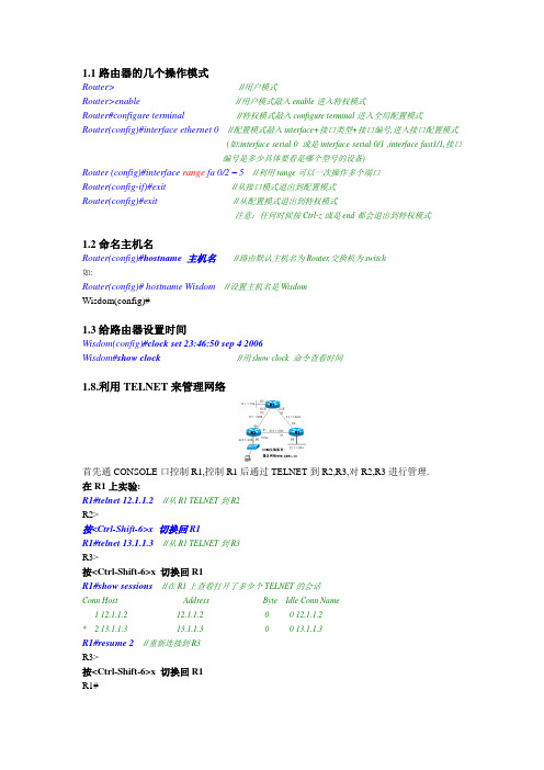
1.1路由器的几个操作模式Router>//用户模式Router>enable//用户模式敲入enable进入特权模式Router#configure terminal//特权模式敲入configure terminal进入全局配置模式Router(config)#interface ethernet 0//配置模式敲入interface+接口类型+接口编号,进入接口配置模式(如:interface serial 0 或是interface serial 0/1 ,interface fast1/1,接口编号是多少具体要看是哪个型号的设备)Router (config)#interface range fa 0/2 – 5//利用range可以一次操作多个端口Router(config-if)#exit //从接口模式退出到配置模式Router(config)#exit//从配置模式退出到特权模式注意:任何时候按Ctrl-z或是end都会退出到特权模式1.2命名主机名Router(config)#hostname 主机名//路由默认主机名为Router,交换机为switch如:Router(config)#hostname Wisdom//设置主机名是WisdomWisdom(config)#1.3给路由器设置时间Wisdom(config)#clock set 23:46:50 sep 4 2006Wisdom#show clock//用show clock 命令查看时间1.8.利用TELNET来管理网络首先通CONSOLE口控制R1,控制R1后通过TELNET到R2,R3,对R2,R3进行管理.在R1上实验:R1#telnet 12.1.1.2//从R1 TELNET到R2R2>按<Ctrl-Shift-6>x 切换回R1R1#telnet 13.1.1.3//从R1 TELNET到R3R3>按<Ctrl-Shift-6>x 切换回R1R1#show sessions//在R1上查看打开了多少个TELNET的会话Conn Host Address Byte Idle Conn Name1 12.1.1.2 12.1.1.2 0 0 12.1.1.2* 2 13.1.1.3 13.1.1.3 0 0 13.1.1.3R1#resume 2//重新连接到R3R3>按<Ctrl-Shift-6>x 切换回R1R1#R1#disconnect 1//从R1是主动断开到R2的连接(断开一个TELNET的会话)在R2上实验:R2#show users//在R2上查看有谁登录到路由器Line User Host(s) Idle Location* 0 con 0 idle 00:00:002 vty 0 idle 00:01:52 12.1.1.1R2#clear line 2//发现有人TELNET过来,把他清除R2#show usersLine User Host(s) Idle Location* 0 con 0 idle 00:00:00注意:Show session和show user的区别Disconnect 和Clear line的区别Ctrl+shift+6 x 和resume1.9 PING、TraceRoute、Debug、Sysloga.使用PING命令R1#ping 12.1.1.2如果ping的结果是!!!!!则表明网络正常.如果ping的结果是…..则表明网络不通.如果ping的结果是U.U.U则表明下一跳不可达.b.使用traceroute命令, 在网络层上追踪源到目的地址所经过的路由器.(或是数据包经过的路径)例:R2#traceroute 33.1.1.3Tracing the route to 33.1.1.31 12.1.1.1 4 msec 4 msec 4 msec2 13.1.1.34 msec 4 msec *//从以上可以看出从R2 到达33.1.1.3经过了12.1.1.1和13.1.1.3两个路由器例:………………………………………………………………………………………………………………….3.3使用串口管理交换机。
(完整word版)利用CiscoPacketTracer模拟交换机的基本配置
(完整word版)利用CiscoPacketTracer模拟交换机的基本配置交换机的配置课程名称:计算机网络实用技术实验题目:交换机的配置实验目的:掌握交换机的配置方法。
实验设备:计算机1台、Cisco Packet Tracer 模拟软件1套。
实验内容:1、交换机命令模式间的切换。
2、交换机的基本配置。
3、vlan 的配置4、vlan 间路由实验过程:一、交换机命令模式间的切换1、模拟网络环境打开RouterSim 模拟软件,添加一台交换机(以3550为例)。
双击交换机图标,打开命令行窗口。
2、命令模式间的切换User Exec 口令enable 命令configure 命令interface 命令line 命令vlan database 命令LoginUser Exec 模式Privileged Exec 模式Global Configuration 模式VLAN Database 模式Line Configuration 模式Interface Configuration 模式(1)User EXEC 模式(用户模式)提示符:Switch>访问方法:回车,开始一个进程。
退出方法:输入exit 命令离开该模式。
(2)Privileged EXEC 模式(特权模式)提示符:Switch#访问方法:在用户模式中输入enable命令。
退出方法:输入exit或disable 命令,返回到用户模式。
(3)VLAN Database 模式(VLAN 配置模式)提示符:Switch(vlan)#访问方法:在特权模式中输入vlan database命令。
退出方法:输入exit 命令,返回到特权模式。
(4)Global configuration 模式(全局配置模式)提示符:Switch(config)#访问方法:在特权模式中输入configure 命令。
退出方法:输入exit命令或end 命令,或者键入Ctrl+Z 组合键,返回到特权模式。
ciscocatalyst3550系列交换机
Cisco 3500 系列交换机一、应用领域Catalyst 3500 XL系列交换机是具备高性能,易于管理,灵活配置的可堆叠的以太网/快速以太网/千兆以太网交换机。
Catalyst 3500 XL系列交换机再加上Cisco的交换集群技术,可以实现多达16个Catalyst 3500XL,Catalyst 2900XL,Catalyst 1900系列交换机互联,超过380个端口通过一个IP地址进行管理。
同时Catalyst 3500XL交换机的高性能IOS软件配合Cisco Visual Switch Manager(CVSM)交换机网管软件可以方便实现以主页方式的设置和网管。
Catalyst 3500XL系列交换机拥有Cisco GigaStack千兆堆叠的千兆接口卡(GBIC),可以实现灵活的交换机堆叠和扩展。
二、设备特性1、特性802.1d 生成树冗余堆叠连接,可选600W 交流冗余电源,平均无故障时间超过150000小时保修Cisco承诺终生保修2、规格表1 CISCO WS-C3550-24TS-S详细参数主要参数产品类型:企业级交换机应用层级:三层传输速率:10/100Mbps 交换方式:存储-转发背板带宽:32Gbps包转发率:6.5Mpps MAC地址表:12K端口参数端口结构:非模块化端口数量:26个端口描述:24个以太网10/100Mpps端口,2个基于SFP的千兆位以太网端口传输模式:支持全双工功能特性堆叠功能:可堆叠VLAN:支持QOS:支持网络管理:SNMP,CLI,Web,管理软件其它参数产品尺寸:445×301×44mm 产品重量:3.6kg三、外观图1 Cisco Nexus 3550 四、模块堆叠模块千兆堆叠接口卡(GigaStack GBIC)适用于Catalyst 2900/3500 XL系列交换机的GBIC 插槽,利用最长1m的铜芯双绞线电缆连线技术,实现如下的两种堆叠连接方式。
思科三层交换机路由功能配置教程

思科三层交换机路由功能配置教程交换机工作于OSI参考模型的第二层,即数据链路层。
交换机内部的CPU会在每个端口成功连接时,通过将MAC地址和端口对应,形成一张MAC表,在思科三层交换机中,路由功能是很重要的功能,需要做好正确配置,下面一起看看!方法步骤而三层交换机可以在网络层配置路由功能,使不同网段的设备可以通信。
现以思科3550交换机为例配置三层路由功能。
以实现如下拓扑通信。
----------------------------------| 思科3550三层交换机 |---- -------------------- -------50.1.1.1 (23口) 60.1.1.1(24口)|| |||| ||50.1.1.2 60.1.1.2(pc1) (pc2)配置23口:Switch#enableSwitch#configure terminalSwitch(config)#interface fastEthernet 0/23Switch(config)ip addr 50.1.1.1 255.255.255.0Switch(config-if)#no switchportSwitch(config-if)#no shutdownSwitch(config-if)#end类似的配置24口:Switch#enableSwitch#configure terminalSwitch(config)#interface fastEthernet 0/24Switch(config)ip addr 60.1.1.1 255.255.255.0Switch(config-if)#no switchportSwitch(config-if)#no shutdownSwitch(config-if)#end打开交换机路由转发开关:Switch#configure terminalSwitch(config)#ip routingSwitch(config)#ip cef (这个默认是打开的)此时可以查看下23口的状态:Switch#show interfaces fastEthernet 0/23此时在交换机上ping两个口的地址成功:Switch#ping 50.1.1.1Type escape sequence to abort.Sending 5, 100-byte ICMP Echos to 50.1.1.1, timeout is 2 seconds:Success rate is 100 percent (5/5), round-trip min/avg/max = 1/1/1 msSwitch#ping 60.1.1.1Type escape sequence to abort.Sending 5, 100-byte ICMP Echos to 60.1.1.1, timeout is 2 seconds:Success rate is 100 percent (5/5), round-trip min/avg/max = 1/1/4 msSwitch#pc1(win7)增加路由:到60.1.1.0/24的数据包通过50.1.1.1转发:route ADD 60.1.1.0 MASK 255.255.255.0 50.1.1.1 METRIC 3 对应的pc2也增加路由:route ADD 50.1.1.0 MASK 255.255.255.0 60.1.1.1 METRIC 3 此时50.1.1.2和60.1.1.2即可通信。
在三层交换机配置DHCP的方法
在三层交换机配置DHCP的方法交换机的主要功能包括物理编址、网络拓扑结构、错误校验、帧序列以及流控。
交换机还具备了一些新的功能,如对VLAN(虚拟局域网)的支持、对链路会聚的支持,甚至有的还具有防火墙的功能。
通过本实验掌握,如何在Cisco Catalyst 3550交换机来配置DHCP效劳,实现对内网主机分配IP地址,网关,DNS,WINS,租期,域名等。
第一步:Catalyst 3550底层配置Switch(config)#no ip do loSwitch(config)#line con 0Switch(config-line)#no exec-tSwitch(config-line)#logg synSwitch(config-line)#host SwitchDhcpSwitchDhcp(config)#int f0/1SwitchDhcp(config-if)#no shSwitchDhcp(config-if)#spanning-tree portfast//连接终端的接口下,开启portfast特性,跳过生成树的选举,接口立即进入转发状态%Warning: portfast should only be enabled on ports connected to a singlehost. Connecting hubs, concentrators, switches, bridges, etc... to thisinterface when portfast is enabled, can cause temporary bridging loops.Use with CAUTION%Portfast has been configured on FastEther0/1 but will onlyhave effect when the interface is in a non-trunking mode.SwitchDhcp(config-if)#end第二步: 开启DHCP效劳,定义分配地址池范围及掩码,网关,DNS,域名,租期等//全局下开启DHCP效劳,该效劳默认是关闭的SwitchDhcp(config)#service dhcp//关闭DHCP分配冲突,日志记录消息SwitchDhcp(config)#no ip dhcp conflict logging//创立DHCP地址池,名称为可以是任意字符SwitchDhcp(config)#ip dhcp pool cisco//指定要通过DHCP分配的网段和掩码,还有另外一种写法(192.168.0.0 255.255.255.0)SwitchDhcp(dhcp-config)#work 192.168.0.0 /24//指定分配的网关地址SwitchDhcp(dhcp-config)#default-router 192.168.0.1//指定DHCP域名,域名可以为任意字符SwitchDhcp(dhcp-config)#domain-name .cisco..//指定PC通过DHCP分配到DNS地址,(这里指定的是当地电信部门的真实地址,全国各地市不一样的)SwitchDhcp(dhcp-config)#dns 218.30.19.40 61.134.1.4//bios效劳器地址,可选的配置SwitchDhcp(dhcp-config)#bios-name-server 192.168.0.10//指定通过DHCP分配到地址,租期为永久SwitchDhcp(dhcp-config)#lease infiniteSwitchDhcp(dhcp-config)#end//指定不通过DHCP 地址池中分配的地址,也就是排除的地址。
限制流量之cisco配置

1)建立一个访问控制列表(ACL); 2)建立一个类(CLASS),并在这个类上引用刚建立的那个访问控制列表(ACL); 3)建立一个策略(POLICY),在这个策略上指定相应的带宽,并引用相应的类; 4)将这个策略应用具体的端口上。
具体操作如下: CISCO3550交换机: 1、在交换机上启动QOS Switch(config)#mls qos //在交换机上启动QOS 2、定义访问控制列表 Switch(config)#access-list 1 permit 10.59.0.0 0.0.255.255 //针对10.59/16这个网段进行上行流量控制 Switch(config)#access-list 101 permit ip any 10.59.0.0 0.0.255.255 //针对10.59/16这个网段进行下行流量控制 3、定义类,并和上面定义的访问控制列表绑定 Switch(config)# class-map xsup //定义上行的类,并绑定访问列表 1 Switch(config-cmap)# match access-group 1 Switch(config-cmap)# exit Switch(config)# class-map xsdown Switch(config-cmap)# match access-group 101 //定义下行的类,并绑定访问列表101 Switch(config-cmap)# exit 4、定义策略,把上面定义的类绑定到该策略 Switch(config)# policy-map xsup //定义上行的速率为1M,超过的丢弃 Switch(config-pmap)# class xsup Switch(config-pmap-c)# trust dscp Switch(config-pmap-c)# police 1000000 1000000 exceed-action drop Switch(config)# policy-map xsdown //定义下行的速率为1M,超过的丢弃 Switch(config-pmap)# class xsdown Switch(config-pmap-c)# trust dscp Switch(config-pmap-c)# police 1000000 1000000 exceed-action drop Switch(config-pmap-c)# exit 5、在接口上运用策略 Switch(config)# interface fa0/1 Switch(config-if)# service-policy input xsup Switch(config)# interface fa0/24 Switch(config-if)# service-policy input xsdown //24口为上行接口 华为3552交换机: 1、sys [ZXJF_3552]acl name xs advanced //建立名为xs的高级ACL [ZXJF_3552-acl-adv-chen]rule 1 permit ip source 10.67.0.0 0.0.255.255 //允许67网段的主机通过 [ZXJF_3552-acl-adv-chen]q 2、sys [ZXJF_3552]int e0/1 [ZXJF_3552-Ethernet0/1]packet-filter inbound ip-group xs//在1口上激活了ACL“xs” 3、sys [ZXJF_3552]int e0/1 [ZXJF_3552-Ethernet0/1]traffic-limit inbound ip-group xs 10240 1280000 1280000 //对1口上接收的流量速率限制为10M=10240kbps。
锐捷交换机配置手册完整

锐捷S3550配置手册第一部分:交换机概述一:交换机的几种配置方法控制台用一台计算机作为控制台和网络设备相连,通过计算机对网络设备进行配置。
远程登录通过一台连接在网络中的计算机,用Telnet命令登录网络设备进行配置。
其它配置方法除了控制台和远程登录之外,还有其它一些配置方法配置网络设备。
二:命令行(CLI)操作命令模式交换机和路由器的命令是按模式分组的,每种模式中定义了一组命令集,所以想要命令模式的切换交换机和路由器的模式大体可分为四层:用户模式→特权模式→全局配置模式→其CLI命令的编辑技巧CLI(命令行)有以下特点。
常见CLI错误提示% Ambiguous command: "show c"使用no 和default 选项很多命令都有no 选项和default 选项。
三:交换机的初始化配置交换机的初始化配置setup命令四:配置文件的保存、查看与备份查看配置文件模式:特权配置模式。
保存配置文件保存配置文件就是把running-config 保存为startup-config。
删除配置文件删除配置文件就是把NVRAM中的startup-config 删除。
备份配置文件通常我们把配置文件备份到TFTP服务器上,在需要时可以再从TFTP服务器上把五:文件系统文件系统概述交换机和路由器用一个并行Flash作为辅助存储器存储文件,Flash是一个可读可文件操作所有文件操作都是在特权模式下进行。
目录操作Flash中的文件可以使用树形的目录结构,文件可以存放在不同的子目录中,也可六:系统文件的备份与升级搭建环境在备份和升级时需要搭建通信环境,让设备和计算机间可以传输文件。
有三个方案:用TFTP传输文件准备工作:用Xmodem传输文件准备工作:ROM监控模式进入ROM监控模式有两种方法:七:密码丢失的解决方法第二部分:交换机的基本配置一:配置主机名主机名用于标识交换机和路由器,通常它会作为提示符的一部分显示在命令提示符二:配置口令配置控制台口令控制台口令是通过控制台登录交换机或路由器时设置的口令。
- 1、下载文档前请自行甄别文档内容的完整性,平台不提供额外的编辑、内容补充、找答案等附加服务。
- 2、"仅部分预览"的文档,不可在线预览部分如存在完整性等问题,可反馈申请退款(可完整预览的文档不适用该条件!)。
- 3、如文档侵犯您的权益,请联系客服反馈,我们会尽快为您处理(人工客服工作时间:9:00-18:30)。
cisco3550交换机配置手册说明本手册只包括日常使用的有关命令及特性,其它未涉及的命令及特性请参考英文的详细配置手册。
产品特性3550EMI是支持二层、三层功能(EMI)的交换机支持VLAN·到1005 个VLAN·支持VLAN ID从1到4094( IEEE 802.1Q 标准)·支持ISL及IEEE 802.1Q封装安全·支持IOS标准的密码保护·静态MAC地址映射·标准及扩展的访问列表支持,对于路由端口支持入出双向的访问列表,对于二层端口支持入的访问列表·支持基于VLAN的访问列表3层支持(需要多层交换的IOS)· HSRP· IP路由协议o RIP versions 1 and 2o OSPFo IGRP及EIGRPo BGP V ersion 4监视·交换机LED指示端口状态· SPAN及远端SPAN (RSPAN) 可以监视任何端口或VLAN的流量·内置支持四组的RMON监控功能(历史、统计、告警及事件)· Syslog功能其它功能:支持以下的GBIC模块:· 1000BASE-T GBIC: 铜线最长100 m· 1000BASE-SX GBIC: 光纤最长1804 feet (550 m)· 1000BASE-LX/LH GBIC: 光纤最长32,808 feet (6 miles or 10 km)· 1000BASE-ZX GBIC: 光纤最长328,084 feet (62 miles or 100 km)配置端口配置一组端口命令目的Step 1 configure terminal 进入配置状态Step 2 interface range {port-range} 进入组配置状态Step 3 可以使用平时的端口配置命令进行配置Step 4 end 退回Step 5 show interfaces [interface-id] 验证配置Step 6 copy running-config startup-config 保存当使用interface range命令时有如下的规则:·有效的组范围:o vlan从1 到4094o fastethernet 槽位/{first port} - {last port}, 槽位为0o gigabitethernet槽位/{first port} - {last port},槽位为0o port-channel port-channel-number - port-channel-number, port-channel号从1到64·端口号之间需要加入空格,如:interface range fastethernet 0/1 – 5 是有效的,而interface range fastethernet 0/1-5 是无效的.· interface range 命令只能配置已经存在的interface vlan·所有在同一组的端口必须是相同类别的。
见以下例子:Switch# configure terminalSwitch(config)# interface range fastethernet0/1 - 5Switch(config-if-range)# no shutdownSwitch(config-if-range)#*Oct 6 08:24:35: %LINK-3-UPDOWN: Interface FastEthernet0/1, changed state to up*Oct 6 08:24:35: %LINK-3-UPDOWN: Interface FastEthernet0/2, changed state to up*Oct 6 08:24:35: %LINK-3-UPDOWN: Interface FastEthernet0/3, changed state to up*Oct 6 08:24:35: %LINK-3-UPDOWN: Interface FastEthernet0/4, changed state to up*Oct 6 08:24:35: %LINK-3-UPDOWN: Interface FastEthernet0/5, changed state to up*Oct 6 08:24:36: %LINEPROTO-5-UPDOWN: Line protocol on Interface FastEthernet0/05,changed state to up*Oct 6 08:24:36: %LINEPROTO-5-UPDOWN: Line protocol on Interface FastEthernet0/3, changedstate to up*Oct 6 08:24:36: %LINEPROTO-5-UPDOWN: Line protocol on Interface FastEthernet0/4, changedstate to up以下的例子显示使用句号来配置不同类型端口的组:Switch# configure terminalSwitch(config)# interface range fastethernet0/1 - 3, gigabitethernet0/1 - 2Switch(config-if-range)# no shutdownSwitch(config-if-range)#*Oct 6 08:29:28: %LINK-3-UPDOWN: Interface FastEthernet0/1, changed state to up*Oct 6 08:29:28: %LINK-3-UPDOWN: Interface FastEthernet0/2, changed state to up*Oct 6 08:29:28: %LINK-3-UPDOWN: Interface FastEthernet0/3, changed state to up*Oct 6 08:29:28: %LINK-3-UPDOWN: Interface GigabitEthernet0/1, changed state to up*Oct 6 08:29:28: %LINK-3-UPDOWN: Interface GigabitEthernet0/2, changed state to up*Oct 6 08:29:29: %LINEPROTO-5-UPDOWN: Line protocol on Interface GigabitEthernet0/ 1,changed state to up*Oct 6 08:29:29: %LINEPROTO-5-UPDOWN: Line protocol on Interface FastEthernet0/ 2,changed state to up*Oct 6 08:29:29: %LINEPROTO-5-UPDOWN: Line protocol on Interface FastEthernet0/ 3,changed state to up配置二层端口3550的所有端口缺省的端口都是二层口,如果此端口已经配置成三层端口的话,则需要用switchport来使其成为二层端口。
配置端口速率及双工模式可以配置快速以太口的速率为10/100Mbps及千兆以太口的速率为10/100/1000-Mbps; 但对于GBIC端口则不能配置速率及双工模式,有时可以配置nonegotiate,当需要联接不支持自适应的其它千兆端口时命令目的Step 1 configure terminal 进入配置状态.Step 2 interface interface-id 进入端口配置状态.Step 3 speed {10 | 100 | 1000 | auto | nonegotiate} 设置端口速率注 1000 只工作在千兆口. GBIC模块只工作在1000 Mbps下. nonegotiate 只能在这些GBIC上用 1000BASE-SX, -LX, and -ZX GBIC.Step 4 duplex {auto | full | half} 设置全双工或半双工.Step 5 end 退出Step 6 show interfaces interface-id 显示有关配置情况Step 7 copy running-config startup-config 保存Switch# configure terminalSwitch(config)# interface fastethernet0/3Switch(config-if)# speed 10Switch(config-if)# duplex half端口描述命令目的Step 1 configure terminal 进入配置模式Step 2 interface interface-id 进入要加入描述的端口Step 3 description string 加入描述 (最多240个字符).Step 4 end 退回.Step 5 show interfaces interface-id descriptionorshow running-config 验证.Step 6 copy running-config startup-config 保存Use the no description interface configuration command to delete the description.This example shows how to add a description on Fast Ethernet interface 0/4 and to verify the description:Switch# config terminalEnter configuration commands, one per line. End with CNTL/Z.Switch(config)# interface fastethernet0/4Switch(config-if)# description Connects to MarketingSwitch(config-if)# endSwitch# show interfaces fastethernet0/4 descriptionInterface Status Protocol DescriptionFa0/4 up down Connects to Marketing配置三层口Catalyst 3550支持三种类型的三层端口:· SVIs: 即interface vlanNote 当生成一个interface Vlan时,只有当把某一物理端口分配给它时才能被激活·三层以太网通道口(EtherChannel)· .路由口:路由口是指某一物理端口在端口配置状态下用no switchport命令生成的端口所有的三层都需要IP地址以实现路由交换配置步骤如下:命令目的Step 1 configure terminal 进入配置状态Step 2 interface {{fastethernet | gigabitethernet} interface-id} | {vlan vlan-id} | {port-channel port-channel-number} 进入端口配置状态Step 3 no switchport 把物理端口变成三层口Step 4 ip address ip_address subnet_mask 配置IP地址和掩码Step 5 no shutdown 激活端口Step 6 end 退出Step 7 show interfaces [interface-id]show ip interface [interface-id]show running-config interface [interface-id] 验证配置Step 8 copy running-config startup-config 保存配置配置举例如下:Switch# configure terminalEnter configuration commands, one per line. End with CNTL/Z.Switch(config)# interface gigabitethernet0/2Switch(config-if)# no switchportSwitch(config-if)# ip address 192.20.135.21 255.255.255.0Switch(config-if)# no shutdownSwitch(config-if)# endshow ip interface命令:Switch# show ip interface gigabitethernet0/2GigabitEthernet0/2 is up, line protocol is upInternet address is 192.20.135.21/24Broadcast address is 255.255.255.255Address determined by setup commandMTU is 1500 bytesHelper address is not setDirected broadcast forwarding is disabled<output truncated>监控及维护端口监控端口和控制器的状态主要命令见下表:Show Commands for Interfaces Command 目的show interfaces [interface-id] 显示所有端口或某一端口的状态和配置.show interfaces interface-id status [err-disabled] 显示一系列端口的状态或错误-关闭的状态show interfaces [interface-id] switchport 显示二层端口的状态,可以用来决定此口是否为二层或三层口。