单机无穷大算例系统说明1214
Autodesk Nastran 2023 参考手册说明书
FILESPEC ............................................................................................................................................................ 13
DISPFILE ............................................................................................................................................................. 11
File Management Directives – Output File Specifications: .............................................................................. 5
BULKDATAFILE .................................................................................................................................................... 7
单机无穷大电力系统的数学模型

单机无穷大电力系统的数学模型(含原动机)1 单机无穷大系统(Single Machine Infinite Bus,SMIB)无穷大系统无穷大容量水库-单引水管道-水轮发电机组-无穷大容量电力系统,简称为简单水电系统。
系统2 单机无穷大系统数学模型2.1 水力系统-水轮机线性化模型 2.1.1 水力系统线性化模型水力系统一般使用近似的线性化模型。
水轮机导叶(水门)处的水压流量传递函数为h ()()()h s G s q s ∆=∆ (1)式中 h ∆——水轮机工作水头的增量;q ∆——水轮机流量的增量。
设单引水管道水库取水口处水压恒定,则rw r h 2r 42()th 2T s T T G s s T s αα+⎛⎫=-⋅⋅+ ⎪⎝⎭ (2)式中 w T ——水流惯性时间常数,s ; r T ——水击波反射时间常数,s ;α——水力摩擦阻力系数。
若不考虑水力摩擦阻力,即0α=,则式(2)可简化为w rh r 2()th 2T T G s s T ⎛⎫=-⋅⎪⎝⎭ (3)由2th 12xx x ≈+,式(3)进一步简化为 w h 22r ()18T sG s T s=-+ (4) 式(4)为常用的水力系统弹性水击模型。
当引水管道较短时,近似取r 0T =,式(4)退化为刚性水击模型h w ()G s T s =- (5)2.1.2 水轮机线性化模型当水轮机工况变化较为缓慢时,可以采用稳态关系式表示力矩和流量的变化情况。
以水轮机额定运行参数为基准,混流式水轮机的力矩和流量的标么形式表达式为()m f ,,m y h ω= (6)()g ,,q y h ω= (7)式中 m m ——水轮机输出机械力矩,p.u.;q ——水轮机流量,p.u.;y ——水轮机导叶开度,p.u.;ω——水轮机机械转速,p.u.;h ——水轮机工作水头,p.u.。
将式(6)和(7)在工作点0附近线性化得m m mm 000my m ωmh m m m m y hy h e y e e hωωω∂∂∂∆=∆+∆+∆∂∂∂=∆+∆+∆ (8)000qy q ωqh q q q q y hy h e y e e hωωω∂∂∂∆=∆+∆+∆∂∂∂=∆+∆+∆ (9)式中 my e 、mh e 、m ωe ——水轮机力矩对导叶开度、水头和转速的传递系数;qy e 、qh e 、q ωe ——水轮机流量对导叶开度、水头和转速的传递系数。
算力冗余设计-概述说明以及解释

算力冗余设计-概述说明以及解释1.引言1.1 概述算力冗余设计是指在计算机系统中为了提高系统的可靠性和性能而采取的一种设计方案。
通过在系统中引入额外的算力资源,可以在发生故障或突发负载情况下保证系统的正常运行,提高系统的稳定性和可用性。
随着计算机应用的不断扩展和复杂化,对系统的可靠性和性能要求也越来越高。
在这种背景下,算力冗余设计成为了一种重要的解决方案。
通过设计合理的算力冗余方案,可以有效应对系统故障和负载波动带来的挑战,保证系统的稳定运行和高效处理。
本文将深入探讨算力冗余的概念、设计重要性以及实现方法,希望能为读者提供一些有益的思考和启示。
1.2 文章结构:本文主要分为三个部分,分别是引言、正文和结论。
在引言部分,将对算力冗余设计进行概述,介绍文章结构和目的,使读者对本文内容有一个整体的了解。
在正文部分,将深入探讨算力冗余的概念,分析设计算力冗余的重要性,以及介绍算力冗余的实现方法。
通过具体的案例和技术细节,阐述算力冗余设计的必要性和实施方式。
在结论部分,对整篇文章进行总结,概括算力冗余设计的应用前景,展望未来的发展趋势,为读者提供对于算力冗余设计的深入思考和展望。
1.3 目的算力冗余设计的目的在于提高系统的可靠性和稳定性。
通过引入冗余的算力资源,系统可以在某些组件出现故障或性能下降时,仍能保持正常运行。
这样可以有效避免单点故障,提高系统的稳定性和可用性。
另外,算力冗余设计也可以提高系统的性能和处理能力。
通过合理配置冗余算力资源,可以在高负载时自动触发冗余资源,从而提升系统的整体性能和响应速度。
总的来说,算力冗余设计的目的是为了提高系统的可靠性、稳定性和性能,确保系统能够持续正常运行并应对各种临时性故障或挑战。
2.正文2.1 算力冗余的概念算力冗余是指在计算机系统中为了提高系统的可靠性和稳定性而设计的一种策略。
在网络中,算力冗余通常指的是在数据中心或者分布式系统中部署额外的计算资源,以应对计算资源的突发故障或者负载过大的情况。
超级计算技术的基本概念和原理

超级计算技术的基本概念和原理超级计算技术是一种高度先进的计算机技术,用于处理复杂、大规模的计算问题。
它广泛应用于科学研究、工程设计、气象预测、金融模拟等领域,以提供快速而准确的计算结果。
本文将介绍超级计算技术的基本概念和原理,帮助读者更好地理解这一领域的重要性和应用。
首先,我们来了解超级计算技术的基本概念。
超级计算是指利用大型并行处理系统进行高速计算的技术。
它通过将多台计算机连接在一起,形成一个庞大的计算机网络,每台计算机担当一个计算节点,共同完成计算任务。
超级计算机的核心是它的并行计算能力,能够在数千甚至数百万个处理器之间进行数据交换和计算任务的分配。
超级计算机通常由多个计算节点、存储节点和网络节点组成。
计算节点负责执行实际的计算任务,存储节点用于存储数据和中间结果,网络节点用于连接各个节点之间的通信。
这种分布式计算的架构使得超级计算机能够同时处理多个任务,并以极高的效率完成计算任务。
超级计算技术的原理主要包括并行计算、向量计算和分布式存储。
并行计算是指将计算任务分成多个独立的部分,交给不同的处理器同时计算,最后将结果合并得到最终结果。
这种方式能够大大提高计算速度,减少计算时间。
向量计算是指利用向量处理器进行计算,通过同时对多个数据进行操作,提高计算效率。
分布式存储是指将大量数据分散存储在不同的存储节点上,通过网络节点进行数据的读取和传输,避免了单个节点数据存储容量的限制,提高了数据处理的效率和可靠性。
超级计算机的性能通常以峰值速度、持续速度和吞吐量来衡量。
峰值速度是指超级计算机能够达到的最大计算速度,持续速度是指超级计算机在长时间计算中的平均计算速度,吞吐量是指超级计算机在单位时间内能够处理的任务数量。
超级计算技术在各领域都发挥着重要作用。
在科学研究领域,超级计算机能够模拟复杂的物理、化学等问题,帮助科学家更好地理解自然界的规律。
在工程设计领域,超级计算机能够进行大规模的模拟和优化,加速产品设计和开发。
辛迪控制系统SIMATIC PCS neo功能库手册说明书
5
Monitoring blocks
6
Controller blocks
7
Motor and valve blocks
8
Interlock blocks
9
Mathematical block
10
Counter blocks
11
Digital logic blocks
12
Services
13
14 TCP communication blocks
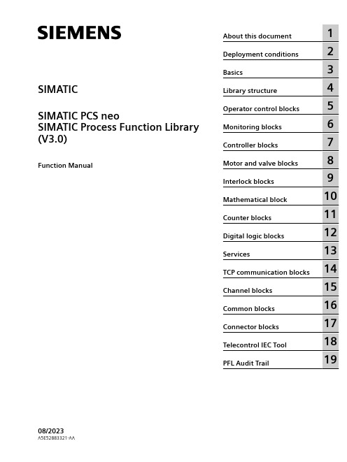
SIMATIC SIMATIC PCS neo SIMATIC Process Function Library (V3.0)
Function Manual
About this document
1
Deployment conditions
2
Basics
3
Library structure
4
Operator control blocks
CAUTION
indicates that minor personal injury can result if proper precautions are not taken.
NOTICE
indicates that property damage can result if proper precautions are not taken. If more than one degree of danger is present, the warning notice representing the highest degree of danger will be used. A notice warning of injury to persons with a safety alert symbol may also include a warning relating to property damage.
CimatronE12新功能介绍
CimatronE12新功能介绍CimatronE 12 新功能目录建模 ..................................................................... ........................................................................ ............... 6 , 曲线 ..................................................................... ........................................................................ ........ 6 , 曲面 ..................................................................... ........................................................................ ...... 11 , 实体 ..................................................................... ........................................................................ ...... 15 装配 ..................................................................... ........................................................................ ............. 21 , 运动模拟的改善 ..................................................................... ........................................................... 21 , 装配树中的文件夹 ..................................................................... ........................................................ 22 , 设置的增强 ..................................................................... ................................................................... 23 , 把多个切除操作组合成单个特征(仅限于增加) .................................................................... ......... 24 , 编辑添加允许改变面 ..................................................................... .................................................... 25 , BOM表中允许子装配作为代表...................................................................... ................................... 26 , 周期分析–打断所有...................................................................... ................................................... 27 , 关联和取消关联在装配镜像中 ..................................................................... ..................................... 28 草图 ..................................................................... ........................................................................ ............. 29 , 草图增加了尺寸关联和公式 ..................................................................... ......................................... 29 , 撤销样条线点 ..................................................................... ............................................................... 30 , 不同颜色显色的参考点 ..................................................................................................................... 31 工程图...................................................................... ........................................................................ ......... 32 , 工程图以及创建视图 ..................................................................... .................................................... 32 , 符号 ..................................................................... ........................................................................ ...... 35 , 其他 ..................................................................... ........................................................................ ...... 38 模架库...................................................................... ........................................................................ ......... 41 , 提供主要模具库的更新 ..................................................................... ................................................ 41 分析工具 ..................................................................... ........................................................................ ...... 42 , 拔模角度和方向分析恢复默认参数 ..................................................................... .............................. 42 , 方向分析输出PDF .................................................................... ........................................................ 43 , 新的曲率分析并输出PDF .................................................................... ............................................. 44 , 在测量工具里计算体积显示曲面 ..................................................................... .................................. 45 , 提高了三坐标测量 ..................................................................... ........................................................ 46 , 设定质量单位 ..................................................................... ............................................................... 47 通用CAD .................................................................... ........................................................................ .. (48)iCimatronE 12 新功能 , 新的参数关联功能 ..................................................................... ........................................................ 48 , 继承过滤器工具最后设置的所有功能 ..................................................................... .......................... 49 , 特征树滚动至末端 ..................................................................... ........................................................ 50 新的挂台工具............................................................................................................................................51 新的镶件设计...................................................................... ......................................................................52 顶针列表 ..................................................................... ........................................................................ ...... 53 仅靠分模面切出模仁造型 ..................................................................... .................................................... 54 斜顶切除新增交互功能 ..................................................................... ........................................................ 55 斜顶切槽的装配特征 ..................................................................... ........................................................... 56 ECO 改进 ..................................................................... ........................................................................ .... 57 顶针切槽时转移孔属性 ..................................................................... ........................................................ 58 识别手动附属的曲面 ..................................................................... ........................................................... 59 水路设计 ..................................................................... ........................................................................ ...... 60 , Moldex 3D 冷却仿真 ..................................................................... .................................................... 60 , 冷却项目的文件夹 ..................................................................... ........................................................ 61 , 单独控制水路参数 ..................................................................... ........................................................ 62 , 冷却回路分析并支持异形水路 ..................................................................... ..................................... 63 型腔模报价改进 ..................................................................... . (64)新的固定工具...................................................................... ......................................................................64 新的镶件设计...................................................................... ......................................................................65 坯料和展开异型面的高级约束...................................................................... ............................................ 66 级进模具设计ECO管理器 ..................................................................... .................................................... 67 挂台长度更好控制 ..................................................................... ............................................................... 68 线框避空可以负偏移值 ..................................................................... ........................................................ 69 回弹变化分析...................................................................... ......................................................................70 线框避空–优化的半径 ..................................................................... ....................................................... 71 添加压料零件...................................................................... ......................................................................72 半径值的传送轮廓 ..................................................................... (73)iiCimatronE 12 新功能 2.5轴铣削...................................................................... ........................................................................ ... 74 , 高效加工–切入点控制 ...................................................................................................................... 74 自动钻孔 ..................................................................... ........................................................................ ...... 75 , 支持序列式 ..................................................................... ................................................................... 75 , 孔分段显示 ..................................................................... . (78)粗加工操作 ..................................................................... ........................................................................ .. 79 , 粗加工使用 ..................................................................... ................................................................... 79 , 高效加工 ..................................................................... ......................................................................80 精加工操作 ..................................................................... ........................................................................ .. 82 , TP点均匀分布 ..................................................................... .............................................................. 82 , 新超速模拟在精加工毛胚的变化 ..................................................................... .................................. 83 清角改进 ..................................................................... ........................................................................ ...... 84 , 任意刀具组合与提高加工效率 ..................................................................... ..................................... 84 , 避免瀑布式刀路 ..................................................................... ........................................................... 85 , 统一进退刀 ..................................................................... ................................................................... 86 , 路径延伸 ..................................................................... ......................................................................87 5轴加工...................................................................... ........................................................................ ...... 88 , 多轴粗铣 ..................................................................... ......................................................................88 , 端口铣削 ...........................................................................................................................................89 NC设置和材料 ..................................................................... .................................................................... 90 , NC设置...................................................................... .......................................................................90 , 支持多种材料 ..................................................................... ............................................................... 91 提高毛坯精度...................................................................... ......................................................................92 , 显示剩余毛坯 ..................................................................... ............................................................... 92 , 多方向毛坯 ..................................................................... ................................................................... 93 , 毛坯精度 ..................................................................... ......................................................................94 , 毛坯计算 ...........................................................................................................................................95 机床仿真 ..................................................................... ........................................................................ ...... 96 , 机床仿真单一环境 ..................................................................... ........................................................ 96 , 新的机床仿真 ..................................................................... ............................................................... 97 , 定义程序时的机床显示 ..................................................................... ................................................ 98 , 材料去除仿真——刀具补偿 ..................................................................... ......................................... 99 后处理和报告...................................................................... .. (100)iiiCimatronE 12 新功能 , 工作管理器 ..................................................................... ................................................................. 100 , GPP2内部运行 ............................................................................................................................... 101 , 后处理器定义文件的网络地址 ..................................................................... ................................... 102 , 电极报告里图片的改进 ..................................................................... .............................................. 103 程序自动化 ..................................................................... ........................................................................ 104 , 毛坯定义增强 ..................................................................... ............................................................. 104 , 新文件自动加载NC模板 ..................................................................... ........................................... 105 , 增强自动颜色 ..................................................................... ............................................................. 106 CAD辅助工具 ..................................................................... ................................................................... 109 , 随形圆角 ..................................................................... ....................................................................109 , 几何边界 (外边界/内边界) ............................................................................................................... 110 设计 ..................................................................... ........................................................................ ........... 111 , 重修改高度 ..................................................................... ................................................................. 111 , 忽略电极镜像时的夹头和坐标系 ..................................................................... ................................ 112 , CMM 提升 ..................................................................... .................................................................. 113 , 控制名称分隔符 ..................................................................... ......................................................... 114 EDM 设置 ..................................................................... ........................................................................ .. 115 , 新的 EDM 设置 ..................................................................... .......................................................... 115 , EDM 车间解决方案 ..................................................................... .................................................... 116 制造信息 ..................................................................... ............................................................................ 117 , 提升NC 报告中电极图片格式...................................................................... ................................... 117 , 提升自动颜色功能 ..................................................................... ...................................................... 118 用户界面 ..................................................................... ........................................................................ .... 121 , 方向箭头 ..................................................................... .................................................................... 121 , 颜色过滤 ..................................................................... .................................................................... 122 , 重置显示设置 ..................................................................... ............................................................. 123 , 新的偏好设置 ..................................................................... ............................................................. 124 , 点过滤器 ..................................................................... .................................................................... 125 , 交互式UCS箭头 ............................................................................................................................ 126 , 复制特征时的覆盖颜色功能 ..................................................................... ....................................... 127 , UCS名称与激活 ..................................................................... ........................................................ 128 , 改善面板工具 ..................................................................... ............................................................. 129 显示 ..................................................................... ........................................................................ ........... 130 , 改善灯光设置 ..................................................................... . (130)ivCimatronE 12 新功能 , 深度隐藏零件 ..................................................................... ............................................................. 131 数据管理 ..................................................................... ........................................................................ .... 132 , 改善读取/保存文件的性能 ..................................................................... .......................................... 132 , 自动恢复 ..................................................................... .................................................................... 133 , 改善浏览器 ..................................................................... .. (134)典型材料 ..................................................................... .................................................................... 135 ,, 参数化文件的图标 ..................................................................... ...................................................... 136 , 增强并行工程 ..................................................................... ............................................................. 137 , 重命名装配组件 ..................................................................... ......................................................... 138 , 精简类型下拉菜单 ..................................................................... ...................................................... 139 数据接口 ..................................................................... ........................................................................ .... 140 , 图形化的PMI .................................................................................................................................. 140 , 输入 SAB 文件 ..................................................................... ........................................................... 141 , 新的SolidEdge 转换器 ..................................................................... ............................................. 142 , 转换装配时读取图素属性 ..................................................................... ........................................... 143 , 支持AMF .................................................................... .................................................................... 144 , 输入Parasolid 文件 ..................................................................... ................................................... 145 , 数据转换对话框保持上一次的参数 ..................................................................... ............................ 146 , 方向分析结果打印至PDF .................................................................... ........................................... 147 , 曲率分析添加了新的选项并打印至PDF .................................................................... ..................... 148 , 打印屏幕参数至PDF .................................................................... .. (149)vCimatronE 12 – CAD 工具延伸曲线到参考曲线在曲线命令里增强的延伸工具,使曲线可以延伸到参考曲线或边。
超级计算机探索计算力的极限

超级计算机探索计算力的极限超级计算机是当今科技领域中的巨无霸,其强大的计算能力和处理速度让人们惊叹不已。
它们能够解决各种复杂的问题,从天气预测到基因分析,从气候模拟到宇宙演化。
然而,我们是否真正了解超级计算机的内部构造和运行原理呢?本文将探索超级计算机探索计算力的极限。
一、超级计算机的基本构造超级计算机由许多计算节点组成,每个计算节点都包含多个处理器和大量的内存。
这些处理器能够同时进行多个计算任务,从而提高计算效率。
超级计算机还配备了快速的网络互连,使各个计算节点之间可以高效地交换数据和通信。
二、计算力的提升方式超级计算机的计算能力主要通过两种方式来提升:一是提高单个处理器的性能,二是增加计算节点的数量。
在提高单个处理器性能方面,超级计算机厂商通常采用增加晶体管数量、提高时钟频率、优化指令集等方式来提高处理器性能。
而增加计算节点的数量则可以通过增加机柜数量、增加处理器板卡数量等方式来实现。
三、超级计算机面临的挑战虽然超级计算机能够提供强大的计算能力,但其面临着一系列挑战。
首先,超级计算机的能耗问题是一个难题。
由于超级计算机需要大量的电力供应来驱动其庞大的计算和通信系统,因此能耗问题一直是超级计算机发展的瓶颈。
其次,超级计算机的散热问题也是一个困扰课题。
由于超级计算机的各个计算节点处于高速运转状态,会产生大量的热量,如果不能及时散热,可能会导致设备损坏。
最后,超级计算机的可靠性也是一个需要解决的问题。
由于计算节点数量众多,节点之间的通信和数据传输存在一定的风险,一旦出现故障,可能会导致整个超级计算机系统的瘫痪。
四、未来超级计算机的发展趋势为了克服上述问题,超级计算机正在朝着多核心和低功耗的方向发展。
通过增加处理器的核心数目,可以实现更高的并行计算能力,同时通过降低处理器功耗,可以减少能耗和热量问题。
此外,超级计算机还将更加注重软件优化,通过优化算法和程序设计,提高计算效率。
此外,人工智能、量子计算以及生物计算等新兴领域也将为超级计算机的发展提供新的可能性。
单机无穷大电力系统的数学模型

单机无穷大电力系统的数学模型(含原动机) 1 单机无穷大系统 (Single Machine Infinite Bus, SMIB )无穷大容量水库-单引水管道-水轮发电机组-无穷大容量电力系统,简称为简单水电系统。
线路乡无穷大广系统发电机变压器水库2单机无穷大系统数学模型2.1水力系统-水轮机线性化模型 2.1.1水力系统线性化模型水力系统一般使用近似的线性化模型。
水轮机导叶(水门)处的水压 流量传递函数为式中h ——水轮机工作水头的增量;q ——水轮机流量的增量设单引水管道水库取水口处水压恒定,则G h (s)h(s)q(s)(1)G h(s) 4T w T r2式中T w——水流惯性时间常数,>s(2)s;T r 水击波反射时间常数,s;(3)——水力摩擦阻力系数。
若不考虑水力摩擦阻力,即2T G h (s )芍 r0,则式(2)可简化为th T Ls2由thX十,式(3)进一步简化为2G h (s)T w S 1 T r 2s 2 1 s(4)式(4)为常用的水力系统弹性水击模型。
当引水管道较短时,近似 取T r0,式(4 )退化为刚性水击模型T w SG h (s)(5)2.1.2水轮机线性化模型当水轮机工况变化较为缓慢时,可以米用稳态关系式表示力矩和流量m m ym mm m yh(8)(9)eqh的变化情况。
以水轮机额定运行参数为基准, 混流式水轮机的力矩和流量的标么形式表达式为m m f y, ,h( 6)q g y, ,h式中mm---- 水轮机输出机械力矩, p.u.; q水轮机流量,p.u.; y -—水轮机导叶开度,p.u.; --------- 水轮机机械转速,p.u.; h ------- 水轮机工 作水头,p.u.。
将式(6)和(7)在工作点0附近线性化得(7)hm my oqq h 0式中e my > 、為3 水轮机力矩对导叶开度、水头和转速的传递系数;e qy、e q h、e q3水轮机流量对导叶开度、水头和转速的传递系数。
单机—无穷大系统稳态运行实验

单机—无穷大系统稳态运行实验前言在现实世界中,物理系统往往会受到各种不同的干扰,而不会保持完全稳态运行。
但在理论分析中,了解无穷大系统在稳态运行时的性质,能够为我们提供更深入的理解和研究工具。
本文将介绍如何在单机上模拟无穷大系统的稳态运行,并使用实验证明其正确性。
实验原理无穷大系统是一个由大量相互作用的粒子组成,具有强烈的时间和空间关联性,并在系统内部形成大量复杂的局部结构。
例如,液体是一种包含大量分子的系统。
在统计力学中,我们可以通过将系统分解为许多子系统(即单个分子)来描述这些相互作用。
这些子系统之间的统计规律随着系统的规模而变得越来越准确,直到系统趋近于无穷大,统计模型在固定体积和温度下可以达到稳态,此时我们可以通过模拟来研究系统的性质。
本次实验目标是通过模拟稳态运行来研究一个二维自由膨胀气体的性质。
在稳态下,气体的温度、压力、能量分布等参数不随时间变化,而遵循一定的统计规律。
我们可以使用分子动力学模拟,即在一定的时间间隔内,模拟每个分子受到外力、碰撞等因素的影响,从而计算出气体的宏观性质。
在本次实验中,我们将使用以下的分子动力学算法:1. 初始化粒子的位置及速度。
2. 计算每个分子受到的作用力和加速度。
3. 根据初始位置、速度、加速度来更新粒子的位置和速度。
4. 重复步骤 2-3 直到达到统计稳定状态。
具体的模拟过程如下:1. 定义模拟区域和初始粒子数。
将模拟区域分解成小间隔,每个间隔的大小为每个分子的直径,约为 1 像素。
程序可以自动调整模拟区域大小,以适应不同数量级的粒子数。
2. 初始化粒子的位置和速度,随机获得 x 方向和 y 方向的速度,速度的大小根据系统温度和分子质量来计算(Boltzmann 分布)。
3. 计算每个分子受到的作用力和加速度,分别受到周围分子和边界的作用。
4. 求解更新后的位置和速度。
由于时间步长很短,所以可以近似认为分子在这一步中是匀速运动。
5. 计算宏观参数,如温度、压力、能量分布等。
单机—无穷大系统稳态运行实验概述
单机—⽆穷⼤系统稳态运⾏实验概述单机—⽆穷⼤系统稳态运⾏实验⼀、实验⽬的1、了解和掌握对称稳定情况下,输电系统的各种运⾏状态与运⾏参数的数值变化范围;2、了解和掌握输电系统稳态不对称运⾏的条件;不对称度运⾏参数的影响;不对称运⾏对发电机的影响等。
⼆、实验器材本次实验的平台为型电⼒系统综合⾃动化教学试验台。
综合⾃动化实验教学系统由发电机组、实验操作台、⽆穷⼤系统等3部分组成。
实验操作台是由输电线路单元、微机线路保护单元、功率调节与同期单元、仪表测量与短路故障模拟单元等组成。
⾯板上有四部分装置,分别为“YHB-A型微机保护装置”“TGS-03B 微机调速装置”“HGWT-03微机准同期控制器”“WL-04B微机励磁调节器”。
实验台⾯板上⽅共⼗三块指针式电表,分别指⽰“原动机电压”,原动机电流“发电机电压”“发电机频率”“开关电站电压”“A相电流”“B相电流”“C相电流”“有功功率”“⽆功功率”“系统电压”“励磁电流”“励磁电压”。
三、实验原理本实验系统是⼀种物理模型。
原动机采⽤直流电动机来模拟,当然,它们的特性与⼤型原动机是不相似的。
原动机输出功率的⼤⼩,可通过给定直流电动机的电枢电压来调节。
实验系统⽤标准⼩型三相同步发电机来模拟电⼒系统的同步发电机,虽然其参数不能与⼤型发电机相似,但也可以看成是⼀种具有特殊参数的电⼒系统的发电机。
发电机的励磁系统可以⽤外加直流电源通过⼿动来调节,也可以切换到台上的微机励磁调节器来实现⾃动调节。
实验台的输电线路是⽤⽤多个结成链型的电抗线圈来模拟,其电抗只满⾜相似条件。
“⽆穷⼤”母线就直接⽤实验室的交流电源,因为它是由市级电⼒系统供电的,因此,它基本上符合“⽆穷⼤”母线的条件。
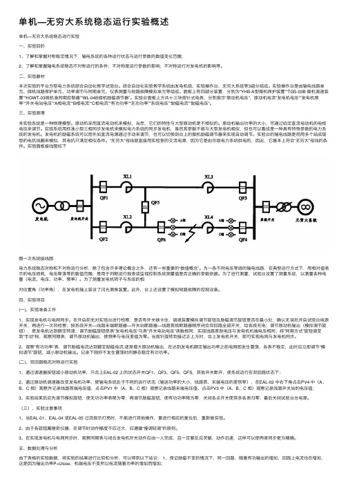
实验⾯板接线图如下图⼀次系统接线图电⼒系统稳态对称和不对称运⾏分析,除了包含许多理论概念之外,还有⼀些重要的“数值概念”。
为⼀条不同电压等级的输电线路,在典型运⾏⽅式下,⽤相对值表⽰的电压损耗,电压降落等的数值范围,是⽤于判断运⾏报表或监视控制系统测量值是否正确的参数依据。
2-D奇异系统无穷远极点与状态响应公式

2-D奇异系统无穷远极点与状态响应公式的报告,800字2-D奇异系统中的无穷远极点与状态响应公式是一种重要的概念,它可以帮助我们了解系统的稳定性。
在本文中,我们将重点讨论2-D奇异系统无穷远极点与状态响应公式,包括状态响应的特点,它的定义以及状态响应公式的推导。
首先,让我们来看看2-D奇异系统中的无穷远极点,它指的是系统的输入和输出在无穷远的情况下的状态。
这种极点可以通过拉普拉斯变换来求得,其表达式为:X(s) = sL(X),其中L(X)代表原始系统的输出变量,而s表示拉普拉斯变换参数。
根据这一表达式,可以推导出无穷远极点的状态响应公式。
其次,我们来看看状态响应的特点。
状态响应可以用来定义系统的输出变量,其标准形式为:X(t)= Ksδ(n),其中Ks代表状态响应参数,δ(n)代表时间延迟,t表示时间。
使用状态响应可以更好地了解系统的响应特性,比如对于稳定系统来说,当输入不变时,系统会保持平衡,而当输入变化时,系统会做出相应的响应。
最后,让我们来看看状态响应公式的推导。
状态响应公式可以使用胡克定理推导,根据胡克定理可以得到公式:X(t) =Ksdi/dt,其中Ks表示状态响应参数,而di/dt表示时间变化率。
根据这一表达式,可以得到状态响应公式:X(t) = Ksδ(n),其中Ks表示状态响应参数,δ(n)表示时间延迟,t表示时间。
综上所述,2-D奇异系统无穷远极点与状态响应公式是重要的概念,可以帮助我们了解系统的稳定性。
我们可以通过拉普拉斯变换来求得无穷远极点,并使用胡克定理来推导出状态响应公式。
虽然了解这些公式可能比较困难,但是正确的使用可以帮助我们更好地实现系统的稳定性。
单机无穷大系统的直接法暂态稳定分析
Vc 作为系统稳定度的定量描述,从而对事故严重
性排队,以便作动态安全分析,实际应用中使用的是规格化的 稳定度 Vn ,通常定义 V Vcr Vc n
2安全 1 ~ 2预警 Vn 0.5 ~ 1警告 0 ~ 0.5严重警告 0潜在危机
Your date here
Your footer here
3
1 总能量 V mv 2 mgh 0 。 2
滚球系统在无扰动时,球位于稳 定平衡点(SEP);受扰后,小球在扰 动结束时位于高度h处 (以SEP为参考 点),并具有速度v,
图1 滚球系统稳定原理
若小球与壁有摩擦力,则受扰 后能量在摩擦力作用下逐步减少; 设小球所在容器的壁高为H (以SEP为 参考点),当小球位于壁沿上,且速 度为零时(即处于不稳定平衡状态), 相应的势能为mgH,称此位置为不 稳定平衡点(UEP),相应的势能为系 统临界能量 Vcr ,即 Vcr m gH
Your footer here
Your date here
V VCr ; 小球最终将滚出容器,而失去稳定性 当 V VCr ; 临界状态 V V ; 在摩擦力作用下,最终静止于SEP。 Cr
对于一个实际系统要解决两个关键问题: 一是对于一个实际系统如何构造一个合理的暂态能量函 数,它的大小应能正确地反映系统失去稳定的严重性; 二是如何确定和系统临界稳定相对应的函数值,即临界 能量,从而可通过对扰动结束时暂态能量函数值和临界 值的比较来判别稳定性。
Vcr
当Vc Vcr ,即图3中面积(A+B)<面积(B+C),则系统 第一摆稳定; 反之若Vc Vcr ,则系统不稳定;
单机无穷大算例系统说明1214

附录一算例系统Ⅰ1.算例系统的数学模型算例系统采用的是文献[1]第12章所使用的单机无穷大系统,图fl-1为其系统单线图。
系统基准频率是60Hz。
下面分别介绍潮流计算和发电机初始状态计算,全部计算基于标幺值。
︒∠0.E~图fl-1 单机无穷大系统单线图1.1.潮流计算已知发电机机端电压幅值为E t=1.0,无穷大母线电压ẼB=0.995∠0°,发电机有功出力P t=0.9,无功出力Q t=0.3。
设δ0为发电机机端电压相角,X∑为发电机端口到无穷大母线之间的电抗之和,则根据下列公式:P t=E t E BX∑sinδ0可得到δ0=sin−1(P t X∑E t E B )=sin−1(0.9×0.651×0.995)=36〫。
1.2.发电机初始状态计算:发电机参数如下表所示:表f-1 发电机参数表由潮流结果可知,发电机定子电流Ĩt=(P+jQ)∗Ẽt∗计算得Ĩt=0.9−j0.31∠−36〫=0.949∠17.57°设δq为发电机q轴相对于无穷大母线电压的角度,机端电压、电流与发电机内电势的关系,如图fl -2所示。
tI dqi d i qtE e d e qt aI R 'QE 'td j I x 'E q E qEd E '图fl -2 同步电机的向量图E Q 是发电机等值电路中一个虚拟的计算用的电势E ̃Q =E ̃t +(R a +jX q )Ĩt 计算得E ̃Q =1∠36〫+(0.003+j1.76)×0.949∠17.57〫=2.204∠81.94°。
也就是说δq =81.94°机端电压E ̃t 的直轴分量和交轴分量:e d =E t sin (δq −δe )=1×sin (81.94°−36°)=0.718e q=E t cos(δq−δe)=1×cos(81.94°−36°)=0.696定子绕组出口电流Ĩt直轴分量和交轴分量i d=I t sin(δq−δe+∅)=0.949sin(81.94°−36°+18.49°)=0.856i q=I t cos(δq−δe+∅)=0.949cos(81.94°−36°+18.49°)=0.411暂态电势的计算公式为Ẽ′=Ẽt+(R a+j X d′)Ĩt得Ẽ′=1∠36〫+(0.003+j0.3)×0.949∠17.57〫=1.125∠49.84°不计发电机的饱和效应,空载电势E q的计算E q=E Q+I d(X d−X q)得E q=2.204+0.856×(1.81−1.76)=2.24681.3.发电机动态模型发电机转子运动方程dΔωdt =1M(T M−T e−K DΔω)dδdt=(ω−1)ω0其中T M------标幺机械转矩T e------标幺电气转矩K D ------机械阻尼转矩系数 ω------转子角速度 P M ---原动机功率 P e ----电磁功率δ--------转子相对于同步旋转参考轴的角位移,单位为电气弧度。
超级计算机:解决复杂问题的利器
超级计算机:解决复杂问题的利器引言当我们面对日益复杂的问题时,人类的智慧和普通计算机的处理能力往往无法胜任。
然而,超级计算机的出现改变了这一现状。
超级计算机以其无与伦比的运算速度和强大的计算能力,成为解决复杂问题的利器。
本文将介绍超级计算机的定义和特点,详细阐述超级计算机在不同领域的应用,并展望未来超级计算机的发展趋势。
超级计算机的定义和特点超级计算机是一种性能远超普通计算机的大型高性能计算机。
它通常由成千上万的处理器节点组成,并配置大量的内存和存储系统。
超级计算机使用并行计算的方式,将大规模的计算任务拆分成小任务,并通过多个处理器同时执行,以提高计算速度。
超级计算机具有以下几个特点:1. 强大的计算能力超级计算机通常拥有非常强大的计算能力。
它们能够迅速执行大规模的数值计算、模拟和分析任务,处理海量的数据,并从中提取有价值的信息。
无论是天气预报、气候模拟、基因组学研究,还是复杂的物理模型和仿真,超级计算机都能够胜任。
2. 高速的运算速度超级计算机以惊人的速度运行着。
其处理器节点以非常高的时钟频率工作,使得计算任务可以以极快的速度完成。
此外,超级计算机还采用了先进的并行计算技术,使得多个处理器能够同时执行任务,进一步提高了计算速度。
这种高速运算的能力使得超级计算机可以在有限的时间内完成大规模的计算任务。
3. 大规模的存储和内存超级计算机通常配备大规模的存储和内存系统。
这些存储和内存可以容纳海量的数据,并确保计算过程中的数据读取和写入速度。
大规模的存储和内存系统对于处理大规模数据、进行复杂计算任务至关重要,超级计算机的出现为处理大数据提供了更好的解决方案。
4. 自动化管理超级计算机通常采用自动化管理系统,以实现对计算任务和资源的有效管理。
通过自动化管理,超级计算机能够实时监控处理器节点的状态,进行任务调度和资源分配,并保障整个计算过程的顺利进行。
这种自动化管理不仅提高了超级计算机的工作效率,还降低了管理成本和人力投入。
最新单机-无穷大系统实验实验报告

最新单机-无穷大系统实验实验报告实验目的:探究无穷大系统在最新单机游戏中的应用效果,评估其对游戏性能、玩家体验和系统稳定性的影响。
实验环境:- 游戏名称:《幻想世界大冒险》- 系统版本:无穷大系统 V5.0- 硬件配置:Intel Core i7-9700K CPU, 16GB RAM, NVIDIA GeForce RTX 2080 GPU- 操作系统:Windows 10 Home 64-bit实验方法:1. 安装无穷大系统 V5.0至游戏开发环境。
2. 在游戏《幻想世界大冒险》中集成无穷大系统,确保系统与游戏引擎的兼容性。
3. 通过无穷大系统对游戏进行性能优化,包括但不限于资源加载、渲染效率和AI算法。
4. 进行多轮游戏测试,记录游戏运行帧率、加载时间、玩家操作响应等关键数据。
5. 收集玩家反馈,评估无穷大系统对游戏体验的改善程度。
6. 分析系统日志,检测无穷大系统对游戏稳定性的影响。
实验结果:1. 集成无穷大系统后,游戏加载时间平均减少30%,玩家进入游戏的速度得到显著提升。
2. 游戏运行帧率在高负载场景下提升了15%,保证了流畅的游戏体验。
3. AI算法优化后,非玩家角色的行为更加自然和智能,增加了游戏的挑战性和趣味性。
4. 玩家反馈显示,游戏的画面质量和操作手感均有所提升,游戏体验整体满意度提高。
5. 系统稳定性测试表明,游戏崩溃次数减少了50%,系统运行更加稳定。
结论:无穷大系统在最新单机游戏《幻想世界大冒险》中的应用是成功的。
它不仅提高了游戏的性能和稳定性,还增强了玩家的游戏体验。
未来,无穷大系统有望成为游戏开发中的标准组件,为玩家带来更加丰富和流畅的游戏世界。
SIMOREG DC Master卷取

sSIMOREG DC Master6RA70 SeriesApplication Center WinderMicroprocessor-Based Converters from 6kW to 1900kW for Variable-Speed DC DrivesEdition 05Edition 0512.02NOTEThis application does not purport to handle or take into account all of the equipment details or versionsor to cover every conceivable operating situation or application. If you require more detailed information, or if special problems occur, which are not handled in enough detail in this document, please contactyour local Siemens office.The contents of this application are not part of an earlier or existing agreement or legal contract and neither do they change it. The actual purchase contract represents the complete liability of the A&D Variable-Speed Drives Group of Siemens AG. The warranty conditions, specified in the contractbetween the two parties, is the only warranty which will be accepted by the A&D Variable-Speed Drives Group. The warranty conditions specified in the contract are neither expanded nor changed by the information provided in the installation instructions.The reproduction, transmission or use of this document or contents is notpermitted without express written authority. Offenders will be liable fordamages. All rights, including rights created by patent grant orregistration of a utility model or design, are reserved.We have checked that the contents of this publication agree with thehardware and software described herein. Nonetheless, differences mightexist and therefore we cannot guarantee that they are completelyidentical. The information given in this publication is reviewed at regularintervals and any corrections that might be necessary are made in thesubsequent printings. Suggestions for improvement are welcome at alltimes.SIMOREG ® is a registered trademark of Siemens Siemens AG 2000 All rights reservedEdition 0301.01Siemens AG3-52SIMOREG DC Master Application Center winderContentsPage1Overview (5)1.1General.........................................................................................................................................51.2Application guidelines....................................................................................................................51.3Application conditions....................................................................................................................51.4Operating modes and functions (6)2Closed-loop control of a winder (7)2.1Criteria for selecting the control method........................................................................................72.2Torque limiting control...................................................................................................................82.2.1Indirect tension control..................................................................................................................82.2.2Direct tension control..................................................................................................................102.3Speed compensation control.......................................................................................................122.3.1Dancer control............................................................................................................................122.3.2v-constant control (winder)..........................................................................................................142.4Control function blocks................................................................................................................152.4.1Stop tension control....................................................................................................................152.4.2Slip core control..........................................................................................................................152.4.3Variable web width......................................................................................................................152.4.4Variable material density.............................................................................................................152.4.5Calculator for the diameter..........................................................................................................152.4.6Gearbox stage............................................................................................................................152.4.7Speed controller adaptation.........................................................................................................162.4.8Tension controller adaptation......................................................................................................162.4.9Web break recognition................................................................................................................162.5Acceleration compensation calculation........................................................................................162.5.1Determination of fixed value inertia.............................................................................................162.5.2Determination of the variable moment of inertia...........................................................................172.5.3Formulas and dimensions (17)3Interfaces (18)3.1Received data from top level control...........................................................................................183.1.1Transmit data to top level control.................................................................................................193.1.2Analog input ................................................................................................................................193.1.3Analog output..............................................................................................................................193.1.4Pulse generator input (19)4Commissioning notes (20)4.1Speed feedback adjustment ........................................................................................................204.2Compensation of friction torque...................................................................................................204.3Compensation of acceleration torque..........................................................................................214.3.1Constant moment of inertia.........................................................................................................214.3.2Variable moment of inertia...........................................................................................................214.4Optimization of speed controller..................................................................................................214.4.1Optimization at minimal diameter.................................................................................................224.4.2Optimization at maximum diameter..............................................................................................224.5Hints for setting parameters (22)Edition 0512.02Page 5Appendix (23)5.1List of freely assignable function blocks used (23)5.2List of settable fixed values used (24)5.3Detailed schematics (24)5.4Parameter list (51)4-52Siemens AGSIMOREG DC Master Application Center Winder12.02Edition 05Siemens AG5-52SIMOREG DC Master Application Center Winder1Overview1.1GeneralCenter winders are drives on which a web is either wound or unwound at a defined tension via the driven winding shaft. Center winders are used in various industrial branches such as, for example, in foil mills,printing presses, coating plants, paper processing machines (rotary cutters, glazing rollers), spoolers on wire drawing and cable machines, textile machines and sheet-metal reels.This application guide shows how to implement a center winder using the freely assignable function blocks available through the option S00. In this case, binary control commands and setpoints are input via Profibus.NOTESOwing to the number and type of function blocks required, it is absolutely essential to use software version V2.0 or higher!Since the winder can operate in the "Drive" and "Brake" modes, the DC Master 6RA70 must be configured for 4Q operation !1.2 Application guidelinesIn principle, this application is suitable for use in all the examples listed in para. 1.1. The user has the advantage that he can individually tailor the existing, highly universal application to suit his plant using BICO technology and without the need for any additional tools.Restrictions to its use may be encountered in the form of resolution problems in "maneuvering" (low speed)on fast-running machines with large winding ratios, or when the permissible limit frequency of the pulse encoder input is exceeded at V max (high speed). Please refer to the feasibility calculation in Section 11.8"Definition of pulse encoder, speed sensing with pulse encoder" of the basic unit operating guide. If the resolution is not high enough, the center winder must be implemented by means of a T400 technology board and associated standard configuration "Center winder SPW420".1.3 Application conditionsThe full range of functions described in this application document will be available for use only if the SIMOREG DC Master is controlled via a higher-level control system (e.g. SIMATIC S7) in combination with an optional interface board (CBP2) and the Profibus.If you wish to implement hardware-based converter control, you must provide (depending on requirements)CUD2 terminal expansions or supplementary board EB1 and/or EB2. In this case, you will also need to change the connections for the binary input commands and/or setpoints.Please see the relevant data sheets for the supplementary board specifications. For instructions on mounting the boards, please see Section 5.3 "Mounting options" in the operating guide.Edition 0512.021.4 Operating modes and functionsThe winder described can operate in several different modes using a variety of functions. Global settings such as♦control method♦direction of winding♦winder or unwinder♦gear box stage♦winding characteristicare selected via the top level control system. Depending on the selection, the requisite parameter settings are automatically made in the SIMOREG device. In the case of machines used to manufacture broad-web products and therefore requiring a variety of control methods, it is possible to choose between several different control modes simply by switching over control bits. There is no need to change any connector or binector links. All you need to do is select the required settings for characteristics, controllers, parameters or optimization runs.If a hardware control is implemented, the required changes can be made using OR function blocks (for details contact schematic 19).The following modes of operation are implemented:♦direct tension control with tensile force sensor♦indirect tension control without tensile force sensor using torque control♦dancer roll / compensating roll position control♦v-constant controlThe following functions are available in these modes:♦inching, maneuvering (to lead the web)♦stop tension♦slip core control♦setting of a variable web width♦setting a variable material density♦calculator for diameter with monotone or not monotone change of diameter♦ 2 gear box stages♦speed controller adaptation♦tension controller adaptation♦web break recognition6-52Siemens AGSIMOREG DC Master Application Center Winder12.02Edition 05Siemens AG7-52SIMOREG DC Master Application Center Winder2Closed-loop control of a winder2.1Criteria for selecting the control methodThe following table lists selection criteria based on empirical values.The maximum possible web velocity is dependent to a large degree on its relation to the web-lead or maneuvering velocity (see also para. 1.2 Application guidelines).Torque limiting control Speed compensation controlControl method Indirect tension control Direct tension controlDancer control v-constant controlDiameter sensing Calculated from web velocity setpoint and winder speed Calculated from web velocity setpoint and winder speed Calculated from web velocity setpoint and winder speed Calculated fromactual web velocityand winder speed Diameter ratio D max /D core Up to approx. 10:1Good compensation of acceleration torque and friction required Up to approx.15:1Good compensation of acceleration torque and friction required Up to approx. 15:1Good compensation of acceleration torque and frictionrequiredUp to approx. 15:1Actual tension sensingNo Yes No No Tension ratio F max /F min Up to approx. 6:1Good compensation of acceleration torque and friction required Up to approx. 20:1Good compensation of acceleration torque and friction requiredVariable only with variable dancerweightTorque ratio M max /M min Up to approx. 30:1Up to approx. 40:1Dependent on quality of actualtension signalWeb velocity Up to 300m/min with good compensation Up to 1000m/min with good compensation Up to 1000m/minwith good compensationUp to 1000m/min Clamping point Required Required Required Not required Web tacho Not required Not required Not required Required Use preferably for Sheet metal,textiles, paper,cabling Paper,thin foils Rubber, cabling,wire,foil, textiles(generally for extensible materials)Sorting rollerEdition 0512.022.2 Torque limiting controlThe basis for this operating principle is the addition (winder) or subtraction (unwinder) of a fixed value = override setpoint (5-10%) to/from the speed setpoint of the speed controller with active tension control and web inserted. Through its connection to the web, the winder reaches one of its torque limits (pos. limit with winder, negative limit with unwinder). The torque limit is obtained from a feedforward control value derived from the tension setpoint, taking into account diameter, friction, moment of inertia and acceleration.The ramp generator for the speed setpoint merely serves to produce the dv/dt signal (ramp-up and ramp-down time should be set to 0).2.2.1 Indirect tension controlMain drive8-52Siemens AGSIMOREG DC Master Application Center Winder12.02Edition 05Siemens AG9-52SIMOREG DC Master Application Center WinderDescription of mode of operation:Input of current diameter using "Set diameter". This can be done only when the drive is switched off.The maneuvering setpoint stretches the web between the winder and main drive (clamping point). Applying the "Tension control ON external" signal allows activation of the tension control (a minimum torque must also be reached) and the override setpoint is switched in. At the same time, the speed controller input is switched from maneuvering over to operating setpoint (winder), or to 0 (unwinder). The drive torque is adjusted to the torque limit specified by the tension control (derived from tension setpoint). A winding hardness characteristic (tension decreases in proportion to increase in diameter) can be activated as the tension setpoint for the winder.The machine can now be started.With every change in velocity, the product of moment of inertia x acceleration is added to the tension feedforward control.The current diameter is calculated continuously from the quotient of web velocity/winder speed. The tension feedforward control value is multiplied by the varying diameter, thus ensuring that the web tension remains constant.A reduced tension (=stop tension) can be injected at standstill. This is calculated as a percentage of the current operating setpoint tension.If the web breaks, the winder accelerates initially by its override setpoint, the unwinder decelerates to its override setpoint (this is negative so the unwinder rotates in the opposite direction). The web break is sensed, on the one hand, by the delayed evaluation of a minimum torque and, on the other, by a comparison of the torque setpoint and actual values. These are identical if the tension control is active because the drive is operating at its torque limit. When the web breaks, the actual torque decreases when the override speed is reached and this setpoint/actual value difference is evaluated after a delay (to allow for temporary deviations) by a limit monitor. The web velocity setpoint is canceled by the speed controller, both the winder and unwinder rotate at their override setpoint in the winding direction. OFF3 is applied after a parameterizable time period.The "Web break" signal can also be specified from an external source (e.g. via light barriers).To ensure that the specified torque produces a material tension as close as possible to the desired value,the acceleration and friction torques must be compensated accurately!Edition 0512.0210-52Siemens AGSIMOREG DC Master Application Center Winder2.2.2 Direct tension controlWinderMain drive(injection of web velocity)Tensile force sensorDescription of mode of operation:Input of current diameter using "Set diameter". This can be done only when the drive is switched off.The maneuvering setpoint stretches the web between the winder and main drive (clamping point). If the tension exceeds a minimum value within a prespecified period, the tension control is automatically activated, the override setpoint switched in and the tension controller enabled along a ramp (if "Tension controller ON external" signal is applied). At the same time, the speed controller input is switched from maneuvering over to operating setpoint. The drive torque is adjusted to the torque limit specified by the tension control (derived from tension setpoint). A winding hardness characteristic (tension decreases in proportion to increase in diameter) can be activated as the tension setpoint for the winder.The tension controller compares the actual tension with the tension setpoint and adds a corresponding compensation signal to the tension feedforward control value.The machine can now be started.With every change in velocity, the product of moment of inertia x acceleration is added to the tension feedforward control value.The current diameter is calculated continuously from the quotient of web velocity/winder speed. The sum of tension feedforward control value + tension controller output is multiplied by the varying diameter, thus ensuring that the web tension remains constant.A reduced tension (=stop tension) can be injected at standstill. This is calculated as a percentage of the current operating setpoint tension.If the web breaks, the winder accelerates by its override setpoint, the unwinder decelerates to its override setpoint (this is negative so the unwinder rotates in the opposite direction). The web break is sensed, on the one hand, by the delayed evaluation of a minimum tension and, on the other, by a comparison of the torque setpoint and actual values. When the web breaks, the actual torque decreases when the override speed is reached and this setpoint/actual value difference is evaluated after a delay (to allow for temporary deviations) by a limit monitor. The web velocity setpoint is canceled by the speed controller, both the winder and unwinder rotate at their override setpoint in the winding direction. OFF3 is applied after a parameterizable time period.The "Web break" signal can also be specified from an external source (e.g. via light barriers).12-52Siemens AG2.3Speed compensation control2.3.1Dancer controlIn this case, a compensation value (magnitude of override 2-10%) is added to the speed controller setpoint.The drive torque limits are always open.Every time the velocity changes, the product of moment of inertia x acceleration is added as a supplementary torque setpoint to the speed controller output.The ramp generator for the speed setpoint merely serves to produce the dv/dt signal (ramp-up and ramp-down time should be set to 0).DancerWinderMain drive(injection of web velocity)Description of mode of operation:Input of current diameter using "Set diameter". This can be done only when the drive is switched off.The maneuvering setpoint stretches the web between the winder and main drive (clamping point), thereby moving the dancer out of its end position. This activates the position control and enables the position controller along a ramp (if "Tension controller ON external" signal is applied); the position controller output forms the supplementary speed setpoint. The dancer moves to its center position (when position setpoint = 0). At the same time, the speed controller input is switched from the maneuvering over to the operating setpoint.The machine can now be started.The current diameter is calculated continuously from the quotient of web velocity/winder speed.The tension in the web is determined solely by the dancer weight. If a tension control function is required, the dancer must be provided with a control device (e.g. pressure cylinder). The tension setpoint is converted to a pressure setpoint in the 6RA70 and made available at an analog output. A winding hardness characteristic (tension decreases in proportion to increase in diameter) can be activated as the tension setpoint for the winder.A reduced tension (=stop tension) can be injected at standstill. This is calculated as a percentage of the current operating setpoint tension.If the web breaks, the dancer moves to its end positions. The dancer position control is disabled and the OFF3 process initiated. It is useful to delay OFF3 on the winder to allow any loose winding material to be reeled up.NOTEIt may be necessary to activate the D-action component in the actual-value channel for the position controller. This helps to dampen the dancer roller and prevents build-up of oscillation between the dancer and winder.14-52Siemens AG2.3.2 v-constant control (winder)The three control methods described above each require a clamping point on the machine, e.g. in the form of a pair of contacting rollers through which the web is fed and from which the winder receives the web velocity setpoint. If there is no clamping point on the machine, the winder must be regulated to a constant peripheral speed. This necessitates sensing the web velocity using a web tacho so that the diameter can be calculated from v/n.Since the winder is acting quasi as a "main drive" in this instance, the ramp generator must be used to ramp the speed setpoint.Web tachoWinder (v-constant)UnwinderDescription of mode of operation:Input of current diameter using "Set diameter". This can be done only when the drive is switched off.The machine can be started when the web is tensioned.Web-break sensing is not operative in v-constant control mode. If the web breaks, the web tacho signal switches to 0. The calculated diameter would then integrate in direction D min, resulting in a corresponding increase in the winder speed. To prevent this from happening, the "monotone" setting of the diameter calculator must be activated, i.e. the diameter can only increase for the winder and thus remains constant if the web breaks.NOTEWhen the v-constant control method is used, the web velocity must be measured using a web tacho. This also necessitates use of supplementary board SBP pulse encoder evaluation (second actual tacho value).2.4 Control function blocks2.4.1 Stop tension controlThe stop tension is injected as a function of the external control and the internal n=0 message. It can be parameterized as a percentage of the set operating tension. If a constant stop tension is required, parameter U151.01 must be connected to K0001.2.4.2 Slip core controlThe coil hardness influences, in conjunction with the diameter, the tension setpoint according to an adjustable characteristic. The setpoints can be taken either from an internal characteristic block or externally from the bus. Depending on the application, 5 additional characteristics are available. It is meaningful to work without the slip core control if an unwinder is used. Switching between different characteristics is implemented via external control.2.4.3 Variable web widthThe selection of different web widths is automatically taken into account for the calculation of the moment of inertia and therefore also for the resulting feedforward control torque. In this case, the maximum web width must always be assumed to be 100%. If a fixed web width is required, parameter U150.03 must be connected to K0001.2.4.4 Variable material densityThe selection of different material densities is automatically taken into account for the calculation of the moment of inertia and therefore also for the resulting feedforward control torque. In this case, the maximum material density must always be assumed to be 100%. If a variable material density input is not required, parameter U525.04 must be connected to K0001.2.4.5 Calculator for the diameterThe diameter calculator calculates the current diameter from the web velocity setpoint (or actual web velocity with V-constant control method) and the winder speed. This calculation is only performed if there is a frictional connection to the continuous material, the tension controller is turned on and the system is in the run state. Since the diameter can only decrease on an unwinder, and increase on a winder, calculation in the opposite direction is disabled ("monotone" setting for diameter change).If the user wishes to alter this behavior, he can enable the diameter calculator to work in both directions by changing parameter P421 from 1 to 0.2.4.6 Gearbox stageThe selection of gear stage 2 is automatically taken into account in the calculation of the moment of inertia and the resulting feedforward control torque. The lower gear ratio must always be assumed to be 100%.16-52Siemens AG2.4.7Speed controller adaptationThe proportional gain and reset time of the speed controller can be adapted as a function of moment ofinertia. An optimization process is used to determine the values at minimum and maximum winding diameters and linear interpolation performed between them.2.4.8Tension controller adaptationThe proportional gain of the tension controller can be adapted as a function of moment of inertia.2.4.9Web break recognitionIf the tension control is turned on, the web break recognition is enabled.Direct tension control:Triggering results if selectable torque variance is exceeded and torque drops below minimum tension.Indirect tension control:Triggering results if selectable torque variance is exceeded and torque dropsbelow selectable minimum.Compensating roll:Triggering results if instantaneous value exceeds selectable position value.If web tear recognition is triggered, speed setpoint is set 0 and the calculation for the diameter is disabled.The unwinder turns backwards, the winder forward, both using their bias. If a compensating (dancer) roll control is used, the position controller reaches its limit due to the missing instantaneous value. The bias results from the set intervention. After a selectable time , "Off 3“ is triggered.2.5 Acceleration compensation calculationIn order to ensure a constant tension torque during acceleration and deceleration, the armature current should be pre controlled using the required torque. The moment of inertia is never a constant value due to the steady change of the diameter of the winder.♦ Fixed inertia J F (adjustable using P407)♦ Variable moment of inertia J V (is calculated using building block 116, and is influenced by web width(K3008) and material density K3009)Chapter 4 contains instructions on how to calculate the two torques using available system data.2.5.1Determination of fixed value inertiaThe fixed moment of inertia is the sum of the following moment of inertia ♦ moment of inertia of motors♦ moment of inertia of gear corresponding to the shaft of the motor ♦ moment of inertia of winder core corresponding to the motor shaft ♦additional moments of inertia such as couplersFormula:2Core Gear Motor F i J J J J ++=For motor or gear values please refer to the datasheet or type plate. The inertia of the winder core has to be calculated. (Contact formula for the calculation of moment of inertia for solid cylinder or hollow cylinder.).If the winder's core mass is relatively small, or the gear ratio rather large, the moment of inertia can be considered irrelevant.。
超级计算技术的基本原理与概念

超级计算技术的基本原理与概念超级计算技术是一种高度先进的计算能力,用于解决科学、工程、商业和社会问题中存在的复杂性。
它使用一组强大的计算机资源,以极高的处理速度和大规模的数据存储能力,进行高度并行的计算。
超级计算机的基本原理是并行计算。
并行计算是将一个计算任务分解为多个子任务,并使用多个计算资源同时执行这些子任务。
这种并行性使得超级计算机可以以前所未有的速度处理大规模或高复杂度的问题。
超级计算机采用的并行计算技术主要分为两种:共享内存和分布式计算。
共享内存是一种计算资源协同工作的方式。
在共享内存架构中,所有处理器共享同一个集中式的内存系统。
这意味着每个处理器都可以直接访问任何其他处理器的内存。
共享内存架构具有内存一致性和线程同步的优势,但也存在并发控制和性能瓶颈的挑战。
另一种并行计算技术是分布式计算。
在分布式计算中,计算资源分布在多台计算机上,通过网络连接进行通信和协同工作。
每台计算机都有自己的本地内存,计算任务在各个计算节点上分布并执行。
分布式计算架构具有可伸缩性和容错性的优势,但也需要高效的通信机制和任务调度算法。
超级计算技术的关键概念之一是并行算法。
并行算法是为了能够在超级计算机上高效执行而设计的算法。
与传统的串行算法不同,这些算法将问题分解为多个子问题,并使用并行计算的方式同时解决这些子问题。
并行算法需要考虑任务分配、通信开销、负载平衡等因素,以提高计算效率。
超级计算还涉及到大规模数据处理的技术。
现代科学和工程应用产生了海量的数据,如气象数据、基因组数据、地震数据等。
超级计算技术通过使用高性能的存储系统和数据处理技术,能够高效地存储、管理和分析这些大规模数据。
超级计算技术的发展也受到硬件的制约。
超级计算机通常由大量的处理器、内存和存储单元组成。
高性能的处理器、高速的通信网络和大容量的存储系统是实现超级计算性能的关键。
硬件的不断创新和进步推动了超级计算技术的发展。
总之,超级计算技术是一种强大的计算能力,具有高度并行性、大规模数据处理和高速计算的特点。
Native Instruments MASCHINE MK3 用户手册说明书
The information in this document is subject to change without notice and does not represent a commitment on the part of Native Instruments GmbH. The software described by this docu-ment is subject to a License Agreement and may not be copied to other media. No part of this publication may be copied, reproduced or otherwise transmitted or recorded, for any purpose, without prior written permission by Native Instruments GmbH, hereinafter referred to as Native Instruments.“Native Instruments”, “NI” and associated logos are (registered) trademarks of Native Instru-ments GmbH.ASIO, VST, HALion and Cubase are registered trademarks of Steinberg Media Technologies GmbH.All other product and company names are trademarks™ or registered® trademarks of their re-spective holders. Use of them does not imply any affiliation with or endorsement by them.Document authored by: David Gover and Nico Sidi.Software version: 2.6.11 (11/2017)Hardware version: MASCHINE MK3Special thanks to the Beta Test Team, who were invaluable not just in tracking down bugs, but in making this a better product.NATIVE INSTRUMENTS GmbH Schlesische Str. 29-30D-10997 Berlin Germanywww.native-instruments.de NATIVE INSTRUMENTS North America, Inc. 6725 Sunset Boulevard5th FloorLos Angeles, CA 90028USANATIVE INSTRUMENTS K.K.YO Building 3FJingumae 6-7-15, Shibuya-ku, Tokyo 150-0001Japanwww.native-instruments.co.jp NATIVE INSTRUMENTS UK Limited 18 Phipp StreetLondon EC2A 4NUUKNATIVE INSTRUMENTS FRANCE SARL 113 Rue Saint-Maur75011 ParisFrance SHENZHEN NATIVE INSTRUMENTS COMPANY Limited 203B & 201B, Nanshan E-Commerce Base Of Innovative ServicesShi Yun Road, Shekou, Nanshan, Shenzhen China© NATIVE INSTRUMENTS GmbH, 2017. All rights reserved.Table of Contents1Welcome to MASCHINE (23)1.1MASCHINE Documentation (24)1.2Document Conventions (25)1.3New Features in MASCHINE 2.6.11 (27)2Basic Concepts (29)2.1Important Names and Concepts (29)2.2Adjusting the MASCHINE User Interface (32)2.2.1Adjusting the Size of the Interface (32)2.2.2Switching between Ideas View and Arranger View (33)2.2.3Showing/Hiding the Browser (34)2.2.4Minimizing the Mixer (34)2.2.5Showing/Hiding the Control Lane (35)2.3Common Operations (36)2.3.1Using the 4-Directional Push Encoder (36)2.3.2Pinning a Mode on the Controller (37)2.3.3Pinning a Mode on the Controller (38)2.3.4Undo/Redo (39)2.3.5List Overlay for Selectors (41)2.3.6Zoom and Scroll Overlays (42)2.3.7Focusing on a Group or a Sound (42)2.3.8Switching Between the Master, Group, and Sound Level (47)2.3.9Navigating Channel Properties, Plug-ins, and Parameter Pages in the Control Area.482.3.9.1Extended Navigate Mode on Your Controller (53)2.3.10Using Two or More Hardware Controllers (56)2.3.11Touch Auto-Write Option (58)2.4Native Kontrol Standard (60)2.5Stand-Alone and Plug-in Mode (62)2.5.1Differences between Stand-Alone and Plug-in Mode (62)2.5.2Switching Instances (63)2.5.3Controlling Various Instances with Different Controllers (64)2.6Preferences (65)2.6.1Preferences – General Page (66)2.6.2Preferences – Audio Page (70)2.6.3Preferences – MIDI Page (74)2.6.4Preferences – Default Page (77)2.6.5Preferences – Library Page (81)2.6.6Preferences – Plug-ins Page (89)2.6.7Preferences – Hardware Page (94)2.6.8Preferences – Colors Page (98)2.7Integrating MASCHINE into a MIDI Setup (100)2.7.1Connecting External MIDI Equipment (100)2.7.2Sync to External MIDI Clock (101)2.7.3Send MIDI Clock (102)2.8Syncing MASCHINE using Ableton Link (103)2.8.1Connecting to a Network (103)2.8.2Joining and Leaving a Link Session (103)2.9Using a Pedal with the MASCHINE Controller (105)2.10File Management on the MASCHINE Controller (105)3Browser (107)3.1Browser Basics (107)3.1.1The MASCHINE Library (107)3.1.2Browsing the Library vs. Browsing Your Hard Disks (108)3.2Searching and Loading Files from the Library (109)3.2.1Overview of the LIBRARY Pane (109)3.2.2Selecting or Loading a Product and Selecting a Bank from the Browser (114)3.2.2.1Browsing by Product Category Using MASCHINE MK3 (118)3.2.2.2Browsing by Product Vendor Using MASCHINE MK3 (119)3.2.3Selecting a Product Category, a Product, a Bank, and a Sub-Bank (119)3.2.3.1Selecting a Product Category, a Product, a Bank, and a Sub-Bank on theController (124)3.2.4Selecting a File Type (125)3.2.5Choosing Between Factory and User Content (126)3.2.6Selecting Type and Mode Tags (127)3.2.7List and Tag Overlays in the Browser (133)3.2.8Performing a Text Search (135)3.2.9Loading a File from the Result List (135)3.3Additional Browsing Tools (140)3.3.1Loading the Selected Files Automatically (140)3.3.2Auditioning Instrument Presets (142)3.3.3Auditioning Samples (143)3.3.4Loading Groups with Patterns (144)3.3.5Loading Groups with Routing (145)3.3.6Displaying File Information (145)3.4Using Favorites in the Browser (146)3.5Editing the Files’ Tags and Properties (152)3.5.1Attribute Editor Basics (152)3.5.2The BANK Page (154)3.5.3The TYPES and MODES Pages (155)3.5.4The PROPERTIES Page (157)3.6Loading and Importing Files from Your File System (158)3.6.1Overview of the FILES Pane (158)3.6.2Using Favorites (160)3.6.3Using the Location Bar (161)3.6.4Navigating to Recent Locations (162)3.6.5Using the Result List (163)3.6.6Importing Files to the MASCHINE Library (166)3.7Locating Missing Samples (168)3.8Using Quick Browse (170)4Managing Sounds, Groups, and Your Project (175)4.1Overview of the Sounds, Groups, and Master (175)4.1.1The Sound, Group, and Master Channels (176)4.1.2Similarities and Differences in Handling Sounds and Groups (177)4.1.3Selecting Multiple Sounds or Groups (178)4.2Managing Sounds (183)4.2.1Loading Sounds (185)4.2.2Pre-listening to Sounds (186)4.2.3Renaming Sound Slots (187)4.2.4Changing the Sound’s Color (187)4.2.5Saving Sounds (189)4.2.6Copying and Pasting Sounds (191)4.2.7Moving Sounds (194)4.2.8Resetting Sound Slots (196)4.3Managing Groups (197)4.3.1Creating Groups (198)4.3.2Loading Groups (200)4.3.3Renaming Groups (201)4.3.4Changing the Group’s Color (201)4.3.5Saving Groups (203)4.3.6Copying and Pasting Groups (205)4.3.7Reordering Groups (208)4.3.8Deleting Groups (209)4.4Exporting MASCHINE Objects and Audio (210)4.4.1Saving a Group with its Samples (211)4.4.2Saving a Project with its Samples (212)4.4.3Exporting Audio (214)4.5Importing Third-Party File Formats (221)4.5.1Loading REX Files into Sound Slots (221)4.5.2Importing MPC Programs to Groups (222)5Playing on the Controller (226)5.1Adjusting the Pads (226)5.1.1The Pad View in the Software (226)5.1.2Choosing a Pad Input Mode (228)5.1.3Adjusting the Base Key (231)5.1.4Using Choke Groups (233)5.1.5Using Link Groups (235)5.2Adjusting the Key, Choke, and Link Parameters for Multiple Sounds (238)5.3Adjusting the Base Key (239)5.4Playing Tools (240)5.4.1Mute and Solo (241)5.4.2Choke All Notes (245)5.4.3Groove (246)5.4.4Level, Tempo, Tune, and Groove Shortcuts on Your Controller (248)5.4.5Tap Tempo (252)5.5Performance Features (253)5.5.1Overview of the Perform Features (253)5.5.2Selecting a Scale and Creating Chords (256)5.5.3Scale and Chord Parameters (256)5.5.4Creating Arpeggios and Repeated Notes (262)5.5.5Swing on Note Repeat / Arp Output (267)5.6Using Lock Snapshots (268)5.6.1Creating a Lock Snapshot (268)5.6.2Using Extended Lock (269)5.6.3Updating a Lock Snapshot (269)5.6.4Recalling a Lock Snapshot (270)5.6.5Morphing Between Lock Snapshots (270)5.6.6Deleting a Lock Snapshot (271)5.6.7Triggering Lock Snapshots via MIDI (272)5.7Using the Smart Strip (274)5.7.1Pitch Mode (274)5.7.2Modulation Mode (275)5.7.3Perform Mode (275)5.7.4Notes Mode (276)6Working with Plug-ins (277)6.1Plug-in Overview (277)6.1.1Plug-in Basics (277)6.1.2First Plug-in Slot of Sounds: Choosing the Sound’s Role (281)6.1.3Loading, Removing, and Replacing a Plug-in (281)6.1.3.1Browser Plug-in Slot Selection (287)6.1.4Adjusting the Plug-in Parameters (290)6.1.5Bypassing Plug-in Slots (290)6.1.6Using Side-Chain (292)6.1.7Moving Plug-ins (292)6.1.8Alternative: the Plug-in Strip (294)6.1.9Saving and Recalling Plug-in Presets (294)6.1.9.1Saving Plug-in Presets (295)6.1.9.2Recalling Plug-in Presets (296)6.1.9.3Removing a Default Plug-in Preset (297)6.2The Sampler Plug-in (298)6.2.1Page 1: Voice Settings / Engine (300)6.2.2Page 2: Pitch / Envelope (302)6.2.3Page 3: FX / Filter (305)6.2.4Page 4: Modulation (307)6.2.5Page 5: LFO (309)6.2.6Page 6: Velocity / Modwheel (311)6.3Using Native Instruments and External Plug-ins (313)6.3.1Opening/Closing Plug-in Windows (313)6.3.2Using the VST/AU Plug-in Parameters (316)6.3.3Setting Up Your Own Parameter Pages (317)6.3.4Using VST/AU Plug-in Presets (322)6.3.5Multiple-Output Plug-ins and Multitimbral Plug-ins (325)7Working with Patterns (326)7.1Pattern Basics (326)7.1.1Pattern Editor Overview (327)7.1.2Navigating the Event Area (333)7.1.3Following the Playback Position in the Pattern (335)7.1.4Jumping to Another Playback Position in the Pattern (337)7.1.5Group View and Keyboard View (338)7.1.6Adjusting the Arrange Grid and the Pattern Length (341)7.1.7Adjusting the Step Grid and the Nudge Grid (344)7.2Recording Patterns in Real Time (349)7.2.1Recording Your Patterns Live (349)7.2.2The Record Prepare Mode (352)7.2.3Using the Metronome (353)7.2.4Recording with Count-in (354)7.2.5Quantizing while Recording (356)7.3Recording Patterns with the Step Sequencer (356)7.3.1Step Mode Basics (356)7.3.2Editing Events in Step Mode (359)7.3.3Recording Modulation in Step Mode (361)7.4Editing Events (361)7.4.1Editing Events with the Mouse: an Overview (362)7.4.2Creating Events/Notes (365)7.4.3Selecting Events/Notes (366)7.4.4Editing Selected Events/Notes (372)7.4.5Deleting Events/Notes (378)7.4.6Cut, Copy, and Paste Events/Notes (381)7.4.7Quantizing Events/Notes (383)7.4.8Quantization While Playing (385)7.4.9Doubling a Pattern (386)7.4.10Adding Variation to Patterns (387)7.5Recording and Editing Modulation (391)7.5.1Which Parameters Are Modulatable? (392)7.5.2Recording Modulation (393)7.5.3Creating and Editing Modulation in the Control Lane (395)7.6Creating MIDI Tracks from Scratch in MASCHINE (401)7.7Managing Patterns (403)7.7.1The Pattern Manager and Pattern Mode (403)7.7.2Selecting Patterns and Pattern Banks (406)7.7.3Creating Patterns (408)7.7.4Deleting Patterns (410)7.7.5Creating and Deleting Pattern Banks (411)7.7.6Naming Patterns (413)7.7.7Changing the Pattern’s Color (415)7.7.8Duplicating, Copying, and Pasting Patterns (416)7.7.9Moving Patterns (419)7.7.10Adjusting Pattern Length in Fine Increments (420)7.8Importing/Exporting Audio and MIDI to/from Patterns (421)7.8.1Exporting Audio from Patterns (421)7.8.2Exporting MIDI from Patterns (422)7.8.3Importing MIDI to Patterns (425)8Audio Routing, Remote Control, and Macro Controls (434)8.1Audio Routing in MASCHINE (435)8.1.1Sending External Audio to Sounds (436)8.1.2Configuring the Main Output of Sounds and Groups (441)8.1.3Setting Up Auxiliary Outputs for Sounds and Groups (446)8.1.4Configuring the Master and Cue Outputs of MASCHINE (450)8.1.5Mono Audio Inputs (456)8.1.5.1Configuring External Inputs for Sounds in Mix View (457)8.2Using MIDI Control and Host Automation (461)8.2.1Triggering Sounds via MIDI Notes (462)8.2.2Triggering Scenes via MIDI (469)8.2.3Controlling Parameters via MIDI and Host Automation (471)8.2.4Selecting VST/AU Plug-in Presets via MIDI Program Change (479)8.2.5Sending MIDI from Sounds (480)8.3Creating Custom Sets of Parameters with the Macro Controls (484)8.3.1Macro Control Overview (485)8.3.2Assigning Macro Controls Using the Software (486)8.3.3Assigning Macro Controls Using the Controller (492)9Controlling Your Mix (494)9.1Mix View Basics (494)9.1.1Switching between Arrange View and Mix View (494)9.1.2Mix View Elements (495)9.2The Mixer (497)9.2.1Displaying Groups vs. Displaying Sounds (498)9.2.2Adjusting the Mixer Layout (500)9.2.3Selecting Channel Strips (501)9.2.4Managing Your Channels in the Mixer (502)9.2.5Adjusting Settings in the Channel Strips (504)9.2.6Using the Cue Bus (508)9.3The Plug-in Chain (510)9.4The Plug-in Strip (511)9.4.1The Plug-in Header (513)9.4.2Panels for Drumsynths and Internal Effects (515)9.4.3Panel for the Sampler (516)9.4.4Custom Panels for Native Instruments Plug-ins (519)9.4.5Undocking a Plug-in Panel (Native Instruments and External Plug-ins Only) (523)9.5Controlling Your Mix from the Controller (525)9.5.1Navigating Your Channels in Mix Mode (526)9.5.2Adjusting the Level and Pan in Mix Mode (527)9.5.3Mute and Solo in Mix Mode (528)9.5.4Plug-in Icons in Mix Mode (528)10Using the Drumsynths (529)10.1Drumsynths – General Handling (530)10.1.1Engines: Many Different Drums per Drumsynth (530)10.1.2Common Parameter Organization (530)10.1.3Shared Parameters (533)10.1.4Various Velocity Responses (533)10.1.5Pitch Range, Tuning, and MIDI Notes (533)10.2The Kicks (534)10.2.1Kick – Sub (536)10.2.2Kick – Tronic (538)10.2.3Kick – Dusty (541)10.2.4Kick – Grit (542)10.2.5Kick – Rasper (545)10.2.6Kick – Snappy (546)10.2.7Kick – Bold (548)10.2.8Kick – Maple (550)10.2.9Kick – Push (551)10.3The Snares (553)10.3.1Snare – Volt (555)10.3.2Snare – Bit (557)10.3.3Snare – Pow (559)10.3.4Snare – Sharp (560)10.3.5Snare – Airy (562)10.3.6Snare – Vintage (564)10.3.7Snare – Chrome (566)10.3.8Snare – Iron (568)10.3.9Snare – Clap (570)10.3.10Snare – Breaker (572)10.4The Hi-hats (574)10.4.1Hi-hat – Silver (575)10.4.2Hi-hat – Circuit (577)10.4.3Hi-hat – Memory (579)10.4.4Hi-hat – Hybrid (581)10.4.5Creating a Pattern with Closed and Open Hi-hats (583)10.5The Toms (584)10.5.1Tom – Tronic (586)10.5.2Tom – Fractal (588)10.5.3Tom – Floor (592)10.5.4Tom – High (594)10.6The Percussions (595)10.6.1Percussion – Fractal (597)10.6.2Percussion – Kettle (600)10.6.3Percussion – Shaker (602)10.7The Cymbals (606)10.7.1Cymbal – Crash (608)10.7.2Cymbal – Ride (610)11Using the Bass Synth (613)11.1Bass Synth – General Handling (614)11.1.1Parameter Organization (614)11.1.2Bass Synth Parameters (616)12Using Effects (618)12.1Applying Effects to a Sound, a Group or the Master (618)12.1.1Adding an Effect (618)12.1.2Other Operations on Effects (627)12.1.3Using the Side-Chain Input (629)12.2Applying Effects to External Audio (632)12.2.1Step 1: Configure MASCHINE Audio Inputs (632)12.2.2Step 2: Set up a Sound to Receive the External Input (635)12.2.3Step 3: Load an Effect to Process an Input (637)12.3Creating a Send Effect (639)12.3.1Step 1: Set Up a Sound or Group as Send Effect (639)12.3.2Step 2: Route Audio to the Send Effect (644)12.3.3 A Few Notes on Send Effects (646)12.4Creating Multi-Effects (647)13Effect Reference (650)13.1Dynamics (651)13.1.1Compressor (651)13.1.2Gate (655)13.1.3Transient Master (659)13.1.4Limiter (661)13.1.5Maximizer (665)13.2Filtering Effects (668)13.2.1EQ (668)13.2.2Filter (671)13.2.3Cabinet (675)13.3Modulation Effects (676)13.3.1Chorus (676)13.3.2Flanger (678)13.3.3FM (680)13.3.4Freq Shifter (681)13.3.5Phaser (683)13.4Spatial and Reverb Effects (685)13.4.1Ice (685)13.4.2Metaverb (687)13.4.3Reflex (688)13.4.4Reverb (Legacy) (690)13.4.5Reverb (692)13.4.5.1Reverb Room (692)13.4.5.2Reverb Hall (695)13.4.5.3Plate Reverb (698)13.5Delays (700)13.5.1Beat Delay (700)13.5.2Grain Delay (703)13.5.3Grain Stretch (705)13.5.4Resochord (707)13.6Distortion Effects (709)13.6.1Distortion (709)13.6.2Lofi (711)13.6.3Saturator (713)13.6.4Analog Distortion (716)13.7Perform FX (718)13.7.1Filter (719)13.7.2Flanger (721)13.7.3Burst Echo (724)13.7.4Reso Echo (726)13.7.5Ring (729)13.7.6Stutter (731)13.7.7Tremolo (734)13.7.8Scratcher (737)14Working with the Arranger (740)14.1Arranger Basics (740)14.1.1Navigating the Arranger (743)14.1.2Following the Playback Position in Your Project (745)14.1.3Jumping to Other Sections (746)14.2Using Ideas View (748)14.2.1Scene Overview (748)14.2.2Creating Scenes (750)14.2.3Assigning and Removing Patterns (751)14.2.4Selecting Scenes (755)14.2.5Deleting Scenes (757)14.2.6Creating and Deleting Scene Banks (758)14.2.7Clearing Scenes (759)14.2.8Duplicating Scenes (759)14.2.9Reordering Scenes (761)14.2.10Making Scenes Unique (762)14.2.11Appending Scenes to Arrangement (763)14.2.12Naming Scenes (764)14.2.13Changing the Color of a Scene (765)14.3Using Arranger View (767)14.3.1Section Management Overview (767)14.3.2Creating Sections (772)14.3.3Assigning a Scene to a Section (773)14.3.4Selecting Sections and Section Banks (774)14.3.5Reorganizing Sections (778)14.3.6Adjusting the Length of a Section (779)14.3.6.1Adjusting the Length of a Section Using the Software (781)14.3.6.2Adjusting the Length of a Section Using the Controller (782)14.3.7Assigning and Removing Patterns (783)14.3.8Duplicating Sections (785)14.3.8.1Making Sections Unique (786)14.3.9Removing Sections (787)14.3.10Renaming Scenes (789)14.3.11Clearing Sections (790)14.3.12Creating and Deleting Section Banks (791)14.3.13Enabling Auto Length (792)14.3.14Looping (793)14.3.14.1Setting the Loop Range in the Software (793)14.4Playing with Sections (794)14.4.1Jumping to another Playback Position in Your Project (795)14.5Triggering Sections or Scenes via MIDI (796)14.6The Arrange Grid (798)14.7Quick Grid (800)15Sampling and Sample Mapping (801)15.1Opening the Sample Editor (801)15.2Recording a Sample (802)15.2.1Opening the Record Page (802)15.2.2Selecting the Source and the Recording Mode (803)15.2.3Arming, Starting, and Stopping the Recording (806)15.2.5Checking Your Recordings (810)15.2.6Location and Name of Your Recorded Samples (813)15.3Editing a Sample (814)15.3.1Using the Edit Page (814)15.3.2Audio Editing Functions (820)15.4Slicing a Sample (828)15.4.1Opening the Slice Page (829)15.4.2Adjusting the Slicing Settings (830)15.4.3Live Slicing (836)15.4.3.1Live Slicing Using the Controller (836)15.4.3.2Delete All Slices (837)15.4.4Manually Adjusting Your Slices (837)15.4.5Applying the Slicing (844)15.5Mapping Samples to Zones (850)15.5.1Opening the Zone Page (850)15.5.2Zone Page Overview (851)15.5.3Selecting and Managing Zones in the Zone List (853)15.5.4Selecting and Editing Zones in the Map View (858)15.5.5Editing Zones in the Sample View (862)15.5.6Adjusting the Zone Settings (865)15.5.7Adding Samples to the Sample Map (872)16Appendix: Tips for Playing Live (875)16.1Preparations (875)16.1.1Focus on the Hardware (875)16.1.2Customize the Pads of the Hardware (875)16.1.3Check Your CPU Power Before Playing (875)16.1.4Name and Color Your Groups, Patterns, Sounds and Scenes (876)16.1.5Consider Using a Limiter on Your Master (876)16.1.6Hook Up Your Other Gear and Sync It with MIDI Clock (876)16.1.7Improvise (876)16.2Basic Techniques (876)16.2.1Use Mute and Solo (876)16.2.2Use Scene Mode and Tweak the Loop Range (877)16.2.3Create Variations of Your Drum Patterns in the Step Sequencer (877)16.2.4Use Note Repeat (877)16.2.5Set Up Your Own Multi-effect Groups and Automate Them (877)16.3Special Tricks (878)16.3.1Changing Pattern Length for Variation (878)16.3.2Using Loops to Cycle Through Samples (878)16.3.3Using Loops to Cycle Through Samples (878)16.3.4Load Long Audio Files and Play with the Start Point (878)17Troubleshooting (879)17.1Knowledge Base (879)17.2Technical Support (879)17.3Registration Support (880)17.4User Forum (880)18Glossary (881)Index (889)1Welcome to MASCHINEThank you for buying MASCHINE!MASCHINE is a groove production studio that implements the familiar working style of classi-cal groove boxes along with the advantages of a computer based system. MASCHINE is ideal for making music live, as well as in the studio. It’s the hands-on aspect of a dedicated instru-ment, the MASCHINE hardware controller, united with the advanced editing features of the MASCHINE software.Creating beats is often not very intuitive with a computer, but using the MASCHINE hardware controller to do it makes it easy and fun. You can tap in freely with the pads or use Note Re-peat to jam along. Alternatively, build your beats using the step sequencer just as in classic drum machines.Patterns can be intuitively combined and rearranged on the fly to form larger ideas. You can try out several different versions of a song without ever having to stop the music.Since you can integrate it into any sequencer that supports VST, AU, or AAX plug-ins, you can reap the benefits in almost any software setup, or use it as a stand-alone application. You can sample your own material, slice loops and rearrange them easily.However, MASCHINE is a lot more than an ordinary groovebox or sampler: it comes with an inspiring 7-gigabyte library, and a sophisticated, yet easy to use tag-based Browser to give you instant access to the sounds you are looking for.What’s more, MASCHINE provides lots of options for manipulating your sounds via internal ef-fects and other sound-shaping possibilities. You can also control external MIDI hardware and 3rd-party software with the MASCHINE hardware controller, while customizing the functions of the pads, knobs and buttons according to your needs utilizing the included Controller Editor application. We hope you enjoy this fantastic instrument as much as we do. Now let’s get go-ing!—The MASCHINE team at Native Instruments.MASCHINE Documentation1.1MASCHINE DocumentationNative Instruments provide many information sources regarding MASCHINE. The main docu-ments should be read in the following sequence:1.MASCHINE Getting Started: This document provides a practical approach to MASCHINE viaa set of tutorials covering easy and more advanced tasks in order to help you familiarizeyourself with MASCHINE.2.MASCHINE Manual (this document): The MASCHINE Manual provides you with a compre-hensive description of all MASCHINE software and hardware features.Additional documentation sources provide you with details on more specific topics:▪Controller Editor Manual: Besides using your MASCHINE hardware controller together withits dedicated MASCHINE software, you can also use it as a powerful and highly versatileMIDI controller to pilot any other MIDI-capable application or device. This is made possibleby the Controller Editor software, an application that allows you to precisely define all MIDIassignments for your MASCHINE controller. The Controller Editor was installed during theMASCHINE installation procedure. For more information on this, please refer to the Con-troller Editor Manual available as a PDF file via the Help menu of Controller Editor.▪Online Support Videos: You can find a number of support videos on The Official Native In-struments Support Channel under the following URL: https:///NIsupport-EN We recommend that you follow along with these instructions while the respective appli-cation is running on your computer.Other Online Resources:If you are experiencing problems related to your Native Instruments product that the supplied documentation does not cover, there are several ways of getting help:▪Knowledge Base▪User Forum▪Technical Support▪Registration SupportYou will find more information on these subjects in the chapter Troubleshooting.1.2Document ConventionsThis section introduces you to the signage and text highlighting used in this manual. This man-ual uses particular formatting to point out special facts and to warn you of potential issues. The icons introducing these notes let you see what kind of information is to be expected:This document uses particular formatting to point out special facts and to warn you of poten-tial issues. The icons introducing the following notes let you see what kind of information can be expected:Furthermore, the following formatting is used:▪Text appearing in (drop-down) menus (such as Open…, Save as… etc.) in the software and paths to locations on your hard disk or other storage devices is printed in italics.▪Text appearing elsewhere (labels of buttons, controls, text next to checkboxes etc.) in the software is printed in blue. Whenever you see this formatting applied, you will find the same text appearing somewhere on the screen.▪Text appearing on the displays of the controller is printed in light grey. Whenever you see this formatting applied, you will find the same text on a controller display.▪Text appearing on labels of the hardware controller is printed in orange. Whenever you see this formatting applied, you will find the same text on the controller.▪Important names and concepts are printed in bold.▪References to keys on your computer’s keyboard you’ll find put in square brackets (e.g.,“Press [Shift] + [Enter]”).►Single instructions are introduced by this play button type arrow.→Results of actions are introduced by this smaller arrow.Naming ConventionThroughout the documentation we will refer to MASCHINE controller (or just controller) as the hardware controller and MASCHINE software as the software installed on your computer.The term “effect” will sometimes be abbreviated as “FX” when referring to elements in the MA-SCHINE software and hardware. These terms have the same meaning.Button Combinations and Shortcuts on Your ControllerMost instructions will use the “+” sign to indicate buttons (or buttons and pads) that must be pressed simultaneously, starting with the button indicated first. E.g., an instruction such as:“Press SHIFT + PLAY”means:1.Press and hold SHIFT.2.While holding SHIFT, press PLAY and release it.3.Release SHIFT.Unlabeled Buttons on the ControllerThe buttons and knobs above and below the displays on your MASCHINE controller do not have labels.1234567812345678The unlabeled buttons and knobs on the MASCHINE controller.For better reference, we applied a special formatting here: throughout the document, the ele-ments are capitalized and numbered, so the buttons above the displays are written Button 1 to Button 8, while the knobs under the displays are written Knob 1 to Knob 8. E.g., whenever you see an instruction such as “Press Button 2 to open the EDIT page,” you’ll know it’s the second button from the left above the displays.1.3New Features in MASCHINE2.6.11The following two new features have been added to MASCHINE 2.6.11 and are only aimed at MASCHINE MK3 users:▪Introduction of the General, Audio, MIDI and Hardware Preferences direct from the MA-SCHINE MK3 controller using the SETTINGS button. For more information on using the Preferences from the hardware, refer to each section of the following chapter: ↑2.6, Prefer-ences.。
SINUMERIK MC Safety Integrated 开机调试手册说明书
前言
1
基本安全说明
2
基本原理
3
F-PLC 的安全程序
4
驱动集成的安全功能
5
6 驱动集成的安全功能的控制方
式
调试和配置
7
验收测试
8
诊断
9
更换软/硬件
10
数据描述
11
系统特性
12
附录
A
法律资讯 警告提示系统
为了您的人身安全以及避免财产损失,必须注意本手册中的提示。人身安全的提示用一个警告三角表示,仅与财产损 失有关的提示不带警告三角。警告提示根据危险等级由高到低如下表示。
3 基本原理 ........................................................................................................................................ 35
3.1
F-PLC 的安全功能......................................................................................................... 35
1.6
SINUMERIK 操作软件 ................................................................................................... 21
1.7
按照 SINUMERIK 来配置报文 ........................................................................................ 22
无穷概念计算机中的应用

无穷概念计算机中的应用全文共四篇示例,供读者参考第一篇示例:无穷概念一直是人类思考的重要议题之一,无限大的概念在现实生活中很难想象和理解,但是在计算机科学领域中,无限大的概念却可以得到有效的应用和实现。
无穷概念计算机作为一种理论模型,被广泛应用在算法分析、程序设计、人工智能等诸多领域。
本文将探讨无穷概念计算机在这些领域中的应用。
首先,无穷概念计算机在算法分析中发挥着重要的作用。
在计算机科学中,算法是解决问题的方法和步骤的有限序列,而算法复杂度是衡量算法执行效率的指标。
无穷概念计算机可以有效地模拟算法的执行过程,从而得到算法的时间复杂度、空间复杂度等重要指标。
通过对算法的无穷概念计算机分析,可以更好地理解和优化算法,提高计算机程序的效率与性能。
其次,无穷概念计算机在程序设计中也起到关键作用。
程序设计是计算机科学领域的核心内容之一,无穷概念计算机可以用来模拟程序的执行过程,从而帮助程序员理解程序的运行逻辑和调试程序中的错误。
通过无穷概念计算机的模拟,程序设计者可以更好地优化程序结构,提高程序的可维护性和可扩展性,实现更好的软件开发效果。
此外,无穷概念计算机在人工智能领域也具有重要价值。
人工智能是模拟人类智能的理论和技术,无穷概念计算机可以提供更强大的计算能力和计算模型,从而实现更复杂的智能算法和模型。
通过对无穷概念计算机的模拟和分析,可以更好地理解人工智能算法中的复杂性和难度,从而推动人工智能技术的发展和应用。
总的来说,无穷概念计算机在计算机科学领域中的应用是非常广泛和重要的。
它不仅可以帮助人们更好地理解和分析算法、程序设计和人工智能等领域的问题,还可以提供更有效的模拟和计算能力,为解决实际问题提供更有效的解决方案。
随着计算机科学领域的不断发展和进步,无穷概念计算机的应用前景将越来越广阔,为人类社会的发展和进步做出更大的贡献。
第二篇示例:无穷概念在计算机科学领域中具有重要意义,它们在算法设计、数据结构、数学计算等方面发挥着关键作用。
- 1、下载文档前请自行甄别文档内容的完整性,平台不提供额外的编辑、内容补充、找答案等附加服务。
- 2、"仅部分预览"的文档,不可在线预览部分如存在完整性等问题,可反馈申请退款(可完整预览的文档不适用该条件!)。
- 3、如文档侵犯您的权益,请联系客服反馈,我们会尽快为您处理(人工客服工作时间:9:00-18:30)。
附录一算例系统Ⅰ1.算例系统的数学模型算例系统采用的是文献[1]第12章所使用的单机无穷大系统,图fl-1为其系统单线图。
系统基准频率是60Hz。
下面分别介绍潮流计算和发电机初始状态计算,全部计算基于标幺值。
︒∠0.E~图fl-1 单机无穷大系统单线图1.1.潮流计算已知发电机机端电压幅值为E t=1.0,无穷大母线电压ẼB=0.995∠0°,发电机有功出力P t=0.9,无功出力Q t=0.3。
设δ0为发电机机端电压相角,X∑为发电机端口到无穷大母线之间的电抗之和,则根据下列公式:P t=t t t tX∑sinδ0可得到δ0=sin−1(P t X∑t t t t )=sin−1(0.9×0.651×0.995)=36t。
1.2.发电机初始状态计算:发电机参数如下表所示:表f-1 发电机参数表由潮流结果可知,发电机定子电流Ĩt=(P+jQ)∗Ẽt∗计算得Ĩt=0.9−j0.31∠−36t=0.949∠17.57°设δt为发电机q轴相对于无穷大母线电压的角度,机端电压、电流与发电机电势的关系,如图fl-2所示。
I dqi d i qtE e d e qI R 'QE 'td j I x 'E q E qEd E '图fl-2 同步电机的向量图E Q 是发电机等值电路中一个虚拟的计算用的电势ẼQ =E ̃t +(R a +jX q )t ̃t 计算得ẼQ =1∠36t +(0.003+j1.76)×0.949∠17.57t =2.204∠81.94°。
也就是说δq =81.94°机端电压Ẽt 的直轴分量和交轴分量: e d =E t sin(δq −δe )=1×sin (81.94°−36°)=0.718e q=E t cos(δq−δe)=1×cos(81.94°−36°)=0.696定子绕组出口电流Ĩt直轴分量和交轴分量i d=I t sin(δq−δe+t)=0.949sin(81.94°−36°+18.49°)=0.856 i q=I t cos(δq−δe+t)=0.949cos(81.94°−36°+18.49°)=0.411暂态电势的计算公式为t̃′=Ẽt+(R a+j Xd′)Ĩt得t̃′=1∠36t+(0.003+j0.3)×0.949∠17.57t=1.125∠49.84°不计发电机的饱和效应,空载电势t t的计算t t=E Q+I t(X d−X q)得t t=2.204+0.856×(1.81−1.76)=2.24681.3.发电机动态模型发电机转子运动方程tΔt tt =1t(T t−T t−K tΔt)tttt=(t−1)t0其中T t------标幺机械转矩T t------标幺电气转矩t t ------机械阻尼转矩系数t ------转子角速度P t ---原动机功率 P t ----电磁功率t --------转子相对于同步旋转参考轴的角位移,单位为电气弧度。
t 0-------同步转速,t 0=2πf 0=100π/秒发电机经典模型忽略暂态凸极效应,也就是X d ′=X t ′。
在暂态过程中,q 轴阻尼绕组与励磁绕组磁链保持不变,于是t ̃′保持不变。
定子电压方程t t =t t ′−I (R t +j t t )发电机三绕组模型忽略定子的电磁暂态,而考虑发电机转子阻尼绕组作用的三绕组发电机模型,也就是考虑到了f 绕组、D 绕组、Q 绕组的电磁暂态和转子运动的机电暂态的发电机模型。
发电机定子电压方程[2]t t =t t t t −t t t t t t =t t −t t t t−t t t t转子f,D,Q 绕组电势方程分别如下:T d0′dE q′dt=E fq−[E q′+I d(X d−X d′)]T d0”dE q”dt=−E q”−I d(X d′−X d”)+E q′+T d0”dE q′dtT q0”dE d"dt=−E d"+I q(X q−X q")其中E q′------暂态电势E fq------由励磁电压t t所决定的假想空载电势E d"------直轴次暂态电势E q"------交轴次暂态电势2.算例系统的Matlab仿真模型在Matlab环境中,从Simulink和SimPowerSystems中,选取所需元件模块,分别建立上述t̃′恒定的系统模型,其仿真模型如图f-1中所示。
主要可以分为以下几部分模块。
●同步发电机模块●三相输电线路模块●无穷大节点的电压源模块●负荷模块●故障模块●测量模块为了计算方便,取模型系统的额定功率t t=1MVA,额定线电压(有效值)t t=√3∗1000V。
这与文献[1]的第12章中单机无穷大系统的参数(额定功率t t=2220MVA,额定电压t t=24t V)不同,但是两个系统的标幺值是一致的,故能够保证分析结果的一致性。
2.1 同步发电机模块从SimPowerSystems的“SimPowerSystems-Machines-Synchronous”路径下,分别选取经典模型的发电机模块和三绕组模型的发电机模块,用于搭建t̃′恒定的系统模型。
●经典发电机模型经典发电机模型采用Simplified Synchronous Machine模块,如图fl-3所示。
图 fl-3 Simplified Synchronous Machine模块按照fl-1设置相关参数,如下图所示:图 fl-4经典发电机模型参数阻尼系数(damping factor)设为0.1的原因是:图fl-1中的单机无穷大系统中的发电机没有阻尼,而Simulink仿真系统都是按照物理元件的实际情况进行设置的,现实中的发电机都是有阻尼的。
所以设置阻尼系数为0.1,既保证和图fl-1中的单机无穷大系统中的发电机近似,又能保证仿真模型能够在这个阻尼的作用下,一段时间后能够达到稳态。
其中“初始条件”(Initial condition)参数中的th(t̃′的角度)、i a、i b、i c(发电机出口电流),详见 1.2节的计算结果。
三绕组发电机模型三绕组发电机模型采用Synchronous Machine模块,如图fl-5所示。
图 fl-5 Synchronous Machine模块其参数设置如下图所示:图 fl-6三绕组发电机模块参数三绕组发电机模块参数和经典发电机模块参数类似。
2.2 三相输电线路模块图 fl-7 三相输电线路模块仿真系统中的线路模型采用集中参数模型。
不计输电线路对地导纳和线路电阻。
图fl-1中发电机端口到无穷大母线之间的电抗之和为X∑=j0.5+j0.15=j0.65 (pu)则线路电感的有名值为t=X∑×(t t)2t t=j0.65×(√3kV)21MVA×60=j0.65×3×60(H)模型参数设置如下图所示:图 fl-8 三相输电线路模块参数2.3.无穷大系统的仿真从SimPowerSystems的“SimPowerSystems-Electrical Source-Three Phase Source”路径下,选取一个三相电压源,将其视在功率设置为100MVA 远大于发电机的视在功率1MVA,故可以将其看做是一个无穷大电源。
其模型如下图所示。
图 fl-9 电压源模块其端口电压的有效值=0.995×V N=0.995×√3(kV)x/R=10三相电压源模块的参数设置如下图所示:图 fl-10 电压源模块2.4.负荷模块图 fl-11 负荷模块SimPowerSystems元件库中的电感元件(如三相输电线路或者是变压器)不能和电流源或者是被认为是电流源的非线性元件(如发电机)直接相连,因此Matalab模型中在线路的两侧添加了负荷模块,以满足仿真环境的要求。
如果没有负荷模块1,仿真系统在启动仿真时会报错,所以要在发电机和输电线路之间安放一个负荷模块。
为了和fl-1中的单机无穷大系统在发电机和输电线路之间没有负荷模块,保证两者最大程度的近似,其有功功率(Active power)设置为一个很小的数值,这里取0.001MW。
图 fl-12 负荷模块1的参数图 fl-13 负荷模块2的参数2.5.故障模块在发电机机端加三相短路故障模块,用于模拟发电机机端短路的情况。
图 fl-13 短路故障模块故障类型设置为三相短路故障,接地电阻取0.001。
)s,这里x是故障的持续设置故障起始时间200s,故障切除时间(200+x60)s。
通过更改x的值,就可以控制故的周波数,系统承受短路故障的时间为(x60障的大小。
图 fl-14电路模块参数2.6.测量模块测量模块能够在模型系统仿真时,将各参量的实时数据曲线清晰直观的展现出来,并可以将数据反馈到Matlab中的Workspace中,供进一步分析或是绘制图表。
功率测量模块如下图所示。
图 fl-15 功率测量模块2.7.单机无穷大系统模型组合前文中的各个模块,在Simulink仿真窗口中搭建图fl-1所示的单机无穷大模型。
采用经典发电机模块所搭仿真系统如下:采用三绕组发电机模块所搭仿真系统和采用经典发电机模块所搭仿真系统相近,只是发电机模块不同。
2.8 模型的验证为验证所搭的仿真系统是否准确,将仿真过程中各物理量的稳态值和1.2节计算得出的稳态值相对照。
0.949∠17.57°表f-2 仿真稳态结果对照表对照可知,无论是发电机经典模型系统还是发电机三绕组模型系统,各物理量稳态值与1.2节计算出的系统稳态值相近,且在容许的误差围,故可将。
准确性。
已知发电机机端电压幅值为E t=1.0,无穷大母线电压ẼB=0.995∠0°,发电机有功出力P t=0.9,无功出力Q t=0.3。
设δ0为发电机机端电压相角,X∑为发电机端口到无穷大母线之间的电抗之和,则根据下列公式:P t=t t t tX∑sinδ0可得到δ0=sin−1(P t X∑t t t t )=sin−1(0.9×0.651×0.995)=36t。
3.算例系统仿真在进行仿真前,要设置仿真时采用的步长算法。
由于模型是带有发电机的“刚性系统”,所以选择ode-23tb算法。
ode-23tb 算法是在龙格库塔的第一阶段使用梯形法,第二阶段用二阶的Backward Differentiation Formulas算法,比ode23t算法和ode15s算法精度高。