太阳能光伏组件技术.pdf
《太阳能光伏发电技术》课件——5.控制器
48V系统
56.4~58V
57.6V
6、蓄电池充电保护的关断恢复电压(HVR)
蓄电池过充后,停止充电,进行放电,再次恢复充电的电压。
12V系统 13.1~13.4V
24V系统 26.2~26.8V
48V系统 52.4~53.6V
典型值
13.2V
26.4V
52.8V
二、光伏控制器的技术参数
7、蓄电池的过放电保护电压(LVD)
其他功能
1、防止太阳能电池板或电池方阵、蓄电池极性接反;
2、防止负载、控制器、逆变器和其他设备内部短路;
3、防止雷击引起的击穿保护;
4、温度补偿功能;
5、显示光伏发电系统的各种工作状态。
蓄电池电压
负载状态
辅助电源状态
温度环境状态
电池方阵工作状态 故障告警
二、光伏控制器的工作原理
开关1:充电开关
开关2:放电开关
并联型
用于
较高功率系统
用于
小型、低功率系统
脉宽调制型
智能型
多路控制型 最大功率跟踪行
一、控制器的分类
3、按照应用场景和功能分类:
二、光伏控制器的技术参数
1、系统电压
即额定工作电压,指光伏发电系统的直流工作电压。
12V
24V
48V
110V
220V
500V
2、最大充电电流
指光伏组件或阵列阵输出的最大电流。
5.1控制器的功能及原理
控制器的功能及原理
光能 负载供电
发电量不足 用电量较大
电能
储存
储能装置
一、控制器的功能
基本功能
将光伏组件或者光伏阵列产生的直流电提供给蓄电池充电; 同时防止蓄电池过充电或过放电。
太阳能电池组件技术规范

太阳电池组件成品技术规范编写:校对:审核:会签:、、、、、、批准:太阳电池组件技术总规范1目的通过制定太阳电池组件技术总规范,使公司所生产的太阳能电池组件的生产及质量处于规范、可控的状态。
保证产品质量,满足客户要求。
2适用范围2.1本技术规范规定了太阳电池组件的技术要求、外观质量及性能要求。
2.2本技术规范适用于本公司生产的太阳能电池组件(客户另有要求除外)。
2.3本技术规范不能取代本公司与客户签订的技术协议。
3职责权限3.1技术开发部制定太阳能电池组件成品技术总规范;3.2公司各相关部门在电池组件生产、检验等环节依据本规范执行。
4引用文件4.1 GB/T 9535 地面用晶体硅光伏组件——设计鉴定和定型(IEC 61215-2005,IDT);4.2 GB/T 20047.1-2006 光伏(PV)组件安全鉴定第1部分:结构要求(IEC 61730-1:2004);4.3 GB/T 20047.2-2006光伏(PV)组件安全鉴定第2部分:试验要求(IEC 61730-2:2004);4.4 QEH-2011-RD-I139A太阳电池组件用晶硅电池片技术规范V1.0;4.5 QEH-2011- RD-I115A太阳电池组件用钢化玻璃技术规范V2;4.6 QEH-2011- RD-I121A太阳电池组件用EVA技术规范V2;4.7 QEH-2011- RD-I122A太阳电池组件用背板材料技术规范 V2;4.8 QEH-2011- RD-I114A太阳电池组件用焊带技术规范V1.2;4.9 QEH-2011- RD-I123A太阳电池组件用接线盒技术规范V2.0;4.10 QEH-2010-RD-I118A太阳电池组件用铝合金边框技术规范;4.11 QEH-2011-RD-I119A 太阳电池组件用透明胶带技术规范V1.0;4.12 QEH-2011-RD-I124太阳能电池组件制造工艺过程卡汇总V4.0;4.13 IEC 60364-2005 Electrical installations of buildings-Part 5-51 Selection and erection of electrical equipment-Common rules.5定义5.1 组件:具有封装及内部连接的、能单独提供直流电输出的、不可分割的最小太阳能电池组合装置。
亿晶光电科技 太阳能光伏组件安装手册
太阳能光伏组件安装手册目录1.介绍 (1)2.法规和条例 (1)3.一般信息 (2)3.1组件识别 (2)3.2常规安全 (3)3.3电性能安全 (3)3.4安装安全 (4)3.5防火安全 (6)4.安装条件 (6)4.1地点选择和工作环境 (6)4.2倾斜角的选择 (7)5.机械安装 (7)5.1常规要求 (7)5.2安装方式 (8)5.2.1螺栓安装组件 (9)5.2.2夹具安装组件 (10)5.2.3单轴跟踪支架安装 (13)6.电气安装 (16)6.1线缆连接 (16)6.2连接器 (18)6.3旁路二极管 (18)6.4性能 (18)7.接地 (18)8.操作和维护 (19)8.1组件外观检查 (19)8.2清洁 (19)8.3连接器和线缆检查 (20)版本号:Rev2.2,2023年8月发布1.介绍首先非常感谢您选择常州亿晶光电科技有限公司所提供的高质量光伏组件。
本手册包含了在安装组件之前,您须要了解的电气和机械方面的基本信息以及一些其它需要熟悉的安全信息。
手册中所有的内容均属于亿晶的知识产权,这些财产源于亿晶长期的技术探索和经验积累。
本安装手册不具备任何质保的意义,不论是明示或者暗示,因光伏组件安装、操作、使用或者维护而产生的损失、损坏以及费用,亿晶明确不承担责任。
如果因使用组件而侵害了他人专利或者第三方的权利,亿晶公司不承担任何相关责任。
2.法规和条例组件的机械和电气安装应遵守当地法规要求,包括电气法、建筑法及电力连接的相关要求。
这些条例随着安装地点的不同而有所差异,例如建筑屋顶的安装、不同环境下的电站安装等。
法规要求也可能随着安装系统电压、电流性质(直流或交流)的不同而不同。
具体条款请联系当地的权威机构。
安装光伏组件前,请与相关部门联系,确定应遵循的许可、安装和检查要求。
不要随意扔掉废弃组件,若有需要,请联系当地相关部门。
3.一般信息3.1组件识别组件的结构如下图所示,每块组件上都贴有3种标签,提供如下的信息:铭牌:产品类型,在标准测试条件下的额定功率、额定电流、额定电压、开路电压、短路电流,认证标识,最大系统电压等信息。
《太阳能级多晶硅》光伏组件国标

太阳能级多晶硅光伏组件国标是指在太阳能光伏领域中,对于多晶硅光伏组件的产品规范和标准制定的国家标准。
太阳能光伏技术作为清洁能源的重要组成部分,对于光伏组件的质量和性能有着严格的要求,因此制定一套科学合理的国家标准对于行业发展和产品质量保障都具有重要意义。
一、多晶硅光伏组件国标是什么?多晶硅光伏组件国标是我国国家标准化管理委员会依据国家法律法规,针对太阳能光伏领域中的多晶硅光伏组件的设计、生产、检测和使用等方面的技术要求和规范,经过充分调研和讨论,由行业专家和相关企业共同制定的一套国家标准。
该标准主要包括多晶硅光伏组件的尺寸、电气特性、机械强度、耐候性等多个方面的技术要求和测试方法。
二、多晶硅光伏组件国标的重要性1. 促进光伏产业技术进步太阳能光伏技术是清洁能源领域的重要技术之一,而光伏组件是太阳能光伏发电系统中的核心部件。
多晶硅光伏组件国标的制定有助于规范行业内产品的质量和性能,促进光伏产业的技术进步,从而推动整个清洁能源产业的发展。
2. 提高产品质量和市场竞争力在市场经济条件下,产品质量是企业竞争力的核心。
制定多晶硅光伏组件国标能够统一产品的技术标准和质量要求,提高产品的一致性和可比性,有助于提升企业的产品质量和市场竞争力。
3. 保障用户权益和安全性光伏组件作为太阳能发电系统中的重要组成部分,直接关系到系统的发电效率和安全性。
多晶硅光伏组件国标的制定能够明确光伏产品的技术要求和性能指标,有效保障用户的权益和安全使用光伏产品。
三、多晶硅光伏组件国标的制定与应用1. 制定过程多晶硅光伏组件国标的制定是一个系统工程,一般由国家标准化管理委员会牵头,并组织专家和相关企业进行研究和讨论。
制定过程中需充分调研国内外相关行业标准和技术要求,并结合国内光伏产业的实际情况,制定适合国内市场需求和技术水平的多晶硅光伏组件国标。
2. 应用推广多晶硅光伏组件国标一旦制定完成,将通过国家标准化管理委员会正式发布和实施。
太阳能电池片的特性及主要性能参数_太阳能光伏组件生产制造工程技术_[共3页]
![太阳能电池片的特性及主要性能参数_太阳能光伏组件生产制造工程技术_[共3页]](https://img.taocdn.com/s3/m/65f510dcf78a6529647d53e0.png)
第2章 太阳能光伏组件的原材料及部件25 单晶硅与多晶硅电池片到底有哪些区别呢?由于单晶硅电池片和多晶硅电池片前期生产工艺的不同,使它们从外观到电性能都有一些区别。
从外观上看:单晶硅电池片四个角呈圆弧缺角状,表面没有花纹;多晶硅电池片四个角为方角,表面有类似冰花一样的花纹(业内称为多晶多彩),也有一种绒面多晶硅电池片表面没有明显的冰花状花纹(业内称为多晶绒面);单晶硅电池片减反射膜绒面表面颜色一般呈现为黑蓝色,多晶硅电池片减反射膜绒面表面颜色一般呈现为蓝色。
对于使用者来说,相同转换效率的单晶硅电池和多晶硅电池是没有太大区别的。
单晶硅电池和多晶硅电池的寿命和稳定性都很好。
虽然单晶硅电池的平均转换效率比多晶硅电池的平均转换效率高1%左右,但是由于单晶硅太阳能电池只能做成准正方形(4个角为圆弧状),当组成太阳能电池组件时就有一部分面积填不满,而多晶硅太阳能电池是正方形的,不存在这个问题,因此对于太阳能电池组件的转换效率来讲几乎是一样的。
另外,由于两种太阳能电池材料的制造工艺不一样,多晶硅太阳能电池制造过程中消耗的能量要比单晶硅太阳能电池少30%左右,所以多晶硅太阳能电池占全球太阳能电池总产量的份额越来越大,制造成本也将大大小于单晶硅电池,所以使用多晶硅太阳能电池将更节能、更环保。
2.1.3 太阳能电池片的等效电路分析太阳能电池的内部等效电路如图2-5所示。
为便于理解,我们可以形象地把太阳能电池的内部看成是一个光电池和一个硅二极管的复合体,即在光电池的两端并联了一个处于正偏置下的二极管,同时电池内部还有串联电阻和并联电阻的存在。
由于二极管的存在,在外电压的作用下,会产生通过二极管P-N 结的漏电流I d ,这个电流与光生电流的方向相反,因此会抵消小部分光生电流。
串联电阻主要是由半导体材料本身的体电阻、扩散层横向电阻、金属电极与电池片体的接触电阻及金属电极本身的电阻几部分组成的,其中扩散层横向电阻是串联电阻的主要形式。
不透光双玻型太阳能电池组件技术规格书
技术研发部
不透光双玻型组
件技术规格书
编制:
审核:
批准:
发布日期:实施日期:
1 产品说明
1.1 组件规格
1.2 产品结
图1 产品结构效果图
1.3 产品外观图
产品的正面、背面、侧面视图如图2所示。
图 2 产品的正面、背面、侧面效果图1.4 电性规格
2 产品性能特性
2.1 温度系数曲线
产品的温度系数曲线如图3所示
图3 产品的温度曲线示意图
2.2 不同光照指数下的I-V曲线
产品在不同光照指数下的I-V曲线如图4所示
图 4 产品的不同光照指数下IV曲线示意图
3 产品质保
3.1 产品有5年质保期(出货日期为质保起始日期);
3.2 产品最大输出功率保证:10年不低于最大输出功率的90%,25年不低于最大输出功率的80%。
4 产品操作规范
4.1 组件安装位置应常年没有背阴或遮挡,且有充足的阳光照射。
4.2 组件应避免海水浸泡和积雪覆盖(积雪厚度不得大于1米)。
4.3 组件工作的环境温度范围为-40℃~85℃。
4.4 组件可以直立或水平安装,但组件必须安装牢固,防止脱落。
4.5 组件的接线盒符合IEC 60529的IP65标准,但接线盒仍需注意防水,避免接线盒积累过多水分或浸入水中。
4.6 组件运行系统必须负极接地,否则组件在质保期内不予保修。
接地装置的安装细节应符合当地的电气系统法规,如有其他接地问题,请联系销售代理商。
技术研发部
技术研发部V。
《民用建筑太阳能光伏系统应用技术规范》
本规范主要审查人 :赵玉文 张树君 吴达成 张文才 崔容强 王志峰 胡润青 黄 汇 杨西伟
将来自太阳电池方阵的直流电流变换为符合电网要求的交流电流的装置。
2
2.0.15 孤岛效应 islanding effect 电网失压时,并网光伏系统仍保持对失压电网中的某一部分线路继续供电的状态。
2.0.16 电网保护装置 protection device for grid 监测光伏系统并网的运行状态,在技术指标越限情况下将光伏系统与电网安全解列的装置。
本规范主要技术内容是:1 总则;2 术语;3 光伏系统设计;4 规划和建筑设计; 5 光伏 系统安装;6 工程验收。
本规范中以黑体字标志的条文为强制性条文,必须严格执行。(本次报批稿中的强条,正在 强条咨询委员会审批之中)
本规范由住房和城乡建设部负责管理,中国建筑设计研究院负责具体技术内容的解释。 本规范在执行过程中如发现需要修改和补充之处,请将意见和有关资料寄给中国建筑设计研 究院(地址:北京市西城区车公庄大街 19 号,邮编:100044;电话:88327096;传真:68302808; 电子邮件:zhengjr@),以供修订时参考。 本规范主编单位:中国建筑设计研究院
中国可再生能源学会太阳能建筑专业委员会 本规范参编单位:中国标准化研究院
中山大学太阳能系统研究所 尚德(无锡)太阳能电力有限公司 常州天合光能有限公司 英利绿色能源控股有限公司 北京市计科能源新技术开发公司 上海太阳能工程技术研究中心有限公司 上海伏奥建筑科技发展有限公司 深圳市创益科技发展有限公司 深圳南玻幕墙及光伏工程有限公司 广东金刚太阳能光伏建筑一体化(BIPV)工程咨询公司
太阳能光伏组件技术
有机硅膜在热、空气、潮气等老化条件下容易发生老化现象, 因此,封装太阳电池组件用的硅胶需要加入适宜的添加剂来提高其 老化性能。
15பைடு நூலகம்
五、太阳电池组件
2、封装材料
2.3 EVA胶膜(简介)
标准的太阳电池组件中一般要加入两层EVA胶膜,EVA胶膜在 电池与玻璃、电池与TPT之间起粘接作用。
24
五、太阳电池组件
2、封装材料
2.6 其它材料
除上述材料之外,还需要连接条(浸锡铜条)、铝合金或不锈 钢边框、电极接线盒、焊锡等。
25
3. 太阳电池组件制造设备
26
五、太阳电池组件
3、太阳电池组件制造设备
太阳电池组件制造、封装和测试的设备主要有激光划片机、层 压机、固化炉、电池片测试台、组件测试台、电阻率测试仪等。国 外较大型的太阳电池组件专业厂家设备非常齐全,如清洁玻璃、平 铺切割EVA、太阳电池焊接等都有专门的设备。
22
五、太阳电池组件
2、封装材料
2.5 背面材料
为了保持太阳电池组件有更长的使用寿命,Tedlar可有以下组 织形式。
Tedlar/polyester/Tedlar,Tedlar/aluminum/Tedlar,Tedlar/iron/Tedlar
一般复合薄膜所用的Tedlar厚度为38μm,聚酯为75μm ,铝膜和铁膜 为 25~ 30μm。 通 常 用 得 最 多 的 就 是 Tedlar/Polyester/Tedlar( TPT) , TPT具有更好的防潮、抗湿和耐候性能还具有高强、阻燃。耐久、自洁等 特性。
13
五、太阳电池组件
2、封装材料
腾晖太阳能光伏组件安装手册(IEC)说明书
TS-ET-052 A1 Installation manual for crystalline solar photovoltaic modules(IEC).docx苏州腾晖光伏技术有限公司文件制定、修改、废除申请(审核)电子会签单标题TS-ET-052 A1 Installation manual for crystalline solar photovoltaic modules(IEC)流程编号WJ20190803700文件名称TS-ET-052 A1 Installation manual for crystalline sola r photovoltaic modules(IEC)文件编号TS-ET-052版本A1生效日期2019-08-07申请人钱瑜杰 部门组件工艺整合部制修订日期2019-08-03修订内容Modify版本更新文件类别三阶Specification、技术条件、技术标准、技术要求选择文件发放范围(不同文件类别有不同的发放范围)财务部工程技术部(组件)资讯管理部质量体系&认证部全球物流运营部法务部人力资源部工程技术部(电池)生产计划部IQA&SQE项目管理部技术研发部(组件)总裁办工程设施&EHS计量测试中心OEM技术研发部(电池)物料采购部CQECC2制造CC2工艺组件制程&成品质量IE售前售后技术支持部CC2设备CC6制造CC6工艺电池制程质量泰国工厂经营管理部CC6设备CM6&7工艺CM6&7设备OBA宁夏工厂CM2&3&4&5制造 CM2&3&4&5工艺CM2&3&4&5设备CM6&7制造OA电子档共享,不发纸档 其他部门:审核人黄彩萍会签人批准人高振洲签字意见1.申请人组件工艺整合部/钱瑜杰 2019-08-03 08:52:362.DCC审核体系&认证质量部/DCC 2019-08-05 08:39:123.审核人组件工艺整合部/黄彩萍 2019-08-07 08:38:344.会签人5.批准人组件工艺整合部 2019-08-07 10:00:34TS-MQP-001-01 A0附件INSTALLATION MANUALFor crystalline solar photovoltaic modules “According with IEC61215 edition 2 & IEC61730 standards”INDEX 1.INTRODUCTION1.1PURPOSE OF THE MANUAL1.2DISCLAIMER OF LIABILITY1.3PRODUCTION IDENTIFICATION2.SAFETY GUIDELINES2.1GENERAL SAFETY GULDELINES2.2PRODUCT PRECAUTION2.3TRANSPORT AND STORAGE SAFETY GUIDELINES3.MECHANICAL INSTALLATION3.1SELECTING THE LOCATION3.2SELECTING THE PROPER SUPPORTING FRAME3.3GENERAL INSTALLATION3.4INSTALLATION METHOD4.ELECTRICAL MOUNTING4.1MODULE SELECTION4.2SAFETY FACTOR4.3GENERAL INSTALLATION4.4GROUNDINGMISSION AND MAINTENANCE5.1BLOCKING DIODES AND BYPASS DIODES5.2TROUBLESHOOTING5.3MAINTENANCE6. TECHNICAL DATA1INTRODUCTION1.1PURPOSE OF THE MANUALThis guide contains information on precautions to be used during the handling and installation of Suzhou Talesun Solar Technologies Co., Ltd photovoltaic modules along with technical instructions to be followed during installation, mounting, wiring and maintenance thereof. Talesun Solar Technologies Co., Ltd hereafter is referred to as “Talesun”. Any divergence from the contents of this ma nual during the handling, installation, or maintenance of Talesun’s products will render the warranty and any guarantees there under null and void.Information for installers✧Installers must read and understand this manual before installation.✧Please ensure that installation, operation and maintenance of your photovoltaic system is only carried out by qualifiedpersons able to carry out the technical procedures described in this manual, i.e. system planers, installers andmaintenance personnel, and is carried out in accordance with all safety precautions in this manual and any and allapplicable local codes. If you do not possess these qualifications, you may not carry out the work described hereinexcept for cleaning.✧This manual and the instructions set forth herein are part of the product and should therefore be kept for the entireuseful life of the solar installation.Information for operators✧Keep these instructions safe for the entire useful life of the solar installation.✧Please contact your plant supplier for information concerning the formal requirements for solar systems. Please besure to learn about directives and permit requirements from the responsible local authorities and energy providersprior to installation of the solar plant.✧We recommend that you insure your solar system against natural hazards (e.g. against lightning strikes).1.2DISCLAIMER OF LIABILITY✧These instructions are only valid for products of Talesun.✧The information in this manual is based on Talesun’s knowledge and experience and is believed to be reliable; butsuch information including product specification (without limitations) and suggestions do not constitute a warranty, expressed or implied. Talesun reserves the right to change the manual, the PV products, the specifications, or product information sheets without prior notice.✧Because of the use of this manual and the conditions or methods of installation, operation, use and maintenance ofphotovoltaic products are beyond Talesun’s control, Talesun assumes no liability for damage, loss, or expense arising out of or in any way connected with such installation, operation, use or maintenance. Talesun assumes noresponsibility extending beyond the functional capability and safety of the modules. This manual is only for reference.✧No license is granted by implication or otherwise under any patent or patent rights.✧Special module’s installation according to the module’s specification or contract terms.✧If your questions are not adequately addressed in this manual, please first contact your system supplier. You can findmore information on our website .1.3PRODUCTION IDENTIFICATIONEach module has three labels that provide the following information:✧Nameplate: describes the product type; rated power, rated current, rated voltage, open circuit voltage, short circuitcurrent, all as measured under standard test conditions; weight, dimension etc.; the maximum system voltage is 1000 volts or 1500 volts DC is shown on the nameplate. Maximum fuse rating is also shown.✧✧22.1✧✧✧✧potentially hazardous.✧In the case of module or phase voltages of more than 120 V, the extra-low voltage range is left. Undertake thenecessary protective and precautionary measures.✧Do not insert electrically conductive parts into the plugs and junction box. Do not touch the contacts or exposedterminals.✧Keep children and unauthorized persons away from the modules.✧In case of damaged modules or operational errors of the solar array, always contact your installer or Talesun TechnicalCustomer Service.✧Do not wear metallic ornaments or metallic devices while installing or troubleshooting photovoltaic systems. Pleasewear suitable PPE✧Plese don’t put out the fire with water if there is a fire.✧Plese don’t install or process components when the components is wet or the wind blows.WARNING! Danger of injury due to broken glass! Risk of injury due to falling modules!The modules are primarily made of glass and must therefore be handled with appropriate caution.✧In order to ensure safe mounting, familiarize yourself with all applicable national regulations forwork safety and accident prevention.✧Wear suitable protective clothing (e.g. safety shoes, protective gloves) in order to prevent injuries..notice:the voltage ofprotective clothin g must be greater than 1500V for talesun’s TP660M(H),TP660P(H),the H series of components.✧If the front glass is broken, or the back sheet is torn, contact with any module surface or the frame can cause electricshock.2.2PRODUCT PRECAUTION✧Do not attempt to disassemble the modules.✧Do not remove any attached nameplates or components from the modules.✧Do not open the junction box under any circumstances.✧Plese don’t connet or plug connector if the joint is contaminated.✧Only carry out modifications to the modules that have been confirmed by Talesun inwriting in advance.✧Do not carry out any extra drilling (e.g. for fasteners) on the modules.✧Use only insulated tools that are approved for work on electrical installations.✧Do not use light concentrators (e.g. mirrors or lenses) to attempt to increase the capacity of the module. The modulemay be damaged. This also voids the warranty.✧It is forbidden to extrusion,collision,toughened the glass of module2.3TRANSPORT AND STORAGE SAFETY GUIDELINESInappropriate transport and installation may break the module. To prevent damage of the modules:✧Transport the modules in their original packaging until installation.✧Store the modules securely in cool and dry rooms. The packaging is not weather-resistant!✧Protect the modules against scratches and other damage, especially from impact at the edges or improper storage.✧Ensure modules do not bow under their own weight.✧Do not rest a module unprotected on its edges. This can damage the module and the frame.✧Do not lift or move the modules using the cables or at the junction box under any circum-stances!✧Do not set the modules down hard on any surface.✧ Do not subject the module surfaces to mechanical stress.✧ Do not stand on the modules.✧ Do not drop or place objects on the modules.3 MECHANICAL INSTALLATION3.1SELECTING THE LOCATION✧The modules are certified according to the norm IEC 61215 and others for safe operation in moderate climates. Theoperator needs to consider the effect of the high altitude on the operation of the module, when the modules areinstalled at high altitude.✧Do not expose the modules to chemicals.✧Do not place the modules in standing water. The projection grade of the junction box is IP67.✧Do not install the modules near flammable gases and vapors (e.g. gas containers) or near open flames and flammablematerials. Solar modules are not explosion-proof operating equipment.✧If there is exposure to salt (i.e., marine environments) and sulfur (i.e., sulfur sources, volcanoes), there is a risk ofcorrosion. It’s not recommended to install the modules, when the distance is less than 100m ; and it’s recommended to install the modules with the anti-salt function, when the distance is between 100m and 1km.✧ A module is considered shade-free when it is entirely unshaded throughout the year (e.g. by buildings, chimneys,trees). Even partial shading of the modules (e.g. by overhead lines, dirt, snow) should be avoided.3.2SELECTING THE PROPER SUPPORTING FRAMEAlways observe the instructions and safety precautions included with the support frames to be used with the modules.Install each module to a mounting structure:✧That is made of durable, corrosion-resistant and UV-resistant material.✧That can transfer forces on the module to the assembly substructure.✧That ensures that no mechanical stress (e.g. caused by vibrations, twisting or expansion) is generated on the module.✧That ensures sufficient back ventilation of the module.✧That ensures long term stability.✧That will not give rise to galvanic corrosion in case of direct metal contact (i.e. grounding lead, screws, washers, etc.)✧That allows for strain-free expansion and contraction due to natural ambient temperature variations.3.3 GENERAL INSTALLATIONModules connected in series should be installed at the same orientation and angle. Different orientations or angles may cause a loss of power output due to the change in sunlight exposure.✧When developing the final layout of photovoltaic system, consider keeping suitable access to allow the maintenanceand inspection works. To minimize risk in the event of an indirect lightning strike, avoid forming loops when designing the system.✧The modules may be installed in landscape or portrait format.✧Two pieces of component minimum distance is 10mm.✧Never plug the drain selecting installation way.✧Install the module in such a way that the junction box is positionedin the upper area of the module and the wires hang downwards.✧The optimal tilt angle of the module depends on the respectivelatitude. We recommend a photovoltaic simulation tool to ensurethe optimal orientation.Ground mount✧Select the height of the mounting system to prevent the lowest edge of the module from being covered by snow for along time in winter in areas that experience heavy snowfalls.✧In addition, assure the lowest portion of the module is placed high enough so that it is not shaded by plants or trees ordamaged by sand and stones driven by wind.Roof mount✧When installing a module on a roof or building, ensure that it is securelyfastened and cannot fall as a result of wind or snow loads. Mantain safeworking area on roof edage and component array✧Provide adequate ventilation under a module for cooling; therecommended standoff height is more than 115mm. Clearance of 10 mmor more between modules is required to allow for thermal expansion of the frames. If other mounting means are employed this may affect the UL Listing or the fire class rating.✧For roof mounting applications the assembly is to be mounted over a fire resistant roof covering rated for theapplication. Talesun modules have been listed as Class C according to IEC standard.✧Any roof penetration required to mount the module must be properly sealed to prevent leaks.✧In some cases, a special support frame may be necessary.✧The roof installation of solar modules may affect the fireproofing of the building construction.✧Do not install modules on a roof or building during strong winds to prevent accidents.✧All module support structures used to support PV modules at correct tilt angles should be wind and snow load ratedby appropriate local and civil codes prior to installation.Pole mount✧When installing a module on a pole, choose a pole and module mounting structure that will withstand anticipatedwinds for the area.3.4INSTALLATION METHOD(a)Frame Holes MountingModules must be securely attached to the mounting structure using four pre-drilled mounting holes in the frame.✧Modules should be bolted to support structures through mounting holes located in the frame's back flanges only. Donot drill additional holes. Doing so will void the warranty.✧Each module must be securely fastened at a minimum of 4 points. If additional wind or snow loads are anticipated forthis installation, additional mounting points should be used. System designer and installer are responsible for load calculations and for proper design of support structure.✧Use appropriate corrosion-proof fastening materials. All mounting hardware (bolt/split washer/flat washer/nut)should be stainless steel M8 size. the parts used in contact with the frame are 20-24mm in diameter, with a thickness of more than 1.8mm.A flat washer with a diameter of 16mm should be used for the large cavity 35 bezels of model 72.✧Follow mounting guidelines recommended by the PV mounting supplier. The mounting design must be certified by aregistered professional engineer.✧The mounting design and procedures shall comply with local codes and all authorities having jurisdiction.✧Use a torque wrench for installation. Tightening torques should be within 10~17 Nm for M8 coarse thread bolts,depending on bolt quality class.✧Ensure that the drainage openings of the frame are left open following installation to allow water runoff. This preventsfrost damage.✧Install the module in such a way that rainwater and snowmelt can run off freely to avoid standing water or pudding. ✧this resistance value can decrease if modules are not mounted following the instructions above.(b)Clamping installationModules can be installed with clamps. Modules must be securely attached to the mounting structure with four clamps or more on the long frame.✧The modules must be properly secured to their support so that they can withstand live load condition, including winduplift, to the pressure they have been certified for. It’s the installer’s responsibility to ensure the clamps used to secure the modules are strong enough.✧The modules are not subject to wind or snow loads exceeding the maximum permissible loads.✧The module clamps which are used must not come into contact with the front glass and must not deform the frame.Avoid shadowing effects from the module clamps. Drain holes in the module frame must not be closed or obscured by the clamps.Attachment to the long frame✧The module installed with clamps on the front frame for 2400Pa load and 5400Pa load (see the following picture), andrefer to the following table for different value of “A” and “B”.Module TypeModule Dimension Length*Width*Thickness LoadADistance from module edge to clamping zoneBClamping zone1960mm*992mm*40mm2400Pa 400mm 100mm 5400Pa 400mm 100mm 1960mm*990mm*40mm2400Pa400mm 100mm 5400Pa 400mm 100mmFixture installation allows rangComponent type Component size Length * width * height/mm load /pa A range/mm1960mm*992mm*40mm 2400Pa 0-250mm 1960mm*990mm*40mm2400Pa 0-250mm 1960mm*990mm*45mm2400Pa0-250mmAttachment to the short frame is applicaple for "Talesun" series components (TP648 TP660),the installation guide railis parallel to the short frame of installation, According to the range of A, the load in the following table can besatisfied.(see below.)1665*1002*35 2000 0-250 The series of TP6481324*990*35 2400 0-250 1324*990*4024000-250✧Use a torque wrench for installation, and the compression for each clamps is not strong to avoid potential damages tomodule frames. The recommended maximum compression for each clamp is 20MPa (2900PSI).✧The module mounting structure must be made of durable, corrosion-resistant and UV-resistant material. All mountinghardware (bolt/flat washer/split washer/nut) should be stainless steel M8 size.✧The minimum recommended length for each clamp is 50mm.✧The modules have been designed to resist a static load of 2400Pa , and the resistance value can decrease if modulesare not mounted following the instruction above.✧This manual is just for reference. Customer can select the corresponding installation manual based on the purchasedmodule.(c)Single shaft assembly tracking systemYou can choose Single shaft assembly tracking system to track the72 pieces modules.the modules is fixed on the bracket bybolt .there are 4 7*10mm mounting holes at the borders’ particularlocation . notices as follow:✧It’s need 16N.M torque to tigh the bolt if using such M6 bolt.✧It’s need to use 16-20mm diameter ,1.5mm or more thicknessstainless steel gasket for all the pats contacking frame.✧The bolts should be composed of stainless steel or othercorrosion materials.The way is meet the 2400pa load .if add load ,it is need to adjust theSingle shaft assembly tracking system4ELECTRICAL INSTALLATION4.1MODULE SELECTIONOnly connect modules of the same type, same configurations and same power class in the same system. This is the only way to achieve optimal yields.4.2SAFTY FACTORUnder normal conditions, a photovoltaic module may experience conditions that produce more current and/or voltage than reported at Standard Test Conditions. Accordingly, the values of ISC and VOC marked on modules should be multiplied by a factor of 1.25 when determining component voltage ratings, conductor capacities, fuse sizes and size of controls connected to the module output.Alternatively, all valid national regulations for the installation of electrical systems are to be applied.Installer need to pay more attention to avoid the PID phenomenon, when installing the electrical system.Refer to Section 690-8 of the National Electric Code for an additional multiplying factor of 1.25(for a total of 1.56) which may be applicable, and a correction factor for an open circuit (see Table 1 below) for sizing conductors and fuses is applicable, as described in section 690-8 of U.S. NEC.Table 1: Low temperature correction factors table for open-circuit voltageLowest Expected Ambient TemperatureCorrection Factor(℃/℉)24 to 20/76 to 68 1.0219 to 15/67 to 59 1.0414 to 10/58 to 50 1.069 to 5/49 to 41 1.084 to 0/40 to 32 1.10-1 to -5/31 to 23 1.12-6 to -10/22 to 14 1.14-11 to -15/13 to 5 1.16-16 to -20/4 to -4 1.18-21 to -25/-5 to -13 1.20-26 to -30/-14 to -22 1.21-31 to -35/-23 to -31 1.23-36 to -40/-32 to -40 1.254.3GENERAL INSTALLATION✧Before installing modules, contact the appropriate authorities to determine permissions, installation and inspectionrequirements to follow that apply to your site and installation.✧Check applicable building codes to ensure that the construction or structure (roof, facade, support, etc.) where themodules are being installed is strong enough to support the weight of the modules and all other system components.✧When high current is needed, several PV modules can be connected in parallel. The total current is equal to the sum oftheir respective currents. Each component (or series of components in series) shall be provided with the specified maximum current fuse. The recommended number of parallel components is 1.✧When a high voltage needs to be obtained, several PV modules can be connected in series with the total voltage equalto the sum of their voltages.However, the maximum system voltage must be lower than the highest certified voltage and the maximum input voltage for inverters and other electrical equipment in the installed system. The maximum number of modules in series is (N) = System Vmax / {Voc (at STC) × [1+ (t- 25) * Kv]}, where:N: Number of modules in seriesVoc (at STC): Open circuit voltage of each module (refer to product label or data sheet)Kv: Thermal coefficient of open circuit voltage for the module (refer to data sheet)t: The lowest expected ambient temperature✧Connect the appropriate number of components according to the voltage specifications of the inverter used by thesystem. Even in the worst local temperature conditions, the connected components produce voltages that are not higher than the allowable voltage values of the system.✧The components of similar electrical properties are proposed to be connected on the same string to reduce the arraymismatch effect.✧Use special solar cable and suitable plugs only(wiring should be placed in conduit that is sunlight-resistant or, if exposed, should be sunlight-resistant) in accordance with local fire, building and electrical codes. Ensure that they are in perfect electrical and mechanical condition.✧Only use solar cables as connection cables. Use connectors of the same type and manufacturer within a solar system,and compatible connectors to connect the inverter. During the installation, disassembly, maintenance and any other related processes of cables and connectors, the force applied between cables and connectors shall not be more than 90N, so as to avoid improper connection or damage of connectors and cables caused by human factors, affecting the electrical safety or service life of products.✧Ensure that all electrical components are in a proper, dry and safe condition. In this way you avoid electrical short-circuits or dangerous contact voltages due to defective or damaged cables.✧Always avoid mechanical stressing of the connection cables.✧Ensure a tight connection between the individual connectors (especially to the inverter). Make sure they click togetherproperly.4.4GROUNDING✧The module frame must be properly grounded. The grounding wire must be properlyfastened to the module frame to assure good electrical contact. Use the recommended type,or an equivalent, connector for this wire.✧Polarity negative ground of the inverter in the system is able to effectively avoid the PIDphenomenon of the module in addition, and professional person is needed to undertake the polarity negative ground operation of the inverter.✧If the support frame is made of metal, the surface of the frame must be electroplated and have excellent conductivity.✧Grounding clip assembly (TYPE: TYCO ELECTRONICS 1954381-2).✧The minimum bending radius of cable is 43mmWire selection and preparation:The grounding clip accepts solid uninsulated copper wire sizes 10 or 12 AWG. The wire must not be nicked, cut, orscraped. There is no preparation required.Spacing:Care must be used to avoid interference between adjacent grounding clips and other components for removal of the grounding clip.Removal:The wire can be removed from the grounding clip when the slider is disengaged (slider and screw are exposed). The screw must be loosened before the grounding clip can be removed from the frame. The grounding clip can be reused up to 5 times after proper removals (the 8--32 screw and hex nut or Keps nut can be reused; however, the thread-cutting screw must be replaced). The thread-cutting screw cannot be reused after removing the grounding clip from the frame.Repair:The grounding clip is not repairable. Discard any defective or damaged grounding clips.Tooling:A No. 2 cross--recessed screwdriver must be used to secure (and remove) the screw of the grounding clip to (and from) the frame. For the grounding clip with the 8--32 screw and hex nut or Keps nut, a 3/8--in. wrench must be used to secure (and remove) the nut of the grounding clip to (or from) the frame. The recommended screw tightening torque is 1.7+0.5/-0.2Nm (15+4.4/-1.7 in.-lbs).The slider can be engaged manually or channel lock pliers can be used to engage the slider. A flat—head screwdriver must be used to disengage the slider.MountingWire PlacementTermination55.1✧✧diodes are used in modules. All modules rated greater than 55 Watt have bypass diodes already integrated in the junction box. In the unlikely event of diode failure, it can be easily replaced; however, doing so will void warranty unless this exchange is made by an authorized person.✧Protect yourself from electric shocks while debugging or maintaining the solar power system.5.2TROUBLESHOOTINGDANGER! Life danger due to electric shock!✧Please do not attempt to correct problems on your own!✧In case of problems or damaged modules (for example, glass breakage, damaged cables)please contact your installer or the Talesun Technical Customer Service.JAPAN6F, 3-22-1, Toranomon, Minato-ku, Tokyo, Japan (105-0001) Email:*****************Web: /?jpT: +03 5733 3498F: +03 34341515USA25 METRO DRIVE, Suite 228, San Jose, CA, 95 110 USA.. Email: *****************TelFaxUKThai2405,Route des Dolines-06560 SophiaAntipolis-France Email:*****************TEL: +33 489 82 92 78。
光伏组件(太阳能电池板)规格表

材料
单晶 硅 单晶 硅 多晶 硅 多晶 硅 单晶 硅 多晶 硅 单晶 硅 多晶 硅 单晶 硅
峰值 功率
Pm (watt)
峰值 电压 Vmp (V)
峰值 电流 Imp (A)
开路 电压 Voc (V)
短路 电流 Isc (A)
尺寸 (mm)
5 8.75 0.57 10.5 0.66 265*265*25
单晶 硅
多晶 硅 单晶 硅 单晶 硅 多晶 硅 单晶 硅
多晶 硅 单晶 硅
多晶 硅 单晶 硅
多晶 硅
单晶 硅 单晶 硅 多晶 硅 多晶 硅 单晶 硅 单晶 硅 多晶 硅 多晶 硅
65 17.5 3.71 21.5 65 17.5 3.71 21.5 70 17.5 4.00 21.5 75 17.5 4.29 21.5 75 17.5 4.29 21.5 80 17.5 4.57 21.5 80 17.5 4.57 21.5 85 17.5 4.86 21.5 85 17.5 4.86 21.5 90 17.5 5.14 21.5 90 17.5 5.14 21.5 100 17.5 5.71 21.5 100 35 2.86 43 100 17.5 5.71 21.5 100 35 2.86 43 110 17.5 6.29 21.5 120 17.5 6.86 21.5 120 17.5 6.86 21.5 120 35 3.43 43
356*426*28 281*627*25 356*576*28 536*477*28 356*676*28 536*477*28 356*816*28 537*617*40 356*816*28 537*617*40 576*670*40 537*758*40 57ห้องสมุดไป่ตู้*670*40 537*758*40 510*880*40 537*758*40 510*880*40 537*899*40 670*816*40
晶科能源太阳能光伏组件安装手册.pdf_1694294126.563676说明书

目录1.基本信息 (3)1.1概述 (3)1.2警告 (3)2. 安装 (5)2.1 安装安全 (5)2.2 安装条件选择 (6)2.2.1 气候条件 (6)2.2.2 安装地点选择 (6)2.2.3 倾斜角的选择 (7)2.3安装方法介绍 (7)2.3.1 螺栓安装 (8)2.3.2 压块安装 (10)2.3.2.1 压块安装的不同安装方式 (12)3. 接线和连接 (16)4. 维护和保养 (18)4.1 外观检查 (18)4.2 清洁 (18)4.3 连接器和电缆线的检查 (19)5. 电气特性 (19)6. 免责申明 (19)1.基本信息1.1概述首先感谢您选择使用晶科能源股份有限公司的太阳能光伏组件(下文用“组件”替代),为了正确地安装和获得稳定的电力输出,安装、接线及维护组件前必须阅读并理解所有的安装指导说明。
请记住您使用的是一款发电产品,因此为了避免意外事故的发生,需要采用相应的安全措施。
组件应用等级:II级(IEC61730:2016);A级(IEC61730:2004)。
1.2 警告注意事项●当组件暴露在太阳光或者其他光源下,组件内有直流电流产生,与组件的带电部分接触(如端子)接触不当会导致灼伤、火花和电击的危险;●组件的正面玻璃具有保护组件的作用,破损的组件会导致电气安全隐患(电击或火灾),这样的组件无法修复,应该立即拆除和更换;●组件的背面玻璃破损(双面光伏组件)也会导致电气安全问题,且与单面组件一样,破损玻璃无法修复,必须立即断开连接并更换组件;●参数表是在标准测试条件(辐照度1000W/m2,组件温度25℃,大气质量1.5)下测得,不同环境下组件产生的电流和电压与参数表中列出的有所不同,因此,在确定光伏发电系统中其它部件的额定电压、电缆容量、保险丝容量、控制器容量等和其它与输出功率相关的参数时,以1.25倍的组件铭牌上短路电流和开路电压值作为参考,并咨询您的逆变器/控制器供应商进行系统配置设计;●在所有的运送过程中,请确保运输工具的平稳,组件不会受到大的震动,否则可能会损坏组件或者导致组件内电池片的隐裂;●当负载工作时,不要擅自断开组件的连接;如果需要断开连接器,必须先关闭直流和交流转换器或断开汇流箱总开关;●当蓄电池储能系统与光伏系统连接时,必须正确安装蓄电池,以保护系统运行及确保用户安全;请遵照蓄电池生产商关于安装的指导说明、运行和维护的建议。
太阳能光伏技术(完整版)
十一、科普资料汇编——太阳能光伏技术回首页1.太阳能概况2.光伏效应3.太阳能电池4.多晶硅及其他光电转换材料5.晶体硅太阳电池及材料6.非晶硅太阳电池7.非晶硅 (a-硅)太阳能技术8.多晶薄膜与薄膜太阳电池9.多晶硅薄膜太阳电池10.世界太阳能开发利用现状11.21世纪我国太阳能利用发展趋势12.国内外太阳电池和光伏发电的进展与前景13.20世纪太阳能科技发展的回顾与展望14.光伏板:与太阳一同升起的希望15.光伏水泵系统16.光伏发电系统中逆变电源的原理与实现17.平板玻璃工业新技术18.热壁外延(HWE)在导电玻璃上生长GaAs19.科普知识20.科普童话:太阳公公发电1.太阳能概况太阳能是各种可再生能源中最重要的基本能源,生物质能、风能、海洋能、水能等都来自太阳能,广义地说,太阳能包含以上各种可再生能源。
太阳能作为可再生能源的一种,则是指太阳能的直接转化和利用。
通过转换装置把太阳辐射能转换成热能利用的属于太阳能热利用技术,再利用热能进行发电的称为太阳能热发电,也属于这一技术领域;通过转换装置把太阳辐射能转换成电能利用的属于太阳能光发电技术,光电转换装置通常是利用半导体器件的光伏效应原理进行光电转换的,因此又称太阳能光伏技术。
二十世纪50年代,太阳能利用领域出现了两项重大技术突破:一是1954年美国贝尔实验室研制出6%的实用型单晶硅电池,二是1955年以色列Tabor提出选择性吸收表面概念和理论并研制成功选择性太阳吸收涂层。
这两项技术突破为太阳能利用进入现代发展时期奠定了技术基础。
70年代以来,鉴于常规能源供给的有限性和环保压力的增加,世界上许多国家掀起了开发利用太阳能和可再生能源的热潮。
1973年,美国制定了政府级的阳光发电计划,1980年又正式将光伏发电列入公共电力规划,累计投入达8亿多美元。
1992年,美国政府颁布了新的光伏发电计划,制定了宏伟的发展目标。
日本在70年代制定了“阳光计划”,1993年将“月光计划”(节能计划)、“环境计划”、“阳光计划”合并成“新阳光计划”。
阿特斯阳光电力集团双面太阳能组件安装手册说明书
双面太阳能组件安装手册仅供专业人员使用2|1.0 1.11.22.03.04.05.0 5.15.26.0 3 3 3 3 4 4 5 6 10 12 13 15 177.0 18 20 26 26 27 30CN-Rev IM/GN-BM-CN/1.2 版权所有 © 2020年1月 阿特斯阳光电力集团| 31.0 概括本手册为双面双玻太阳能组件的安装、维护和使用提供了重要的安全说明。
用户和安装人员必须仔细阅读并严格遵守。
如果不遵守这些安全指南,将可能导致人员伤亡或财产损失。
安装和操作太阳能组件需要专业的技能,只有专业人员才可以从事该项工作。
请在使用和操作组件之前阅读安全和安装说明。
安装商必须相应地把上述事项告知终端客户(或者消费者)。
本说明书中的“组件”或“PV组件”指的是一个或多个CS系列太阳能组件。
请保留此说明书以供将来参考。
本手册只适用于Canadian Solar Inc. (以下简称 阿特斯阳光电力)生产的CS3W-PB-AG、CS3W-MB-AG、CS3U-MB-FG、CS3K-MB-FG、CS3U-MB-AG、CS3K-MB-AG、CS3U-PB-FG、CS3K-PB-FG、CS3U-PB-AG、CS3K-PB-AG、CS6K-MB-FG和CS6K-PB-FG太阳能光伏组件。
建议定期访问阿特斯网站获取最新的版本。
1.1 免责申明阿特斯阳光电力保留在没有预先通知的情况下变更本安装手册的权利。
阿特斯阳光电力对本说明书所包含的任何明示或暗示的信息不做任何担保。
如果本手册的不同语言版本之间有描述不一致的情况,以英文版为准。
由于本手册会定期更新,请经常查阅阿特斯阳光电力集团网站( )上的产品和文件资料。
1.2 责任范围阿特斯阳光电力不为任何形式的伤害负责,包括但不限于组件操作,系统安装以及是否按照本手册的指示产生的身体伤害、受伤和财产损失负责。
2.0安全预防措施警告:对组件进行安装、接线、操作和/或维护前,应阅读并理解所有安全细则。
太阳能光伏组件制造技术习题答案
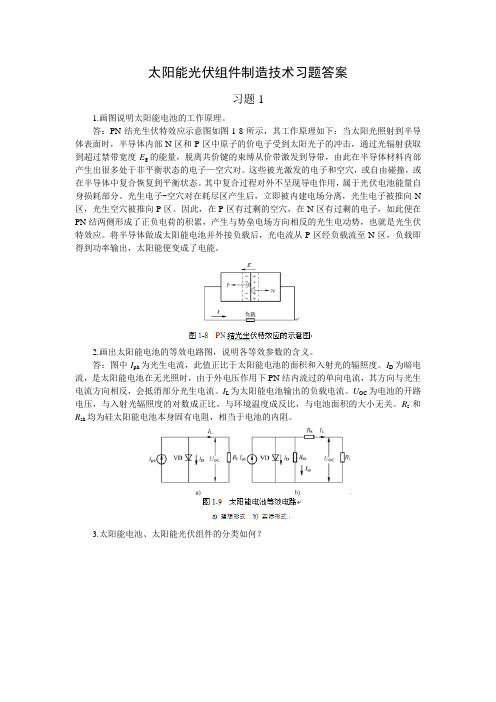
太阳能光伏组件制造技术习题答案习题11.画图说明太阳能电池的工作原理。
答:PN结光生伏特效应示意图如图1-8所示,其工作原理如下:当太阳光照射到半导体表面时,半导体内部N区和P区中原子的价电子受到太阳光子的冲击,通过光辐射获取到超过禁带宽度E g的能量,脱离共价键的束缚从价带激发到导带,由此在半导体材料内部产生出很多处于非平衡状态的电子—空穴对。
这些被光激发的电子和空穴,或自由碰撞,或在半导体中复合恢复到平衡状态。
其中复合过程对外不呈现导电作用,属于光伏电池能量自身损耗部分。
光生电子-空穴对在耗尽区产生后,立即被内建电场分离,光生电子被推向N 区,光生空穴被推向P区。
因此,在P区有过剩的空穴,在N区有过剩的电子,如此便在PN结两侧形成了正负电荷的积累,产生与势垒电场方向相反的光生电动势,也就是光生伏特效应。
将半导体做成太阳能电池并外接负载后,光电流从P区经负载流至N区,负载即得到功率输出,太阳能便变成了电能。
2.画出太阳能电池的等效电路图,说明各等效参数的含义。
答:图中I ph为光生电流,此值正比于太阳能电池的面积和入射光的辐照度。
I D为暗电流,是太阳能电池在无光照时,由于外电压作用下PN结内流过的单向电流,其方向与光生电流方向相反,会抵消部分光生电流。
I L为太阳能电池输出的负载电流。
U OC为电池的开路电压,与入射光辐照度的对数成正比,与环境温度成反比,与电池面积的大小无关。
R s和R sh均为硅太阳能电池本身固有电阻,相当于电池的内阻。
3.太阳能电池、太阳能光伏组件的分类如何?答:太能能光伏组件有以下几种不同的分类。
(1)按照基体材料分类可分为晶硅太阳能光伏组件(单、多晶硅)、非晶硅薄膜太阳能光伏组件、微晶硅薄膜太阳能光伏组件、纳晶硅薄膜太阳能光伏组件、多元化合物太阳能光伏组件(包括砷化镓、硫化镉电池、碲化镉电池、铜硒铟等)。
(2)按照结构分类可分为同质结太阳能光伏组件(在相同的半导体材料上构成PN结)、异质结太阳能光伏组件(在不相同的半导体材料上构成PN结)、肖特基结太阳能光伏组件、复合结太阳能光伏组件、液结太阳能光伏组件等。