RA8835调试笔记
AEMC Instruments Power Quality Analyzer 8345快速入门指南

POWER QUALITY ANALYZERPowerPad ® IVModel 8345ENGLISHQuick Start GuideChauvin Arnoux ®, Inc.d.b.a AEMC ® Instruments Statement of ComplianceChauvin Arnoux ®, Inc. d.b.a. AEMC ® Instrumentscertifies that this instrument has been calibratedusing standards and instruments traceable tointernational standards.We guarantee that at the time of shipping yourinstrument has met the instrument’s publishedspecifications.An NIST traceable certificate may be requested at the time of purchase, or obtained by returning the instrument to our repair and calibration facility, for a nominal charge.The recommended calibration interval for thisinstrument is 12 months and begins on the date ofreceipt by the customer. For recalibration, pleaseuse our calibration services. Refer to our repair andcalibration section at /calibration .Serial #:Cata log #:2136.35 / 2136.36 / 2136.37Model #: 8345Please fill in the appropriate date as indicated:Date Received: Date Calibration Due:(5) 10 ft (3 m) Black Leads with Alligator ClipsCat. #2140.43(1) 5 ft USB CableCat. #2140.46(1) 5.8 A·h 61.9 W·h Li-ion Battery PackCat. #2960.47(1) 1000 V PA32ER Power Supply (Includes Power Plug Adapter)Cat. #5100.15PowerPad ® IV Model 8345(12) Color-coded ID MarkersCat. #2140.45Also included:(1) Quick Start Guide(1) SD Card(1) Carrying Bag Cat. #2133.76(4) MiniFlex® Sensor Model MA194-24-BKCat. #2140.80PowerPad ® IV Model 8345(12) Color-coded ID MarkersCat. #2140.45Also included:(1) Quick Start Guide(1) SD Card(1) Carrying BagCat. #2133.76(5) 10 ft (3 m) Black Leads with Alligator ClipsCat. #2140.43(1) 5.8 A·h 61.9 W·h Li-ion Battery PackCat. #2960.47(1) 5 ft USB CableCat. #2140.46(1) 1000 V PA32ER Power Supply (Includes Power Plug Adapter) Cat. #5100.15(4) AmpFlex® Sensor Model 193-24-BKCat. #2140.34PowerPad ® IV Model 8345(12) Color-coded ID Markers Cat. #2140.45Also included:(1) Quick Start Guide(1) SD Card(1) Carrying BagCat. #2133.76(5) 10 ft (3 m) Black Leads with Alligator ClipsCat. #2140.43(1) 5.8 A·h 61.9 W·h Li-ion Battery PackCat. #2960.47(1) 5 ft USB CableCat. #2140.46(1) 1000 V PA32ER Power Supply (Includes Power Plug Adapter)Cat. #5100.15Thank you for purchasing an AEMC® Instruments PowerPad® IV Model 8345. For best results from your instrument and for your safety, read the enclosed oper-ating instructions carefully and comply with the precautions for use. Only qualified and trained operators should use this product.Symbols & DefinitionsDefinition of Measurement Categories (CAT)CAT IV corresponds to measurements at the source of low-voltage installations. Example: power feeders, counters, and protection devicesCAT III corresponds to measurements on building installations.Example: distribution panel, circuit-breakers, machines, and fixed industrial devices CAT II corresponds to measurements on circuits directly connected tolow-voltage installations.Example: power supply to domestic electrical devices and portable toolsRemoving The Battery Pack1. Disconnect anything connected to the instrument.2. Turn the instrument over and insert a flat-head screwdriver into the batteryrelease recess.3. Push down on the screwdriver to release the battery.4. Use the notches to extract the battery from its compartment.5. Remove the plastic film between the battery and instrument. The plastic filmis used for shipping only.6. Press the battery down until you hear the click of the locking mechanism.Do not treat old batteries as household waste. Take them to the appro-priate collection point for recycling.Without a battery, the instrument’s internal clock will continue to operate for at least 17 hours.Charging the BatteryFollowing shipping safety protocols this unit's battery is charged to only 30 %. Before using the instrument, you must fully charge the battery.1. Connect the power cord to the power supply unit using the supplied adapter.2. Plug the power cord into an outlet.3. Open the elastomer cover that protects the power socket.4. C onnect the power supply’s 4-point connector to the instrument.The ON/OFF button will blink while charging, and the display will indicate the charging status.When the battery is fully depleted, the charging time is approximately 6 hours. The ON/OFF button will glow steady green when the battery is fully charged. DescriptionMeasurement Terminals4 current input terminalsOverall ViewMeasurement terminalsTouch screenConfiguration buttonHelp buttonUSB portSD card slot Mode buttons(Violet buttons)Confirm buttonNavigation buttonsReturn buttonScreenshot buttonON/OFF buttonSide ConnectorsTheft-proofing device for securing the instrument with aKensington lock.RJ45 connector for Ethernet connectionUSB type B connector for connection to a PCSpecial 4-point connector for the power supply. Used to chargethe battery or operate the instrument on external powerInstalling the Color CodesDistribution Systems and Types of ConnectionsConnections on a single-phase netw orkConnections on a split-phase ne tworkConnections on a three-phase netw orkFor three-phase, 3-wire networks, you must indicate the connected current sensors: all 3 sensors (3A) or only 2 (A1 and A2, or A2 and A3, or A3 and A1).For three-phase, 4- and 5-wire networks, you must indicate the connected voltages: all 3 voltages (3V) or only 2 (V1 and V2, or V2 and V3, or V3 and V1).Single-phase2 wires(L1 and N)Single-phase 3 wires (L1, N, and earth)Split-phase2 wires(L1 and L2)Split-phase 3 wires (L1, L2, and N)Split-phase 4 wires(L1, L2, N, and earth)Three-phase3 wires(L1, L2, and L3)Three-phase 5 wires (L1, L2, L3, N, and earth)Three-phase 4 wires(L1, L2, L3, and N)Instrument Configuration ButtonsMeasurement Configuration ButtonsTaking Screenshots■and then black■Press the symbol in the status bar at the top of the display. The symbol in the status bar will turn yellow and then blackDisplayReal-Time Modes Waveform Mode■Press the button to enter Waveform modeThe Waveform mode displays voltage curves, current curves, and values calcu-lated from the voltage and currents, except harmonics, powers, and energies.■button to enter Harmonics mode The Harmonics mode displays a bargraph that represents the harmonics ofthe voltage, current, and mains signaling voltage (MSV).ScreenshotModeHelpReturn to main screen Available functions(mode-dependent)Date and time Frequency measured Connection: USB driveUSB linkEthernet linkBattery charge level Display for the chosenmode and functionDisplay filter■The Power mode displays power measurements (W) and power factor calculations (PF).■ button to enter Energy modeThe Energy mode is used to meter generated and consumed energy over a period and indicate the corresponding price.Recording Modes■ button and select a recording from the list to view the associated Trend measurements.The Trend mode records the evolution of the quantities selected in the configura-tion for a specified duration.associated Transient measurements.The Transient mode records voltage or current transients for a specified duration determined by the selected configuration. It also records shock waves, which are very high voltages for a very short time.Inrush Current Mode■Press the button and select a recording from the list to view the associated Inrush Current measurements.The Inrush Current mode is used to capture and record inrush currents for a duration specified by the selected configuration.■ button and select a recording from the list to view the associated Alarm measurements.The Alarm mode detects and records overshoots of the selected quantities in configuration for a specified duration.The Monitoring mode is used to check the voltage’s conformity for a specified duration. Use the application software to configure the Monitoring mode.The Monitoring mode monitors electrical networks per standard EN 50160. In this mode, the 8345 detects slow variations, rapid variations and interruptions, voltage dips, temporary voltage swells, and transients. The monitoring mode is configured using the application software as shown in the below image.■corded screenshotsThe screenshots are recorded on the SD card in the directory 8345\Photograph. You can read the screenshots on a PC via the application software or an SD card reader (not provided).■ button for information about the in-progress display mode's various button functions and symbolsApplication SoftwareThe application software is available on the provided USB drive or on our website at /dataview-software .Go to the Support tab and search for the application software by name, then download it.Remove the cover that protects the USB connector on the instrument andconnect the instrument to the PC using the provided USB cord.NOTE: USB 3.1 Gen 2 Super Speed is not supported on some PCs using Windows 10 operating system. In this situation, we recommend switching to either a lower speed USB port or ethernet connection .Start the application software.SSUSB 3.1 Gen 2Repair and CalibrationTo ensure that your instrument meets factory specifications, we recommend that it be sent back to our factory Service Center at one-year intervals for recalibration or as required by other standards or internal procedures.For instrument repair and calibration:You must contact our Service Center for a Customer Service Authorization Number (CSA#). Send an email to *************** requesting a CSA#,you will be provided a CSA Form and other required paperwork along with the next steps to complete the request. Then return the instrument along with the signed CSA Form. This will ensure that when your instrument arrives, it will be tracked and processed promptly. Please write the CSA# on the outside of the shipping container. If the instrument is returned for calibration, we need to know if you want a standard calibration or a calibration traceable to N.I.S.T. (includes calibration certificate plus recorded calibration data).Ship To: Chauvin Arnoux®, Inc. d.b.a. AEMC® Instruments15 Faraday Drive ▪ Dover, NH 03820 USAPhone: (800) 945-2362 (Ext. 360) / (603) 749-6434 (Ext. 360)Fax: (603) 742-2346E-mail: ***************(Or contact your authorized distributor.)Contact us for the costs for repair, standard calibration, and calibration traceable to N.I.S.T.NOTE: You must obtain a CSA# before returning any instrument.Technical AssistanceI If you are experiencing any technical problems or require any assistance with the proper operation or application of your instrument, please call, e-mail or fax our technical support team:Chauvin Arnoux®, Inc. d.b.a. AEMC® InstrumentsPhone: (800) 343-1391 (Ext. 351)Fax: (603) 742-2346E-mail: ********************Limited WarrantyThe instrument is warrantied to the owner for a period of two years from the date of original purchase against defects in manufacture. This limited warranty is given by AEMC® Instruments, not by the distributor from whom it was purchased. This warranty is void if the unit has been tampered with, abused, or if the defect is related to service not performed by AEMC® Instruments.Full warranty coverage and product registration is available on our website at /warranty.htmlPlease print the online Warranty Coverage Information for your records. What AEMC® Instruments will do:If a malfunction occurs within the warranty period, you may return the instrument to us for repair, provided we have your warranty registration information on file or a proof of purchase. AEMC® Instruments will repair or replace the faulty material at our discretion.REGISTER ONLINE AT: /warranty.htmlWarranty RepairsWhat you must do to return an Instrument for Warranty Repair:First, send an email to *************** requesting a Customer Service Authorization Number (CSA#) from our Service Department. You will be provided a CSA Form and other required paperwork along with the next steps to complete the request. Then return the instrument along with the signed CSA Form. Please write the CSA# on the outside of the shipping container. Return the instrument, postage or shipment pre-paid to:Chauvin Arnoux®, Inc. d.b.a. AEMC® Instruments15 Faraday Drive, Dover, NH 03820 USAPhone: (800) 945-2362 (Ext. 360)(603) 749-6434 (Ext. 360)Fax: (603) 742-2346E-mail: ***************Caution: To protect yourself against in-transit loss, we recommend that you insure your returned material.NOTE: You must obtain a CSA# before returning any instrument.Quick Start Guide TranslationsVisit our website to view and download a PDF version of this Quick Start Guide: Español FrançaisNOTES:AEMC ® Instruments15 Faraday Drive • Dover, NH 03820 USAPhone: (603) 749-6434 • (800) 343-1391 • Fax: (603) 742-234606/2399-MAN 100564 v03。
RA8835调试笔记
Bit0 1
Bit0 MX0
Bit0 0
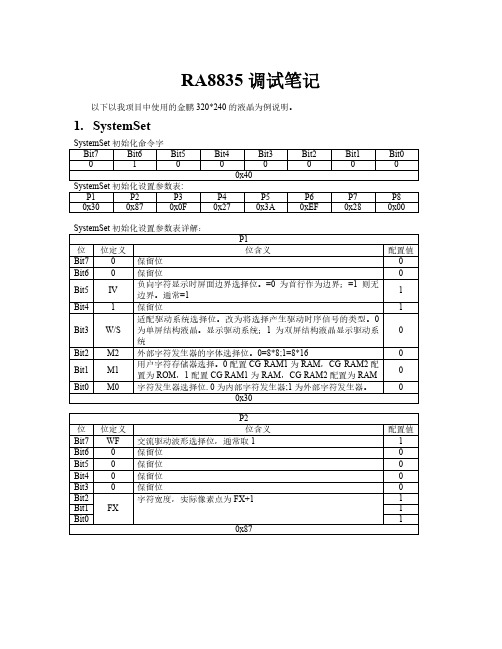
HDOT SCR 设置参数 P1
Bit7
Bit6
Bit5
Bit4
Bit3
Bit2
Bit1
Bit0
0
0
0
0
0
D2
D1
D0
配置没有水平滚动效果 0x00
6. CSRFORM光标模式选择
CSRFORM 命令字
Bit7
Bit6
Bit5
Bit4
Bit3
Bit2
Bit1
DM1、DM0 设置 DM1 0 设置显示区一位字符模式,1 设置显示区一为图形模式 DM2 0 设置显示区三位字符模式,1 设置显示区三为图形模式
备注:显示区二、四为图形模式。
5. HDOT SCR
HDOT SCR 命令字
Bit7
Bit6
Bit5
Bit4
Bit3
Bit2
Bit1
0
1
0
1
1
0
1
0x5A
Bit5
TC/R >= C/R +4,我这里采用的是液晶供应商推荐值
1
Bit4 Bit3
TC/R
1 1
Bit2
0
Bit1
1
Bit0
0
0x3A
P6
位 位定义
位含义
配置值
Bit7
液晶像素点值,如 320*240 的液晶,一列为 240-1=239,减一是 1
Bit6
参数中会自动加一
1
Bit5
1
Bit4 Bit3
P6 0xEF
Bit1 0
P7 0x28
RA8835_Simple_DS_v12_Eng
RA i ORA8835Dot MatrixLCD ControllerSpecificationVersion 1.2June 1, 2005RA i O Technology Inc.©Copyright RAiO Technology Inc. 2004, 20051. OverviewThe RA8835 is a controller IC that can display text and graphics on LCD panel. It can display layered text and graphics, scroll the display in any direction and partition the display into multiple screens. It also stores text, character codes and bitmapped graphics data in external frame buffer memory. Display controller functions include transferring data from the controlling microprocessor to the buffer memory, reading memory data, converting data to display pixels and generating timing signals for the buffer memory, LCD panel.The RA8835 has an internal character generator with 160, 5 X 7 pixel characters in internal mask ROM. The character generators support up to 64, 8 X 16 pixel characters in external character generator RAM and up to 256, 8 X 16 pixel characters in external character generator ROM.2. FeaturesText, graphics and combined text/graphics display modesThree overlapping screens in graphics mode Up to 640 X 256 pixel LCD panel display resolutionProgrammable cursor controlSmooth horizontal and vertical scrolling of all or part of the display1/2-duty to 1/256-duty LCD driveUp to 640 X 256 pixel LCD panel display resolution memory160, 5 X 7 pixel characters in internal mask-programmed character generator ROMUp to 64, 8 X 16 pixel characters in external character generator RAMUp to 256, 8 X 16 pixel characters in external character generator ROM6800 and 8080 family microprocessor interfaces Low power consumption—3.5 mA operating current (V DD = 3.5V), 0.05 μA standby currentPackage:RA8835P3N: QFP-60 pin (Lead Free)RA8835P4N: TQFP-60 pin (Lead Free)Power: 2.7 to 5.5 V3. Block Diagram4. PackageFigure 4-1: RA8835P3N(QFP-60 Pin)V V D 4V D 5V D 6V D 7Y S C L Y D Y D I S W FL P G N D X S C L S E C L X D 0X D 1X D 2A 5V A 4V A 3V A 2V A 1V A 0V W R N C N C R D S E L 2VD3VD2VD1VD0VA15VA14VA13VA12VA11VA10VA9VA8VA7VA6NCXD3D7D6D5D4D3D2D1D0VDD A0XD XG SEL1Figure 4-2: RA8835P4N (TQFP-60 Pin)5. Pin Descriptions5.1.1. MCU Interface5.1.2 Display Memory ControlThe RA8835 series can directly access static RAM and PROM. The designer may use a mixture of these two types of memory to achieve an optimum trade-off between low cost and low power consumption.5.1.3 LCD Drive SignalsIn order to provide effective low-power drive for LCD matrixes, the RA8835 series can directly control both the X- and Y-drivers using an enable chain.Pin Name FunctionXD0 to XD3 Data Output for Driver.4-bit X-driver (column drive) data outputs. Connect these outputs to the inputs of the X-driver chips.XSCL Latch Clock.The falling edge of XSCL latches the data on XD0 to XD3 into the input shift registers of the X-drivers. To conserve power, this clock halts between LP and the start of the following display line (See section 6.3.7).XECL Trigger Clock for Chain Cascade.The falling edge of XECL triggers the enable chain cascade for the X-drivers. Every 16th clock pulse is output to the next X-driver.LP Latch Pulse.LP latches the signal in the X-driver shift registers into the output data latches. LP is a falling-edge triggered signal, and pulses once every display line. Connect LP to the Y-driver shift clock on modules.WF AC Drive Output.The WF period is selected to be one of two values with SYSTEM SET command.YSCL Latch Clock for YD.The falling edge of YSCL latches the data on YD into the input shift registers of the Y-drivers. YSCL is not used with driver ICs which use LP as the Y-driver shift clock.YD Data Pulse Output for Y Drivers.It is active during the last line of each frame, and is shifted through the Y drivers one by one (by YSCL), to scan the display’s common connections.YDIS Power-down Output Signal.YDIS is HIGH while the display drive outputs are active. YDIS goes LOW one or two frames after the sleep command is written to the RA8835 series. All Y-driver outputs are forced to an intermediate level (de-selecting the display segments) to blank the display. In order to implement power-down operation in the LCD unit, the LCD power drive supplies must also be disabled when the display is disabled by YDIS.5.1.4. Oscillator and PowerPin Name FunctionXG Crystal Connection for Internal OscillatorThis pin can be driven by an external clock source that satisfies the timing specifications of the EXT f0 signal (See section 7.3.6).XD Crystal Connection for Internal OscillatorLeave this pin open when using an external clock source.VDD 2.7 to 5.5V Supply.This may be the same supply as the controlling microprocessor.GNDGround TESTTest Pin.This is a test pins. No need for connection(NC).Note: The peak supply current drawn by the RA8835 series may be up to ten times the averagesupply current. The power supply impedance must be kept as low as possible by ensuring that supply lines are sufficiently wide and by placing 0.47μF decoupling capacitors that have good high-frequency response near the device’s supply pins.6. System Application。
第3章RA8875屏触摸校准自适应

第3章RA8875屏触摸校准自适应将本期教程放在第三章主要是方便开发板用户可以直接运行后面章节中的例子,而不用每次执行例子前都做一次触摸的校准,本期教程提供的方法可以将触摸参数保存到EEPROM里面,以后使用只需从EEPROM加载这个参数即可。
本期教程提供的校准方法可以自适应安富莱生产的RA8875 -4.3寸,5寸和7寸屏。
3.1 触摸校准基础知识介绍3.2 触摸屏校准步骤3.3 触摸参数自动加载3.4总结3.1触摸校准基础知识介绍这部分基础的知识大家有个了解即可,不了解也没有关系,通过后面几期简单的学习后,会抽出一章专门的讲解触摸校准方面的知识。
1.STemWin自带的触摸校准函数在X轴镜像,Y轴镜像或者都镜像的情况下依然可以正常使用。
认识到这点非常的关键,要不搞着搞着就把自己绕进去了。
2.大家拿到LCD屏以后,要显示图片、文字等的时候,不外乎横屏或者竖屏显示,一旦显示方式确定了,那么屏的扫描方式也就确定了(啥是扫描方式,也是就是X,Y轴坐标地址的递增方向)。
扫描方式确定下来以后,后面所有的操作都要以这个为参照对象,咱们前面说的X轴镜像,Y轴镜像就是以这个为参照对象的。
3.STemWin自带的触摸函数是校准不了X,Y轴翻转的,这个大家一定要认识到,咱们主要解决的也就是X,Y翻转。
4.STemWin底层在获取X,Y轴ADC数值的时候,只要保证:int GUI_TOUCH_X_MeasureX(void) //这里用于获取X轴ADC的数值int GUI_TOUCH_X_MeasureY(void) //这里用于获取Y轴ADC的数值底层保证读取位置一致,需要做修改的话都放在应用层。
5.学习一下官方的GUI_TOUCH_SetOrientation函数。
6.校准好参数以后将结果保存到EEPROM里面,以后开机直接加载即可。
3.2触摸屏校准步骤3.2.1第一步:下载触摸自适应校准程序到开发板这个工程代码是裸机的STemWin5.22,工程文件如下:3.2.2第二步:进行触摸校准将程序下载到板子里面之后,显示效果如下:先点击左上角的小圆圈(最好找个触摸笔点击,这样比较准确),点击后效果如下:然后在点击右下角的小圆圈,点击后效果如下:进入到这步以后表示触摸校准已经成功,并且触摸参数已经保存到了EEPROM里面,用户可以在这个界面上实现简单的绘图功能,观察触摸是否准确,如果不准确请重新启动板子,再次进行校准。
Adafruit AMG8833 8x8热成像传感器说明书

Adafruit AMG8833 8x8 Thermal Camera SensorCreated by Dean MillerLast updated on 2018-08-22 04:01:13 PM UTC23666889101212121314151617171919191920202122232324242424242629292929Guide ContentsGuide Contents Overview PinoutsPower Pins:Logic pins:AssemblyPrepare the header strips:Add the breakout board:And Solder!Arduino Wiring & Test I2C WiringDownload Adafruit_AMG88xx library Load Thermistor Test Pixel Array Output Library Reference Arduino Library Docs Arduino Thermal CameraAdafruit 1.44" Color TFT LCD Display with MicroSD Card breakoutPython & CircuitPythonCircuitPython Microcontroller Wiring Python Computer WiringCircuitPython Installation of AMG88xx Library Python Installation of AMG88xx Library CircuitPython & Python Usage Full Example Code Python DocsRaspberry Pi Thermal CameraRaspberry Pi 3 - Model B - ARMv8 with 1G RAMPiTFT Plus Assembled 320x240 2.8" TFT + Resistive Touchscreen Assembled Pi T-Cobbler Plus - GPIO BreakoutSetup PiTFTInstall Python Software Wiring Up Sensor Run example code Downloads Documents Schematic DimensionsOverviewAdd heat-vision to your project and with an Adafruit AMG8833 Grid-EYE Breakout! This sensor from Panasonic is an 8x8 array of IR thermal sensors. When connected to your microcontroller (or raspberry Pi) it will return an array of 64 individual infrared temperature readings over I2C. It's like those fancy thermal cameras, but compact and simple enough for easy integration.This part will measure temperatures ranging from 0°C to 80°C (32°F to 176°F) with an accuracy of +- 2.5°C (4.5°F). It can detect a human from a distance of up to 7 meters (23) feet. With a maximum frame rate of 10Hz, It's perfect for creating your own human detector or mini thermal camera. We have code for using this breakout on an Arduino or compatible (the sensor communicates over I2C) or on a Raspberry Pi with Python. On the Pi, with a bit of image processing help from the SciPy python library we were able to interpolate the 8x8 grid and get some pretty nice results!The AMG8833 is the next generation of 8x8 thermal IR sensors from Panasonic, and offers higher performance than it's predecessor the AMG8831. The sensor only supports I2C, and has a configurable interrupt pin that can fire when any individual pixel goes above or below a thresholds that you set.To make it easy to use, we pick & placed it on a breakout board with a 3.3V regulator and level shifting. So you can use it with any 3V or 5V microcontroller or computer.Even better - We've done all the hard work here, with example code and supporting software libraries to get you up inrunning in just a few lines of code!PinoutsThis camera has 4 mounting holes, and two header strips. Only the bottom strip is connected to the sensor. The top set of breakouts is there for mechanical stability only!The 6 holes at the top of the board are provided for stability and are not connected to anything. Use these if you wantyour sensor to sit nice and flat on a breadboard or Perma-Proto.AssemblyPrepare the header strips:Cut the strips to length if necessary. It will be easier tosolder if you insert it into a breadboard - long pins downAdd the breakout board:Place the breakout board over the pins so that the shortpins poke through the breakout padsAnd Solder!Be sure to solder all pins for reliable electrical contact. (For tips on soldering, be sure to check out our Guide to Excellent Soldering (https://adafru.it/aTk)).You're done! Check your solder joints visually and Arraycontinue onto the next stepsYou can easily wire this breakout to any microcontroller, we'll be using an Arduino. You can use any other kind of Download Adafruit_AMG88xx libraryTo begin reading sensor data, you will need to install the Adafruit_AMG88xx library (https://adafru.it/xfw).Start up the IDE and open the Library Manager:Type in AMG88xx until you see the Adafruit Library pop up. Click Install!We also have a great tutorial on Arduino library installation at:/adafruit-all-about-arduino-libraries-install-use (https://adafru.it/aYM)Load Thermistor TestOpen up File->Examples->Adafruit_AMG88xx->amg88xx_test and upload to your Arduino wired up to the sensor. This example just connects to the sensor and reads the internal thermistor to test your connections.Once uploaded to your Arduino, open up the serial console at 9600 baud speed to see the internal thermistor reading. If you get a reading of ~26° degrees (room temperature) then everything is wired and working correctly!Pixel Array OutputOK now that we know the sensor is working, let's read actual thermal data. Load up File -> Examples ->Adafruit_AMG88 -> pixels_testUpload the code, and open the serial console at 9600 baud rate. You should see a printout of the array of readings every second. Each number is the detected temperature in Celsius, and in the 8x8 grid order that comes from the sensorThe numbers should increase if you put your hand or face above the sensor. They'll decrease if you hold up something cold in front of the sensor eyeLibrary ReferenceTo create the object, useInitialize the sensor usingto read the pixels you will need an array to place the readings into. Once you have one, you can call readPixels. Make sure the array you create is big enough by using the pre-defined AMG88xx_PIXEL_ARRAY_SIZE macro.Adafruit_AMG88xx amg;status = amg.begin();if (!status) {Serial.println("Could not find a valid AMG88xx sensor, check wiring!");while (1);}float pixels[AMG88xx_PIXEL_ARRAY_SIZE];amg.readPixels(pixels);Arduino Library DocsArduino Library Docs (https://adafru.it/Au6)Arduino Thermal CameraTo make your Arduino into a cool thermal camera, we can add a small display.In this example we use an Adafruit 1.44" Color TFT. With some code changes, you can use other size displays but a color display is best of course.Keep your AMG8833 breakout wired as you already have it from the Wiring & Test section above, and add your TFT like thisOnce everything is all wired up, load up File->Examples->Adafruit_AMG88xx->thermal_camHit upload and you should have a simple thermal camera!Adafruit 1.44" Color TFT LCD Display with MicroSD Card breakout$14.95IN STOCKADD TO CARTJames DV has also sent over a version that is optimized if you want a faster display-update rate(https://adafru.it/BPj)Adafruit CircuitPythonPython Computer WiringSince there's dozens of Linux computers/boards you can use we will show wiring for Raspberry Pi. For other platforms, please visit the guide for CircuitPython on Linux to see whether your platform is supportedCircuitPython Installation of AMG88xx LibraryYou'll need to install the Adafruit CircuitPython AMG88xxFirst make sure you are running theThat's all there is to using AMG88ss with CircuitPython! Full Example Codeimport timeimport busioimport boardimport adafruit_amg88xxi2c = busio.I2C(board.SCL, board.SDA)amg = adafruit_amg88xx.AMG88XX(i2c)while True:for row in amg.pixels:# Pad to 1 decimal placeprint(['{0:.1f}'.format(temp) for temp in row]) print("")print("\n")time.sleep(1)Python DocsPython Docs (https://adafru.it/C41)Raspberry Pi Thermal CameraThe Raspberry Pi also has an i2c interface, and even better has processing capability to interpolate and filter the sensor output. By adding processing power, you can 'turn' the 8x8 output into what appears to be a higher-resolution display.We're using a PiTFT 2.8" and a Pi Cobbler but the code can be adapted to output to the HDMI display - we're using pygame to draw to the framebuffer.You can use any Raspberry Pi computer, from Pi A+ to Pi 3 or even a Pi Zero, but we happen to have a Pi 3 on our desk set up already so we're using that.Raspberry Pi 3 - Model B - ARMv8 with 1G RAM$35.00IN STOCKADD TO CARTSetup PiTFTIf you have not done so already, the first thing you will need to do is setup your PiTFT. Instructions on how to do so can be found in this guide (https://adafru.it/sha).Install Python SoftwareOnce your PiTFT is all set up, and you have Internet access set upfor the AMG8833 so you can read data from the sensor.Finally, install both pygame and scipy. Pygame lets us draw easily to a screen using python, we'll use that to make the display work. Scipy is a powerful scientific/data processing library that we can use to magically turn the 8x8 = 64 pixel array into something that looks more like a 32x32 = 1024 pixel array. Wow, isn't digital signal processing cool?You can also use direct wires, we happen to have a Cobbler ready. remember you can plug the cobbler into the bottom of the PiTFT to get access to all the pins!Now you should be able to verify that the sensor is wired up correctly by asking the Pi to detect what addresses it can see on the I2C bus:It should show up under it's default address (0x69). If you don't see 0x69, check your wiring, did you install I2Csudo i2cdetect -y 1support, etc?Run example codeAt long last, we are finally ready to run our example code"""This example is for Raspberry Pi (Linux) only!It will not work on microcontrollers running CircuitPython!"""import osimport mathimport timeimport busioimport boardimport numpy as npimport pygamefrom scipy.interpolate import griddatafrom colour import Colorimport adafruit_amg88xxi2c_bus = busio.I2C(board.SCL, board.SDA)#low range of the sensor (this will be blue on the screen)MINTEMP = 26.#high range of the sensor (this will be red on the screen)MAXTEMP = 32.#how many color values we can haveCOLORDEPTH = 1024os.putenv('SDL_FBDEV', '/dev/fb1')pygame.init()#initialize the sensorsensor = adafruit_amg88xx.AMG88XX(i2c_bus)# pylint: disable=invalid-slice-indexpoints = [(math.floor(ix / 8), (ix % 8)) for ix in range(0, 64)]grid_x, grid_y = np.mgrid[0:7:32j, 0:7:32j]# pylint: enable=invalid-slice-index#sensor is an 8x8 grid so lets do a squareheight = 240width = 240#the list of colors we can choose fromblue = Color("indigo")colors = list(blue.range_to(Color("red"), COLORDEPTH))#create the array of colorscolors = [(int(c.red * 255), int(c.green * 255), int(c.blue * 255)) for c in colors]displayPixelWidth = width / 30displayPixelHeight = height / 30If you have everything installed and wired up correctly, you should see a nice thermal camera image. Cool tones (blue and purple) are cooler temperatures, and warmer tones (yellow, red) are warmer temperatures.If your image seems to be flipped on the screen, try changing the orientation of the AMG8833 breakout on the breadboard.If you're interested int he details, and want to know more about how we made 64 pixels look like many more, it's called bicubic interpolation (https://adafru.it/xgA) (hat tip to OSHpark for the idea (https://adafru.it/xgB)!)displayPixelHeight = height / 30lcd = pygame.display.set_mode((width, height))lcd.fill((255, 0, 0))pygame.display.update()pygame.mouse.set_visible(False)lcd.fill((0, 0, 0))pygame.display.update()#some utility functionsdef constrain(val, min_val, max_val):return min(max_val, max(min_val, val))def map_value(x, in_min, in_max, out_min, out_max):return (x - in_min) * (out_max - out_min) / (in_max - in_min) + out_min#let the sensor initializetime.sleep(.1)while True:#read the pixelspixels = []for row in sensor.pixels:pixels = pixels + rowpixels = [map_value(p, MINTEMP, MAXTEMP, 0, COLORDEPTH - 1) for p in pixels]#perform interpolationbicubic = griddata(points, pixels, (grid_x, grid_y), method='cubic')#draw everythingfor ix, row in enumerate(bicubic):for jx, pixel in enumerate(row):pygame.draw.rect(lcd, colors[constrain(int(pixel), 0, COLORDEPTH- 1)],(displayPixelHeight * ix, displayPixelWidth * jx,displayPixelHeight, displayPixelWidth))pygame.display.update()Dimensions。
RA8835显示程序

//
ET0=1;
ES0=1;
ห้องสมุดไป่ตู้
}
/*-----------------------------------------------------------------------
DISPLAY _OFF()显 示屏关闭
-----------------------------------------------------------------------*/ void DISPLAY _OFF() {
SYSTEM SET_RA 8835()L CM系统 设置 -----------------------------------------------------------------------*/ void SYSTEM SET_RA 8835() {
ET0=0;
ES0=0;
//
wrcomm and_RA8 835(0x4 0); // 命令40H 参数设 置, #0101H 为命令口 地址
SFRPAG E=15;
//
RST_RA 8835=0;
delay_m s(500);
RST_RA 8835=1;
//
SFRPAG E=0;
SFRPAG E=SFRP AGE_RA M;
delay_m s(200);
EA=1; }
/*-----------------------------------------------------------------------
//片选
SFRPAG E_RAM= SFRPAG E;
SFRPAG E=15;
CS_RA8 835=0;
SED1335&RA8835

;=================================LCD SCROLL命令========================
MOV DPTR,#COM
MOV A,#44H
SD3L EQU 00H ;第三区开始显示的显缓首地址的低八位
SD3H EQU 4BH ;第三区开始显示的显缓首地址的高八位
ORG 0000H
AJMP MAIN
MOV CSRH,#SD2H
MOV DPTR,#GONG1
MOV R7,#30
LCALL ADDR7
LCALL WHZ64
MOV CSRL,#4AH
MOV CSRH,#38H
MOV DPTR,#HE1
LCALL WHZ32
MOV CSRL,#4AH
MOV CSRH,#38H
MOV CSRH,#SD2H
MOV DPTR,#DU1
MOV R7,#10
LCALL ADDR7
LCALL WHZ64
MOV CSRL,#SD2L
MOV CSRH,#SD2H
MOV DPTR,#LI1
MOV R7,#20
LCALL ADDR7
LCALL WHZ64
MOV CSRL,#SD2L
MOV DPTR,#GONG2
MOV R7,#4
LCALL ADDR7
LCALL WHZ32
MOV CSRL,#4AH
MOV CSRH,#38H
MOV DPTR,#CHENG2
MOV R7,#8
LCALL ADDR7
LCALL WHZ32
3M883三相高性价比细分步进驱动器使用手册说明书
3M883(三相高性价比)细分步进驱动器使用手册Version1.0版权所有不得翻印【使用前请仔细阅读本手册,以免损坏驱动器】宁波纳川自动化科技有限公司3M883步进电机驱动器使用说明在使用本品前,请仔细阅读本使用说明书请妥善保管本说明书,以备日后参考本册外观图片仅供参考,请以实物为准安全注意事项请勿带电插拔连接线缆。
此产品非密封,请勿在内部混入镙丝、金属屑等导电性异物或可燃性异物,储存和使用时请注意防潮防湿。
驱动器为功率设备,尽量保持工作环境的散热通风。
在连上步进电机,调节好电流后使其连续工作半小时后观察步进电机是否在额定温度后方可进行后续使用,如果电机温度过高请联系制造商。
一、产品简介1.1 产品概述3M883是纳川科技最新推出的一款采用精密电流控制技术设计的高细分步进电机驱动器,适合驱动57-86型各种品牌的三相混合式步进电机。
由于采用了先进的抗噪声控制方法,能大幅度降低电机运转时的噪声和振动,使得步进电机运转时的噪声和平稳性趋近于伺服电机的水平。
和市场上的大多数其他细分驱动产品相比,步进电机和驱动器的发热量降幅达15-30%。
1.2 产品特点●高性能、低价格、超低噪声●电机和驱动器发热很低●供电电压可达 80VDC●输出电流峰值可达 8.3A(均值 5.9A)●输入信号 TTL 兼容●静止时电流自动减半●可驱动 3,6 线三相步进电机●光隔离差分信号输入●脉冲响应频率最高可达 400KHz(更高可选)●多达 16 种细分可选●具有过压、欠压、短路等保护功能●脉冲/方向或 CW/CCW 双脉冲功能可选1.3 应用领域适合各种大型自动化设备和仪器,例如:雕刻机、打标机、切割机、激光照排、绘图仪、数控机床、拿放装置等。
在用户期望低成本、小噪声、高速度的设备中效果特佳。
二、电气、机械和环境指标2.1 电气指标说明3M883最小值典型值最大值单位输出电流 2.1 - 8.3(均值5.8) A 输入电源电压18 68 80(含纹波)VDC 逻辑输入电流7 10 16 mA 步进脉冲频率0 - 400 KHZ脉冲低电平时间1.2Us绝缘电阻500 MΩ2.2 使用环境及参数冷却方式自然冷却使用环境场合尽量避免粉尘、油雾及腐蚀性气体环境温度0℃-+50℃最高工作温度70℃湿度40-90% RH9 (不能结露和有水珠)震动 5.9m/S2 Max保存温度-20℃-125℃重量约550克2.3 机械安装图 单位:毫米2.4 加强散热方式(1)驱动器的可靠工作温度通常在65℃以内,电机的工作温度在80℃以内;(2)建议使用时选择自动半流方式,即马达停止时电流自动减一半,以减少电机和驱动器的发热;(3)安装驱动器时请采用竖着侧面安装,形成较强的空气对流,必要时机内靠近驱动器出安装风扇,强制散热,保证驱动器在可靠的工作温度范围内工作。
7135 350mA电源LED驱动器应用笔记

7135上海毅钧商贸有限公司Contents1. General Description (1)2. Features (1)3. Ordering Information.......................................................................... (1)4. Component List (2)5. Demo Board User Guide.................................................... .. (2)(1) Demo Board Circuit (2)(2) Application of 7135 (3)(3) Characteristics of LED (3)A. I F / Lumens (3)B. V F / Lumens (4)C. Temperature (5)(4) Characteristics of Battery............................................... .. (7)6. Quick Start (9)(1) Performance measurement (9)A. Directly driven by Battery (9)a. Test Circuit (9)b. Battery Voltage vs. Life time (10)c. LED Driving Current vs. Life time (10)B. Driven by 7135 (11)a. Test Circuit (11)b. Battery Voltage vs. Life time (11)c. LED Driving Current vs. Life time (12)C. Comparison of Different LED Driving Method (12)(2) Trouble Sheeting (13)A. Reverse Battery Protection (13)B. Input Voltage Higher than 6V (14)7. PCB Layout (15)(1) Picture of Demo Board (15)(2) Demo Board Layout (16)8. Reference (18)圖目錄圖一 7135 Demo Board 電路圖 (2)圖二 LumiLED-DS47 / Lux-I F之關係圖 (3)圖三 Edixeon 1W Emitter / Lux-I F之關係圖 (4)圖四 LumiLED-DS47 / I F-V F之關係圖 (4)圖五 Edixeon 1W Emitter / V F-I F之關係圖 (5)圖六 5-mm 白光 LED 及 High Power LED 測試圖[Source : LumiLEDs] (6)圖七 High Power LED 光輸出受溫度之影響[Source : LumiLEDs] (6)圖八 High Power LED 光輸出受電流之影響[Source : LumiLEDs] (7)圖九 Energizer Battery / 電壓-時間(分) @輕載[Source : Energizer] (8)圖十 Energizer Battery / 電壓-時間(分) @重載[Source : Energizer] (8)圖十一 不加穩流 IC 時測試線路圖 (9)圖十二 不加穩流IC時,電池之使用時間與電池電壓之關係 (10)圖十三 不加穩流IC時LED電流隨時間之變化圖 (10)圖十四 加上7135穩流IC時測試線路圖 (11)圖十五 加上穩流IC 7135時,電池之使用時間與電池電壓之關係 (11)圖十六 加上穩流IC 7135時LED電流隨時間之變化圖 (12)圖十七 比較有無穩流 IC 之差別 (12)圖十八 使用1N4148保護迴路電路圖 (13)圖十九 使用 6V 以上 8V 以下之較高電壓輸入時之線路 (14)圖二十 實際 Demo Board (15)圖二十一 Demo Board Layout 圖 (16)表目錄表一 7150EKM評估工具版元件列表 (2)表二 Power LED 規格表 (2)圖一 7135 Demo Board 電路圖圖一之架構中使用觸碰式開關(Touch SW)以及常開/常關控制開關(Slide SW)動作的兩種方式,方式不同但功能相同。
液晶模块G320240A(RA8835)附程序

一:模块命名规则PART NUMBER: HP-AB..BC-D-EFGHIJ-KLHPA DISPLAY CONTENTS C---CHARACTER TYPE(字符型)G---GRAPHIC TYPE (点阵型)B…B SERIALS NUMBER FOR SM CHARACTERS Vs. LINES FOR CM(字符数VS行数)COLUMNS Vs. ROWS FOR GM(列VS行)C VERSION OF PCB(PCB版本号)D DIFFERENT TYPE OF THE SAME PART(修改版本)E LCD TYPE:P---POS. TN, N---NEG. FSTN, Y---YELLOW STN, G---GRAY STNB---BLUE STN, F---FSTN POSITVEF POLARIZER TYPE(偏光片类型)R---REFLECTIVE(反射), F---TRANSFLECTIVE(半透), T---TRANSMISSIVE(全透)G VIEWING ANGLE 6---6 O’CLOCK, 0---12 O’CLOCK,3---3 O’CLOCKH OPERATING TEMPRETURE N---NORMAL, E---EXTENDEDI BACKLIGHT TYPE: N---NO BACKLIGHT, D---BOTTOM LED, S---SIDE LED,J COLOR OF BACKLIGHT Y---YELLOW/GREEN, G---GREENW---WHITE, B---BLUE, A---AMBERKL FOR CM, CONTROLLER/DRIVER DESIGNATORJ: IC TYPEK: DENOTE DIFFERENT CHARACTER TABLEFOR GM. J: BACKLIGHT DRIVER Y---WITH, N---WITHOUTK: DC-DC CONVERTER Y---WITH, N---WITHOUTFOR EXAMPLE: HP-C2001A-1-YF6EDY-B0HPC CHARACTER TYPE(字符型)2001 20 CHARACTER PER LINES 1 ROWS (每行20个字符,共1行)A A VERSION OF PCB(PCB为A版本)1 THE FIRST TYPE (第一次修改)Y LCD TYPE IS YELLOW/GREEN STN(液晶屏的颜色为黄绿色)F POLARIZER TYPE IS TRANSFLECTIVE(液晶的偏光片为半透型)6 VIEWING ANGLE IS 6 O’CLOCK(液晶的视角为6点钟视角)E EXTENDED TEMPRETURE (操作温度为宽温型)D BACKLIGHT TYPE BOTTOM LEDE LED (背光类型为:底背光)Y COLOR OF BACKLIGHT Y---YELLOW/GREEN (背光颜色为黄绿色)B0 B: CONTROL IC TYPE IS SUNPLUS(控制IC为凌阳)K: DENOTE CHARACTER TABLE IS 00(IC的字库为CODE 00)时序说明 at Ta = 25 deg C, Vdd = 5V+/-10%, Vss =0V项目符号最小值最大值单位地址延时时间Tah8 13 - ns 地址上升时间Taw8 5 - ns 系统循环时间Tcyc8 (*2)- ns 存储脉冲建立时间Tcc8 190 - ns 数据保持时间Tdh8 7 - ns 数据建立时间Tds8 190 ns 数据稳态时间Tacc8 13 - ns时序说明at Ta = 25 deg C, Vdd = 3.3V+/-10%, Vss =0V项目符号最小值最大值单位地址延时时间Tah8 13 - ns 地址上升时间Taw8 5 - ns 系统循环时间Tcyc8 (*2)- ns 存储脉冲建立时间Tcc8 150 - ns 数据保持时间Tdh8 7 - ns 数据建立时间Tds8 150 ns 数据稳态时间Tacc8 7 - ns 说明:*1. 输入信号的上升/下降时间不应该小于20 NS*2. 对于存储控制和系统控制指令:tcyc8=2tc+Tcea+75>tacv+245*3. 对于所有其他的指令:tcyc8=4tc+tcc8+30*4. 关于详细的说明请参考RA8835的数据手册(2)6800 时序时序说明 at Ta = 25 deg C, Vdd = 5V+/-10%, Vss =0V项目符号最小值最大值单位地址延时时间Tah6 13 - ns 地址上升时间Taw6 5 - ns 系统循环时间Tcyc6 (*2)- ns 存储脉冲建立时间Tcc6 190 - ns 数据保持时间Tdh6 5 - ns 数据建立时间Tds6 125 ns 数据稳态时间Tacc6 13 - nsTIMING SPECIFICATIONS at Ta = 25 deg C, Vdd = 3.3V+/-10%, Vss =0V项目符号最小值最大值单位地址延时时间Tah6 5 - ns 地址上升时间Taw6 13 95 ns 系统循环时间Tcyc6 (*2)- ns 存储脉冲建立时间Tcc6 150 - ns 数据保持时间Tdh6 5 - ns 数据建立时间Tds6 150 ns 数据稳态时间Tacc6 - 165 ns NOTE:*1. 输入信号的上升/下降时间不应该小于20 NS*2. 对于存储控制和系统控制指令:tcyc6=2tc+ Tew6+tcea+75>tacv+245*3. 对于所有其他的指令:tcyc8=4tc+tcc+30*4. 关于详细的说明请参考RA8835的数据手册(3)复位时序时序说明 at Ta = 25 deg C, Vdd = 5V+/-10%, Vss =0V项目符号最小值最大值单位复位脉冲Tres 1.0 - ms时序说明 at Ta = 25 deg C, Vdd = 3.3V+/-10%, Vss =0V项目符号最小值最大值单位复位脉冲Tres 1.0 - ms八:光电特性项目符号条件最小值典型值最大值单位参考.对比度CR 25℃-- 12 -- 备注1上升时间tr 25℃-- 160 240 ms 备注2下降时间tf 25℃-- 100 150 ms 备注 2参观视角θ1-θ225℃-- -- 60DEG 备注 3 Ø1, Ø2-40 -- 40帧频率Ff 25℃-- 70 -- Hz 备注 2 备注(1): 对比率是由以下条件决定的:CR= 选择情况的亮度非选择情况的亮度(a). 温度------------25C(b). 帧频率------64Hz。
基于RA8835的液晶屏驱动程序设计

基于RA8835的液晶屏驱动程序设计摘要:液晶显示器(LCD)是现代电子产品中应用非常广泛的一种显示设备。
本设计主要介绍了一个基于RA8835的液晶屏驱动程序的设计,该功能由C8051F020单片机和RA8835液晶驱动芯片两个核心器件来实现,C8051F020控制RA8835来完成液晶显示功能。
软件部分用C语言来编写,详细介绍了基于单片机C8051F020的应用软件设计。
本设计是在原有的硬件平台的基础上根据液晶屏的基本驱动指令给出了各个模块的驱动程序设计,如任意位置打点、画线、画圆、任意位置字符、字符串、汉字的显示,并且分析了最基础的功能模块——打点的算法原理。
作为打点功能的延伸,编写了一个支持图片显示的程序。
作为显示汉字功能的延伸,编写了一个支持任意大小汉字显示的程序。
最后,把以上各个功能模块综合起来显示,也完成了一个简单信息界面的显示。
实验证明这是一种简单但有效的工作方案,对此进行少量修改就可用于很多不同场合,实用性强。
关键词:C8051F020单片机;LCD;RA8835;驱动程序The designation of LCD driver baded on RA8835Abstract: LCD is one of the most popular display in modern electronic devices. The design mainly introduces a designation of LCD driver based on RA8835. The function can be completed with two core devices, C8051F020 MCU and RA8835 LCD driver IC. C8051F020 controls RA8835 to complete the LCD function. The software part is complies with the C language, the applicaton software design based on C8051F020 MCU was introduced in detail. According to the LCD basic drive instructions, the design, based on the original hardware platform, gives each module driver design. For example, show a point in any position, draw line, draw circle, show a character, character string or Chinese character in any position. The algorithm theory of basic function module——show a point in any position is analysed. As the extend function of showing a point, a program supporting picture display is written. As the extend function of showing a Chinese character, a program supporting any size of Chinese character is written. Finally, the above all function module combined, also a simple interface display is completed. Experiments show that this is a simply designed but well worked project, it is proved that the design can be used in many different occasions modified a little, it can be widely used.Key words:C8051F020 MCU;LCD;RA8835;driver目录1 绪论 (1)1.1 研究的意义及背景 (1)1.2 系统概述 (3)1.3 小结 (4)2 硬件系统组成及工作原理 (5)2.1 硬件系统原理框图 (5)2.2 C8051F020系列单片机 (5)2.2.1 C8051F020系列单片机系统概述 (5)2.3 RA8835液晶驱动芯片 (7)2.3.1 液晶屏显示的原理 (8)2.3.2 模块接口定义 (8)2.3.3 模块主要硬件构成说明 (9)2.3.4 地址计算方法 (11)3 软件设计基础 (12)3.1 KeilC51简介 (12)3.2 RA8835的基础指令模块 (13)3.2.1 系统设置(SYSTEM SET) (13)3.2.2 显示状态设置(DISPLAY ON/OFF) (14)3.2.3 CGRAM 首址设置(CGRAMADR) (15)3.2.4 光标地址设置(CSRW) (16)3.2.5 读出光标地址(CSRR) (16)3.2.6 显示数据写入(MRWITE) (16)3.2.7 显示数据读出(MREAD) (16)3.3 RA8835的基本驱动函数 (17)3.3.1 写命令函数 (17)3.3.2 写数据函数 (17)3.3.3 读取命令函数 (17)3.3.4 读取数据函数 (17)3.3.5 检测“忙”标志函数 (17)3.4 RA8835与C8051F020的接口定义 (17)3.4 液晶屏初始化 (18)3.4.1 初始化流程图 (18)3.4.2 初始化程序 (19)4 应用程序部分 (21)4.1 打点 (21)4.1.1 打点的算法 (21)4.1.2 打点函数 (21)4.2 画直线 (22)4.2.1 画直线的算法 (22)4.2.2 画直线函数 (22)4.3 画圆 (22)4.3.1 画圆的算法 (22)4.3.2 画圆函数 (23)4.4 显示字符和字符串 (23)4.4.1 显示字符和字符串的算法 (23)4.4.2 显示字符和字符串的函数 (23)4.5 显示汉字 (23)4.5.1 显示汉字的算法 (23)4.5.2 显示汉字的模式 (24)4.5.3 显示大小不同的汉字 (24)4.5.4 显示汉字的函数 (24)4.6 显示简单图片 (25)4.6.1 显示简单图片的算法 (25)4.6.2 显示简单图片的模式 (25)4.6.3 显示简单图片的程序 (25)5 演示程序部分 (26)5.1 演示流程图 (26)5.2 演示过程及画面显示 (27)5.2.1 打点 (27)5.2.2 画直线 (27)5.2.3 画一组同心圆 (28)5.2.4 显示字符串 (28)5.2.5 显示大小不同的汉字 (29)5.2.6 显示简单图片 (30)6 结论 (31)参考文献 (32)致谢 (33)1 绪论1.1 研究的意义及背景随着电子产品设计技术的不断发展,电子产品的设计,尤其是人机交互界面的设计日益趋向人性化。
调试笔记
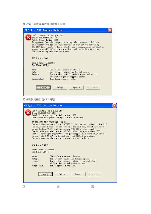
师兄第一板仿真器连接出现如下问题
然后新板连接出现如下问题
又Hale Waihona Puke 现:7.9号上午SDRAM读写正常,再次连接仿真器出现如下错误:
不知道是什么原因造成的,晶振也莫名的不起振了,折腾了半天,最后将万用表调到短路档,黑笔接地,红笔把DSP背面的滤波电容全部放电。上电后晶振起振了,仿真器连接成功,并且可以Download程序并运行,写SDRAM结果正确。
SDRAM调试结果如下:程序功能为向SDRAM中写入100个字,地址范围600002~600066,写入数据分别为1~100
液晶模块 RA8835中文操作资料

RA8835能够同时管理三到四个显示区。每个显示区都拥有自己的的显示 特性。这里将四个区定义为第一显示区L1、第二显示区L2、第三
显示区L3、第四显示区L4。RA8835以第一和第二显示区为主显示区,第三第四 显示区为辅显示区。在控制单屏结构液晶显示驱动系统时,RA8835可以分别或 同时使用第一、第二和第三显示区。在控制双屏液晶显示驱动系统时,RA8835 需要组合使用所有四个显示区。在这种情况下,第一、第二仅管理显示屏上半 屏的显示数据,第三、第四显示区管理显示屏的下半屏的显示数据,并规定第 一和第三显示区合成为一控制全屏显示,第二和第四合成为一控制全屏显示。
0.33 0.36
320240 图形点阵
Disply Format 320X240DOTS Driving Method 1/240 Duty 1/17 Bais
320240B 图形液晶显示器规格书
0.36 0.33
20
1
====================================================================================================== -2-
1) 输入高电平(Vih):0.5Vdd~Vdd 2) 输入低电平(Vil): Vss~0.2Vdd 3) 输出高电平(Voh): 2.4Vmin 4) 输出低电平(Vol): 0.4Vmax 5) 模块工作电流: <120mA (不含背光) 6) 侧白光工作电流: 140mA
====================================================================================================== -4-
基于STM32的RA8835控制器液晶显示设计
摘
要 :基 于 3 2位 的 S T M3 2处理 器 ,设计 了 R A 8 8 3 5控 制 器驱 动程 序 ,封 装 了线段 、字符 等 显
示 函数 ,实现 了液晶 图文 显示 。该方 案能绘 制任 意起 始 点、任 意 线 宽的 线段 ,能绘 制各 种 图形 ,
0 引 言
在嵌入式设备人机界面的开发中, 液 晶显示屏 的应用 较为 普遍 。利用单 片 机芯 片驱 动 L C D时 , 一
方 面编程较 为复杂 ,A 8 8 3 5硬件结 构 可分 成 MP U接 口部 、 内部 控 制 部 和驱 动 L C M 的驱 动部 。接 口部具 有 功 能较 强 的 I / / O缓 冲 器 , MP U访问 R A 8 8 3 5时不 需 判 其 “ 忙” , R A 8 8 3 5随时准 备接 收 MP U的访 问并 在 内部 时序 下 及时地 把 M P U发来 的指 令 、 数据 传输 就位 。控制 部 是 R A 8 8 3 5的核心 , 能在 很 高 的 工 作 频 率 下 迅 速 地 解 译 MP U发来的指令代码 , 控 制 部 可 以管 理 6 4 K 显示 R A M, 管理 内藏 的字符发 生 器及 外 扩 的字符 发 生器 C G R A M或 E X C G R O M。驱 动部 具 有各 显示 区
2 0 1 3 年第9 期
文章编号 : 1 0 0 9— 2 5 5 2 ( 2 0 1 3 ) 0 9— 0 1 8 6~0 3 中图分类号 : T N 9 1 1 文献标识码 : A
基于 S T M 3 2的 R A 8 8 3 5控 制器 液 晶显 示设 计
RA8835_QA_V10
RA i ORA8835Dot MatrixLCD ControllerQ&APreliminary Version 1.2July 13, 2009RA i O Technology Inc.©Copyright RAiO Technology Inc. 2009RA i O TECHNOLOGY INC. Update HistoryVersion Date Description1.0 July 13, 2009 Preliminary Version問題一:如何避免RA8835寫入或讀出資料問題?例如RA8835無法正確顯示,或者是MCU無法從display memory讀回一個正確的資料?Q1: How to avoid the writing or the reading problem of RA8835, e.g. RA8835 can not correctly display on LCM or MCU can not read from display memory an un-correct data.回覆一:LCM的顯示系統上,通常在PCB上會有一個連接MCU以及RA8835的 bus line 架構,為了避免錯誤顯示或錯誤讀寫,我們會建議在bus line上加一1K~3.3KΩ的pull-up resister來穩定bus信號。
或者,MCU interface 的cable儘量勿長於30公分。
Ans. 1: LCM display system ordinary have a bus line configuration on printed circuit boards for data communication between MCU and RA8835. To avoid the display/ the access error, we suggest that bus signals might be better stabilized by pulling up to VCC using the resistors around 1k-3.3 k or keeping the length of MCU interface less then 30CM.請參考下列相關圖示說明:Please refer to the following picture.Figure 1 Pull-up resisterFigure 2 MCU interface wire length問題二. RA8835/RA8835A 暫存器的初值為何?Q2: What are the register default values of the RA8835/RA8835A?回覆二:請參考下列圖表說明:Ans2: Please refer to the following table.Default value Class Command Hex Parameter RA8835 RA8835AP1 00H 00H P2 00H 00H P3 00H 00H P4 00H 00H P5 40H 40H P6 F0H F0H P7 00H 00H System controlSystem Set40P8 00H 00HDisplay ON/OFF58/59P1 OFF(0) ON(1) P1 00H 00H P2 00H 00H P3 00H 00H P4 00H 00H P5 00H 00H P6 00H 00H P7 00H 00H P8 00H 00H P9 00H 00H SCROLL 44P10 00H 00HP1 00H 00H CSRFORM 5D P2 00H 00HP1 00H 00H CGRAM ADR 5C P2 00H 00HCSRDIR 4C to 4F NONE 4CH 4CH HDOT SCR5AP100H00HDisplay control OVLAY 5BP1 00H 1CH P1 00H 00H CSRW 46P2 00H 00H Drawing controlCSRR 47NONE 00H 00H問題三. RA8835/RA8835A的ESD/Latch up特性為何?Q3: What are the ESD and Latch up features of the RA8835/RA8835A?回覆三:請參考下列圖表說明:Ans3: Please refer to the following table.RA8835RA8835AESD Sensitivity Pass(HBM) +4KV/-5KV,V Class-3+/-6.5KV,V Class-3Latch-up +/-200mA,IT Class-3 +/-600mA, IT Class-3問題四.在RA8835 Data sheet 版本2.0的82和83頁,這裡有兩個不同的8080時序圖,何時為其各別的使用時機。
RA8835显示程序
void DISPLAY _ON(uch ar x) {
ET0=0;
ES0=0; //片选
SFRPAG E_RAM= SFRPAG E;
SFR5=0;
wrcomm and_RA8 835(0x5 9);
//
wrdata_ RA8835( x);
//非片 选
CS_RA8 835=1;
}
/*-----------------------------------------------------------------------
OYLAY_ RA8835( )显示区及 行设置 -----------------------------------------------------------------------*/ void OYLAY_ RA8835( ) {
uchar x;
//
wrcomm and_RA8 835(0x5 b);
//p1 显示区属 性
//Bit8=0 ;
基于 C8051F 120的 RA8835 (SED13 35)的 320240 液晶屏例 程集(我 自编在用 的)
分类: 我写好的 常用的 C51程序 2008-0121 19:06 /*==== ===== ===== ===== ===== ===== ===== ===== ===== ===== ===== ===== ===== ===== ===== ==
SCROLL _RA883 5()显示 区及行设 置 -----------------------------------------------------------------------*/ void SCROLL _RA883 5() {
RAiO RA8825 128x33 LCD 驱动控制器 说明书
RA i ORA8825128x33LCD驱动控制器规格书Version 1.3July 1, 2006RA i O Technology Inc.@Copyright RAiO Technology Inc. 2005, 2006章节内容页数1. 简介 (5)2. 特性 (5)3. 系统方块图 (6)4. 脚位定义 (7)4-1 MPU 界面 (7)4-2 LCD Panel 界面 (8)4-3 Clock 与 Power 界面 (9)4-4 其它接口 (9)5. 缓存器描述 (11)5-1缓存器总表 (11)5-2 缓存器内容描述 (12)6. 功能描述 (25)6-1 微控制器接口 (25)6-1-1 并列接口 (25)6-1-2 串行接口 (26)6-1-3 缓存器读写 (27)6-1-4 内存读写 (29)6-2 内存 (31)6-3 系统频率 (31)6-4 LCD驱动器与电压供应电路 (32)6-4-1 步阶升压电路 (33)6-4-2 电压调整器电路 (34)6-4-3 电压随耦器 (35)6-4-4 LCD驱动器 (36)6-5 中断 (37)6-6 键盘扫描 (37)6-7 I/O埠 (38)6-8 冷光信号 (39)6-9 电源控制(Power Control) (39)7. 显示功能 (41)7-1 数据写入模式 (41)7-2 光标设定 (42)7-2-1 光标位置与移位 (42)7-2-2 光标显示与闪烁 (42)7-3 显示窗口 (42)7-4 水平卷动 (44)7-5 垂直卷动 (46)8. 脚位图 (47)8-1 COG Pad (47)8-2 Pad X/Y 坐标 (48)9. 电气特性 (52)9-1 Absolute Maximum Ratings (52)9-2 DC 特性 (52)9-3 Timing 特性 (53)9-3-1 并列接口 (53)9-3-2 串行接口 (54)9-3-3 Reset 界面 (56)附件A (58)A-1 COG应用 (58)A-1-1 串联接口的基本接线 (58)A-1-2 并联接口的基本接线 (59)A-1-3 其它应用的FPC接线 (60)A-2 ITO 阻值 (62)维持在Low,全部的Key Strobe信号被设为High,全部的I/O信号维持原来的设定,最后将RC振荡器关闭,因此整个IC仅耗损静态电流。
Electro-mechanical timer 882565 manual reset说明书
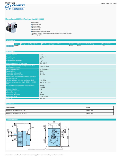
Manual reset 882565 Part number 88256508
Relay output Mono-function Mono-range Mono-voltage Manual reset Progress of cycle displayed Output : 1,2 or 3 changeover contacts (max of 16 A per contact) Mounting option
+10 % -15 % Un
3,1 VA cos φ 0,8 100 % -5→+70 -40→+80
4 G - 55 Hz 1000 V - Un ≤ 60 V 380 V AC 440 V DC IP10
6,35 250 mm 2 x M3 - 2 x M4 225 / 245
Accessories
23/06/2014
Curves 2 poles
Connections 2 poles
No
Connections 2 poles
Legend Red Blue White
Connections 2 poles
Unless otherwise specified, the characteristics given are applicable to all or part of the product range selected
23/06/2014
Dimensions (mm) Panel cut-out
Dimensions (mm)
Dimensions (mm) Inverter for DC supply 84 861 501 : 24 48 V DC 84 861 503 : 110 127 V DC Weight 150 g
- 1、下载文档前请自行甄别文档内容的完整性,平台不提供额外的编辑、内容补充、找答案等附加服务。
- 2、"仅部分预览"的文档,不可在线预览部分如存在完整性等问题,可反馈申请退款(可完整预览的文档不适用该条件!)。
- 3、如文档侵犯您的权益,请联系客服反馈,我们会尽快为您处理(人工客服工作时间:9:00-18:30)。
1
画面显示但不闪烁
0
画面以 FR/32Hz 的频率闪烁显示
1
画面以 FR/64Hz 的频率闪烁显示
4. OVLAY
OVLAY 命令字
Bit7
Bit6
Bit5
Bit4
Bit3
Bit2
Bit1
0
1
0
1
1
0
1
0x5B
OVLAY 设置参数 P1
Bit7
Bit6
Bit5
Bit4
Bit3
Bit2
Bit1
0
0
0
OV
L/F
0 1
Bit2
1
Bit1
1
Bit0
1
0xEF
位 位定义
P7 位含义
配置值
Bit7
AP 的低 8 位,虚拟屏宽度,以字节为单位, AP 取值为 C/R + 1 0
Bit6
或大于 C/R 值的整数,因为 RA8835 可以虚拟一个比液晶显示区 0
Bit5
大的 RAM 区,从而很方便的实现屏的滚动效果。我的液晶功能 1
0
1
0
1
1
0
0
D
0x58 关显示 0x59 开显示
DISP 设置参数 P1
Bit7
Bit6
Bit5
Bit4
Bit3
Bit2
Bit1
Bit0
FP5
FP4
FP3
FP2
FP1
FP0
FC1
FC0
配置为光标显示关闭,只显示一区,其他显示区关闭。以便提高清屏效率,否则全部 ram 清
零,需要耗费很长的机时 0x04
Bit6
如 320*240 的液晶,一行字符数为(320÷8-1)=39;减一是参数 0
Bit5
中会自动加一
1
Bit4 Bit3
C/R
0 0
Bit2
1
Bit1
1
Bit0
1
0x27
P5
位 位定义
位含义
配置值
Bit7
驱动频率的时间常数。TC/R 是晶振频率 Fosc 转换成液晶显示驱 0
Bit6
动 工 作 频 率 FR 的 时 间 常 数 。 它 可 以 简 单 地 由 下 式 求 出 : 0
{
ra8835CheckBusy();
RA8835_AO_LOW(); RA8835_RD_HIGH();
RA8835_DB_WRITE(data);
RA8835_WR_LOW();
//时序匹配,不然不满足最小时间要求
RA8835_WR_LOW();
RA8835_WR_HIGH();
}
/*****************************************************************************
FC 设置 FC1
FC0 光标状态
0 0 1 1
FP 设置 FP1 FP3 FP5 0 0 1 1
0
光标显示关闭
1
光标显示但不闪烁
0
光标以 FR/32Hz 的频率闪烁显示
1
光标以 FR/64Hz 的频率闪烁显示
FP0 显示一区显示状态
FP2 显示二、四区显示状态
FP4 显示三区显示状态
0
画面显示关闭
Bit0
0
1
0
1
1
1
0
1
0x5D
CSRFORM 设置参数 P1
Bit7
Bit6
Bit5
Bit4
Bit3
Bit2
Bit1
Bit0
0
0
0
0
CRX
配置为水平方向 8 个像素点 0x07
CSRFORM 设置参数 P2
Bit7
Bit6
Bit5
Bit4
Bit3
Bit2
Bit1
Bit0
CM
0
0
0
CRY
配置为垂直方向 16 个像素点 0x8F
Bit4 Bit3
APL
无需滚动效果,所以取值 40
0 1
Bit2
0
Bit1
0
Bit000x来自8P7位 位定义
位含义
配置值
Bit7
AP 的低 8 位,虚拟屏宽度,以字节为单位, AP 取值为 C/R + 1 0
Bit6
或大于 C/R 值的整数,因为 RA8835 可以虚拟一个比液晶显示区 0
Bit5
Bit0
0x87
配置值
1 0 0 0 0 1 1 1
P3
位 位定义
位含义
Bit7
0
保留位
Bit6
0
保留位
Bit5
0
保留位
Bit4
0
保留位
Bit3
字符高度,实际像素点为 FY+1
Bit2 Bit1
FY
Bit0 0x0F
配置值
1
0
0
0 1 1 1 1
P4
位 位定义
位含义
配置值
Bit7
每行的字符数,以字符为单位,实际每行字符数等于 C/R+1;例 0
Bit7
Bit6
Bit5
Bit4
Bit3
Bit2
Bit1
Bit0
0
标志位
0
0
0
0
0
0
1 为忙,0 为闲可以写入
/***************************************************************************** 函数名称:ra8835Reset 函数功能: 输入参数:无 输出参数:无 返回参数:无 *****************************************************************************/ static void ra8835Reset(void) {
RA8835_RST_LOW(); timer0ResetRa8835Count(); while(timer0GetRa8835Count() < TIMER0_40_MS); RA8835_RST_HIGH(); } /***************************************************************************** 函数名称:ra8835CheckBusy 函数功能:控制器忙状态判断 输入参数:无 输出参数:无 返回参数:无 *****************************************************************************/ static void ra8835CheckBusy(void) { RA8835_DB_IN();
Bit5
TC/R >= C/R +4,我这里采用的是液晶供应商推荐值
1
Bit4 Bit3
TC/R
1 1
Bit2
0
Bit1
1
Bit0
0
0x3A
P6
位 位定义
位含义
配置值
Bit7
液晶像素点值,如 320*240 的液晶,一列为 240-1=239,减一是 1
Bit6
参数中会自动加一
1
Bit5
1
Bit4 Bit3
DM1、DM0 设置 DM1 0 设置显示区一位字符模式,1 设置显示区一为图形模式 DM2 0 设置显示区三位字符模式,1 设置显示区三为图形模式
备注:显示区二、四为图形模式。
5. HDOT SCR
HDOT SCR 命令字
Bit7
Bit6
Bit5
Bit4
Bit3
Bit2
Bit1
0
1
0
1
1
0
1
0x5A
8. MWRITE写入显示数据
MWRITE 命令字
Bit7
Bit6
Bit5
Bit4
Bit3
Bit2
Bit1
Bit0
0
1
0
0
0
0
1
0
0x42
写入命令字后,接着写入显示数据,可连续写入多字节。1 代表显示 0 代表不显示,地址
自动按照 CSRDIR 设置的方向增加,
9. Busy标志读取
AO=0、WR=1、RD=0
Bit3 W/S 为单屏结构液晶。显示驱动系统;1 为双屏结构液晶显示驱动系
统
Bit2 M2 外部字符发生器的字体选择位。0=8*8;1=8*16
Bit1
M1
用户字符存储器选择。0 配置 CG RAM1 为 RAM,CG RAM2 配 置为 ROM,1 配置 CG RAM1 为 RAM,CG RAM2 配置为 RAM
Bit0 M0 字符发生器选择位. 0 为内部字符发生器;1 为外部字符发生器。
0x30
配置值 0 0 1 1
0
0 0 0
P2
位 位定义
位含义
Bit7 WF 交流驱动波形选择位,通常取 1
Bit6
0
保留位
Bit5
0
保留位
Bit4
0
保留位
Bit3
0
保留位
Bit2
字符宽度,实际像素点为 FX+1
Bit1 FX
晶的行数,配置为 240(0xF0):
P1
P2