PCI2362 数字量输入输出卡
戴尔PCI Express DVI(数字)适配卡安装和设置指南说明书

PCI Express DVI (Digital) Adapter Card Installation and Setup GuideThe Digital Visual Interface (DVI) adapter card, using the integrated graphics controller on your computer, provides a DVI port. The DVI port provides a direct, digital connection to a digital display, such as a digital flat panel display. The DVI adapter works through the integrated graphics on your computer and is controlled through the integrated graphics driver's user interface, which is located under the Control Panel in Microsoft ® Windows ® operating systems. The DVI adapter plugs into the PCI Express x16 slot on your system board.Safety InstructionsInstallation InstructionsTroubleshootingSpecificationsRegulatory NoticesNotes, Notices, and CautionsInformation in this document is subject to change without notice.© 2004 Dell Inc. All rights reserved.Reproduction in any manner whatsoever without the written permission of Dell Inc. is strictly forbidden.Trademarks used in this text: Dell and the DELL logo are trademarks of Dell Inc.; Microsoft, Windows , and Windows NT are registered trademarks of Microsoft Corporation; Intel is a registered trademark of Intel Corporation.Other trademarks and trade names may be used in this document to refer to either the entities claiming the marks and names or their products. Dell Inc. disclaims anyproprietary interest in trademarks and trade names other than its own.December 2004 Rev. A01NOTE: A NOTE indicates important information that helps you make better use of your computer.NOTICE: A NOTICE indicates either potential damage to hardware or loss of data and tells you how to avoid the problem.CAUTION: A CAUTION indicates a potential for property damage, personal injury, or death.1hinged lever 2filler bracket1card notch2card-clip lever 3card-clip tab 4card clip1card cage2handle3.Remove the filler bracket to create an empty card-slot opening in the card cage:a. Press the release tab at the top of the card cage.1release tab2card retention lever3card slotNOTE: See the documentation that came with the card for information on configuring the card, making internal connections, or customizing it for your computer.1DVI card2card retention lever3securing slot (not all cards)4securing tab5card connector1card cage2slots3riser boards (2)4system board connectors (2)1DVI card2card retention lever3securing slot (not on all cards) 4securing tab5card connector1card notch2card-clip lever 3card-clip tab 4card clip1card notch1hinged lever 2filler bracket1card notch2card-clip leverBack to Contents PageRegulatory Notices: PCI Express DVI (Digital) Adapter CardPCI Express DVI (Digital) Adapter Card Installation and Setup GuideFCC Notices (U.S. Only)This equipment has been tested and found to comply with the limits for a Class B digital device pursuant to Part 15 of the FCC Rules. These limits are designed to provide reasonable protection against harmful interference in a residential installation. This equipment generates, uses, and can radiate radio frequency energy and, if not installed and used in accordance with the manufacturer's instruction manual, may cause interference with radio communications.This device complies with Part 15 of the FCC Rules. Operation is subject to the following two conditions:lThis device may not cause harmful interference. l This device must accept any interference received, including interference that may cause undesired operation.Class BThis equipment has been tested and found to comply with the limits for a Class B digital device pursuant to Part 15 of the FCC Rules. These limits are designed to provide reasonable protection against harmful interference in a residential installation. This equipment generates, uses, and can radiate radio frequency energy and, if not installed and used in accordance with the manufacturer's instruction manual, may cause interference with radio communications. However, there is no guarantee that interference will not occur in a particular installation. If this equipment does cause harmful interference to radio or televisionreception, which can be determined by turning the equipment off and on, you are encouraged to try to correct the interference by one or more of the following measures:lReorient or relocate the receiving antenna. lIncrease the separation between the equipment and the receiver. lConnect the equipment into an outlet on a circuit different from that to which the receiver is connected. l Consult the dealer or an experienced radio/television technician for help.IC Notice (Canada Only)Most Dell computer systems (and other Dell digital apparatus) are classified by the Industry Canada (IC) Interference-Causing Equipment Standard #3 (ICES-003) as Class B digital devices. To determine which classification (Class A or B) applies to your computer system (or other Dell digital apparatus), examine all registration labels located on the bottom or the back panel of your computer (or other digital apparatus). A statement in the form of "IC Class A ICES-003" or "IC Class B ICES-003" will be located on one of these labels. Note that Industry Canada regulations provide that changes or modifications not expressly approved by Dell could void your authority to operate this equipment.CE Notice (European Union) Marking by the symbol indicates compliance of this product to the EMC Directive and the Low Voltage Directive of the European Union. It meets thefollowing technical standards: EN 55022 Class B and EN 55024: 1998. MIC (Republic of Korea Only)Class B DevicePlease note that this device has been approved for nonbusiness purposes and may be used in any environment, including residential areas.MIC Class B Regulatory LabelIf the regulatory label includes the following marking, your computer is a Class B product:This Class B (or Class A, if so indicated on the registration label) digital apparatus meets the requirements of the Canadian Interference-Causing Equipment Regulations.Cet appareil numérique de la Classe B (ou Classe A, si ainsi indiqué sur l'étiquette d'enregistration) respecte toutes les exigences du Reglement sur le Materiel Brouilleur du Canada.BSMI Notice (Taiwan Only)If you find a or mark on the regulatory label on the bottom, side, or back panel of your computer, the following section is applicable:Back to Contents PageBack to Contents PageSafety InstructionsPCI Express DVI (Digital) Adapter Card Installation and Setup GuideUse the following safety guidelines to help protect your computer from potential damage and to help ensure your own personal safety.When Working Inside Your ComputerBefore you open the computer cover, perform the following steps in the sequence indicated.1. Perform an orderly computer shutdown using the operating system menu.2. Turn off your computer and any devices.3. Ground yourself by touching an unpainted metal surface on the chassis, such as the metal around the card-slot openings at the back of the computer,before touching anything inside your computer.While you work, periodically touch an unpainted metal surface on the computer chassis to dissipate any static electricity that might harm internalcomponents.4. Disconnect your computer and devices from their power sources. Also, disconnect any telephone or telecommunication lines from the computer.Doing so reduces the potential for personal injury or shock.In addition, take note of these safety guidelines when appropriate:lWhen you disconnect a cable, pull on its connector or on its strain-relief loop, not on the cable itself. Some cables have a connector with locking tabs; if you are disconnecting this type of cable, press in on the locking tabs before disconnecting the cable. As you pull connectors apart, keep them evenly aligned to avoid bending any connector pins. Also, before you connect a cable, make sure both connectors are correctly oriented and aligned. l Handle components and cards with care. Do not touch the components or contacts on a card. Hold a card by its edges or by its metal mounting bracket. Hold a component such as a microprocessor chip by its edges, not by its pins.Protecting Against Electrostatic DischargeStatic electricity can harm delicate components inside your computer. To prevent static damage, discharge static electricity from your body before you touch any of your computer's electronic components, such as the microprocessor. You can do so by touching an unpainted metal surface on the computer chassis. As you continue to work inside the computer, periodically touch an unpainted metal surface to remove any static charge your body may have accumulated. You can also take the following steps to prevent damage from electrostatic discharge (ESD):lWhen unpacking a static-sensitive component from its shipping carton, do not remove the component from the antistatic packing material until you are ready to install the component in your computer. Just before unwrapping the antistatic packaging, be sure to discharge static electricity from your body. lWhen transporting a sensitive component, first place it in an antistatic container or packaging. l Handle all sensitive components in a static-safe area. If possible, use antistatic floor pads and workbench pads.Back to Contents PageCAUTION: Do not attempt to service the computer yourself, except as explained in your online Dell documentation or otherwise provided to you. Always follow installation and service instructions closely.NOTICE: To help avoid possible damage to the system board, wait 5 seconds after turning off the computer before removing a component from the system board or disconnecting a device from the computer.CAUTION: There is a danger of a new battery exploding if it is incorrectly installed. Replace the battery only with the same or equivalent type recommended by the manufacturer. Discard used batteries according to the manufacturer's instructions.Back to Contents PageTroubleshooting: PCI Express DVI (Digital) Adapter CardPCI Express DVI (Digital) Adapter Card Installation and Setup Guide1.If the computer detects the card and lists it in the Device Manager, ensure that the advanced graphics setting and options on the Intel® GMA DriverControl Panel are set correctly for the video configuration that you want.2.Verify proper connection between the monitor video cable and the DVI card port.3.Attach a CRT monitor to the VGA connection to ensure that the system is producing a video signal using the integrated controller.4.If the monitor is capable of both VGA and DVI input, ensure that the input selector on the monitor is set correctly.5.If the card is not properly detected, reseat the DVI card in the PCI Express x16 slot to ensure a good connection.See the Installation Instructions.6.If available, test the DVI card by installing the card into a same-model system with a properly working PCI Express x16 slot.7.If available, place a properly working DVI card in the computer to test the PCI Express x16 slot.Back to Contents Page。
高速模拟量输入数据采集卡

支持的操作系统 Windows 98/2000/NT/XP/Linux
推荐软件 VB/VC++/BCB/DelphiCVI, Mathlab
驱动支持 用于Windows98/2000/NT/XP的DLL
概述
PCI-3160是一个低成本的高速数据采集卡,板上集成16M(64MB可选)和32位143MHz的DSP处理器,提供足够长的模拟信号数据绝无数据 丢失。提供4个同步模拟信号输入端口,和宽电压输入范围。PCI-3160是理想的通讯应用比如:通讯数据分析。40MS/s采样率,在板的RAM和 DSP处理可以作为理想的无数据丢失的记录仪。具有12位的精度,高速数据采集,灵活的触发方式,是高速数据采集的理想产品。在板的DSP 处理器可预处理密集的数据,比如:FFTs和数据过滤,释放主机作为更高级的算法和控制。外部的时钟和触发特点允许多块卡在同一个系统主机 下。PCI-3160是PCI的Plug-and-Play,数字自动校准技术,板上没有跳线和电位器。
PCI 高速模拟量输入数据采集卡
PCI-3160
4通道40MHz同步模拟量输入数据采集卡
特性
4通道模拟量输入 每通道40 MS/s A/D转换 12 Bit A/D 分辨率 16 MB 缓存 模拟量,数字量,软件触发方式 在板DDS提供1Hz的采样时钟 16通道数字量DIO,任意选择输入输出 2路计数器/定时器 143MHz,32位的DSP处理器
级别:256个台阶 斜坡:+ or 外部:±4V, 100kΩ Zin, 50 ns min脉冲带宽 采样速率:内部时钟: 10k to 40MS/s(1Hz精度)单通道
10k to 20MS/s(1Hz精度)双通道 10k to 10MS/s(1Hz精度)满通道 软件控制 独立的输出时钟 外部时钟: >=4x采样速率输入或输出100kΩ Zin,80MHz最大 存储器:16MB(64MB可选) PCI:32bit,33 MHz总线连续控制,全速80MB/s到PC存储器
PCI-8333 多功能模入模出接口卡技术说明书
PCI-8333多功能模入模出接口卡技术说明书1.概述PCI-8333多功能模入模出接口卡适用于提供了PCI总线插槽的PC系列微机,具有即插即用(PnP)的功能。
其操作系统可选用目前流行的Windows系列、高稳定性的Unix等多种操作系统以及专业数据采集分析系统LabVIEW等软件环境。
在硬件的安装上也非常简单,使用时只需将接口卡插入机内任何一个PCI总线插槽中并用螺丝固定,信号电缆从机箱外部直接接入。
PCI-8333多功能模入模出接口卡安装使用方便,程序编制简单。
其模入模出及I/O信号均由卡上的37芯D型插头与外部信号源及设备连接。
对于模入部分,用户可根据实际需要选择单端或双端输入方式。
对于模出部分,用户可根据控制对象的需要选择电压或电流输出方式以及不同的量程。
本卡上的A/D、D/A 转换均为12位,同时还备有16路数字量输入和16路数字量输出接口,三路16位字长的计数/定时器,以及1Mhz的基准时钟。
本卡的A/D转换启动方式可以选用程序触发、定时器自动触发、外同步触发等方式,转换状态可以用程序查询,也可以用中断方式通知CPU读取转换结果。
2.主要技术参数2.1模入部分:2.1.1输入通道数:单端16路*(标*为出厂标准状态,下同)双端8路2.1.2输入信号范围:0V~10V*;-5V~+5V2.1.3输入阻抗:≥10MΩ2.1.4A/D转换分辨率:12位2.1.5A/D转换速度:10μS2.1.6A/D启动方式:程序启动/定时触发启动/外触发启动2.1.7A/D转换结束识别:程序查询/中断方式2.1.8A/D转换非线性误差:±1LSB2.1.9A/D转换输出码制:单极性原码*/双极性偏移码2.1.10系统综合误差:≤0.1% F.S2.2模出部分:2.2.1输出通道数:2路2.2.2输出范围:电压方式:0~5V;0~10V*;-5V~+5V;-2.5V~+2.5V;+1V~+5V电流方式:0~10mA;4~20mA2.2.3输出阻抗:≤2Ω(电压方式)2.2.4D/A转换分辨率:12位2.2.5D/A转换输入码制:二进制原码(单极性输出方式时)*二进制偏移码(双极性电压输出方式时)2.2.6D/A转换综合建立时间:≤2μS2.2.7D/A转换综合误差:电压方式:≤0.1% F.S电流方式:≤0.5% F.S2.2.8电压输出方式负载电流:≤5mA2.2.9电流输出方式负载电阻范围:使用机内+12V电源时:0~250Ω外加+24V电源时:0~750Ω2.3数字量输入输出部分:2.3.1DI:16路/DO:16路;TTL电平2.4定时/计数器部分:2.4.116位字长计数/定时器:3路2.4.2基准时钟:1MHz,占空比50%2.5电源功耗:+5V(±10%)≤800mA+12V(±10%)≤50mA(D/A电流方式输出,并使用机内电源时)2.6使用环境要求:工作温度:10℃~40℃相对湿度:40%~80%存贮温度:-55℃~+85℃2.6外型尺寸:(不含档板)外型尺寸(不含档板):长×高=175.0mm×106.7mm(6.89英寸×4.2英寸)3.工作原理PCI-8333模入模出接口卡主要由模数转换电路、数模转换电路、数字量输入输出电路,定时/计数器电路和接口控制逻辑电路构成。
PCL-812PG卡说明
PCL-812PG多功能数据采集卡使用说明书第一章概述这一章介绍PCL-812PG的背景信息包括关键特性、扩展性能、产品说明书1.1绪论PCL-812PG 是IBM PC/XT/AT及其兼容机的高性能、高速、多功能数据采集卡。
整卡的详尽说明书及齐全的第三方卖主的软件支持是PCL-812PG广泛的应用于工业及实验室环境下。
主要应用于数据采集、过程控制、自动检测、工厂自动控制。
1.2关键特性。
16位单端模拟输入通道。
一个工业标准的12位逐位逼近式A/D转换器(HADC574Z)用于转换模拟量输入。
在DMA模式下最大的A/D采样速率为30KHz。
软件可编程模拟输入序列。
双极性电压+/- 5V, +/- 2.5 V, +/- 1.25V +/- 0.625 V +/- 0.3125 V。
三种A/D触发模式。
软件触发器。
可编程步测触发器。
外部脉冲触发器。
程序控制A/D转换器的数据传输,中断处理器或DMA转换。
一个Intel 8253-5可编程定时器/计数器可提供以0.5 MHz-35minutes/pulse步测输出(触发脉冲),定时器的时间基准为2 MHz。
一个16位计数器保留给用户设置应用。
两个12位单集成多极性D/A输出通道。
一路输出可由板内-5V或-10V参考电压产生0-5V 或0-10V范围的输出。
这个参考电压精度来源于A/D转换器的参考电压精度。
外部直流或交流参考电压同样也可以用于产生其它D/A 输出。
16位TTL/DTL兼容数字输入、输出通道1.3 扩展性能为了增强PCL-812PG功能,可以通过以下可选子卡来扩展其功能。
PCLD-789放大器/乘法器卡这个功能强的前置模拟信号调理卡能在一个A/D输入通道中多路传输16路信号。
高级的仪表化的放大器提供开关选择增益,分别为0.5, 1, 2, 10, 50, 100, 200, 1000或任何用户自定义。
PCLD-787八通道同步采样保持前置卡该卡允许在小于30 ns通道间采样时间偏差下进行八通道模拟信号的同步采集。
现场总线接口卡
DP-V1、PROFIBUS DP-V2 – 主站、从站和 PROFIBUS
监控,传输速率可达 12 Mbit/s – 功能强大的参数和诊断接 口 – 每个总线用户的故障管理 可自由配置 – 可以读取总线配置并自动 分配“GSE”文件 – 可扩展为 32 KB NOVRAM
标准配置
fc510x-0002
配置为 32 KB NOVRAM
627
技术规格若有变更,恕不另行通知。
BeckhofF 自动化新技术
fc5201, fc5202
FC5201, FC5202 | PcI DeviceNet 总线接口卡
FC5201 和 FC5202 PC 插卡可以 将 PC 连接到 DeviceNet 网络 中。它们既可用作网络主站 模块,也可用作从站模块。 PCI 总线接口卡确保数据高速 传输至 PC,插卡可在 PC 硬 件中全自动配置。DeviceNet 插卡提供功能强大的协议实 现和诸多功能: – 支持所有 DeviceNet I/O 模
和驱动程序
636
以太网交换机
638
CU2008(8 端口)
639
CU2016(16 端口)
PC 现场总线接口卡,交换机
623
BeckhofF 自动化新技术
Pc 现场总线接口卡
带有 PCI 总线接口的现场总线 PC 接口卡
PC 现场总线接口卡 基于 PCI 的 PC 现场总线接口卡 适用于 Lightbus、PROFIBUS、 CANopen、DeviceNet、SERCOS interface 和以太网系统,这一 的系列总线接口卡进一步完 善了 Beckhoff 现场总线组件产 品,专为快速控制和实时任务 (如驱动器位置控制)而开 发,因而得到广泛的应用。为 了适应不同的需求,接口卡都 配有一个或两个现场总线通 道。以太网接口卡 FC9004 总 共有 4 个通道。若将这种功能 强大的 PC 现场总线接口卡与 TwinCAT 软件 PLC 和 NC 结合 起来,其功能优势是显而易见 的。这种智能化 PCI 接口卡是 在其自身的处理器上高效处理 现场总线协议,因此也可用于 其它应用场合。通过 DPRAM 接口可将过程映像传送到 PC 上。TwinCAT I/O 软件包可提供 用于 Windows NT/2000/XP/Vista 的驱动程序和配置工具。用高 级语言编写的程序采用的是 DLL(动态连接库),对 Visual Basic 应用程序则可提供 ActiveX 接口。带有 OPC 接口的应用程
PCI-8602 多功能 DA 输出卡 说明书
PCI-8602多功能DA输出卡使用说明书2004/02一 概述PCI-8602是一款PCI总线多功能DA输出卡,为用户提供了4路模拟信号输出通道 ,2路反相的PWM数字信号输出通道 , 10Bit TTL数字量输入通道,10Bit TTL数字量输出通道,24bit(OPTO-22兼容) 数字量输入/输出通道。
二、性能和技术指标2.1 性能• 4路模拟信号输出通道• 模拟信号输出分辩率16Bit• 模拟信号输出范围[-10 , +10]V• PWM输出可调范围14bit• PWM输出可调精度0.1uS• 2路PWM反相输出• 10Bit DI TTL兼容数字量输入• 10Bit DO TTL兼容数字量输出• 24bit(82C55A)数字量输入/输出通道• 一路数字量输入上升沿中断2.2模拟信号输出技术指标• 模拟信号输出通道: 4• 模拟信号输出分辨率 16位• 模拟信号输出范围: ±10 V• 数模转换器件 DAC7744• 建立时间: 10uS• 精度: 优于±0.003%满量程• 线性度: ± 1/2 LSB• 复位状态: 0输出• 输出负载能力: ±5mA2.3 PWM 输出• PWM输出通道: 2路反相• 脉冲周期范围: 0.1uS – 1.6384mS• 高电平输出范围: 0.0uS – 1.6384mS• 分辨率 0.1uS• 建立时间: 1uS• 输出电平: TTL兼容• 低电平输出: 灌电流8mA时,最大输出0.5 V • 高电平输出 源电流0.05mA时,最小输出2.4V • 复位输出 PWMA 输出0 ,PWMB输出12.4 数字量输出• 通道: 10路• 输出电平: TTL兼容• 低电平输出: 灌电流8mA时,最大输出0.5 V • 高电平输出 源电流0.05mA时,最小输出2.4V • 复位输出 输出02.5 数字量输入• 通道: 10路• 输入电平: TTL兼容• 低电平输入: 最大0.8V• 高电平输入 最小2.0V2.6 数字量输入/输出• 结构 82C55A• 兼容 OPTO-22• 通道: 24路• 输入电平: TTL兼容• 低电平输入: 最大0.8V• 高电平输入 最小2.0V2.7 数字量中断• 通道: 1路• 引脚: DI9(共用)• 输入电平: TTL兼容• 低电平输入: 最大0.8V• 高电平输入 最小2.0V• 方式: 上升沿三、引脚描述3.1 CN1模拟量输出引脚 : AO(0..2)数字量输出引脚 : DO(0..11)数字量输入引脚 : DI(0..11)PWM 输出引脚 : PWMA ,PWMB数字地 : DGND模拟地 : AGND中断输入 : DI93.2 辅助数字量引脚CN282C55端口A : PA82C55端口B : PB82C55端口C : PC数字地 : DGND四.寄存器描述;本章描述了PCI8602所用的寄存器,如果你对PCI设备编程比较熟悉,或者你是非windows平台的客户,你可以使用这些寄存器直接对PCI8602编程。
【价格】开关量控制卡 光隔离数字量输出卡)系列)图
【价格】开关量控制卡光隔离数字量输出卡)系列)图PCI2316是一块64路光电隔离开关量输出板。
软件支持:下列软件可将使您的开发更加方便、快捷。
差不多硬件治理函数库使用例程(Dos、Win9x/NT/2000/XP)技术特点64路(共地)开关量输出通道(光电隔离)。
数字输出与PC机完全隔离,隔离耐压>1000Vdc 。
PCI总线接口,接口芯片为PLX9052。
用户接口:37芯D型插头、40芯插头;OC输出(集电极开路输出)。
OC输出指输出为无源下拉形式,即输出在高电平常表现为输出为高内阻状态。
低电平常输出对地线为低内阻状态(近似对地短路)。
输出建立时刻小于100微秒最大输出电流:大于15mA/路(压降小于1V)能够直截了当驱动PCI2603大功率继电器端子板应用领域工业操纵性能指标通道数:64路输出(光电隔离)隔离电压:大于等于1000Vdc输出信号最高切换频率10kHz(方波)其他指标用户接口:37芯D型插头、40芯双排插头工作温度:0℃~55℃储存温度:-20~80℃湿度:40~90%电源:+5V尺寸:169mm X 92mm第二章安装本章将描述PCI2316的安装和配置,请认真阅读以下内容。
2.1 产品组成包装内应包括以下物品:PCI2316接口板光盘一张,上面包括产品37芯针壳,40芯压线头。
如有物品丢失或损坏,请赶忙与销售商联系。
2.2 PCI2316的布局PCI2316的布局参见附录4。
2.3 用户连接器(1) PCI2316板的后32通道开关量(DO32~DO63)通过37芯D型插座XS1与外部连接。
37芯D型插座的连线如下表所示:37芯管脚号管脚定义管脚号管脚定义1 DO32 20 DO332 DO34 21 DO353 DO36 22 DO374 DO38 23 DO395 DOGND1 24 DO406 DO41 25 DO427 DO43 26 DO448 DO45 27 DO469 DO47 28 DOGND110 DO48 29 DO4911 DO50 30 DO5112 DO52 31 DO5313 DO54 32 DO5514 DO56 33 DOGND115 DO57 34 DO5816 DO59 35 DO6017 DO61 36 DO6218 DO63 37 DOGND119 DOV1讲明:DO32~DO63为32路开关量输出信号,DOV1 为外接公共电源,DOGN D1为公共地。
National Instruments PCI-6221 多功能数字输入输出板说明书
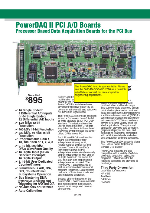
ߜ16 Single Ended/8 Differential A/D Inputsor 64 Single Ended/32 Differential A/D Inputs ߜ1.25 MS/s 12-bitResolutionߜ400 kS/s 14-bit Resolution ߜ333 kS/s, 50 kS/s 16-bit ResolutionߜProgrammable Gain 1, 10, 100, 1000 or 1, 2, 4, 8ߜ2, 12-bit, 200 kHzD/A’s WaveForm Quality ߜ16 Digital Input (8 Can Generate Interrupts)16 Digital Outputߜ3, 16-bit User-Dedicated Counter/TimersߜSimultaneous A/D, D/A, DIO, Counter/TimerSubsystems Operation ߜBus Mastering DMAExtensive Clocking andTriggering for A/D and D/A ߜNo Jumpers or Switches ߜAuto CalibrationPowerDAQ II boards have been developed with new “clean” 32-bit drivers for Windows95 and Windows NT, hence no legacy code.The PowerDAQ II series is designed around a “processor based” 24-bit 66 MHz Motorola 56301 PCI DSP interface. This design allows the user to offload the host CPU data acquisition functions to the onboard DSP thus giving the user the power of two CPUs in one PC.Each PowerDAQ II multifunction board is comprised of four subsystems, Analog Input, Analog Output, Digital I/O and Counter/Timers. PowerDAQ technology allows all the subsystems to run simultaneously and/or independently with one or multiple boards in the same PC. You can start and stop multiple subsystems as required. The PowerDAQ II based boards all feature extensive hardware and software triggering. Data transfer methods include slave mode and bus mastering operation.Several different models of the PowerDAQ II boards are available. The models differ in resolution, speed, input range and numberof channels.PowerDAQ II PCI A/D BoardsProcessor Based Data Acquisition Boards for the PCI BusBasic Unit$895provided at no additional charge.The suite consists of a menu drivenquick start application for quick andeasy operation without programming,a software development kit (SDK) forcustom user program creation underWindows 9x/NT/2000 and softwaredrivers for a large variety of off-the-shelf applications. The quick startapplication provides data collection,graphical display of the data, anddatalogging in a format compatiblewith most spreadsheets and otherpost acquisition software packages.The PowerDAQ SDK supports VisualC++, Visual Basic, Delphi andBorland C++ BuilderPowerDAQ II boards are alsocompatible with a variety of off-the-shelf data acquisition applicationprograms. The drivers for thefollowing packages are provided atno charge.Third Party Drivers for:LabVIEW for WindowsHP VEETestPointDASYlabDIAdemD1-23D1-24D1ANALOG INPUT AND MULTI-FUNCTION CARDSAccessory RacksThe PowerDAQ II boards canconnect to a variety of stand-alone or 19" rack-mount accessory panels. A complete range of cables and options are availabl HIsolated Thermocouple Input Rack The PD-TCR-16-x is a 16 channel isolated thermocouple rack which can be connected to any PowerDAQ II board. The thermocouple rack supports measurement from J or K thermocouples.For 16 channels of measurement,the PowerDAQ II boards may beconnected directly to thePD-TCR-16-x via a PD-CBL-96(96-way pinless 1 m cable). For more than 16 channels, the PD-5BCONN interface panel should be used(see diagram).Features of the PD-TCR-16• Support Type J (Iron-Constantan)or Type K (CHROMEGA ®-ALOMEGA ®) direct input connection • CJC on each channel• Laser wafer trimmed to 1°C calibration accuracy• Individual channel isolation to 1000 V • Type J input: 0 to 600°C • Type K input: 0 to 1000°C• Up to 64 Non multiplexed inputs per systemLabVIEW and Thermocouple Rack screen shownSignal Conditioning Connection PanelsThe PD-5BCONN and PD-7BCONN signal conditioning interface panels provide easy connection to up to four signal conditioning racks. ThePD-5BCONN connects to OMEGA’sOM5 signal conditioning racks and the PD-TCR-16-x isolated thermocouple input rack. The PD-7BCONN connects to OMEGA’s OM7 signal conditioning racks.Screw Terminal Panels Two screw terminal boards are available, the PD-STP-9616connects to 16 channel PowerDAQ II boards and the PD-STP-96 connects to boards with 64 channels. Use the PD-CBL-96one meter cable to connect from the PowerDAQ II J1 analog connector to the PD-STP J1 connector. Use the PD-CBL-37 ribbon cable set to PD-STP J2 connector.BNC Analog Connection PanelThe PD-BNC-16 offers all analog input connections using BNC type connectors for the 16 channelboards. The PD-BNC-16 supports single ended or differential input (via jumper selection). Silk screened component open locations for building RC filters and voltage dividers are also supplied. The PD-BNC-16 panel connects to the 16 channel PowerDAQ II boards using the PD-CBL-96 cable. The PD-BNC can be rack mounted using the PD-19RACK option.All PowerDAQ II boards include a complete user’s manual, Quick Start application and driver software.Ordering Example:PD2-MF-16-150/16L PowerDAQ II board, PD-STP-9616-KIT accessory kit and OMEGACARE SM 1 year extended warranty for PowerDAQ II board (adds 1 year to standard 1 year warranty), $895 + 275 + 89 = $1259.D1-25PD-7BCONN Interface PanelPD-5BCONN Interface PanelConnecting to Four OM5 Backplanes or Four PD-TCR16 Thermocouple RacksPD-STP Screw Terminal PanelsSpecificationsANALOG INPUTNumber of Channels:16 or 64 single-ended, 8 or 32 differential Resolution:PD2-MF-xx-400/14x:14 bits PD2-MF-xx-1M/12x:12 bits PD2-MF-xx-150/16x:16 bits PD2-MF-xx-333/16x:16 bits Max Sample Rate:PD2-MF-xx-400/14x:400 kS/s PD2-MF-xx-1M/12x:1.25 MS/s PD2-MF-xx-150/16x:150 kS/s PD2-MF-xx-333/16x:333 kS/s Onboard FIFO:1K FIFO, upgradeable to 16K or 32K Input Ranges:0-10 V, ±10 V, 0-5 V, ±5 V (software selectable)Programmable Gains:L Versions = 1, 10, 100, 1000; H Versions = 1, 2, 4, 8 (software selectable)Max Working Voltage(signal plus common mode): All Models: -10 V to 10 VInput Overvoltage:-35 V to +55V continuous, powered or unpowered Nonlinearity:PD2-MF-xx-400/14x:±0.5 LSB PD2-MF-xx-1M/12x:±0.5 LSB PD2-MF-xx-150/16x:±1 LSB PD2-MF-xx-333/16x: ±1 LSB System Noise:PD2-MF-xx-400/14x:±0.2 LSB PD2-MF-xx-1M/12x:±0.8 LSB PD2-MF-xx-150/16x:±1.2 LSB PD2-MF-xx-333/16x:±1.3 LSBInput Impedance:10 M Ωin parallel with 22 pFInput Bias Current:±20 nA typical Input Offset Current:±100 pA typical Triggering Modes:Normal, Post,Pre and About Trigger ANALOG OUTPUTNumber of Channels:2Resolution: 12 bitMax Update Rate: 200 kS/s Range:±10V fixed Data Transfer:DMA DIGITAL I/OInput/Output Bits:16Input High:V IH ≈2.0VInput Low:V IL ≈0.8V Input Current:I IH ≈20 mA,I IL ≈-20 mAOutput High:V OH ≈3.0VOutput Low: V OL ≈0.5V COUNTER/TIMERNumber of Counters:3 available to userResolution: 16 bitsInput Low:V IL=0.8V max;I IL= -20 μA maxInput High:V IH=2.0V max;I IH= 20 μA max Connector 2:36-pin header connector (male)Connector 4:36-pin header connector (male)Connector 6:Power Requirements:5W typicalDimensions:10.5 x 3.8" (262 x 98 mm)CANADA www.omega.ca Laval(Quebec)1-800-TC-OMEGA UNITED KINGDOM Manchester,England0800-488-488GERMANY www.omega.deDeckenpfronn,Germany************FRANCE www.omega.fr 088-466-342BENELUX www.omega.nl 0800-099-33-44UNITED STATES 1-800-TC-OMEGA Stamford,CT.CZECH REPUBLIC www.omegaeng.cz Karviná,Czech Republic596-311-899TemperatureCalibrators, Connectors, General Test and Measurement Instruments, Handheld Instruments for Temperature Measurement, Ice Point References, Indicating Labels,Crayons, Cements and Lacquers, Infrared Temperature Measurement Instruments, Recorders, Relative Humidity Measurement Instruments, PT100 Probes, PT100 Elements,Temperature & Process Meters, Timers and Counters,Temperature and Process Controllers and Power Switching Devices, Thermistor Elements, Probes and Assemblies,Thermocouples, Thermowells and Head and WellAssemblies, Transmitters, Thermocouple Wire, RTD ProbesPressure,Strain and ForceDisplacement Transducers, Dynamic Measurement Force Sensors, Instrumentation for Pressure and StrainMeasurements, Load Cells, Pressure Gauges, PressureReference Section, Pressure Switches, Pressure Transducers,Proximity Transducers, Regulators, Pressure Transmitters,Strain Gauges, Torque Transducers, ValvespH and ConductivityConductivity Instrumentation,Dissolved OxygenInstrumentation,Environmental Instrumentation,pH Electrodes and Instruments,Water and Soil Analysis InstrumentationHeatersBand Heaters,Cartridge Heaters,Circulation Heaters,Comfort Heaters,Controllers,Meters and SwitchingDevices,Flexible Heaters,General Test and Measurement Instruments,Heater Hook-up Wire,Heating Cable Systems,Immersion Heaters,Process Air and Duct,Heaters,Radiant Heaters,Strip Heaters,Tubular HeatersFlow and LevelAir Velocity Indicators,Doppler Flowmeters,LevelMeasurement,Magnetic Flowmeters,Mass Flowmeters,Pitot Tubes,Pumps,Rotameters,Turbine and Paddle Wheel Flowmeters,Ultrasonic Flowmeters,Valves,Variable Area Flowmeters,Vortex Shedding FlowmetersData AcquisitionAuto-Dialers and Alarm Monitoring Systems,Communication Products and Converters,Data Acquisition and Analysis Software,Data LoggersPlug-in Cards,Signal Conditioners,USB,RS232,RS485and Parallel Port Data Acquisition Systems,Wireless Transmitters and Receivers。
PCI、PCI-X、PCI-E光纤网卡插槽的性能比较
PCI、PCI-X、PCI-E光纤网卡插槽的性能比较Macnet7210PF PCI千兆光纤网卡(LC接口)Macnet8210PF PCI-X千兆光纤网卡(SC接口)Macnet9210PF PCI-E千兆光纤网卡(SC接口)以上述三种不同的光纤网卡为例,分析PCI、PCI-X、PCI-E光纤网卡插槽的性能PCI Express ,是全新第三代输入/输出(I / O)的标准,相比较过去的PCI和PCI扩展PCI – X电脑和服务器插槽,它可以卓越提高以太网网络性能,PCI Express的卓越性能来自于它更快,相对于速度较慢的133 - MHz的PCI - X的并行总线,它采用串行总线结构,提供了一个专用的2.5 GHz的时钟的双向I / O。
这本白皮书提供了新的PCI Express总线架构概述以及它带给台式机,工作站和服务器的以太网连接的优势。
目录PCI Express *以太网 (1)摘要 (2)介绍 (2)PCI,PCI – X到PCI Express---一个自然演进过程 (2)图 1 PCI,PCI - X和PCI Express的每帧带宽比较 (3)PCI Express的基础知识 (3)图 2 PCI Express * x1通道。
两个PCI Express设备(设备A和设备B)之间通道包含两个差分驱动信号。
(4)表 1 各种PCI Express通道实现的带宽 (4)图3通过PCI Express高速串行总线I/O实现千兆以太网到桌面 (5)图 4 服务器/工作站系统的PCI Express *范例 (6)网卡更高性能和可管理性增强 (7)结论 (7)1摘要随着网络流量需求不断增加,当前使用多点的(PCI)总线架构以及它的第二代版本PCI扩展PCI-X总线中瓶颈是不可避免的,。
现今,这些瓶颈可在第三代的PCI Express *架构得到缓解,PCI-E架构它使用 2.5 GHz的串行输入/输出(I/ O)的结构,以提供更高的带宽以及更好的可扩展性. 这本白皮书提供了新的PCI Express总线架构概述以及它带给台式机,工作站和服务器的以太网连接的优势。
wd无敌系列卡pci 总线rs232 扩展卡 说明书
WD(无敌)系列卡PCI总线 RS232 扩展卡用户手册目录一、 性能指标二、 软件支持环境三、 硬件安装3.1、在Windows95/98/Me/2000/XP下安装3.2、WindowsNT4.0串口设备安装3.3、SCO Unix3.2/5.0.5安装3.4、在SCO Unix 下安装调制解调器(MODEM)3.5、在Linux 下安装WD系列多用户卡四、 注意事项五、 产品清单欢迎您选购本公司的WD(无敌)系列卡。
本系列产品使用高性能的通信芯片,每个端口收发各有128字节FIFO,由PCI总线扩展2,4,8,16,32,64个RS232口。
一、 性能指标1. 符合PCI2.1规范2. I/O地址和中断由PC BIOS自动分配3. 端口数量:a. WD-100 为 2 个串口,并口符合IEEE1284规范b. WD-200 为 4 个串口,并口符合IEEE1284规范c. WD-400 为 8 个串口,并口符合IEEE1284规范d. WD-800 为16个串口,并口符合IEEE1284规范4. Windows95/98/Me/2000/XP,Windows NT4.0系统可支持多块WD(无敌)系列卡。
5. 端口数据信号:a. WD-100/200为TX,RX,RTS,CTS,DTR,DSR,DCD,RI,GNDb. WD-400/800为TX,RX,RTS,CTS,DTR,DSR,DCD,GND6. 端口属性(Windows 95/98/Me/2000/XP)a. 端口速率:正常为115.2Kbpsb. 芯片模式可选择:16C450或16C550或16C950,使用16C950时,收发各128字节的FIFO。
并且端口FIFO数量可调整,FIFO中断触发水平可调整。
c. 数据位长度:5,6,7,8d. 校验方式:None,Even,Old,Space,Marke. 停止位长度:1,1.5,2f. 数据流控制方式:None,RTS/CTS,DTR/DSR,Xon/Xoff7. 每个端口的数据信号都有过压保护装置,可防止静电打坏端口8. 为了驱动程序的稳定性和耐用性,驱动程序可能会用CD-R光盘形式配送的,而非软盘。
凌华科技推出PCI接口16位高线性度模拟输出卡
凌华科技推出PCI接口16位高线性度模拟输出卡
佚名
【期刊名称】《微计算机信息》
【年(卷),期】2008(24)18
【摘要】亚洲最大的数据采集产品供货商-凌华科技推出高线性度、16位高分辨率、每通道更新速度每秒高达1MS的PCI接口模拟输出卡PCI-6202,特别适用在动态信号仿真、激光雕刻及伺服控制等需要高精度输出的应用。
【总页数】1页(P330-330)
【关键词】PCI接口;高线性度;凌华科技;输出卡;模拟;数据采集;高分辨率;更新速度【正文语种】中文
【中图分类】TP334.7;TP213
【相关文献】
1.凌华科技推出高分辨率PCI规格的数字化仪系列产品PCI-9816、PCI-9826以及PCI-9846——凌华科技积极扩充高分辨率数字化仪产品线,PCI-9816/9826/9846系列提供高精度、低噪音及高动态范围性能 [J], 无
2.凌华科技推出适用于机器视觉应用的高速数字图像采集卡——采用PCI Express 总线、双端口IEEE1394.b接口具备线缆固定功能 [J], 无
3.PCI接口16位高线性度模拟输出卡 [J],
4.凌华科技推出24位高精度PCI接口数据采集卡 [J],
5.凌华科技推出高线性度模拟输出卡 [J],
因版权原因,仅展示原文概要,查看原文内容请购买。
阿尔泰 PCI8622数据采集卡 硬件说明书
PCI8622数据采集卡硬件使用说明书北京阿尔泰科技发展有限公司产品研发部修订北京阿尔泰科技发展有限公司目录目录 (1)第一章功能概述 (1)第一节、产品应用 (1)第二节、AD模拟量输入功能 (1)第三节、DI数字量输入功能 (2)第四节、DO数字量输出功能 (2)第五节、CNT定时/计数器功能 (2)第六节、其他指标 (2)第二章元件布局图及简要说明 (3)第一节、主要元件布局图 (3)第二节、主要元件功能说明 (3)一、信号输入输出连接器 (3)二、电位器 (3)三、物理ID拨码开关 (3)四、状态灯 (4)第三章信号输入输出连接器 (5)第一节、信号输入输出连接器定义 (5)第二节、DI数字量信号输入连接器定义 (6)第三节、DO数字量信号输出连接器定义 (6)第四章各种信号的连接方法 (8)第一节、AD模拟量输入的信号连接方法 (8)一、AD单端输入连接方式 (8)二、AD双端输入连接方式 (8)第二节、DI数字量输入的信号连接方法 (9)第三节、DO数字量输出的信号连接方法 (9)第四节、时钟输入输出和触发信号连接方法 (9)第五节、多卡同步的实现方法 (10)第五章数据格式、排放顺序及换算关系 (12)第一节、AD模拟量输入数据格式及码值换算 (12)一、AD双极性模拟量输入的数据格式 (12)二、AD单极性模拟量输入数据格式 (12)第二节、AD单通道与多通道采集时的数据排放顺序 (12)一、单通道 (12)二、多通道 (12)第六章各种功能的使用方法 (14)第一节、AD触发功能的使用方法 (14)一、AD内触发功能 (14)二、AD外触发功能 (14)第二节、AD内时钟与外时钟功能的使用方法 (16)一、AD内时钟功能 (16)二、AD外时钟功能 (16)第三节、AD连续与分组采集功能的使用方法 (16)一、AD连续采集功能 (16)二、AD分组采集功能 (16)PCI8622数据采集卡硬件使用说明书版本:6.1.18第七章 CNT定时/计数器功能 (20)第一节、功能概述 (20)第二节、计数器方式 (20)一、简单计数和时间测量功能 (20)二、缓冲计数和时间测量功能 (23)第三节、脉冲发生器方式 (25)一、脉冲发生器输出类型 (25)二、脉冲发生器功能 (26)第八章产品的应用注意事项、校准、保修 (30)第一节、注意事项 (30)第二节、AD模拟量输入的校准 (30)第三节、保修 (30)附录A:各种标识、概念的命名约定 (31)北京阿尔泰科技发展有限公司第一章功能概述信息社会的发展,在很大程度上取决于信息与信号处理技术的先进性。
Startech PEX2S553S 2 Port 工业级PCIe RS232串口卡,带电源输出和E

DE: Bedienungsanleitung - FR: Guide de l'utilisateur - ES: Guía del usuario - IT: Guida per l'uso - NL: Gebruiksaanwijzing - PT:Guia do usuário - PEX2S553S2 Port Industrial PCIe RS232 Serial Card with Power Output and ESD Protection*actual product may vary from photosFCC Compliance StatementThis equipment has been tested and found to comply with the limits for a Class B digital device, pursuant to part 15 of the FCC Rules. These limits are designed to provide reasonable protection against harmful interference in a residential installation. This equipment generates, uses and can radiate radio frequency energy and, if not installed and used in accordance with the instructions, may cause harmful interference to radio communications. However, there is no guarantee that interference will not occur in a particular installation. If this equipment does cause harmful interference to radio or television reception, which can be determined by turning the equipment off and on, the user is encouraged to try to correct the interference by one or more of the following measures:• Reorient or relocate the receiving antenna.• Increase the separation between the equipment and receiver.• Connect the equipment into an outlet on a circuit different from that to which the receiver is connected.• Consult the dealer or an experienced radio/TV technician for help.Use of Trademarks, Registered Trademarks, and other Protected Names and Symbols This manual may make reference to trademarks, registered trademarks, and other protected names and/or symbols of third-party companies not related in any way to . Where they occur these references are for illustrative purposes only and do not represent an endorsement of a product or service by , or an endorsement of the product(s) to which this manual applies by the third-party company in question. Regardless of any direct acknowledgement elsewhere in the body of this document, hereby acknowledges that all trademarks, registered trademarks, service marks, and other protected names and/or symbols contained in this manual and related documents are the property of their respective holders.Table of ContentsIntroduction (1)Packaging Contents (1)System Requirements (1)Product Overview (1)Jumper Settings (2)RS232 Pinout (2)Installation (3)Hardware Installation (3)Driver Installation (4)Verifying Installation (5)Specifications (6)Technical Support (7)Warranty Information (7)Product OverviewPower over Serial Enable/Disable (Port 2)DB9 Connector (Port 2)Power over Serial Enable/Disable (Port 1)DB9 Connector (Port 1)IntroductionThe PEX2S553S 2-Port PCI Express Serial Card lets you add two ESD-Protected (15kV) RS232 ports, with 5V or 12V selectable power output through a PCI Express slot.Packaging Contents• 1x Serial Card • 2x Low Profile Brackets • 1x Driver CD • 1x Instruction ManualSystem Requirements• Available PCI Express slot• Available LP4 power connector (if additional power is required)Jumper SettingsPower over serial Enable/Disable (per-port):Each port has 2 sets of jumper pins (labeled above) that can be configured to provide power over Pin 1 and/or Pin 9, or neither.RS232 PinoutNOTE: Pin 1 and/or 9 of the DB9 connector will output DC power if the corresponding jumper was enabled.DCD (Data Carrier Detect): No power sent over Pin 15V: DC5V, from LP4 (LP4 power connection required)12V: DC12V, from LP4 (LP4 power connection required)RI (Ring Indicator): No power sent over Pin 95V: DC5V, from LP4 (LP4 power connection required)12V: DC12V, from LP4 (LP4 powerconnection required)InstallationWARNING! PCI Express cards, like all computer equipment, can be severely damaged by static electricity. Be sure that you are properly grounded before opening your computer case or touching your PCI card. recommends that you wear an anti-static strap when installing any computer component. If an anti-static strap is unavailable, discharge yourself of any static electricity build-up by touching a large grounded metal surface (such as the computer case) for several seconds. Also be careful to handle the card by its edges and not the gold connectors. Hardware Installation1. Turn your computer off and any peripherals connected to the computer (i.e. Printers, external hard drives, etc.). Unplug the power cable from the rear of the power supply on the back of the computer and disconnect all peripheral devices.2. Remove the cover from the computer case. Refer to documentation for your computer system for details.3. Locate an open PCI Express slot and remove the metal cover plate on the rear of the computer case.4. Gently insert the card into the open PCI Express slot and fasten the card’s bracket to the rear of the case.NOTE: If installing the card into a low profile system, replacing the pre-installed standard profile bracket with the included low profile bracket may be necessary. 5. (Optional) Connect an available LP4 power connection from your system power supply to the card if additional power is required.6. Place the cover back onto the computer case.7. Insert the power cable into the socket on the power supply and reconnect all other peripherals removed in Step 1.Driver InstallationWindows1. Upon starting Windows, if the Found New Hardware wizard appears on the screen, cancel/close the window and insert the included Driver CD into the computer’s CD/ DVD drive.2. Open the Device Manager by right-clicking on Computer, and then select Manage. In the new Computer Management window, select Device Manager from the left window panel (For Windows 8, open the Control Panel and selectDevice Manager).3. Expand the Multi-port serial adapters section and right-click on the newly detected “Exar’s 2-Port UART PCI-Express Card” device4. Select Update Driver Software, which will start the Update Driver Software Wizard.5. On the How do you want to search for driver software? window, click Browse my computer for driver software.6. Click the Browse button, and navigate to your CD/DVD drive.7. Select the appropriate 32 or 64-bit OS folder for the system you are using and click Next to install the drivers.Verifying Installation1. Open the Device Manager by right-clicking on Computer, and then select Manage. In the new Computer Management window, select Device Manager from the left window panel (For Windows 8, open the Control Panel and selectDevice Manager).2. Expand the Multifunction Adapters and Ports (COM & LPT) sections. On a successful install, you should see 1 Exar’s 2-Port UART PCI-Express Card device in the Multifunction Adapters section, and 2 Exar’s Communications Port (COMx) devices installed with no exclamation points or question marks.SpecificationsTechnical Support’s lifetime technical support is an integral part of our commitment to provide industry-leading solutions. If you ever need help with your product, visit /support and access our comprehensive selection of online tools, documentation, and downloads.For the latest drivers/software, please visit /downloads Warranty InformationThis product is backed by a lifetime warranty.In addition, warrants its products against defects in materials and workmanship for the periods noted, following the initial date of purchase. During this period, the products may be returned for repair, or replacement with equivalent products at our discretion. The warranty covers parts and labor costs only. does not warrant its products from defects or damages arising from misuse, abuse, alteration, or normal wear and tear.Limitation of LiabilityIn no event shall the liability of Ltd. and USA LLP (or their officers, directors, employees or agents) for any damages (whether direct or indirect, special, punitive, incidental, consequential, or otherwise), loss of profits, loss of business, or any pecuniary loss, arising out of or related to the use of the product exceed the actual price paid for the product. Some states do not allow the exclusion or limitation of incidental or consequential damages. If such laws apply, the limitations or exclusions contained in this statement may not apply to you.Hard-to-find made easy. At , that isn’t a slogan. It’s a promise. is your one-stop source for every connectivity part you need. From the latest technology to legacy products — and all the parts that bridge the old and new — we can help you find the parts that connect your solutions.We make it easy to locate the parts, and we quickly deliver them wherever they need to go. Just talk to one of our tech advisors or visit our website. You’ll be connected to the products you need in no time.Visit for complete information on all products and to access exclusive resources and time-saving tools. is an ISO 9001 Registered manufacturer of connectivity and technology parts. was founded in 1985 and has operations in the U nited States, Canada, the United Kingdom and Taiwan servicing a worldwide market.。
Moxa CP-102U 102UL 双端口 RS-232 通用 PCI 序列扩展卡说明书
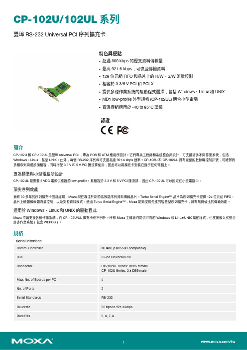
CP-102U/102UL系列雙埠RS-232Universal PCI序列擴充卡特色與優點•超過800kbps的優異資料傳輸量•最高921.6kbps,可快速傳輸資料•128位元組FIFO和晶片上的H/W、S/W流量控制•相容於3.3/5V PCI和PCI-X•提供多種作業系統的驅動程式選擇,包括Windows、Linux和UNIX•MD1low-profile外型規格(CP-102UL)適合小型電腦•寬溫模組適用於-40to85°C環境認證簡介CP-102U和CP-102UL是雙埠universal PCI,專為POS和ATM應用所設計。
它們專為工程師和系統整合商設計,可支援許多不同作業系統,包括Windows、Linux,甚至UNIX。
此外,每個RS-232序列埠可支援高達921.6kbps速率。
CP-102U和CP-102UL具有完整的數據機控制訊號,可確保與多種序列周邊設備相容,同時搭配3.3V和5V PCI匯流排使用,因此可以將擴充卡安裝在幾乎任何電腦上。
專為標準與小型電腦所設計CP-102UL是需要5VDC電源供應器的low-profile。
其相容於3.3V和5V PCI匯流排,因此CP-102UL可以固定在小型電腦中。
頂尖序列效能擁有30多年的序列擴充卡設計經驗,Moxa現在專注於新的高效能序列資料傳輸晶片。
Turbo Serial Engine™晶片為序列擴充卡提供128位元組FIFO、晶片上硬體和軟體流量控制,以及突發資料模式。
透過Turbo Serial Engine™,Moxa能夠提供先進的智慧型序列擴充卡,具有無與倫比的傳輸效能。
適用於Windows、Linux和UNIX的驅動程式Moxa持續支援各種作業系統,而CP-102U/UL擴充卡也不例外。
所有Moxa主機板均提供可靠的Windows和Linux/UNIX驅動程式,也支援嵌入式整合許多作業系統(包含WEPOS)。
映泰A770L3主板 BIOS说明书

免责说明
本手册内容系 BIOSTAR®知识产权,版权归 BIOSTAR®所有。我们本着对用户负 责的态度,精心地编写该手册,但不保证本手册的内容完全准确无误。BIOSTAR® 有权在不知会用户的前提下对产品不断地进行改良、升级及对手册内容进行修正, 实际状况请以产品实物为准。本手册为纯技术文档,无任何暗示及影射第三方之 内容,且不承担排版错误导致的用户理解歧义。本手册中所涉及的第三方注册商 标所有权归其制造商或品牌所有人。
SATA II
板载串行ATA控制器
数据传输率为3 Gb/s 符合SATA 2.5 规范
网络
Realtek RTL 8102EL
10 / 100 Mb/s自适应传输模式 半双工/全双工工作模式
音效
ALC662 / VT1708B
6声道音频输出 支持高清音频
PCI Express Gen2 x16 插槽
注意: 此附件内容可能会因区域或主板版本而异。
1
主板手册
1.3 主板特性
SPEC
CPU
Socket AM3 AMD Sempron / Athlon II / Phenom II处理器 (最大瓦数:95W)
AMD 64架构兼容32和64位 支持Hyper Transport 3.0技术
支持HyperTransport 3.0
amdsb710环境控制ite8721hw监控高级io控制器提供最基本的io功能风扇速度控制器低管脚数接口ites智能保护功能双通道模式ddr3内存模块ddr3dimm插槽x2支持ddr380010661333主内存最大内存容量为8gb支持ddr31600oc每个dimm支持512mb1gb2gb4gbddr3不支持registereddimm和eccdimmmultiworddma多字节dmaide板载ide控制器ultradma3366100133总线控制模式数据传输率为3gbssataii板载串行ata控制器符合sata25规范10100mbs自适应传输模式网络realtekrtl8102el半双工全双工工作模式6声道音频输出音效alc662vt1708b支持高清音频pciexpressgen2x16插槽x1支持pciegen2x16扩展卡插槽pciexpressgen2x1插槽x1支持pciegen2x1扩展卡pci插槽x3支持pci扩展卡软驱接口x1每个接口支持2个软驱打印机接口x1每个接口支持1个打印机端口板载接口ide接口x1每个接口支持2个ide设备sata接口x4每个接口支持1个sata设备2a770l3spec前置面板接口x1支持前置面板设备前置音频接口x1支持前置音频功能spdif输出接口x1支持数字音频输出功能cpu风扇接头x1cpu风扇电源智能风扇功能系统风扇接头x1系统风扇电源清空cmos数据接头x1清空cmos数据usb接口x2每个接口支持2个前置面板usb端口电源接口24pinx1连接电源电源接口4pinx1连接电源ps2键盘x1连接ps2键盘ps2鼠标x1连接ps2鼠标串行端口x1连接rs232端口后置面板接口lan端口x1连接rj45以太网数据线usb端口x4连接usb设备音频插孔x3提供音频输入输出和连接麦克风接口主板尺寸182mmwx305mmlatx特性支持raid0110如有增加或减少任何os支持biostar保留不预先通操作系统支持windowsxpvista7知的权利
PCI6505-开关量输入输出卡
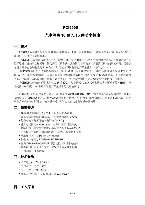
PCI6505光电隔离16路入/16路功率输出一、概述PCI6505板是独立光电隔离16路开关量输入16路开关量功率输出,该板卡简单可靠,输入输出电压范围广,符合PCI总线标准。
PCI6505开关量输入部分采用光电隔离技术,实现16路电压型开关量的并行输入,有效的避免了外部环境对主机的干扰和损坏,输入采用共地方式,各路输入相互独立,只要选用适当的限流电阻,保证光电耦合器件的输入电流为4mA左右,即可适应不同电压的开关量输入,出厂为0~12V。
PCI6505输出部分采用光隔离技术,实现16路开关量独立输出,上电自动清零.可以提供TTL电平输出,也可以提供功率输出,其输出端最大功率可驱动24V/200mA负载或12V/200mA,可直接驱动继电器,电磁阀。
各路输出信号均具有锁存功能。
出厂为功率输出方式。
CPU输出数据为正向驱动。
PCI6505功率输出时要求用户从37芯IDC接头提供+24V或+12V电源给功率驱动芯片(2803)。
电源提供24V还是12V由用户需要开关量输出的电压值而定。
PCI6505采用芯片表贴技术。
出厂时提供Win98/2000/NT/XP下测试程序和动态链接程序(DLL)及编程指导(DEMO程序),有VB/VC采集程序例程,并提供两年的质保服务。
由于是PCI总线,用户不必关心板卡的实际地址,安装板卡时,PCI协议自动分配该板的基地址。
二、性能特点·16路开关量输入,16路TTL电平或功率输出·光电隔离为电流驱动方式,一分钟内可耐压5000V·每个点输入电压可选(出厂为0~12V)·输入电流限制在4mA左右,由R1~R32阻值决定·各输出信号具有锁存功能,驱动能力为+24V/200mA·工作模式为CPU扫描刷新输出,最快扫描周期<5μS·基地址浮动,由PCI协议管理地址·物理I/O地址为BASE+0~BASE+1H·提供WIN/98/2000/NT/XP下驱动程序及动态连接库·功率输出时须从机外提供+12V或+24V辅助电源·工作电流:<350mA三、技术参数·工作电压:5V±0.25V·工作温度:0℃~50℃·湿度:5%~95%·外部工作电压:24V±1.0V或12V±0.5V四、工作原理1.工作原理图(图1)PL DI0 DI15 DO0 DO15图1:逻辑方框图五、使用方法1.端口地址设置 P CI 总线地址为浮动地址,由PCI 总线协议分配,物理地址为BASE+0H ~BASE+1H , 用户在使用PCI 总线数据采集板时不必去关心具体的板卡地址,其地址管理由PCI 协议分配,用户编程时只需调用我公司提供的DLL 库即可,下面说明的板卡地址,只是让用户详细了解本板的功能。
PCI-1730 快速说明书

1.1.2 宽的输入范围
PCI-1730 具有宽的输入范围,适合于很多供电电源 12VDC 和 24VDC 的工 业应用场合。
1.1.3 复位保护满足了工业应用的需求
当系统热重启动(不关闭系统电源)时,PCI-1730 根据卡上的跳线设置, 能够保持每个通道的输出值,或返回到它们打开状态的默认配置。该功能能够避 免在系统意外重启动过程中的误操作对系统带来的危险。
PCI-1730 快速安装使用手册
PCI-1730 快速安装使用手册
PCI-1730 快速安装使用手册 ...................................... 1 第一章 产品介绍 ............................................... 2
2.2 跳线的设置
PCI-1730 卡面板上有 3 个跳线来实现两种功能和 1 个功能开关 SW1。如何 使用它们将在下面详细讨论。
2.2.1 版本设置
跳线 JP4 到 JP5 是用来设置选择板卡版本。设置如下图所示:
3
PCI-1730 快速安装使用手册
2.2.2 设置重启状态 PCI-1730 用跳线 JP2 来选择设置重启后每个数字输出通道保持上一次的数 字输出设置和输出值,或者返回到默认配置。这种特有的功能能使用户选择是在 每次重启后清除原来输出设置和输出值还是保持原有设置和输出值而只有当系 统断电后才清除。卡上输出通道的默认配置是“OFF”配置。在断电后,卡将清 除它的设置和输出值返回默认状态。具体如下图所示:
PCI8002A同步高速数据采集卡硬件操作说明书(doc 32页)(正式版)
PCI8002A 同步高速数据采集卡硬件使用说明书阿尔泰科技发展有限公司产品研发部修订阿尔泰科技发展有限公司目录1PCI8002A 同步高速数据采集卡硬件使用说明书版本:6.1112阿尔泰科技发展有限公司第一章功能概述信息社会的发展,在很大程度上取决于信息与信号处理技术的先进性。
数字信号处理技术的出现改变了信息与信号处理技术的整个面貌,而数据采集作为数字信号处理的必不可少的前期工作在整个数字系统中起到关键性、乃至决定性的作用,其应用已经深入到信号处理的各个领域中。
实时信号处理、数字图像处理等领域对高速度、高精度数据采集卡的需求越来越大。
ISA 总线由于其传输速度的限制而逐渐被淘汰。
我公司推出的基于PCI 总线、USB 总线等数据采集卡综合了国内外众多同类产品的优点,以其使用的便捷、稳定的性能、极高的性价比,获得多家客户的一致好评,是一系列真正具有可比性的产品,也是您理想的选择。
第一节、产品应用本卡是一种基于PCI 总线的数据采集卡,可直接插在IBM-PC/AT 或与之兼容的计算机内的任一PCI 插槽中,构成实验室、产品质量检测中心等各种领域的数据采集、波形分析和处理系统,也可构成工业生产过程监控系统。
它的主要应用场合为:◆电子产品质量检测◆信号采集◆过程控制◆伺服控制第二节、总线及制作工艺特点◆32 位PCI 总线,支持PCI2.2 协议,真正实现即插即用◆支持5V PCI 总线(总线上的+5V 和+12V 均被使用)◆FPGA 接口芯片设计,具有极高的保密性,特别适合OEM 合作第三节、AD模拟量输入功能◆转换器类型:AD9224◆输入量程:±5V、±2.5V、±1V、±0.5V◆转换精度:12 位(Bit)◆采样速率(同步采样)最高采样速率为40MHz(25 纳秒/点)最低采样速率为400KHz(约 2.5 微秒/点)分频公式:采样频率= 主频/ 分频数,其中主频= 80MHz,32 位分频,分频数的取值范围:最低为2,最高为200◆物理通道数:4 通道(各通道完全独立同步采样)◆模拟量输入方式:单端模拟输入◆模拟输入阻抗:>10MΩ◆模拟输入共模电压范围:<±2V◆通道切换方式:4 通道同时转换◆数据读取方式:软件读取方式、DMA 方式(此方式速度最高)◆存诸器深度:每通道512K 字(点)RAM 存储器◆时钟源选项:板内时钟和板外时钟软件可选◆触发模式:软件内部触发和硬件外部触发◆触发类型:边沿触发触发◆触发方向:负向触发、正向触发、负正向触发◆触发电平:共4096 级软件可调,可调范围为±10V1PCI8002A 同步高速数据采集卡硬件使用说明书版本:6.111◆触发灵敏度:软件可选范围为1~65535(819uS)◆模拟量触发源:AI0、AI1、AI2、AI3、ATR、DTR (软件可选)◆系统测量精度:0.1%◆工作温度范围:-40 ~+85℃◆存储温度范围:-40 ~+120℃第四节、DI数字量输入功能◆通道数:8 路◆电气标准:TTL- CMOS 兼容◆最大吸收电流:小于0.5mA(毫安)◆高电平的最低电压:2V◆低电平的最高电压:0.8V第五节、DO数字量输出功能◆通道数:8 路◆电气标准:CMOS 兼容◆最大下拉电流:20mA◆最大上拉电流:2.6mA(毫安)◆高电平的最低电压:3.4V◆低电平的最高电压:0.5V第六节、其他指标◆板载时钟振荡器:80MHz第七节产品安装核对表打开PCI8002A 板卡包装后,你将会发现如下物品:1、PCI8002A 板卡一个2、ART 软件光盘一张,该光盘包括如下内容:a) 本公司所有产品驱动程序,用户可在PCI 目录下找到PCI8002A 驱动程序;b) 用户手册(pdf 格式电子文档);第八节安装指导一、软件安装指导在不同操作系统下安装PCI8002A板卡的方法一致,在本公司提供的光盘中含有安装程序Setup.exe,用户双击此安装程序按界面提示即可完成安装。
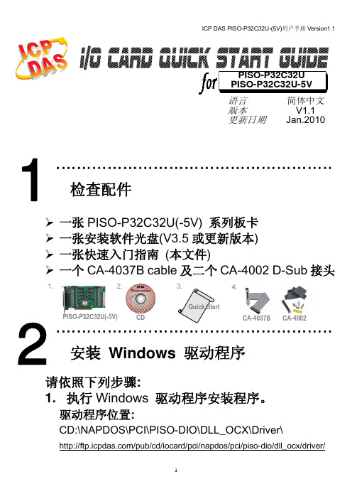
泓格PCI总线数字量输入输出卡PISO-P32C32U快速启动手册
Service@
Copyright ©2010 by ICP DAS Co., Ltd. All rights are reserved
-9-
权利声明和友善提示
承诺
郑重承诺:凡泓格科技股份有限公司产品从购买即日起一年内无任何材料性缺损。
权利声明
泓格公司拥有本手册的所有权利,包括泓格公司的专利、著作权等产权利益。任何团体或个人,未 经泓格公司明确的授权,不得复制、传播或使用本手册全部或其中的内容进行商业活动,违者将要对造 成的任何损失承担责任。
相关软件位置:
CD:\NAPDOS\PCI\PISO-DIO /pub/cd/iocard/pci/napdos/pci/piso-dio/
泓格科技(ICP DAS)主网页
联络方式
专业技术支持 代理商及订购信息 新技术、产品及解决方案的相关信息 常见问题 应用案例
6
ICP DAS PISO-P32C32U-(5V)用户手册 Version1.1
PISO-P32C32U 接线图解:
CON1
CA-3710
CON2
+24 V
GND
GND
外部供电:
+5 V
DP-665
DN-37 I/O 接线
20 21 22 23 24 25 26 27 28 29 30 31 32 33 34 35 36 37
2
DI 1
3
DI 2
4
DI 3
5
DI 4
6
DI 5
7
DI 6
8
DI 7
9
DI 8
10
DI 9
11
DI 10 12
DI 11 13
- 1、下载文档前请自行甄别文档内容的完整性,平台不提供额外的编辑、内容补充、找答案等附加服务。
- 2、"仅部分预览"的文档,不可在线预览部分如存在完整性等问题,可反馈申请退款(可完整预览的文档不适用该条件!)。
- 3、如文档侵犯您的权益,请联系客服反馈,我们会尽快为您处理(人工客服工作时间:9:00-18:30)。
PCI2362数字量输入输出卡硬件使用说明书北京阿尔泰科技发展有限公司产品研发部修订北京阿尔泰科技发展有限公司目录目录 (1)第一章功能概述 (2)第一节、产品应用 (2)第二节、DIO数字量输入/输出功能 (2)第三节、定时/计数器功能 (2)第四节、板卡尺寸 (2)第五节、产品安装核对表 (2)第六节、安装指导 (2)一、软件安装指导 (3)二、硬件安装指导 (3)第二章元件布局图及简要说明 (4)第一节、主要元件布局图 (4)第二节、主要元件功能说明 (4)第三节、信号输入输出连接器定义 (4)一、XS1连接器定义 (4)二、XS2连接器定义 (6)三、XS3连接器定义 (7)第三章各种信号的连接方法 (10)第一节、DI数字量输入的信号连接方法 (10)第二节、DO数字量输出的信号连接方法 (10)第三节、定时计数器信号的连接方法 (11)第四章地址空间的分配 (12)第五章产品的应用注意事项、校准、保修 (16)第一节、注意事项 (16)第二节、保修 (16)第三节、产品组成 (16)PCI2362数字量输入输出卡硬件使用说明书版本:6.16第一章功能概述信息社会的发展,在很大程度上取决于信息与信号处理技术的先进性。
数字信号处理技术的出现改变了信息与信号处理技术的整个面貌,而数据采集作为数字信号处理的必不可少的前期工作在整个数字系统中起到关键性、乃至决定性的作用,其应用已经深入到信号处理的各个领域中。
实时信号处理、数字图像处理等领域对高速度、高精度数据采集卡的需求越来越大。
ISA总线由于其传输速度的限制而逐渐被淘汰。
我公司推出的PCI2362数据采集卡综合了国内外众多同类产品的优点,以其使用的便捷、稳定的性能、极高的性价比,获得多家试用客户的一致好评,是一款真正具有可比性的产品,也是您理想的选择。
第一节、产品应用本卡是一种基于PCI总线的数据采集卡,可直接插在IBM-PC/AT 或与之兼容的计算机内的任一PCI插槽中,构成实验室、产品质量检测中心等各种领域的数据采集、波形分析和处理系统。
也可构成工业生产过程监控系统。
它的主要应用场合为:◆ 电子产品质量检测◆ 信号采集◆ 过程控制◆ 伺服控制第二节、DIO数字量输入/输出功能◆ 通道数:48路双向开关量输入/输出通道,24路开关量输入,24路开关量输出◆ 通过软件控制,该板最大可以配置开关量输入72路,开关量输出72路◆ 电气标准:TTL、DTL兼容◆ 输入输出信号最高切换频率10M(方波)第三节、定时/计数器功能◆ 通道数:3路◆ 软件设置各个通道的CLK时钟来源:内部10M、外部输入或级联使用◆ 软件设置各个通道的GATE门控信号:低电平、高电平、外部同相输入或外部反相输入◆ 8253的OUT输出可以触发中断◆ TTL、DTL电平兼容第四节、板卡尺寸板卡尺寸:176 mm x 98 mm x 15 mm第五节、产品安装核对表打开PCI2362板卡包装后,你将会发现如下物品:1、PCI2362板卡一个2、ART软件光盘一张,该光盘包括如下内容:a)本公司所有产品驱动程序,用户可在PCI目录下找到PCI2362驱动程序;b)用户手册(pdf格式电子文档);第六节、安装指导北京阿尔泰科技发展有限公司一、软件安装指导在不同操作系统下安装PCI2362板卡的方法一致,在本公司提供的光盘中含有安装程序Setup.exe,用户双击此安装程序按界面提示即可完成安装。
二、硬件安装指导在硬件安装前首先关闭系统电源,待板卡固定后开机,开机后系统会自动弹出硬件安装向导,用户可选择系统自动安装或手动安装。
注意:不可带电插拔板卡。
PCI2362数字量输入输出卡硬件使用说明书版本:6.16第二章元件布局图及简要说明第一节、主要元件布局图第二节、主要元件功能说明请参考第一节中的布局图,了解下面各主要元件的大体功能。
XS1:48路双向开关量输入/输出通道插座XS2:24路开关量输出(DO48-DO71)和前8路开关量输入(DI72-DI79)XS3:后16路开关量输入(DI80-DI95)和三组计数器以上连接器的详细说明请参考《信号输入输出连接器定义》章节。
第三节、信号输入输出连接器定义一、XS1连接器定义关于62芯D型插头XS1的管脚定义(图形方式)北京阿尔泰科技发展有限公司关于62芯D 型插头XS1的管脚定义(表格形式)管脚号名称特性管脚号名称特性管脚号名称特性42 DIO1 IN/OUT 21 DIO0 IN/OUT 62 DIO2 IN/OUT 41 DIO4 IN/OUT 20 DIO3 IN/OUT 61 DIO5 IN/OUT 40 DIO7 IN/OUT 19 DIO6 IN/OUT 60 DIO8 IN/OUT 39 DIO10IN/OUT 18 DIO9 IN/OUT 59 DIO11 IN/OUT 38 DIO13IN/OUT 17 DIO12 IN/OUT 58 DIO14 IN/OUT 37 DIO16IN/OUT 16 DIO15 IN/OUT 57 DIO17 IN/OUT 36 DIO19IN/OUT 15 DIO18 IN/OUT 56 DIO20IN/OUT 35 DIO22IN/OUT14 DIO21IN/OUTPCI2362数字量输入输出卡硬件使用说明书版本:6.1655 DIO23IN/OUT 34 DIO25IN/OUT 13 DIO24 IN/OUT 54 DGND GND 33 DGND GND 12 DGND GND 53DGNDGND 32DGNDGND 11DGNDGND52 DIO26IN/OUT 31 DIO28IN/OUT 10 DIO27 IN/OUT 51 DIO29IN/OUT 30 DIO31IN/OUT 9 DIO30 IN/OUT 50 DIO32IN/OUT 29 DGND GND 8 DIO33 IN/OUT 49 DGND GND 28DGNDGND 7 DGND GND48 DIO34IN/OUT 27 DIO36IN/OUT 6 DIO35 IN/OUT 47 DIO37IN/OUT 26 DIO39IN/OUT 5 DIO38 IN/OUT 46 DIO40IN/OUT 25 DIO42IN/OUT 4 DIO41 IN/OUT 45 DIO43IN/OUT 24 DIO45IN/OUT 3 DIO44 IN/OUT 44 DIO46IN/OUT 23 DGND GND 2 DIO47 IN/OUT 43 DGNDGND22 DGNDGND1 DGNDGND管脚信号名称管脚特性管脚功能定义注释 DIO0~DIO47 Input/Output 开关量输入/输出通道DGND GND 数字信号地,当输入输出数字信号时最好用它作为参考地二、XS2连接器定义关于40芯插头XS2的管脚定义(图片形式)北京阿尔泰科技发展有限公司关于40芯插头XS2的管脚定义(表格形式)管脚号管脚名称电气特性管脚号管脚名称电气特性1 DO48 OUT2 DO49 OUT3 DO50 OUT4 DO51 OUT5 DO52 OUT6 DO53 OUT7 DO54 OUT 8 DO55 OUT9 DGND GND 10 DGND GND11 DO56 OUT 12 DO57 OUT13 DO58 OUT 14 DO59 OUT15 DO60 OUT 16 DO61 OUT17 DO62 OUT 18 DO63 OUT19 DGND GND 20 DGND GND21 DO64 OUT 22 DO65 OUT23 DO66 OUT 24 DO67 OUT25 DO68 OUT 26 DO69 OUT27 DO70 OUT 28 DO71 OUT29 DGND GND 30 DGND GND31 DI72 IN 32 DI73 IN33 D74 IN 34 DI75 IN35 DI76 IN 36 DI77 IN37 DI78 IN 38 DI79 IN39 DGND GND 40 DGND GND管脚信号名称管脚特性管脚功能定义注释DO48~DO71 Output 开关量输出通道DI72-DI79 Input 开关量输入通道数字信号地,当输入输出数字信号时最好用它作为参考地DGND GND三、XS3连接器定义关于40芯插头XS3的管脚定义(图片形式)PCI2362数字量输入输出卡硬件使用说明书版本:6.16关于40芯插头XS3的管脚定义(表格形式)管脚号管脚名称电气特性管脚号管脚名称电气特性1 DI80 IN2 DI81 IN3 DI82 IN4 DI83 IN5 DI84 IN6 DI85 IN7 DI86 IN 8 DI87 IN9 DGND GND 10 DGND GND11 DI88 IN 12 D89 IN13 DI90 IN 14 DI91 IN15 DI92 IN 16 DI93 IN17 DI94 IN 18 DI95 IN19 NC NC 20 NC NC21 NC NC22 NC NC23 NC NC24 NC NC25 NC NC26 NC NC27 DGND GND 28 DGND GND29 ECCLK0 IN 30 ECGATE0IN31 ECOUT0 IN 32 DGND GND33 ECCLK1 OUT 34 ECGATE1IN35 ECOUT1 OUT 36 DGND GND北京阿尔泰科技发展有限公司37 ECCLK2 IN 38 ECGATE2IN39 ECOUT2 OUT 40 DGND GND管脚信号名称管脚特性管脚功能定义注释ECLK0~ECLK2 Input 定时/计数器时钟源输入,在板内有内部CLK,频率为10M。
8253定时/计数器的时钟源可以由软件选择,参考地请使用DGNDEGATE0~EGATE2 Input 定时/计数器门控输入,参考地请使用DGND EOUT0~EOUT2 Output 定时/计数器输出,参考地请使用DGND DI80-DI95 Input 开关量输入通道数字信号地,当输入输出数字信号时最好用它作为参考地DGND GND未连接NC注明:关于DI数字量信号的输入连接方法请参考《DI数字量输入的信号连接方法》章节;关于DO数字量信号的输出连接方法请参考《DO数字量输出的信号连接方法》章节;关于定时/计数器信号的输入、输出连接方法请参考《定时计数器信号的连接方法》章节。
第三章各种信号的连接方法第一节、DI数字量输入的信号连接方法现场开关设备现场开关设备第二节、DO数字量输出的信号连接方法现场开关设备现场开关设备第三节、定时计数器信号的连接方法第四章地址空间的分配PCI2362板的I/O地址分配两组连续空间。