MTPG2_脉冲控制器_使用说明书
Pulse MIG R系列说明书
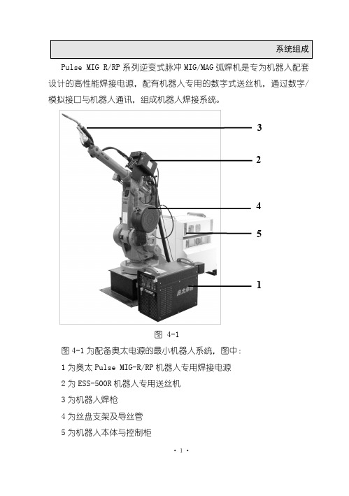
·10·
安川、COMAU 柯马、IGM、新松等一系列进口、国产机器人完成配套(如
图所示)。
二、数字接口控制种类丰富,能直接调用客户存储在焊机的焊接参数,
共可存储 100 套焊接参数。
四、 国际通用标准 Devicenet 数字通讯协议,能与市面上绝大多数的
机器人完成通讯。
五、 预留手动引弧开关, 既可使用机器人焊接,也可进行手动焊接
HS214 E70
100%Ar
100% CO2 82%Ar +18%CO2
四、焊机操作 1、焊机控制面板
焊机的控制面板用于焊机的功能选择和部分参数设定。控制面板包
·12·
括数字显示窗口、调节旋钮、按键、发光二极管指示灯。如图 5-1 所 示。
图 5-1
(1)调节旋钮
调节各参数值。该调节旋钮上方指示灯亮时,可以用此旋钮调节
使用模拟接口需要购买模拟接口控制电缆,使用数字接口需要购买机 器人接口盒。
MIG 焊接方式可实现碳钢富氩、CO2 气体保护焊,P-MIG 焊接方式可 实现碳钢及不锈钢、铝及其合金、铜及其合金等有色金属的焊接。
·9·
二、电源参数
型号 额 定 输 入 电 压 /频 率 额 定 输 入 容 量 ( KVA) 额定输入 电流( A) 额定输出 电压( V) 额定负载 持续率( %) 输出空载 电压( V) 输出电流 范围( A) 输出电压 范围( V)
·5·
坏。当必要时,应该将工件直接与地相接,但在有些国家则不允许直 接接地,只能根据所在国的规定选择适当的电容来实现。
⑹ 屏蔽 对周围设备和其它电缆有选择的进行屏蔽可以减少电磁干扰。对 特殊的应用可以考虑对整个焊接区域进行屏蔽。
·6·
Pundit PL-200PE 商品说明书

®操作说明APundit 触摸屏B 电池C Pundit 脉冲回波传感器*D Pundit 脉冲回波电缆*E Pundit 脉冲回波接触测试板*F 电源G USB 线H DVD 光盘(含软件)I文档*J背带K校准卷尺**“Pundit 脉冲回波传感器”套装中的部件(产品编码 327 40 130)AFJGBHI 物品清单DECK333333333333 3.23Pundit PL-200PE 概述1123456789102目录1. 安全和责任 (5)1.1 通用信息 (5)1.2 责任 (5)1.3 安全说明 (5)1.4 正确使用 (5)2. 技术规格 (6)3. 使用 (7)3.1 入门指南 (7)3.2 主菜单 (8)3.3 设置 (8)3.4 测量屏幕 (10)3.5 测量模式 (11)3.6 用 Pundit PL-200PE 测量 (15)4. 资源管理器 (16)4.1 B-Scan 分析 (16)5. 订购信息 (17)5.1 单位 (17)5.2 传感器 (17)5.3 配件 .............................................176. 保养和支持 .. (18)6.1 保养 (18)6.2 支持理念 (18)6.3 保修信息 (18)6.4 废物处置 (18)7. PL-Link 软件 (18)7.1 启动 PL-Link (18)7.2 查看数据 (19)7.3 调整设置 (20)7.4 B-Scan 分析 (20)7.5 导出数据 (21)7.6 更多功能 (22)1. 安全和责任1.1 通用信息本手册包含了 Pundit PL-200PE 的安全、使用和保养等方面的重要信息。
请在首次使用仪器前仔细阅读本手册。
请安全保管本手册以备将来参考。
1.2 责任我们的“销售和交付一般条款”适用于所有情形。
由于下列某种或多种原因造成的人身伤害或财产损失,我们不予担保,也不承担任何责任:• 未按照本手册所述的使用方法使用该仪器。
脉冲式 GLM 机械隔膜计量泵 安装、操作和维护手册说明书
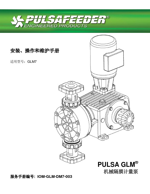
PULSA GLM ®机械隔膜计量泵服务手册编号: IOM-GLM-DM7-003 安装、操作和维护手册适用型号:GLM7Pulsafeeder工厂服务政策如果您的Pulsafeeder泵存在任何问题,请首先查看操作和维护手册中的故障排除指南。
如果该问题在手册中未涉及或者无法解决,请联系您当地的Pulsafeeder授权销售代表,或联系我们的技术服务部,以获取进一步的帮助。
届时将由经过专业培训的技术人员为您诊断故障,并提供解决方案。
解决方案可能包括购买更换部件或将设备返还工厂以供检测和维修。
所有退修品都需具有Pulsafeeder出具的退修品作业和管理号码。
Pulsafeeder技术人员对原部件检查完毕后,将对保修品进行维修所购买的部件费用存入用户名下。
作为故障部件返还的保修部件,如果经测试后运行良好,那么该部件将被送还给发送方,运费由其承担。
电子部件的更换均不接受信用担保。
对于保修范围外的任何维修和改动,需要收取基准费用和更换零部件的相关费用。
安全注意事项:1. 对该设备进行安装或维护之前,请阅读并理解所有相关说明和文件。
2. 请遵守所有特殊说明、备注和注意事项。
3. 在安装、调节和维护过程中,请小心操作并运用良好的常识进行判断。
4. 请确保在设备安装、维护和操作过程中,遵守您所在公司和工厂的所有安全及工作程序和标准。
©2014 Pulsafeeder公司版权所有。
保留所有权利。
本文件信息可能随时更改,恕不另行通知。
未经Pulsafeeder 公司书面授权,除了用于购买方的个人用途以外,严禁对该刊物的任何内容进行复制,严禁在可检索的系统中存放,严禁以任何形式或任何电子或机械途径,包括影印和录音等方式进行传播。
目录1.引言 (4)2.操作原理 (4)2.1 泵头组件 (5)2.2 控制组件 (5)2.3 齿轮减速组件 (5)3.设备检查 (6)4.存储 (6)5.安装 (6)5.1 场地 (6)5.2 管道系统 (7)5.3 入口压力要求 (7)5.4 出口压力要求 (8)6.设备启动 (9)6.1 紧固件检查 (9)6.2 输出调节 (9)6.3 泵头灌注和维护 (10)6.4 泵头灌注 (11)6.5 校准 (13)7.维护 (14)7.1 隔膜拆卸和重新安装 (16)7.2 隔膜轴封 (18)7.3 止回阀 (19)7.4 塑料连接器式止回阀的拆卸与安装 (20)7.5 金属螺栓紧固式止回阀的拆卸与安装 (21)7.6 马达的拆卸与安装 (23)8.备件 (24)8.1 KOPkit方案 (24)8.2 订购KOPkits或备件 (24)8.3 备件包编号: (25)9.编码识别 (25)10. 故障排除 (26)11. 管道附件 (28)12. 外形尺寸图 (29)13. 零件图和零件清单 (31)31. 引言GLM® DM7计量泵是一种容积式、机械操作的往复式隔膜泵。
PRG101 PRG501 2-Stage Pneumatic Regulator说明书

1OPERATIONThe PRG101 and PRG501 regulators employ piston control to achieve their high-gain pneumatic 2-stage servo system. To increase the regulated pressure, the hand wheel is turned clockwise, forcing the measuring capsule/piston assembly downward.This pushes the pilot diaphragm and control diaphragm downward. As a result, the main valve opens and the supply pressure enters the regulator. The resulting pressure change causes the measuring capsule to compress. This compression causes the pilot diaphragm and control diaphragm to move upward, which then shuts the main valve. To decrease the regulated pressure, the hand-wheel is turnedcounterclockwise, forcing the measuring capsule/piston assembly upward. This allows the pilot diaphragm and control diaphragm to move upward. As a result, the relief valve opens and air is exhausted through thevent. The resulting pressure drop causes the measuring capsule to expand. This expansion causes the pilot diaphragm and control diaphragm to move down, which then shuts the relief valve.PRECISION PRESSURE REGULATORSSTANDARD HAND-WHEEL ADJUSTMENTU Two 1⁄4 NPT Gauge Ports StandardU High-Accuracy Regulation U High-Relief Capability U Unaffected by VibrationU Unaffected by Mounting Position U Setpoint Locknut ProvidedThe PRG101 and PRG501 Series pressure regulators have an advanced design consisting of a precision measurement capsule and a high-gain servo amplifier to achieve high performance. The regulator can be used in a “dead end” application and will exhaust whenever the setpoint is lowered. Changes in supply pressure have a minimal effect on regulation accuracy. The regulator can be panel or pipe mounted. The PRG101 has 2 gauge ports available for mounting Omega pressure gauges for local indication. ThePRG501 is ideal for dial gauge readings when the unit is panel mounted. The dial gauge is outside the panel.PRG101 pressure regulator, shown slightly smaller than actual size.PRG101 Series Base UnitsPRG501 Series Base Units with 4" Dia GaugeDimensions: mm (inch)PRG101 SERIES HAND-WHEEL ADJUSTMENT PRG501 SERIES 4" DIAMETER DIAL GAUGE WITH HAND-WHEEL ADJUSTMENTRegulation Accuracy(15 psi Supply PressureChange at Midrange):0.1% (PRG101-25, PRG501-15, PRG501-30)0.05% (PRG101-60, PRG501-60)0.02% (PRG101-120, PRG501-120) Sensitivity: 0.005 psiHysteresis and Repeatability:0.05% of settingOperating Temperature: -20 to 70°C (0 to 160°F)PRG501 Dial Gauge: Dual scale, psi and barResponse Time to 50% Load Change: 0.2 secondsHousing Material: IP65 sealed,zinc diecasting, epoxy painted Diaphragm Material: Nitrile-reinforced elastomersCapsule Material: Beryllium-copperPRG501-120 dial gauge,shown smaller thanactual size.Maintaining a state of equilibrium,the action of the measuring capsuledescribed on the preceding pageensures precise, constant pressureregulation. Air is bled at a constantrate through the bleed orifice so thata very small movement of the pilotvalve induces a substantial pilotpressure change, which creates ahigh servo amplification.PRG501 SeriesSPECIFICATIONSMaximum Supply (Input) Pressure:150 psi (1000 kPa)Minimum Supply (Input) Pressure:3 psi above desired output pressure Minimum Regulated Pressure: 2 psi Media: Dry gases only (oil free), filtered to better than 25 micronsFlow Capacity: 10 SCFM max Consumption @ Midrange:0.01 SCFM (PRG101-25, PRG501-15, PRG501-30)0.02 SCFM (PRG101-60, PRG501-60) 0.04 SCFM (PRG101-120, PRG501-120)Mounting: Any attitude; integralmounting nut suppliedPressure Gauge (PRG501): Phosphorbronze Bourdon tubeProcess Connection:1⁄4 FNPT(pneumatic only)Number of Turns in Control Range:21⁄2 hand-wheel turnsWeight:PRG101: 0.75 kg (1.60 lb)PRG501: 1.15 kg (2.50 lb)2。
GP2数据采集器用户手册说明书
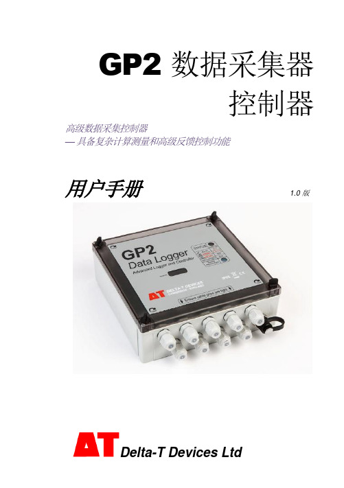
GP2 数据采集器控制器高级数据采集控制器—具备复杂计算测量和高级反馈控制功能用户手册 1.0 版目录目录 (2)开箱 (3)概述 (4)安装 DELTALINK (7)连接至 GP2 (7)帮助信息 (8)6 个步骤轻松创建简单程序 (9)GP2 模拟器 (10)程序示例 (11)检查传感器工作状态和开始记录 (11)取回、查看和保存记录的数据 (11)数据集导入向导 (11)附录 1:GP2 继电器扩展模块 (12)附录 2:GP2 网络布线 (16)附录 3:扩展外壳 (20)附录 4:WS-CAN 外盖 (22)附录 5:DL-MKT 通用数据数据采集器安装套件 (23)附录 6:M-ENCL-B2 机壳 (24)附录 7:确保 GP2 正确密封 (25)GP2 规格 (26)产品保养与维护 (34)GP2 校准证书 (34)法律和法规信息 (34)索引 (35)GP2 包装内容:GP2 数据采集器(带 6AA 电池,需由用户安装)GP2-USB GP2 专用 USB 线缆DVD光盘,内含 DeltaLINK 3 软件、视频教程和文档GP2 用户手册螺丝刀和线缆防水接头扳手可选配件GP2 有 12 个差分模拟输入通道2、四个事件/数字计数器通道和一个 WET 传感器串行输入通道。
使用继电器扩展模块,可将两个输出继电器扩展为 6 个。
两组端子为传感器提供 3V 精密基准电源或非稳压电源。
还有一个 5V 和一个12V 电源端子。
每个传感器可按从 1 秒至 >1000 天的不同频率读取。
任意测量组合可有多种记录频率选择。
提供多种记录类型:平均、最小、最大、总计、累计、风向图、按条件。
数据采集器可保存约 250 万条读数。
每个继电器能控制单独的实验、区域或测试协议,每个都基于不同的阈值设置或逻辑。
使用传感器库和易用的用户界面,您可在 PC 上快速创建简单程序并发送到数据采集器。
还可创建复杂程序脚本,无需学习编程语言或键入任何命令。
开封开流仪表 L-(B)系列 电磁流量计转换器 使用说明书

电磁流量计转换器使用说明书L-(B)系列开封开流仪表有限公司2011年7月目录1.产品功能说明 (1)1.1基本功能 (1)1.2特殊功能 (1)1.3正常工作条件 (1)1.4与传感器连接型式 (2)1.5安装尺寸图 (2)2.转换器基本电路 (3)3.技术性能指标 (4)3.1执行标准 (4)3.2基本参数与性能指标 (4)4.转换器操作 (7)4.1键盘定义与显示 (7)4.2转换器图 (9)4.3转换器接线图 (10)4.4连接电线电缆特性及连接要求 (12)4.5数字量输出及计算 (15)4.6模拟量输出及计算 (17)5.仪表参数设置 (20)5.1L_M AG B三键转换器参数及操作 (20)5.2L_M AG B四键转换器参数及操作 (24)5.3仪表详细参数说明 (29)6.红外手持遥控键盘 (34)7.报警信息 (34)8.故障处理 (35)8.1仪表无显示 (35)8.2励磁报警 (35)8.3空管报警 (35)8.4测量的流量不准确 (36)9.L_MAGB装箱与贮存 (36)9.1L_MAG B装箱 (36)9.2运输和贮存 (36)附录1励磁频率选择(参考) (37)附录2拨码开关说明 (39)附录3L_MAGB系列转换器HART功能说明.........................................错误!未定义书签。
附录4流量系数修改记录功能 (40)附录5带非线性修正功能补充说明 (42)附录6防雷功能说明 (43)L_mag B型电磁流量计转换器使用说明书1.产品功能说明1.1基本功能■低频方波励磁,励磁频率:1/16工频、1/20工频、1/25工频;■高频方波励磁,励磁频率:1/2工频(适用于浆液测量)(选配);■励磁电流可选定为125mA、187.5mA、250mA、500mA;■无需附加电极的空管测量功能,连续测量,定值报警;■流速测量范围:0.1---15米/秒,流速分辨率:0.5毫米/秒;■交流高频开关电源,电压适用范围:85VAC---250VAC;■直流24V开关电源,电压适用范围:20VDC---36VDC;■网络功能:MODBUS、HART、GPRS、PROFIBUS(选配);■中文、英文显示方式,(可定制其它语言);■内部有三个积算器总量,可分别记录:正向总量、反向总量、差值总量。
电动脉冲 G+微型可调频率驱动器操作、维护和零件手册

ElEctRic chain hOiStVaRiabLe FRequency dRiVe suppLementas directed in manual may cause injury.tabLe oF contentsElectromotive Impulse® •G+ Mini Adjustable Frequency Drives .......3Disclaimer of Warranty .......................................................................3General ...............................................................................................3Power Supply and Electrical Connections .........................................3Operating Instructions ........................................................................4Safety Procedures ..........................................................................4–5Wiring Diagrams .............................................................................6–9Parts Diagrams ...........................................................................10–14Programming the Adjustable Frequency Drive ...........................15–17Parameters .................................................................................17–22Specifications ...................................................................................23Speed Control Methods ...................................................................24Factory Settings .........................................................................25–29Warranty . (30)FoReWoRdThis manual contains important information to help you properly install, operate and maintain your hoist for maximum performance, economy and safety.Please study its contents thoroughly before putting your hoist into operation. By practicing correct operating procedures and by carrying out the recommended preventive maintenance suggestions, you will experience long, dependable and safe service. After you have completely familiarized yourself with the contents of this manual, we recommend that you carefully file it for future reference.The information herein is directed to the proper use, care and maintenance of the hoist and does not comprise a handbook on the broad subject of rigging.Rigging can be defined as the process of lifting and moving heavy loads using hoists and other mechanical equipment. Skill acquired through specialized experience and study is essential to safe rigging operations. For rigging information, we recommend consulting a standard textbook on the subject.to 220 volt - 3 phase - 50 hertz, 208-240 volt - 3 phase - 60 hertz, 380-415 volt - 3 phase - 50 hertz or 440-480 volt - 3 phase - 60 hertz power supply. Before connecting the hoist to the power supply, check that the power to be used agrees with that shown on the hoist identification plate. Hoists with drives are not dual voltage.The hoist should be connected to a branch circuit which complies with the requirements of the National Electrical Code and applicablelocal codes.Remember, operation with low voltage can void the CM repair/ replacement policy. When in doubt about any of the electrical requirements, consult a qualified electrician.the button to the intermediate position for second speedoperation and fully depress the button for fast speedoperation. The hoist speed gradually increases to thenext speed point.d. 2 step infinitely variable control. Partially depress the up ordown push button and the speed of the hoist will graduallyincrease to the slow speed point. Fully depress the buttonand the speed of the hoist will gradually increase to fastspeed operation. Slowly release or depress the up or downpush button and the hoist will operate at a speed betweenthe preset speed points.e. 3 step infinitely variable control. Partially depress the up ordown push button and the speed of the hoist will graduallyincrease to the slow speed point. Depress the button tothe intermediate position and the speed of the hoist willgradually increase to the second speed. Fully depressingthe button will cause the hoist to gradually increase to fastspeed. Slowly release or depress the up or down pushbutton and the hoist will operate at a speed between thepreset speed points.SAFETY PROCEDURESRefer to the hoist manual and:When preparing to lift a load, be sure that the attachmentsto the hook are firmly seated in hook saddle. Avoid off centerloading of any kind, especially loading on the point of hook.When lifting, raise the load only enough to clear the floor orsupport and check to be sure that the attachments to thehook and load are firmly seated. Continue lift only after youare assured the load is free of all obstructions.9. On two and three part reeved hoists, check for twists in theload chain. A twist can occur if the lower hook block has been capsized between the strands of chain. Reverse the capsize to remove twist.10. Do not allow the load to bear against the hook latch. The latchV2 AND RRS CONTACTOR PLATE ASSEMBLIES17211415228321975111086121618201311.1.41.1.31.1.21.11.1.41.1.41.1.11.21.1.21.1.51.1.2pRogRamming tHe adJustabLe FRequency dRiVeUSING THE kEYPADAll functions of the drive are accessed using the keypad. The information needed to configure the drive’s application is entered into the drive by using the functional LEDs. This information is stored into the drive’s memory.kEYPAD FUNCTIONSThe keypad has a 5-digit LED display. Both numeric and alpha-numeric data can appear on the display.Indicators and keys on the keypad are described below.note: the StOP key is always active and will cause any run command to come to an immediate stop.IMpulse•G+ MINI structure of paraMetersFrequency Reference SettingSets/Displays the drive operation speed (Hz).Output Frequency MonitorDisplays the output frequency (Hz.) at which the drive is currently operating. This is a monitor only function; the operator cannot change the displayed value by use of the keypad.Output Current MonitorDisplays the level of output current (Amps) that the drive is currently producing. This is a monitor only function; the operator cannot change the displayed value by use of the keypad.Monitor SelectionPressing ENTER allows access to the various Monitor parameters. These are monitor-only functions; the operator cannot change the displayed value. Accessible during run command. See pages 18 thru 21for complete listing of all monitor parameters.*Parameter ProgrammingSelects or reads data using parameter settings. Data is displayed by pressing the ENTER key, and can be changed by pressing the “up arrow” or “down arrow” keys. Any changes can be saved by again pressing the ENTER key. Pressing the ESC key exits the programming mode.Output Voltage MonitorDisplays the level of output voltage to the motor. This is a monitor only function: The operator cannot change the displayed value by use of the keypad.UserAllows for quick access to parameters that can be programmed by operator.*note: all programming parameters are password protected, except those stored in user function..SPEED CONTROL METHODSThe IMPULSE.G+Mini provides 1-step, 2-step or 3-step Multi-Step control methods. For each input that is energized, the drive begins to operate at the corresponding frequency. If 1, 2 or 3-step is desired, then the frequency reference for the 1st, 2nd or 3rd step will be set at the maximum desired speed of operation.eLectRomotiVe systems Limited WaRRantyElectromotive Systems, hereafter referred to as Company, guarantees that the drive has been manufactured by it against any defects of material and/or workmanship for a period of two years from the date of shipment. Company makes NO OTHER WARRANTY, EXPRESSED OR IMPLIED, AS TO THE MERCHANTABILITY OR FITNESS OF THE ITEMS FOR THEIR INTENDED USE OR AS TO THEIR PERFORMANCE. Any statement, description or specification in Company’s literature is for the sole purpose of identification of items sold by the Company and imparts no guarantee, warranty or undertaking by company of any kind. Components and accessories not manufactured by Electromotive Systems are not included in this warranty and are warranted separately by their respective manufacturers.Company’s sole liability shall be to repair at its factory, or replace any item returned to it within two years from date of shipment,which Company finds to contain defective material or workmanship. All items to be repaired or replaced shall be shipped to Company (Note: return authorization by Company is required) within said two year period, freight prepaid, as a condition to repair or replace defective material or workmanship. Company’s herein assumed responsibility does not cover defects resulting from improper installation, maintenance, or improper use. Any corrective maintenance performed by anyone other than the Company during the warranty period shall void the warranty. Company shall not be liable for damages of any kind from any cause whatsoever beyond the price of the defective Company supplied items involved. Company shall not be liable for economic loss, property damage, or other consequential damages or physical injury sustained by the purchaser or by any third party as a result of the use of any Company supplied items or material.Company neither assumes nor authorizes any other person to assume for Company any other liability in connection with the sale or useof items sold by Company.Materials or items may not be returned for credit, without the prior written consent of the Company. Any authorized return of materialsor items shall be subject to a restocking charge equal to 25% of the net invoiced amount ($100 minimum charge for all control products) after Company determines that the material or item is in resalable condition. If upon receipt of the material or items returned, the Company determines that said material or items cannot be resold without alteration or service, the Company reserves the right to reject the returned materials or items and to send the same back to said purchaser at purchaser’s expense.Any claim for errors in shipment or for material or time shortages must be receive by Company within 30 days of shipment and must be accompanied by copies of the bill of lading and packing slip.Refer to hoist manual for CM’s Repair/Replacement policy that applies to the hoist.31P/N: 10001609 (REV AB) 627NHDecember 2014© 2014 Columbus McKinnon Corporation. All Rights Reserved.P/N: 10001609 REV. AB (627NH)12/14 BJB USa: Ph: (800) 888.0985 • (716) 689.5400 • Fax: (716) 689.5644canaDa: Ph: (877) 264.6478 • Fax: (877) 264.6477。
SDI MWD仪器操作手册

SDI MWD 仪器操作手册SDI MUD PULSE MWD OPERATORS MANUAL(内部资料)美国海顿公司US HAYDEN, INC第一章安全操作科学钻井公司提倡:安全第一。
所有操作必须在阅读操作手册后进行。
每一步安全操作步骤在每一章节详尽描述。
第二章井下仪器安装一仪器运输箱检查安全—在打开运输箱时,必须确保有支架支撑,保证箱子不关闭造成事故。
设备检查—检查运输箱是否损坏。
—检查设备是否损坏。
—列一个需要的设备清单。
如果设备不是自己装的,这是十分必须的。
—如果有影响工作的设备,立即和基地联系。
装箱单—装箱单包括仪器各部分。
—见附录B。
二O型圈替换原则—损坏的密封圈必须更换。
—使用过的密封圈尽量更换。
位置/大小—所有使用的密封圈见下表。
取出/安装—取出—取O型圈时必须用专用工具以免密封圈表面受损。
—观察O型圈槽是否变形。
—如果O型圈槽损坏及时向办公室联系。
—保证O型圈槽清洁。
—安装—完成以上工作后用专用工具安装O型圈。
—在O型圈上涂润滑油。
三仪器丝扣类型—泥浆脉冲MWD仪器有两种扣型。
清洁—在运输过程中仪器丝扣必须用护帽保护,以免灰尘、脏物、水进入。
—如果需要清洁,用线刷清洁丝扣。
粘扣—通常是丝扣表面不清洁,没有涂黄油引起的。
—如果上扣不顺,—停下来,不要继续。
—卸扣。
—清洁丝扣。
—观察丝扣。
—保证扣型一致。
—如果没有粘扣。
—给丝扣涂黄油。
—重新连接丝扣。
—如果粘扣,用备用件。
—和基地联系。
四扶正器观察—保证橡胶块没有损伤,所有螺丝固定。
固定—清洁扶正器固定位。
—清洁螺丝孔。
—选择合适的橡胶块。
—在固定螺丝上涂粘结剂222,安装扶正块。
—拧紧。
大小/调整—扶正块必须与钻铤匹配。
—调整环有三种尺寸:2 1/4"、2 13/16"、3 1/2"。
—如果钻铤内径不标准,切割扶正块使其与钻铤匹配。
五电池检查安全—锂电池有可能爆炸。
—阅读附录A。
里面详细说明电池的安全操作方法以及事故发生的处理方法。
PMG-2中文说明书(1)
PMG-2 质子磁力仪和梯度磁力仪操作手册目录1. 介绍2. 技术指标3. 描述3.1 探头与配件3.2 主机3.3 工作原理3.4 操作控制3.5 显示4. 操作4.1 电源供应4.2 开/关机4.3 电池状况检测5. 基本设置5.1 设置当地时间-TIME5.2 调节磁力仪-TUNE5.3 设置背景灯-BACKLIGHT5.4 选择测量模式-MODE5.5 设置自动关机时间-TIME5.6 设置位置-POSITION5.7 返回所存储的数据-MEMORY6. 测量6.1 装机6.2 探头固定6.3 调谐6.4 单点模式测量6.5 梯度模式测量6.6 自动模式测量7. 数据内存7.1 清除和检查数据-Erase7.2 数据存储7.3 显示存储的数据7.4 数据传输到电脑8.补充信息8.1 USB界面8.2 充电器8.3 保养和维修工作8.4 存储和运输8.5 保修8.6 装箱单1 介绍PMG-2质子磁力仪是一种有内置电池的便携式仪器。
它通过测量氢原子核的质子旋进频率来测量地磁场的绝对值。
磁感应强度矢量又称为磁场矢量。
PMG-2磁力仪有三种测量模式来测量地磁场:单点(SINGLE)模式只用一个探头工作,测量探头附近的磁场总量。
探头接到探杆的顶端。
梯度(GRAD)模式使用两个探头工作。
两个探头同时测量探头所在位置的磁场总量,梯度值为两个探头所测的水平或者垂直磁场的差值:由上端探头测得的磁场值减去下端探头测得的磁场值。
梯度测量消除了一部分干扰域的不良影响,弥补了区域场的影响,不依赖于地球磁场的日变。
自动(AUTO)模式使用一个探头,在一段设定好的时间内重复测量。
测量开始时间和测量间隔需提前设置好。
本模式用于测量地磁场的日变化。
测量结果存储于内部存储器中。
数据可以通过系统提供的软件用USB线导入电脑中,该软件将数据保存在外部计算机上的文本文件中。
仪器的供电由一个内置的无磁铅酸可充电电池来完成,它的无磁性可保证测量结果的准确性,设备也提供充电器。
MTPG脉冲发生器(带加减速)使用说明书

MTPG脉冲发生器使用说明书(步进电机控制专用)慨述·外型尺寸 72×72mm·采用单片机微电脑工作·可适配触点开关与各种霍尔、光电、接近开关·为6位数字显示,1位段值,5位脉冲数值·抗干扰能力达到IEC801 3级MTPG系列脉冲发生器广泛应用于印刷、纺织、橡胶、制药及食品包装等行业,对步进电机控制可替代PLC进行简单的工序控制。
该表具有抗干扰、抗振动能力强,性能稳定、工作可靠。
产品说明一.功能MTPG-5E2N两路NPN型晶体管开漏输出OUT1与OUT2输出对应连接步进电机驱动器的CP和DIR端子(有些是CW和CCW)可设定输出走动步数、运动速度和运动方向可设定多段数:0-15段每段步数设定范围0~59999每段脉冲输出频率和方向可设定输出频率范围:6-9999Hz(电机高速时,注意加减速的设置)方向设置:0 无脉冲输出(停顿计时)1 输出脉冲、正向运动2 输出脉冲、反向运动多个输入功能端子K/P端子:与+12V端子连接时,开始运行,断开停止运行;RESET端子:输入信号时,控制器复位到开始段,并从新开始运行;CP1和CP2为多功能端子:可连续循环运行,强制运行下一段等多种功能;二.主要技术参数·供电电源: AC/DC 100-250V ·辅助输出电源:DC12V 200mA ·整机功耗: 小于4W ·外形尺寸: 72×72×95·整机重量: 230g·输出容量:30V/200mA·信号输入阻抗:≥4.7K·使用环境:温度0~60C°相对湿度≤85%·安装方式:卡入式三.操作说明:1.将仪表接通电源后,正常工作。
2.参数设定:由左到右四个按键定义为:“RES”复位键/返回建,“SET”功能键,“▲”加号键,“▼”减号键。
MTD脉冲持续时间变送器说明书

BEFORE USE ....Thank you for choosing M-System. Before use, please check contents of the package you received as outlined below .If you have any problems or questions with the product, please contact M-System’s Sales Office or representatives. ■PACKAGE INCLUDES:Signal conditioner (body + base socket + input resistor) ..(1)The resistor is provided only with current input type. ■MODEL NO.Confirm Model N o. marking on the product to be exactly what you ordered.■INSTRUCTION MANUALThis manual describes necessary points of caution when you use this product, including installation, connection and basic maintenance procedures.POINTS OF CAUTION■POWER INPUT RATING & OPERATIONAL RANGE• Locate the power input rating marked on the product and confirm its operational range as indicated below:85 – 132V AC rating: 85 – 132V , 47 – 66 Hz, approx. 2.5VA 170 – 264V AC rating: 170 – 264V , 47 – 66 Hz, approx. 2.5VA ■GENERAL PRECAUTIONS• Before you remove the unit from its base socket or mount it, turn off the power supply and input signal for safety . ■ENVIRONMENT • Indoor use.• When heavy dust or metal particles are present in the air, install the unit inside proper housing with sufficient ventilation.• Do not install the unit where it is subjected to continuous vibration. Do not subject the unit to physical impact.• Environmental temperature must be within -5 to +55°C (23 to 131°F) with relative humidity within 30 to 90% RH in order to ensure adequate life span and operation. ■WIRING• Do not install cables close to noise sources (relay drive cable, high frequency line, etc.).• Do not bind these cables together with those in which noises are present. Do not install them in the same duct. ■AND ....• The unit is designed to function as soon as power is sup-plied, however, a warm up for 10 minutes is required forsatisfying complete performance described in the data sheet.COMPONENT IDENTIFICATION■HOW TO OPEN THE FRONT COVER:Position your finger on the hook at the top of front coverand pull.INSTALLATIONDetach the yellow clamps located at the top and bottom of the unit for separating the body from the base socket.Shape and size of the base socket are slightly different with various socket types.■DIN RAIL MOUNTINGSet the base socket so that its DIN rail adaptor is at the bot-tom. Position the upper hook at the rear side of base socket on the DIN rail and push in the lower. When removing the socket, push down the DIN rail adaptor utilizing a screwdriver (–) and pull. ■WALL MOUNTINGRefer to ‘EXTERN AL DI-MENSIONS.’TERMINAL CONNECTIONSConnect the unit as in the diagram below or refer to the connection diagram on top of the unit.When an input resistor is provided with the module, attach it together with input wiring to the input screw terminals. ■EXTERNAL DIMENSIONS unit: mm (inch)CLAMP• When mounting, no extra space is needed between units.■CONNECTION DIAGRAM*Input shunt resistor attached for current input.U V■TERMINAL ASSIGNMENTS unit: mm (inch)INPUT RESISTORInput shunt resistor attached for current input.CHECKING1) Terminal wiring: Check that all cables are correctly con-nected according to the connection diagram.2) Power input voltage: Check voltage across the terminal 7 – 8 with a multimeter.3) Input: Check that the input signal is within 0 – 100% of the full-scale.4) Output: Check that normal voltage pulse (Hi level: 24V ± 2V) is measured at output terminal 1 –2 with an os-cilloscope. Also check that the load resistance meets the described specifications.ADJUSTMENT PROCEDUREConnect a signal source to input terminal, connect a pulse counter or an oscilloscope to output terminal.■FRAME DURATION1) Select a coarse range with Preselection Switch (FR SEL).2) Adjust Frame Duration Adj. (FRAME) to obtain the de-sired frame duration.PRESELECTION SWITCH POSITION (FR SEL)ADJUSTABLE RANGEBY POTENTIOMETER (FRAME)0 0.1 to 0.2 seconds1 0.2 to 0.4 seconds2 0.4 to 0.8 seconds3 0.8 to 1.6 seconds4 1.6 to 3.2 seconds5 3.2 to 6.4 seconds6 6.4 to 12.8 seconds712.8 to 25.6 seconds825.6 to 51.2 seconds951.2 to 102.4 seconds■DUTY RATIOThe procedure to adjust output (duty ratio) to 5 to 95% for input 5 to 95% is shown below.1) ZERO: Apply 5% input and adjust output to 5%.2) SPAN: Apply 95% input and adjust output to 95%.3) Check ZERO adjustment again with 5% input.4) When ZERO value is changed, repeat the above proce-dure 1) – 3).MAINTENANCERegular calibration procedure is explained below:■CALIBRATIONWarm up the unit for at least 10 minutes. Apply 5%, 25%, 50%, 75% and 95% input signal. Check that the output sig-nal for the respective input signal remains within accuracy described in the data sheet. When the output is out of toler-ance, recalibrate the unit according to the “ADJUSTMENT PROCEDURE” explained earlier. LIGHTNING SURGE PROTECTIONM-System offers a series of lightning surge protector for protection against induced lightning surges. Please contact M-System to choose appropriate models.。
TBLM脉冲使用说明书

片被紧紧压在喷管上,脉冲阀呈关闭状态。
当先导阀中压缩空气经电磁阀放掉时,(b)室的压缩空气顶开小膜片尔
排空,由于泄放孔面积大于大膜片上节流孔截面积,故(b)室压力由于压缩
空气补充不上而大大降低,使大膜片受(b)室力小(a)室力,大膜片被上
抬,压缩空气经喷吹管至滤袋内,从而达到清洗滤袋的效果。
3.3、脉冲分配控制器结构与工作原理
0.03~0.2 可调
漏风率 %
≤5 脉冲周期 min
0.1~3 可调
丹阳市南阳除尘设备有限公司
南阳除尘 环保之神
TBLM 系列脉冲布筒滤尘器使用说明书
-2-
表1
型号 TBLM-4 TBLM-10 TBLM-18 TBLM-26-I TBLM-39-I TBLM-52-I TBLM-78-I TBLM-104-I TBLM-130-I TBLM-156-I TBLM-168-I
3170~4220
a 2000
3530~4700
c 2400
4230~5640
b 1800
4750~6340
a 2000
5290~7000
c 2400
6350~8470
b 1800
6350~8470
a 2000
7060~9410
c 2400 8460~11280
b 1800 9520~12700
a 2000 10580~14110
丹阳市南阳除尘设备有限公司
南阳除尘 环保之神
TBLM 系列脉冲布筒滤尘器使用说明书
- 10 -
后,接通电子控制器电源,检查步进电机、电磁阀动作是否正确,脉冲周期
和脉冲宽度的调节是否反应正确。
4.4.11、接通全部电源,进行空车试运转,观察压力表压力是否正常(4.9
电脑脉冲控制仪sxc-x8a1型结构参数和使用说明 (1)
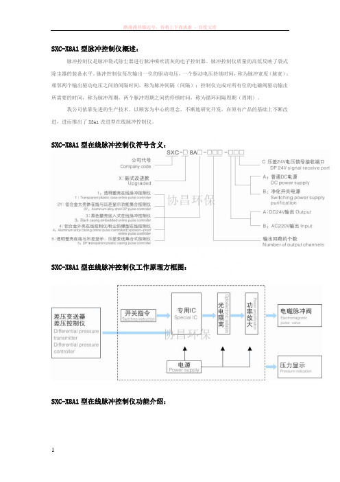
SXC-X8A1型脉冲控制仪概述:脉冲控制仪是脉冲袋式除尘器进行脉冲喷吹清灰的电子控制器。
脉冲控制仪质量的高低反映了袋式除尘器的装备水平。
脉冲控制仪每次输出一位的驱动电压,一个驱动电压持续时间,称为脉冲宽度(脉宽);相邻两个输出驱动电压之间的间隔时间,称为脉冲间隔(间隔);控制仪完成对所有位的电磁阀驱动输出所需要的时间,称为脉冲周期,两个脉冲周期之间的停顿时间,称为循环间隔周期(周期)。
我公司依靠先进的生产技术、以顾客为中心的理念,不断地研究开发,在原有产品的基础上不断改进,进而推出了X8A1改进型在线脉冲控制仪。
SXC-X8A1型在线脉冲控制仪符号含义:SXC-X8A1型在线脉冲控制仪工作原理方框图:SXC-X8A1型在线脉冲控制仪功能介绍:SXC-X8A1-(1-120)型采用挂式透明PC壳,外型美观,防尘性能好,安装方便。
面板上设有数字显示,能依次显示电磁脉冲阀工作顺序,可根据清灰要求,调整脉冲宽度、脉冲间隔和循环间隔周期,控制电磁阀的开启和关闭,对除尘器实行定时清灰。
同时设有压差控制仪输入接点,接上差压控制仪和差压变送器后,可以定差压清灰。
为方便用户自由组合所控制的电磁脉冲阀的个数,采用扩展输出模块,可随意增加或减少控制数量。
脉冲控制仪技术参数和指标:脉冲控制仪额定输入电压AC220V(±10%)50HZ/60HZ脉冲控制仪额定输出电压DC24V/AC220V(或其他订制规格)脉冲控制仪额定输出电流1A脉冲控制仪耗电≤8W脉冲控制仪输出脉冲宽度调节范围0.02-2.55 S脉冲控制仪输出脉冲间隔调节范围1-255 S周期(全部脉冲阀循环一次后到下一循环的时间间隔)1-255 Min脉冲控制仪制电磁脉冲阀的个数1-120脉冲控制仪控制方式定时/定压差脉冲控制仪差压控制输入信号差压显示仪和差压变送器脉冲控制仪使用环境工作温度-20℃~+50℃;空气相对湿度不超过85%;无严重腐蚀气体和导电尘埃;无剧烈震动或冲击;SXC-X8A1型脉冲控制仪具备如下功能:1.脉冲控制仪其中央控制单元采用microchip公司生产的最新PIC单片机,充分发挥了它的物美价廉的软硬件资源,增大了控制功能。
对讲机MTP使用介绍演示文稿

第16页,共37页。
4.1 电池保养——延长电池工作时间
• 要确保对讲机提供最长使用时间,在更换电池时,务必仅 使用摩托罗拉原厂电池。
• 切勿将对讲机和/或电池置于充电器中,除非准备充电。
标准容量电池 - 950 mAh 锂电池 ( FTN6573)
超高容量电池 - 1850 mAh 锂电池(FTN6574)
2.选择更多选项。
3. 选择通话组设置选项。
注意:在TXI模式下,无法启用或停用通话组扫描特性。
第35页,共37页。
3.2 设置通话组扫描
1. 按下菜单键
2. 滚动至更多选项,并选 择。
3. 选择设置通话组 选项。
4. 选择扫描 选项。
5. 选择扫描选项。
6. 如果未启用扫描特性,请选择启 用选项。
借助旋钮选择通话组:
•
在待机屏幕,轻轻按下旋钮并旋转,直至对讲机屏幕显示
需要的通话组。
•
稍等片刻,对讲机屏幕将显示通话组选择选项。
第27页,共37页。
1.4 发起组呼
• 按下并按住PTT键,通话。 松开PTT键,接听。 • 通话组中的成员如果开机,将收到该呼叫。
第28页,共37页。
1.5 接听组呼
安装到位 。
• 不要拎着天线携带对讲机或不停晃动,以免损坏天线 。 • 更换对讲机电池或配件时要先关闭对讲机 • 不要将对讲机当作敲、砸的钝器使用,以免损坏外壳及电路。 • 如遇对讲机使用时发生脱网现象,请先尝试关机后再重新开机。
第22页,共37页。
二. 基本操作
1. 组呼 2. 私密呼叫 3. 扫描 4. 短信 5. 查看本机号码
对讲机MTP使用介绍演示文稿
新款DSP型技GGAJ02微机控制器说明书

概述DSP-I 电除尘高压静电微灵活能把握器是在原DJ-96 型高压静电把握器的根底上升级换代产品,它不仅保存了原产品的先进把握模式承受小液晶显示为客户降低了本钱,而且增加了的把握方式,针对高比电阻粉尘,易产生反电晕的特性,提出了的把握理念,有效的抑制电晕的形式,提高了收尘效果和节约了能源节能可达百分之三十,并且还承受了先进的单片机和液晶汉字显示,在操作性和直观性上更加的简洁易懂。
该把握器有如下特点:1、把握器承受了先进的DSP 和外围芯片,且有功能强、构造简洁、牢靠性高等优点。
2、依据电场中电压电流波形变化的分析,能格外准确性的推断闪络,并作出最正确的处理,闪络处理上实行了下降幅度小,上升速度快,不封锁可控硅的方法,能向电场供给最大的有效电晕功率。
3、供给多种供电运行方式,可满足各种不同工况条件的要求。
4、操作使用便利,设备的开机,停机,参数显示,参数设定,运行方式的变换都可通过操作面板上键盘实现。
5、承受液晶显示屏,可便利地用汉字显示各种参数名称和参数值,使数显示直观、明白。
6、保护功能完善,具有十多种故障保护和报报警功能。
7、具有RS485 通讯接口,可便利地实现远把握,可以接驳DCS 中心集中把握系统。
设备按装拆封1、设备开箱后,应检查设备的部件、附件、备件和技术文件是否齐全。
2、检查把握柜经运输后仪表有无损坏,紧固件有无松动。
3、把握柜内各部件有无松脱现象,觉察特别应准时处理,不能修复的可与公司技术部门联系。
4、检查高压硅整流变压器油箱、油枕及瓷瓶等有无损伤、渗漏油现象。
安装1、把握柜应安装在平坦的平面上,建议装在槽钢上,这样有利于固定,把握柜的外壳又简洁接地。
2、高压硅整流变压器可安装在钢轨或槽钢上,对于安装在户外的高压硅整流变压器建议用户在其上加装简洁的防雨棚构造。
3、按图纸的要求进展接线,留意电源进线和把握柜到变压器之间的连线应按额定电流要求选用适宜截面的导线,二次电压、二次电流取样线、油温取样线应用屏蔽线,连接时应按编号接钱。
GMS-2 操作手册

4.1 首先检查...........................................................................................................................26
4.2 故障处理快速列表...........................................................................................................26
GMS-2 接收机是多功能、多用途的,可用于精密市场。精密市场是指:测量、建筑、 成图、土木工程、精细农业、土方工程和农业机械控制、摄影绘图、水利工程等应用市场。
GMS-2 接收机具有快速、方便的数据采集器所需要的功能、精度、实用性和完整性。
1.1 GMS-2 的主要特点
3.1 GMS-2 可以连接的设备..................................................................................................19
3.2 GMS-2 测量......................................................................................................................22
C.1 GMS-2 技术指标 .............................................................................................................44
脉冲控制仪使用说明

7、控制仪上电后,数码管显示或按键不正常,可能MCU电路损坏,请立即联系我们的售后人员;
八、售后服务
产品整机保修一年,一年后免工时费维修。
接线图:
六、使用说明
1、运行控制(仅支持QYM-ZC-10D、QYM-LC-10D):
2、当线路板上“信号选择”插块连接时,外部运行信号输入无效;
3、当线路板上“信号选择”插块断开时,外部运行信号输入有效。接上电源后,外接的触点没有闭合,控制仪则停止运行,等待外部触点闭合;外部触点闭合后,控制仪开始运行,从第一路开始输出驱动脉冲阀,经脉冲宽度延时,停止输出,再经脉冲间隔延时后,继续输出下一路,至最后一路后,再经周期间隔延时后开始从第一路进行下一个循环周期;
七、常见故障及排除
1、控制仪上电后,电源指示灯不亮,应检查电源输入端子是否松动,电源保险是否熔断,电源变压器是否正常等;
2、控制仪上电后,数码管显示和按键输入正常:
3、输出LED指示灯不亮,电磁阀不动作,可能电路损坏;
4、输出LED指示灯全亮,电磁阀公共端可能接触不良;
5、若某一电磁阀工作不正常,应检查对应的开关管是否漏电或击穿损坏;
该脉冲控制仪产品其操作更直观更简单,性能更稳定。
广泛应用于窑炉,水泥立窑、矿山等行业的除尘清灰系统中。
4、控制仪参数
根据除尘器清灰要求设定脉冲控制仪的脉冲宽度、脉冲间隔、周期间隔、输出路数的参数值使除尘器运行阻力保持在设定范围之内。主要参数如下:
脉冲宽度:控制仪每次输出一路驱动电压,驱动电压持续的时间;
脉冲控制仪上的输出指示二极管依次显示每路驱动电压的输出状态,使控制仪输出状态直观清晰;
数码管显示区显示每个参数运行的计时时间和在参数设定时显示参数设定值;
中特威多功能LCD编程卡 G2 说明书
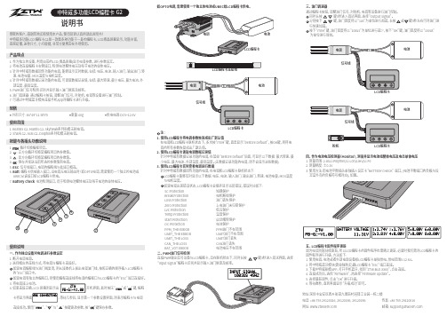
3.将电调接上电池。
4. 如果连接正确,LCD 屏幕则显示出 开机界面,此时按压“ ”或“ ”键,编程卡将显示界面 ,等待几秒后,显示第一个参数设置界面,则表示编程卡与电调 连接成功。
使用“ ”、“ ”与“ ”按键更改参数,按“ ”键保存参数。
说明书产品特点1. 作为独立的设备,利用自带的LCD(液晶屏幕)显示电调参数,进行参数设定。
2. 将电池连接编程卡右侧接口,检测电池整体电压及每节电池的单体电压。
3. 针对中特威有数据回传功能的电调,能够显示实时数据,包括: 电压、电流、输入油门、输出油门、转 速、电池电量、MOS温度与电机温度。
4. 针对中特威有数据记录功能的电调,可读取数据记录值,包括: 最大转速、最小电压、最大电流、外 部温度、最高温度。
5. PWM油门信号检测:识别并显示输入油门脉宽及频率。
6. 油门调速器: 通过编程卡按钮,调整油门信号,对舵机、电调等设备进行油门控制。
7. 可通过中特威蓝牙模块连接手机App对编程卡进行升级。
规格外形尺寸: 84*49*11.5mm 重量:40g 供电电源:DC5~12.6V使用范围1. Beatles G2、Mantis G2、Skyhawk系列航模无刷电调。
2. Shark G2、Seal G2、Dolphin系列船模无刷电调。
1. 断开电调电源。
2. 选择相应的连线方式,将电调与编程卡连接好。
如果电调编程线与油门线复用,则从接收机上拔出电调油门线,按照正确的顺序插入LCD编程卡 的“ESC”插口中。
如果电调有独立的编程口,则使用编程连接线将电调的编程口与LCD编程卡的“ESC”端口连接好。
按键与各插头功能说明使用说明一、 作为独立设备对电调进行参数设定注:1. 使用LCD编程卡将电调参数恢复成出厂默认值 在电调和LCD编程卡联机状态下,多次按“ITEM”键,直至显示“Restore Default”,按OK键,则将电 调的所有参数恢复成出厂默认值。
MMP-II系列微机综合保护装置用户手册

置、变压器、电容器、电感、电抗器、接地符等;各种字体的实时量显示。
● 绘图系统与数据库关联,能方便的进行动态属性的定义。数据连接利用动态颜色、动态
位图使数据的显示变得直观明了,不再是一些死板图形;图元可与实际的设备运行状况
相关联:操作连接使运行人员能直接完成单元提供的各种操作(如遥控遥调、召唤保护
定值等);子图连接使相关图片之间的切换变得直观方便。
二. 运行环境 ● 硬件配置
■ 计算机:选用工业控制计算机 CPU≥PIII1G,内存≥128MRAM,硬盘容量≥40GB, 显 示设备:16K 增强色(推荐:1024╳768 显示分辨率,21’’以上大屏幕)
■ 声卡和音箱:监控主机配备声卡和音箱,用于语音报警提示 ■ 网络器件:包括通讯卡,通讯电缆等 ■ 打印设备:A3 幅面喷墨打印机,用于定时报表打印和随机事故打印 ● 操作系统:简体中文 Windows95/98/ME/NT4.0/2000/XP 三. 主要特征 ● 支持以 RS232/RS422/RS485 等方式组建通讯网络,组网方式灵活简便;
● 支持多种不同厂家的智能电子设备集成于本系统,扩展方便简洁,如智能电度表、小电流
接地选线装置、低压智能断路器、直流屏等;
● 支持包括本公司自定义协议及其他电力系统常用通讯协议,如 IEC60870-5-103 规约、
CDT92 等多种通讯协议;
● 网络运行和数据传输可靠、抗干扰能力强;
● 支持完备的“四遥”功能,即:遥测、遥信、遥控和遥调;
制命令。系统采集的实时数据包括以下:
● 模拟量
模拟量主要包括:有功功率和无功功率、电流、电压、频率、功率因数、零序电压、零序
电流、变压器温度以及其他测量值。
● 状态量
