克罗尼流量计说明书
Coriolis流量计安装说明书

SECTION 40 71 73CORIOLIS MASS FLOW MEASURING SYSTEMPART 1 - GENERAL1.01 SUMMARYA. Coriolis flow meter for permanent installation above ground. The metershall utilize a measuring principle based on the controlled generation of Coriolis forces, whereby both translational and rotational movements are superimposed.The Coriolis flow meter shall produce flow rate, density, temperature andviscosity measurements when specified.B. Related Sections:1. Control and Information System Scope and GeneralRequirements2. Powered Instruments, General1.02 SUBMITTALSA. Furnish complete Product Data, Shop Drawings, Test Reports, OperatingManuals, Record Drawings, Manufacturer’s certifications, Manufacturer’s FieldReportsB. Product Data:1. Dimensional Drawings.2. Materials of Construction:a. Sensing Tube.b. Rated Secondary Containment.c. Process Connection.3. Measurement accuracy.4. Range and range ability.5. Enclosure Rating.6. Classification Rating.7. Power:a. Voltage.b. Wattage.8. Output options.1.03 QUALITY ASSURANCEA. Manufacture instruments in facilities certified to the quality standards ofISO Standard 9001 - Quality Systems - Model for Quality Assurance inDesign/Development, Production, Installation, and Servicing.1.04 DELIVERY, STORAGE, AND HANDLINGA. Store all instruments in a dedicated structure with space conditioning tomeet the recommended storage requirements provided by the Manufacturer.B. Any instruments that are not stored in strict conformance with theManufacturer’s recommendation shall be replaced.1.05 PROJECT OR SITE CONDITIONSA. Provide instruments suitable for the installed site conditions including, butnot limited to, material compatibility, site altitude, process and ambienttemperature, and humidity conditions.1.06 CALIBRATION AND WARRANTYA. The meter shall have standard one year warranty from date of shipment.If the meter is commissioned by a factory certified technician, the warranty is extended to three years from the date of shipment.1.07 MAINTENANCEA. Provide all parts or materials necessary for maintenance and calibrationpurposes throughout the warranty period. Deliver all of these supplies beforeproject substantial completion.1.08 LIFECYCLE MANAGEMENTA. Instrument documentation, like original calibration certificates, manuals and product status information shall be accessible via a web enabled system with a license. The instrument specific information shall be accessed via serial number. When services are provided by an authorized service provider, the service information (ex. subsequent field calibrations) shall be archived and accessible via this web enabled system.PART 2 - PRODUCTS2.01 MANUFACTURERA. One of the following:1. Endress+Hauser - Promass 83A2.02 MANUFACTURED UNITSA. The flow meter shall be a Cajon® 4-VCO-4 or Tri-Clamp® sensor (byapplication and instrument schedule) and transmitter mounted integral (compact) to the sensor.1. The flow meter shall be microprocessor based and possess amethod in which to store the sensor calibration and transmittersetup information in non-volatile memory. The electronics shall beinterchangeable for meters sizes 1/24” – 1/8”.2. The sensor shall be the proper size to measure the design flowrate of the piping and measure bi-directional flow as a standard.3. The sensor shall include a single tube Stainless Steel or Alloy C22material design to promote compatibility, easy installation andmaintenance.4. The system shall simultaneously produce several processvariables (ex. mass flow, volume flow, density, or temperature)while in operation.5. The system shall be a compact design insensitive to externalvibrations and immune from external piping forces due to robustdesign6. The measuring principal shall operate independently of physicalfluid properties such as viscosity and density.B. The transmitter shall be a three-stage microprocessor controller mountedintegrally as specified in the instrument schedule. The transmitter shall operate on a specified AC (85 to 260V) or DC (16 to 62V) power supply. The transmitter housing will carry a NEMA 4X rating and shall be constructed to prevent moisture ingress, promote corrosion resistance, and be impervious to saline environments.1. The transmitter shall allow local or remote programming that canbe operated via an optical display without opening thecompartment.2. The transmitter display shall indicate simultaneous flow rate andtotal flow with 3 Totalizers (ex. forward, reverse and net total) anduser-selectable engineering units, readout of diagnostic errormessages, and support 12 standard languages.3 The transmitter shall safeguard against entering of invalid data forthe particular meter size and all programming parameters shall beaccess-code protected.4. The transmitter output shall be specified, as:4-20mA HART + 10 kHz Pulse Frequency5. The transmitter output(s) shall be integral to the Coriolis flowmetertransmitter electronics; using an external third party signalconverter is unacceptable.6. The transmitter output selected must be supported by Add-onInstructions (AOI), faceplates, device drivers, instructions and pre-engineered code.7. The transmitter shall retain all setup parameters and accumulatedmeasurements internally in non-volatile memory in the event ofpower failure.8. The transmitter shall be protected against voltage spikes from thepower source with internal transient protection.9. The transmitter and sensor must support an NIST traceablemeans of in-situ verification to validate measurement quality overthe lifespan.C. Remote configuration shall be capable of being performed thorough theprogrammable automation controller with common off the shelf tools, software, interfaces or gateways. Generic profiles or special tools and hardware will not be acceptable.2.03 ACCESSORIESA. Stainless steel tag - labeled to match the contract documents.2.04 SOURCE QUALITY CONTROL & CALIBRATIONA. Coriolis flow meters shall be factory calibrated on a gravimetric ISO17025 accredited test stand with certified accuracy traceable to NIST per “General Requirements for the Competence of Testing and Calibration Laboratories”B. Evidence of accreditation must originate from a national verificationagency such as A2LA.C. Each meter shall ship with a certificate of a 2-point calibration reportexceeding stated standard accuracy of 0.1% of rate.D. A real-time computer generated printout of the actual calibration datapoints shall indicate apparent and actual flows. The flow calibration data shall be confirmed by the manufacturer and shipped with the meters to the project site.E. The manufacturer shall provide complete documentation covering thetraceability of all calibration instruments.F. The manufacturer shall provide ISA data sheet ISA-TR20.00.01 as latestrevision of form 20F2321. The manufacturer shall complete the form with all known data and model codes and dash out the inapplicable fields. Incomplete data sheets submitted will result in a rejected submittal.2.05 SAFETYA. All electrical equipment shall meet the requirements of ANSI/NFPA 70,National Electric Code latest addition.B. All devices shall be certified for use in hazardous areas, dependent onthe output protocol selected.C. At a minimum, the device shall allow installation in a Class I, Division 2,Group A to D as a non-incendive design.D. All devices shall be suitable for use as non-incendive devices when usedwith appropriate non-incendive associated equipment.E. Electrical equipment housing shall conform to NEMA 4X classification.F. Non-intrinsically safe electrical equipment shall be approved by aNationally Recognized Testing Laboratory (NRTL) such as CSA, FM, or UL for the specified electrical area classification.PART 3 - EXECUTION3.01 EXAMINATIONA. Examine the complete set of plans, the process fluids, pressures, andtemperatures and furnish instruments that are compatible with installed processcondition.B. Examine the installation location for the instrument and verify that theinstrument will work properly when installed.3.02 INSTALLATIONA. As shown on installation details and mechanical Drawings.B. As recommended by the manufacturer’s installation and operationmanual.C. Specific attention should be given to the following technical requirements:1. Verify flow meter is not installed at the high point of a pipingsystem or directly upstream of a free pipe outlet in a downwardflowing pipe.3.03 FIELD QUALITY CONTROLA. Each instrument shall be tested before commissioning and theENGINEER shall witness the interface capability in the PLC controlsystem and associated registers.1. Each instrument shall provide direct programming capabilitythrough the PLC2. Each instrument shall provide direct control of totalizer resetfunctions through the PLC3. Each instrument shall be supported with a device profile permittingdirect integration in the PLCB. The ENGINEER shall witness all instrument verifications in the field.C. Manufacturers Field Services are available for start-up andcommissioning by a Factory field service representative or amanufacturer’s authorized service provider (ASP) – the warranty againstmanufacturing defects is three years.1. Manufacturer representative shall verify installation of all installedflow tubes and transmitters.2. Manufacturer representative shall notify the ENGINEER in writingof any problems or discrepancies and proposed solutions.3. Manufacturer representative shall perform field verification at thetime of installation for long-term analysis of device linearity,repeatability and electronics health. A comparative report shall begenerated for each meter tested.4. Manufacturer representative shall generate a configuration reportfor each meter.3.04 ADJUSTINGA. Verify factory setup of all instruments in accordance with theManufacturer’s instructions.3.05 PROTECTIONA. All instruments shall be fully protected after installation and beforecommissioning. Replace any instruments damaged before commissioning:1. The ENGINEER shall be the sole party responsible fordetermining the corrective measures。
科隆krohne OPTISWIRL 4200涡街流量计 补充说明

涡街流量计设备保护级别 Gc无火花保护型 ExnA OPTISWIRL 4200补充说明© KROHNE 12/2017 - 4006628801 - AD OPTISWIRL4200 Nepsi ExnA R01 zh内容2 12/2017 - 4006628801 - AD OPTISWIRL4200 Nepsi ExnA1 安全须知31.1 常规注意事项 (3)1.2 NEPSI 证书...............................................................31.3 IECEx 认证. (4)1.4 安全须知.................................................................42 设备描述52.1 仪表说明 (5)2.2 代码描述 (5)2.3 标签 (6)2.4 易燃产品 (8)2.5 设备保护级别(EPL) (8)2.6 保护类型 (9)2.7 环境温度/温度组别 (9)2.8 电气参数................................................................173 安装183.1 安装.. (18)3.2 特殊情况和要求..........................................................194 电气连接204.1 常规注意事项 (20)4.2 电源 (21)4.3 输入/输出..............................................................214.4 接地和等电位连接.. (22)4.5 流量传感器电路(仅适用于分体型)........................................235 操作245.1 启动....................................................................245.2 操作.. (24)5.3 静电放电................................................................246 服务256.1 维护.. (25)6.2 拆卸....................................................................257 笔记2713 12/2017 - 4006628801 - AD OPTISWIRL4200 Nepsi ExnA 1.1 常规注意事项这些附加说明适用于涡街流量计的"nA"无火花型系列防爆产品。
KROHNE电磁流量计产品简介说明书
©KROHNE 03/20027.02425.21.00GRElectromagneticFlowmetersVariable area flowmetersVortex flowmetersFlow controllersElectromagnetic flowmetersUltrasonic flowmetersMass flowmetersLevel measuring instrumentsCommunications technologyEngineering systems & solutionsSwitches,counters,displays and recordersHeat meteringPressure and temperatureApplicationKROHNE electromagnetic flowmeters are to be found in many industrial sectors and applications.Just a small selection:G Chemical industry G Water and wastewaterGHydraulic transport,liquid products with up to 50% solids content G Paper and woodpulp production G Pharmaceutical G Food and beveragesG Filling and dispensing processes G Highly abrasive slurriesG High-pressure industrial processes GPartially filled pipelinesand many,many other applications in other industriesFIT and FORGET !All electromagnetic flowmeters are delivered ready for operation.Install the flowmeter in the pipeline,make the electrical connection,that's it.Always one step ahead with KROHNEThis highly accurate measurement technology is available with integrally or remote mounted converter,some with measuring errors of less than 0.2% of the measured value.The primary head is installed in the pipeline,while the signal converter for signal processing is remote mounted in a field housing or 19" plug-in unit.In the integral system,the signal converter is mounted in a housing with high protection category directly on the primary head.With meter sizes of DN2.5 - 3000 / 1/10" - 120",measurements can be carried out from 2l/h to 300 000m3/hand more.Most of the devices are approved for use in hazardous locations.Various materials are available for the measuring tube,liner and electrodes of the flowmeters for most applications. Electromagnetic flowmetersProduction and calibrationAll electromagnetic flowmeters from KROHNE meet the requirements of CE directives and EMC guidelines.Fabrication and production shops are certified to ISO 9001.At KROHNE,all electromagnetic flowmeters are calibrated by direct comparison of volumes,the most accurate calibration method of all.The KROHNE calibration rigs are the world's biggest and most accurate,and are accredited to EN17 025.Measurement uncertainty is less than 0.013% of themeasured value for meter sizes up to DN 3000 / 120" and above.7Electromagnetic flowmeters >0.05 µS /c m >5 µS /c m >20 µS /c m >50 µS /c mD N 2.5,4,6 1/10”,1/6”,1/4”D N 10 3/8”D N 32 11/2”Signal converterDatenblätterF l a n g e c o n n e c t i o n s F l a n g e l e s s ‘s a n d w i c h ’d e s i g n C h e m i c a l s W a t e r a n d s e w a g e P a r t i a l l y f i l l e d p i p e s P h a r m a c e u t i c a l s ,s a n i t a r y B a t c h i n g (1-10s )V e r y a b r a s i v e s l u r r i e s H i g h p r e s s u r e 2- o r 2 x 2-w i r e s y s t e mG e n e r a l p u r p o s e S a n i t a r y c o n n e c t i o n s H A R T ®/R S 485 (s t a n d a r d )P r o f i b u s P A H A R T ®/R S 485 (o p t i o n )H A R T ® (o p t i o n )O t h e r s o n r e q u e s t m Ao u t p u t ,2 w i r e c o n n e c t i o n ≤3 W ≤5 V A / ≤4.5 W ≤10 V A / ≤8 W ≤15 V A / ≤15 W ≤50 V A 2o r 2 x 2-w i r e s y s t e m 24,48,100 – 240 V A C ,48– 63 H z 24 V D C 24 V A C / D C 100 – 230 V A C ,48 –63 H z L i q u i d s ,p a s t e s S l u d g e a n d s l u r r i e s % s o l i d s /v o l u m e ≤3%S l u d g e a n d s l u r r i e s % s o l i d s /v o l u m e ≤5%S l u d g e a n d s l u r r i e s % s o l i d s /v o l u m e ≤30%P u l s a t i n g f l o w ,< 200 p u l s e s /m i n B a t c h i n g p r o c e s s > 1.5 s P a p e r a n d p u l p H y d r a u l i c t r a n s p o r t (o r e d r e s s i n g )o n l y I F C 090 K -C A P C a p a c i t i v e s i g n a l p i c k u p F ou n d a t i o n F i e l d B u s F A D N 251”D N 40 11/2”D N 502”D N 803”D N 1004”D N 1255”D N 1506”D N 2008”D N 25010”D N 30012”≤D N 1800≤72”≤D N 3000≤120”I S O f i t t i n g l e n g t h o n l y I F C 110 P F a n d I F C 210 E -P F P a r t i a l l y f i l l e d p i p e s ,AQUAFLUXECOFLUX 1000ALTOFLUX 2000ALTOFLUX 4000PROFIFLUX 5000VARIFLUX 6000ALTOFLUX 2W 2 wireBATCHFLUXCAPAFLUXTIDALFLUX partially filledALTOFLUX IFS 2005 FALTOFLUX IFS 4005 FALTOFLUX M 900IFC 010 K,FIFC 020 K,F ,EIFC 040 K 2 wireIFC 090 K,F IFC 090 K-CAP IFC 110 F IFC 110 PFIFC 210 E IFC 210 E-PFSC 150 FBatchflux IFC 012 KElectrical conductivitySizesConnectionsApplications (examples)Flow measurements (examples)Power supply Power consuptionInterfacesIFM 1080 KG Flangeless versionG Rugged measuring tube withstainless steel reinforced 080 KG Flanged connectionsG Steel housingµP-signal converter in plasticsIFM 4080 KG Flanged connectionsG Steel housingTeflon® PFA liner,reinforced withIFM 5080 KG Flangeless versionG Stainless steel housing The only precision flowmeter IFM 6080 KG Various sanitary/flangedconnectionsStainless steel housingG Precision flowmeterG With capacitive signal pickup(electrodes not in contact withG Flangeless versionG Rugged measuring tube withstainless steel reinforced G Flanged connectionsG Steel housingG Liner of Polypropylene,NSF-G Flanged connectionsG Steel housingG Teflon® PFA liner,reinforced withG Flangeless (sandwich) designG Stainless steel housingG The only precision flowmeter with G Flanged connectionsG Steel housingG Measuring tube made of Al2O3G Various sanitary/flanged connec-tions,stainless steel housingG FDA approved Teflon® PFA liner,G Designed for partially filled pipelinesG Excellent measuring accuracy,for low levels,through the integratedG IFC 010 K/IFC 020 K of integral design G IFC 010 F/IFC 020 F in field housing G IFC 020 E 19”plug-in version.G IFC 090 K of integral designG IFC 090 F in field housingG Signal processing by microprocessor,G Signal converter in field housingG Signal processing by microprocessor,outstanding interference rejection,G Signal converter in field housing for wall mounting G Signal processing by microprocessor,outstanding interference rejection,T o w e r h e i g h t 43 m e q u i v a l e n t t o 141 f t / n e t v o l u m e 350000 l i t r e s e q u i v a l e n t t o 95000 U S G a lPrecisionLM28 precision level switches control the flow volume and various computer-aided volume totalizersQmInlet run ≥10 ×DN (DN = meter size)©G The world’s largest and most accurate calibration rigGCalibration of flowmeters up to DN 3000 / 120”GCalibration by direct comparison of volumes,altogether the most accurate method GComparison measurements with so-called master meters are much less accurate and cannot be verifiedGThe volume measurement standards ofKROHNE calibration rigs have been calibrated by NMI,the Netherlands Standards Institute.Measurement uncertainty is less than 0.013% of the measured value.GKROHNE Altometer calibration rigs are accredited in conformity with EN 17 025.GCalibration accuracy is better than 99.97% of the measured value.GThe error of measurement of the calibration rigs is better by a factor of 10 than theaccuracy data of the flowmeter being tested.GAll flowmeters are calibrated underreference conditions,similar to EN 29 104.GAll calibration data are genuine and verifiable; documented in writing in the calibration reports,which are supplied together with each KROHNE flowmeter.An example is shown on the right.E r r o r o f m e a s u r e m e n t [% o f m e a s u r e d v a l u e ]Flow rate [m 3/h]0,50,402000400060008000100000,30,20,10,0-0,1-0,2-0,3-0,4-0,5+ 0.03%Accuracy inspires confidenceAt this flowrate,a typical public swimming-pool can be filled in less than 1 minute.Inaccuracy is less than 0.013% in terms of volume and less than 0.26 mm in terms of filling level (equal to the thickness of a single hair),based on an average pool depth of 2 metres.Flowmeters up to DN 3000/120”creates theKROHNE standardOutlet run ≥2 ×DN (DN =meter size)Volume flow rate Q max = 40 000 m 3/h= 11 m 3/sMeasuring Principle 3.1The induced voltage signal is picked up either by two measuring elec-trodes in conductive contact with the medium or indirectly bycapacitive coupling.A signal converter amplifies the signal and convertsit into a standard analog signal (e.g.4 to 20 mA) and a frequencysignal (e.g.1 pulse for every US gallon or cubic metre of mediumflowing through the measuring tube).To ensure that the voltage is not short-circuited by the pipe wall,themeasuring tube is made of an electrically insulating material or fittedwith an insulating liner.Measurement is largely independent of the flow profile and other prop-erties of the medium,such as pressure,temperature,viscosity,density,consistency,electrical conductivity,and electrode contamination.Measuring systemsThe electromagnetic flowmeter consists of a primary head,that isinstalled in the pipeline,and a signal converter.The compact design has the signal converter mounted directly on theprimary head.For systems with pulsed d.c.field the primary head field coils whichgenerate the magnetic field are energized by a pulsed direct currentfrom the signal converter.The measuring signal is a squarewave voltage of the same frequency.These systems feature extremely small measuring errors. Electromagnetic flowmeters measure the volume flow of electricallyconductive liquids and slurries.Measuring principleAn electric conductor,in this case the electrically conductive medium,passes through a magnetic field.The voltage U induced in this mediumis directly proportional to the mean flow velocity v.Magnetic inductionB (magnetic field strength) and the distance between electrodes D(nominal pipe diameter) are constant.K instrument constantB magnetic field strengthv mean flow velocityD electrode spacingThe volumetric flow rate qv can be calculated according toTherefore:q v=U x D xπ(4)K x B4The reducing angle (α) should not exceed 8°(equivalent to α/2 = 4°),otherwise measuring accuracy may be affected.If the reducing angle is greater,a straight inlet section must be fitted between reducing socket and primary head.Expanding sectionPressure Loss CalculationFor the expanding section,the optimum angle of expansion is α= 8°.ζat α= 8°d1/d2 1.2 1.3 1.4 1.5 1.6 1.7 1.8 1.9 2.0ζ10.0180.0230.02550.0280.030.03080.03150.03230.0332Recommendations for installationSelection of meter sizeThe size of primary head should if possible be selected to provide a velocity of 2 to 3m/s or 6 to 9ft/sec.for the full-scale range. Minimum full-scale range is 0.5m/s or 1.5ft/sec.,maximum is 10 or 11m/s or 30 or 33ft/sec.,depending on flowmeter type.For fluids with a solids content,the velocity should be between 3 and 5m/s or 9 and 15ft/s to prevent deposits and minimize abrasion.Exact determination of flow velocityFor range setting purposes,the exact flow velocity can be determined using the flow table for each nominal pipe width.Example: v in m/sNominal pipe diameter DN150Desired measuring range200m3/hFrom the table we obtain for the flow velocity of 1m/sa flow rate of 63.617m3/h at DN150; for 200m3/hthe flow velocity v is:Example: v in ft/sNominal pipe diameter6”Desired measuring range1000 US GPMFrom the table we obtain for the flow velocity of 1ft/sa flow rate of 88.128 US GPM at 6”meter size;for 1000 US GPM the flow velocity v is:Flow tablesv = 1m/sMeter size Flow rate Meter size Flow rate DN mm m3/h DN mm m3/h2.50.017671250176.71 40.0452********.47 60.10179350346.36 100.28274400452.39 150.63617500706.86 20 1.131********.9 25 1.76717001385.4 32 2.89538001809.6 40 4.52399002209.2 507.068610002827.4 6511.94612004071.5 8018.09614005541.8 10028.27416007238.2 12544.17918009160.9 15063.617200011310 200113.10v = 1ft/sMeter size Flow rate Meter size Flow rate inch US GMP inch US GMP1/100.024********.801/80.03825012352.511/40.1530014479.813/80.3442516626.69 1/20.6120020979.21 3/4 1.3770241410.1 1 2.4480281919.211/4 3.8250322506.8 11/2 5.5080363172.6 29.7921403916.8 21/215.300485640.2 322.032567677.0 439.1686410027 561.2007212691 688.1288015667 8156.67Protection classes to IEC 529/EN 60529。
克罗尼优流2100C流量计与Cub5 Cab显示器指南说明书

Instruction Book for Krohne Optiflux 2100C&Cub 5 Cab DisplayOPERATORS MANUALPLEASE READ THIS MANUAL THOROUGHLY BEFORE OPERATING YOUR NEW FLOW METERGENERAL INFORMATIONREMOTE TRACTOR READOUTThe Red Lion requires no programming or setting up and only has the two control buttons as detailedReading and resetting the Internal Meter in the Krohne Flowmeter.Reading the Total:Depress the down arrow V3 times and read off the middle line which will give the total in M³ (Cubic Metres).Depress the down arrow again to return to the basic screen.Resetting the Total:Press and hold >for 2.5 seconds, then release.The meter will then be displaying ‘quick set up’ then >to language,V to tagV to reset> reset errorsV counter 1> reset counterV yesDepress back arrow to counter 1V counter 2> reset counterV yesDepress back arrow to counter 2Depress back arrow 3 more times to get back to basic screen.Check that counters have been reset by repeating the first operation, i.e. depressing V 3 times and once again to return to basic screen.Metric/Imperial Conversion TableGallons/Litres /Cubic Metres1000 gallons = 4,546 litres = 4.546 m³ 2000 gallons = 9,092 litres = 9.092 m³ 3000 gallons = 13,638 litres = 13.638 m³ 4000 gallons = 18,184 litres = 18.184 m³ 5000 gallons = 22,730 litres = 22.730 m³ 6000 gallons = 27,276 litres = 27.276 m³ 7000 gallons = 31,822 litres = 31.822 m³ 8000 gallons = 36,368 litres = 36.368 m³ 9000 gallons = 40,914 litres = 40.914 m³ 10000 gallons = 45,460 litres = 45.460 m³ 11000 gallons = 50,006 litres = 50.006 m³ 12000 gallons = 54,552 litres = 54.552 m³ 13000 gallons = 59,098 litres = 59.098 m³ 14000 gallons = 63,644 litres = 63.644 m³ 15000 gallons = 68,190 litres = 68.190 m³ 16000 gallons = 72,736 litres = 72.736 m³ 17000 gallons = 77,282 litres = 77.282 m³ 18000 gallons = 81,828 litres = 81.828 m³ 19000 gallons = 86,374 litres = 86.374 m³ 20000 gallons = 90,920 litres = 90.920 m³ 21000 gallons = 95,466 litres = 95.466 m³ 22000 gallons = 100,012 litres = 100.012 m³ 23000 gallons = 104,558 litres = 104.558 m³ 24000 gallons = 109,104 litres = 109.104 m³ 25000 gallons = 113,650 litres = 113.650 m³ Acres/Hectares1 acre = 0.4046856 hectares2 acres = 0.8093712 hectares3 acres = 1.2140568 hectares4 acres = 1.6187424 hectares5 acres = 2.0234280 hectares6 acres = 2.4281136 hectares7 acres = 2.8327992 hectares8 acres = 3.2374848 hectares9 acres = 3.6421704 hectares10 acres = 4.0468560 hectares……………………………1 hectare = 2.471 acres2 hectares = 4.942 acres3 hectares = 7.413 acres4 hectares = 9.884 acres5 hectares = 12.355 acres6 hectares = 14.826 acres7 hectares = 17.297 acres8 hectares = 19.768 acres9 hectares = 22.239 acres10 hectares = 24.710 acres……………………………。
指针金属浮子流量计使用说明书

指针金属浮子流量计使用说明书指针型金属浮子流量计是微小流量金属管浮子式流量测量仪表,该仪表接受变面积式测量原理,测量部件由一个锥形测量管和浮子构成的流量计。
LZZW:现场指示型,可选装一个或二个本安防爆型报警开关(需配备关联设备);LZDW:电远传型,输出4~20mA电流信号(兼容HART通讯协议),同时接受LED光柱现场指示流量。
一、指针型金属浮子流量计特点第三代金属管浮子流量计进一步提高了金属管浮子流量计的可用性和优势性,是引进国外先进计算系统,协同优秀技术研发生产的克罗尼结构金属管浮子流量计,一次成型内外锥管一体式,坚固简洁测量管无死角,浮子可转动不易堵塞,磁性元件不受地磁场影响,低压力损失设计,模块化、智能化、卡件式指示器,相比传统的流量计,具有精度高、重复性好、服务量小等优势,由一个测量管和一个就地指示器构成,无死角测量,低压损失。
适用于各行业的气体和液体测量,测量部分可接受不同的材质来适应不同的介质条件;即使是恶劣环境和腐蚀严重的介质,也具有良好的抗热性和耐压性,指示器还可以选择安装附加的电气部件,指示器接受新型磁耦合结构设计确保传输信号更加稳定。
依据用户要求可以加装磁过滤器,智能型双行液晶显示,可选现场瞬时/累计流量显示,可带背光。
可选二线制、电池、交流供电方式,引进国外先进计算软件保证计算精准明确,并带有数据恢复、数据备份及掉电保护功能。
二、使用注意事项1、仪表安装方向绝大部门浮子流量计必需垂直安装在无振动的管道上,不应有显著的倾斜,流体自下而上流过仪表。
浮子流量计中央线与铅垂线间夹角一般不超过5度,高精度(1.5级以上)仪表θ≤20°。
假如θ=12°则会产生1%附加误差。
仪表无严格上游直管段长度要求,但也有制造厂要求(2—5)D长度的,实际上必要性不大。
2、用于污脏流体的安装应在仪表上游装过滤器。
带有磁性耦合的金属管浮子流量计用于可能含磁铁性杂质流体时,应在仪表前装磁过滤器。
Omega FMC-5000 系列液体流量计说明书

Quick StartShop online at SME-mail: **************For latest product manuals:FMC-5000 Series Coriolis Mass FlowmetersMQS-5773/1016 **************Servicing North America:U.S.A. Omega Engineering, Inc.Headquarters: Toll-Free: 1-800-826-6342(USA & Canada o n l y)Customer Service: 1-800-622-2378(USA &Canada only)Engineering Service: 1-800-872-9436(USA & Canada only)Tel: (203) 359-1660Fax: (203) 359-7700E-mail: **************For Other Locations Visit/worldwideThe information contained in this document is believed to be correct, but OMEGA accepts no liability for any errors it contains, and reserves the right to alter specifications without notice.Step 1: Installation1.1 Basic requirement:The FMC-5000 Series Coriolis Flowmeters should be installed in the orientation that can ensure the measuring tube is filled.For the horizontal installation, the measuring tube should be installed under the pipeline when the process medium is liquid or slurry (shown on Drawing 9) and above the pipeline when the process medium is gas (shown on Drawing 10). For the vertical installation, the measuring tube could be installed besides the pipeline when the process medium is liquid or slurry or gas (shown on Drawing 11)Drawing 9 Drawing 10 Drawing 11 (For Liquid or Slurry) (For Gas) (For liquid or slurry or gas)1.2 Flow direction:There is flow direction arrow that indicates the proper flow direction on the front of the sensor, so please install the FMC-5000 Series Coriolis Flowmeters accordingly. For vertical installation, if the process medium is liquid or slurry, the flow direction should be from down-to-up; if the process medium is gas, the flow direction can be either down-to-up or up-to-down. The transmitter can be mounted with 90° revolutions according to the requirement of installation.*It is better to support the sensor of FMC-5000 Series Flowmeter by rubber connector as the buffer.Step 2: WiringCUT OFF POWER BEFORE CONNECTING CABLESThe power voltage must match that indicated in the junction box of the transmitter and the ground wire must be well grounding to ensure its intrinsic safety performance.2.1 GroundingBoth sensor and the transmitter must be grounded correctly, otherwise a measurement error will occur and the FMC-5000 Series Coriolis Flowmeters may not work. If the pipeline is grounded, the transmitter can be grounded through the pipeline; if the pipeline is not grounded, the transmitter should be grounded independently.2.2 Power line wiringThe transmitter can be supplied with AC220V (-AC Option) or DC24V(Standard). The power line more than 0.8mm2 is recommended and the maximum length of power line should be 300m. For transmitters of FMC-5000 Series Coriolis Meter 6” and larger, a single Driver amplifier is required to be supplied with extra power (AC or DC, depends on transmitter).*The power cable should choose 2-core cable and the area of each core >0.8 square millimeter. *The maximum length of the power cable is 300m.AC Power Wiring (-AC Option) DC Power Wiring (Standard)2.3 RS485 Output WiringRS485 output is compatible to RTU mode of MODBUS protocol. The maximum length of output line is ≤300m.2.4 Configuration ParameterPlease use the operation panel of transmitter to set the configuration, such as basic configuration parameters, zero calibration, cutoff value of low flow and output range of current frequency, etc.(Note: Default Password: “000000”)Step 3: CalibrationGenerally, the FMC-5000 Series Coriolis Flowmeter does not need field calibration because it has been calibrated before delivery.Each FMC-5000 Series Coriolis Flowmeter has its own instrumental coefficient, including one flow coefficient and four density coefficients (high density D1, high period K1, low density D2 and low period K2), which will be shown in Nameplate of Sensor or Calibration certificate.3.1 Zero CalibrationAfter installation, the FMC-5000 Series Coriolis Flowmeter should be powered at least 30 minutes for warm-up and then make the liquid pass through the flow meter until the temperature of FMC-5000 Series Coriolis Meter is same as working temperature of liquid. Afterward, close the downstream valve, make sure the liquid in the flow meter remains at normal temperature, density and pressure and then close the upstream valve to assure the sensor is full of liquid during the process of zero calibration.Finally,Input password to start zero calibration.Notice: Each zero calibration lasts 30s and must repeat at least 10 times.Then all installation and configuration is done.Thanks for choosing FMC-5000 Serious Mass Flowmeter For more information, please visit 。
克罗韦尔 ControlLogix可配置的流量计模块 说明书

ControlLogix 可配置的流量计模块产品目录号为 1756-CFM2罗克⻙尔⾃动化出版物 1756-UM010D-ZH-P - 2021 年9 月ControlLogix 可配置的流量计模块 ⽤⼾⼿册⽤⼾重要须知在安装、配置、操作或维护本产品之前,请阅读本文档以及“其他资源”章节所列的文档,了解关于安装、配置和操作该设备的信息。
除了所有适用的条例、法律和标准的要求之外,用⼾还必须熟悉安装和接线说明。
包括安装、调整、投⼊运⾏、使用、装配、拆卸和维护等在内操作必须由经过适当培训的人员根据适用的操作守则来执⾏。
如果未遵照制造商所指定的方式使用该设备,将可能导致该设备提供的保护失效。
在任何情况下,对于因使用或操作该设备造成的任何间接或连带损失,罗克⻙尔⾃动化公司概不负责。
本手册中包含的示例和图表仅用于说明。
由于任何具体安装都涉及众多变数和要求,罗克⻙尔⾃动化公司对于依据这些示例和图表所进⾏的实际应用不承担任何责任和义务。
对于因使用本手册中所述信息、电路、设备或软件而引起的专利问题,罗克⻙尔⾃动化公司不承担任何责任。
未经罗克⻙尔⾃动化公司的书⾯许可,不得复制本手册的全部或部分内容。
在整本手册中,我们在必要的地方使用了以下注释,来提醒您留意安全注意事项。
设备表⾯或内部还可能贴有以下标签,而标签上给出了具体的预防措施。
本文档的文本中可能会出现下⾯的图标。
警告:标识在危险环境下可能导致爆炸,进而导致人员伤亡、物品损坏或经济损失的操作或情况。
注意:标识可能导致人员伤亡、物品损坏或经济损失的操作或情况。
注意符号可帮助您确定危险情况,避免发生危险,并了解可能的后果。
重要信息标识对成功应⽤和了解本产品有重要作⽤的信息。
电击危险:位于设备(例如,驱动器或电机)表面或内部的标签,提醒相关人员可能存在危险电压。
灼伤危险:位于设备(例如,驱动器或电机)表面或内部的标签,提醒相关人员表面可能存在高温危险。
弧闪危险: 位于设备(例如,电机控制中心)表面或内部的标签,提醒相关人员可能出现弧闪。
P600使用手册完整版

操作程序/主菜单
按ON/OFF键开机,屏幕显示如下:
即:
主菜单
按SCROLL上下来移动光标,选择合适的选项,按ENTER键进入。
主菜单年-月-日时:分:秒
快速启动
查看/编辑设定数据
选择传感器组
数据储存
设置RS232接口
按正确的键可以改变流量的单位。按附加的键可改变读数的时间范围-hr/min/sec(小时/分钟/秒)。
Mains supply:充电器接口RS232:RS232接口Display:显示
4-20mA&pulse:4-20mA和脉冲输出接口Sensor cables:传感器电缆
Red cable indicates +ve flow if upstream:当有回流时,红的接正向
1加仑=4.546升,1美制加仑=3.785升
仪器用米或英尺每秒显示流速。
在流量模式时,会显示累积总流量(正或负),最多12位数字。
Fast Track Set up Procedure快速启动模式
标准的P600流量计放置在一个如下图所示的携带箱中。传感器组A和B是标准配置,但传感器组C是额外的选件。还有传感器组D可选,但会放置在另外一个便携箱中。
管道外径
输入数据
按ENTER键
(详情见后文)
PIPE THICKNESS
管壁厚度
输入数据
按ENTER键
(详情见后文)
PIPE LINING THICKNESS
管道内衬厚度
输入数据
无内衬按ENTER键
(详情见后文)
PIPE WALL MATERIAL
6000型号 Coriolis 流量计 jam 100型 choosing 指南说明书

Section: 14Page: 1Effective Date: October 1, 2021VersaFlow Coriolis 6000Model Selection GuideCM77 Size 100 Stainless Steel or Duplex UNS S31803with Price DataModel Selection GuideHoneywell Proprietary36-CM-16-45Issue 7TABLE II 316 / 316 L Dual certified Stainless Steel UNS S31803 Duplex StandardDN 80 PN 16 to DIN 2501(Tube material SS316 / 316L dual certified only)DN 80 PN 40 to DIN 2501(Tube material SS316 / 316L dual certified only)DN 80 PN 63 to DIN 2501(Tube material SS316 / 316L dual certified only)DN 80 PN 100 to DIN 2501(Tube material SS316 / 316L dual certified only)DN 80 PN 160 to DIN 2501(Tube material UNS S31803 Duplex only)DN 100 PN 16 to DIN 2501(Tube material SS316 / 316L dual certified only)DN 100 PN 40 to DIN 2501(Tube material SS316 / 316L dual certified only)DN 100 PN 63 to DIN 2501(Tube material SS316 / 316L dual certified only)DN 100 PN 100 to DIN 2501(Tube material SS316 / 316L dual certified only)DN 100 PN 160 to DIN 2501(Tube material UNS S31803 Duplex only)3" ANSI 150 lb (Tube material SS316 / 316L dual certified only)3" ANSI 300 lb (Tube material SS316 / 316L dual certified only)3" ANSI 600 lb (Tube material SS316 / 316L dual certified only)3" ANSI 900 lb (Tube material UNS S31803 Duplex only)3" ANSI 1500 lb (Tube material UNS S31803 Duplex only)4" ANSI 150 lb (Tube material SS316 / 316L dual certified only)4" ANSI 300 lb (Tube material SS316 / 316L dual certified only)4" ANSI 600 lb (Tube material SS316 / 316L dual certified only)4" ANSI 900 lb (Tube material UNS S31803 Duplex only)4" ANSI 1500 lb (Tube material UNS S31803 Duplex only)80 A JIS 10 K (Tube material SS316 / 316L dual certified only)(High temperature applications limited to 300°C/572°F)80 A JIS 20 K (Tube material SS316 / 316L dual certified only)100 A JIS 10 K (Tube material SS316 / 316L dual certified only)(High temperature applications limited to 300°C/572°F)100 A JIS 20 K (Tube material SS316 / 316L dual certified only)The minimum value of orders acceptable for Honeywell is USD 500. Handling fee is the amount of the difference between USD 500 and the actual purchase price.Printed in U.S.A. © Copyright 2021. Honeywell International Inc.Honeywell Process Solutions, 2101 CityWest Blvd., Houston, TX 77042SmartLine ®Tube Material Surface FinishFlange connection sizeSection: 14 Honeywell Proprietary Page: 2Effective Date: October 1, 2021The minimum value of orders acceptable for Honeywell is USD 500. Handling fee is the amount of the difference between USD 500 and the actual purchase price.。
克罗尼流量计说明书
DIN 2501 ANSI B 16.5 (入口)压力
M9指示器附加部件
9 限位开关Kmin, Kmax, k2 概述.............................. 21
9.1 电气连接 ......................... 21 9.2 限位点设置....................... 22 9.3 限位开关K的确定 ............... 23 9.4 技术参数 ......................... 23 10 电信号输出ESK2A(HARTTM)
KROHNE 06/2013
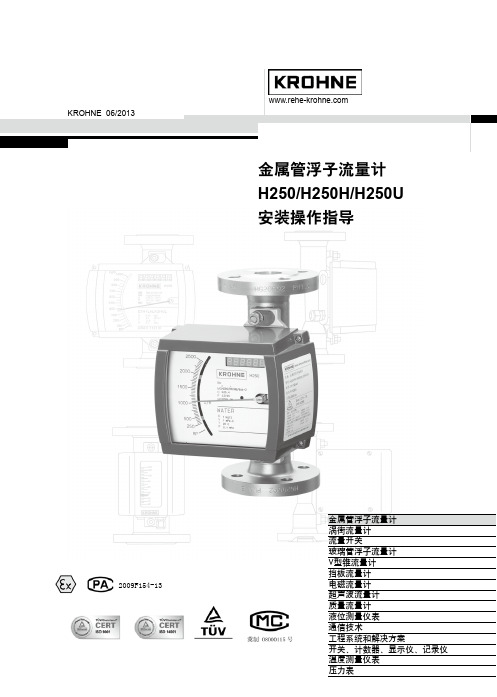
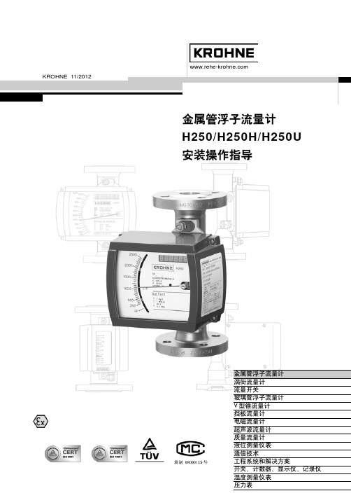
金属管浮子流量计 H250/H250H/H250U 安装操作指导
2009F154-13
金属管浮子流量计 涡街流量计 流量开关 玻璃管浮子流量计 V型锥流量计 挡板流量计 电磁流量计 超声波流量计 质量流量计 液位测量仪表 通信技术 工程系统和解决方案 开关、计数器、显示仪、记录仪 温度测量仪表 压力表
15 40 1/2″ 150/300 25 40 1″ 150/300 50 40 2″ 150/300 80 16 3″ 150/300 100 16 4″ 150/300 10Nm~1.0Kpm~7.23ft.lbf
双头螺栓
最大力矩
ANSI
DIN
ANSI
DIN
150lbs
150lbs 300lbs Nm ft.lbf
概述 .............................. 24 10.1 电气连接 ......................... 24 10.2 HARTTM通讯 .................... 25 10.3 技术参数 ......................... 26 11 流量累计器ESK-Z
克罗尼BM26磁翻版液位计说明书

BM26/B 1. 2. 3. !"#
!" !" ! !"# !"# ! !
2
3
1
!"#$%
L=304(11.97 )
DN15PN4.0
BM26/BM26G
7
BM26/BM26G
9.5 BM26 ! !"#$ ! ! ! !"#$ ! "# !"#F ! ! !" !" ! !"# !"# ! !" !"# 0.5kg/l 0.1kg/l 5.0MPa 5000mPa.s AG -40 IC/AG -40 TR ! -200 IC/TR ! -200 300~6000mm 10mm AG,IC/AG !"#$ !"# TR,IC/TR !"#$%&' 304,316L,Ti,HC,B,Φ73.3X3.05 Φ64X200mm,316L,Ti M20 1.5 DIN,ANSI,GB 14.5kg/m ( 0.6kg/100mm) ER !"#$%MS15 AG !"#$ IC/AG ER
lt100ml150bw17bm26b型磁翻板液位计采用4242的不锈钢测量管在浮力作用下测量管内的浮子跟随液面移动浮子中装有永久磁钢通过磁耦合带动磁翻板翻转从而指示液位
KROHNE 04/2009 BM26/BM26G
BM26 BM26G
!
!"# !"#$%&'
L=max.6000(19.68ft) 300(11.81)
197(7.76
30 (1.18)
1
) 30(1.18)
承德热河克罗尼仪表有限公司涡街流量计4070C资料及故障分析解决方法

6、5 Optiswirl4070:6、5、1 Optiswirl4070原理:卡门涡街原理:流体经过管道中的阻挡物后产生两列漩涡,漩涡的频率和流速成正比,通过测量涡街发声体产生的频率测出流速,然后换算为体积流量或质量流量。
即:Frequency(频率)∞ Velocity(流速)Qv(体积流量)= Area(截面积)x Velocity(流速)Qm(质量流量)= Qv(体积流量)x Density(密度)6、5、2Optiswirl4070特点:6、5、3 Optiswirl4070安装:6、5、4电源要求与连线:6、5、5按键操作方法:a) 右箭头(图中6或磁棒2):i. 正常测量状态按右箭头进入参数设置状态ii. 参数设置状态为进入下一级菜单或循环移位(选择修改位)键b) 回车键(图中5或磁棒1):i. 正常状态按回车键输入密码2,可以进入维修菜单。
密码2:6回车键、1右箭头、1回车键、1上箭头ii. 参数设置状态确认及返回(上级菜单)键c) 上箭头(图中4或磁棒3):i. 正常状态下按上箭头可以在各个显示间循环切换(包括报警信息)ii. 参数设置状态为选择或修改键20140215带CA增益新版本:6、5、7-4070C三点线性修正调整方法(现场标定):4070C带线性修正调整方法(标定站三点修正)1、标定前状态:a) 参数检查设置:i. 首先记清原设置【最好有设置清单】。
ii. 然后将参数整体设置为体积流量测量【特别注意测量蒸汽或气体带温度压力补偿场合】。
iii. 注意参数设置齐全,特别注意几项:1. Fct3.5.6操作密度设置正确。
2. Fct5.1.2 CA增益:基本按照气体和蒸汽设置为mid hi&LP;液体设置为Low。
3. Fct5.1.5 AVR增益:液体一般按默认×3;气体和蒸汽一般设置为×6。
b) Fct5.1.4设置为K lin. Off状态下进行标定【也可以设为K lin. On,并设置K1=K2=K3=K标准(Fct5.1.3),并注意visc. Cal. =Visc. Cust.(且气体一般设置为0.02,液体一般设置为1),Dens. Cal.=Fct3.5.6操作密度值】6、5、8仪表检测:●压力传感器检查测试:⏹压力传感器最高耐温80°C,对测量高温介质(如蒸汽)一定要按照规范做好保温【参加说明书中的保温要求图】。
科隆krohne OPTISWIRL 4200涡街流量计 说明书

涡街流量计OPTISWIRL 4200快速启动© KROHNE 07/2015 - 4004294401 - QS OPTISWIRL 4200 R01 zh内容2 07/2015 - 4004294401 - QS OPTISWIRL 4200 R01 zh 1 安全须知32 安装42.1 交货范围 (4)2.2 安装条件 (4)2.2.1 测量液体时应严禁的安装 (7)2.2.2 液体测量的安装方式推荐 (8)2.2.3 测量蒸汽和气体时应严禁的安装 (9)2.2.4 蒸汽和气体测量的安装方式推荐 (9)2.2.5 带控制阀的管线 (10)2.2.6 推荐安装位置 (10)2.2.7 转动接线盒 (11)2.2.8 旋转显示板 (12)2.2.9 隔热层 (13)2.3 最小进口直管段 (14)2.4 最小出口直管段 (15)2.5 整流器 (15)2.6 安装 (16)2.6.1 安装注意事项...............................................................162.6.2 夹持型仪表的安装.. (17)2.6.3 法兰型仪表的安装...........................................................183 电气连接193.1 安全指导 (19)3.2 连接信号转换器 (20)3.3 电气连接 (21)3.3.1 电源供电...................................................................213.3.2 电流输出...................................................................213.3.3 电流输入...................................................................223.3.4 二进制输出.................................................................223.3.5 脉冲输出 / 频率输出 (22)3.4 分体型的接线 (24)3.5 接地连接 (26)3.6 防护等级 (27)13 07/2015 - 4004294401 - QS OPTISWIRL 4200 R01 zh 警告与符号使用操作• 此符号标注出所有的操作提示,操作人员必须按规定顺序进行操作。
克罗尼OPTIMASS_1300

MFC 300 C 一体型
MFC 300 F 现场支架型
MFC 300 W 墙挂型
MFC 300 R 19“盘装型
分体型 分体型:转换器与传感器之间的电缆最长距离为 300m
备注:各种型式的转换器都具有相同的电子部件,可有效地减少库存量,简化库存管理。
传感器的型式
法兰型
卫生型
带加热套型
带清洗接口型
2 1st module
3 2nd module
0 no module possible 0 no module possible
1 Ex-i(Ia + Pp / Cp)
2 Ex-i(Ip + Pp / Cp)
8 no module
8 no module
A Ia
A Ia
B Ip
B Ip
C Pa / Sa
测量值的 + / -0.2%(特殊可选) 测量值的 + / -0.75%(特殊可选)
优于 0.05%
参考条件
介质 温度 工艺压力
水 20oC 1 bar(表压)
密度
测量范围 精度 精度(现场标定)
400...2500 kg / m3(液体)
3
3
+ / - 2 kg / m (S15: + / - 5 kg / m )
参数表 OPTIMASS 1300
传感器材质
测量管 法兰接触表面 法兰 压力保护外壳 前端转换器外壳 额定压力(在 20oC) 测量管 压力保护外壳
温度 工艺温度(法兰连接) 工艺温度(卫生型连接) 环境温度(一体型) 环境温度(分体型)
转换器参数
显示
带就地显示 4 个光感应操作键
流量开关(承德)
使用说明 Help 流量 Flowmeter液位 Level开关 SwitchWE77继电器安全栅 Barier流量积算仪附件 Accessories 产品型号说明2003VL01声明1:此型号说明是承德热河克罗尼仪表有限公司制造产品代码编制规则。
2:此代码应用于产品选型及订货。
3:代码解释权属于产品制造商,制造商可以根据需要调整或更改代码。
4:代码版权属于承德热河克罗尼仪表有限公司,任何单位及个人未经许可不许使用此代码,否则将追究法律责任。
使用帮助Help1:操作按钮使用鼠标完成。
单击返回首页单击图标返回上一级产品型号说明2003VL01浮子流量计 VA meter DK32、DK34DK37、DK38H250H256H257H54插入式电磁流量计 MID DWM2000吹扫装置 Purge meter KPT1KPT3涡街流量计 Vortex VFM1091VFM5090VFM3100产品型号说明2003VL01电浮筒液位计 Level meter BW25BM51LT100磁翻版液位计Level gauge BM26BM710产品型号说明2003VL01流量开关 Flow switch DW181DW182DW183DW184DWM1000液位开关 Levek switch BW17BM34产品型号说明2003VL01H250 材质 Material A 1Cr18Ni9TiS 316Ti,1.4571L 316LC Hastelloy-C4,B2T TitaniumF PTFE衬里9 特殊要求产品型号说明2003VL01A 1Cr18Ni9TiH250 口径 Size 2 DN154 DN257 DN50A DN80B DN1009 特殊要求产品型号说明2003VL01S 316Ti,1.4571H250 口径 Size 2 DN154 DN257 DN50A DN80B DN1009 特殊要求产品型号说明2003VL01L 316LH250 口径 Size 2 DN154 DN257 DN50A DN80B DN1009 特殊要求产品型号说明2003VL01C Hastelloy-C4,B2 H250 口径 Size 2 DN154 DN257 DN50A DN80B DN1009 特殊要求产品型号说明2003VL01T TitaniumH250 口径 Size 2 DN154 DN257 DN50A DN80B DN1009 特殊要求产品型号说明2003VL01F PTFE衬里H250 口径 Size 2 DN154 DN257 DN50A DN80B DN1009 特殊要求产品型号说明2003VL01H256 材质 Material A 1Cr18Ni9TiS 316Ti,1.4571产品型号说明2003VL01A 1Cr18Ni9TiH256 口径 Size 2 DN154 DN257 DN50A DN80B DN100产品型号说明2003VL01S 316Ti,1.4571H256 口径 Size 2 DN154 DN257 DN50A DN80B DN100产品型号说明2003VL01H257 材质 Material A 1Cr18Ni9TiS 316Ti,1.4571产品型号说明2003VL01A 1Cr18Ni9TiH257 口径 Size 2 DN154 DN257 DN50A DN80B DN100产品型号说明2003VL01S 316Ti,1.4571H257 口径 Size 2 DN154 DN257 DN50A DN80B DN100产品型号说明2003VL01H54 材质 Material S 316Ti,1.4571F PTFE衬里产品型号说明2003VL01S 316Ti,1.4571H54 口径 Size 2 DN154 DN257 DN50A DN80B DN100C DN125D DN150产品型号说明2003VL01F PTFE衬里H54 口径 Size 2 DN154 DN257 DN50A DN80B DN100C DN125特殊D DN150特殊产品型号说明2003VL01VFM1091连接 Connetion F 法兰式连接S 夹持式连接产品型号说明2003VL01VFM5090连接 Connetion F 法兰式连接S 夹持式连接产品型号说明2003VL01VFM3100连接 Connetion F 法兰式连接S 夹持式连接产品型号说明2003VL01BM26 材质 MaterialA 3041Cr18Ni9TiL 316L00Cr17Ni12Mo2TiTTitinium钛 FPTFE衬里PPVC塑料产品型号说明2003VL01附件accessoriesH系列附件1091系列附件5090系列附件3100系列附件BW、BM外腔体精度:4%精度:2.5%量程:水:2.5 l/h-1000l/h;空气(20 C,0.1013MPa)):0.07-28m3/h量程:水:0.63-6.3m3/h;空气(20 C,0.1013MPa)):14-170m3/h量程:水:6.3-25m3/h;空气(20 C,0.1013MPa)):80-600m3/h量程:水:25-40m3/h;空气(20 C,0.1013MPa)):350-1200m3/h量程:水:63-100m3/h;空气(20 C,0.1013MPa)):1800-3000m3/h量程:水:2.5 l/h-1000l/h;空气(20 C,0.1013MPa)):0.07-28m3/h量程:水:0.63-6.3m3/h;空气(20 C,0.1013MPa)):14-170m3/h量程:水:6.3-25m3/h;空气(20 C,0.1013MPa)):80-600m3/h量程:水:25-40m3/h;空气(20 C,0.1013MPa)):350-1200m3/h量程:水:63-100m3/h;空气(20 C,0.1013MPa)):1800-3000m3/h量程:水:2.5 l/h-1000l/h;空气(20 C,0.1013MPa)):0.07-28m3/h量程:水:0.63-6.3m3/h;空气(20 C,0.1013MPa)):14-170m3/h量程:水:6.3-25m3/h;空气(20 C,0.1013MPa)):80-600m3/h量程:水:25-40m3/h;空气(20 C,0.1013MPa)):350-1200m3/h量程:水:63-100m3/h;空气(20 C,0.1013MPa)):1800-3000m3/h量程:水:2.5 l/h-1000l/h;空气(20 C,0.1013MPa)):0.07-28m3/h量程:水:0.63-6.3m3/h;空气(20 C,0.1013MPa)):14-170m3/h量程:水:6.3-25m3/h;空气(20 C,0.1013MPa)):80-600m3/h量程:水:25-40m3/h;空气(20 C,0.1013MPa)):350-1200m3/h量程:水:63-100m3/h;空气(20 C,0.1013MPa)):1800-3000m3/h量程:水:2.5 l/h-1000l/h;空气(20 C,0.1013MPa)):0.07-28m3/h量程:水:0.63-6.3m3/h;空气(20 C,0.1013MPa)):14-170m3/h。
克罗尼转子流量计H250安装维护手册
KROHNE 11/2012
!"#$% H250/H250H/H250U !"#
s
!"#$% !" ! !"#$% !" !" !" !"# ! !"# ! !"#$%& ! ! !"#
!"#$%&'(
H250 !"#$%&'()$*+, !"#$%&'()*+,-. !"#$%&'()*+,-. !"#$%&'()*+,-./0+123)456 !" !"#$% ! !"# 39 !"#$%&'()*+,-./012345 ! " #$%&
!"
H250
!"#
7
! H250H ! !"W
!"#$%&'
!"#$%&'()*
!"#$ !"#$%&
!"#!$%&'(')*+,-#./0$123
=2.
=
!"#$%&'()*+,-#$./ ! !"#$ !"# 1:2 !"#$ !"# 1:5 1:2 9 !" !"# #$% TIV C4
!"# $ ! DIN 2501 DN mm 15 25 50 80
!"#$%&'()*+,$-./012 !" G M9
TT电子Roxspur测量与控制SC250流量计说明书

Metal Tube Flowmeters SC250Features Continued:•Flow rate (model SC250)• Water: 16 l/h — 30m 3/h • Air: 500 NI/H — 900Nm 3/h• Accuracy: 2.5% (q G =50%) / 1.6% (q G =50%) on request•Connections:• Model SC250: DN15 — DN80• EN1092-1 or ANSI flanges. Other flange standards on request (JIS,…) • Threaded connections BSP or NPT• Other connections available on request• Materials: EN 1.4404 (AISI 316L), other materials available on request • Local indication •Options:• 1 or 2 limit switches• Electronic transmitter with 4-20mA analog output for safe or hazardous area (EX ia IIC T4 or T6 protection,ATEX certified). HART protocol available on request• Local volume totalizer. Remote volume totalizer by means of pulse output (not available for Ex transmitters)Description:Flowmeters are based in the variable area principle. The metering system consists on a calibrated orifice and a conical float. The force from the fluid, as it flows from the bottom to the top, displaces the float until it reaches an equilibrium point that is a function of: • E = force of the fluid flow • Pf = weight of the float • AI = free area of flow(AI= Ao, calibrated orifice area, - Af, float area)Each float position represents an area between the float and the orifice. This area corresponds to a flow rate.Applications:• Water treatment plants, pulp & paper and food industry • Pharmaceutical, chemical and petrochemical industry • Power plants and nuclear generating plants • Heating and cooling circuits • Saturated steam circuits•Oven treatments and control of gas burnersFeatures:• Metallic tube with a robust construction • Indication by means of magnetic coupling• High performance measurement in extreme working conditions and highresistance to corrosion • Low pressure drop• Damping mechanism to avoid float bounces in gas and steam applications Ao = calibrated orifice area Af= float areaPf= weight of the float E= force of the fluid flow AI= Ao -Af = free area of flowModel SC250 Technical DataWorking PressureMaterials3217 65 4Connections:• DN15...DN80 EN 1092-1 flange or ANSI equivalent.Other flange standards on request (JIS,…) • Threaded connections BSP or NPT Housing:• IP65—coated aluminum . EN 1.4404 (AISI 316L)with glass window, on requestOperations:• Vertical with upwards flow (BD)Limit Switches and Transmitters:• SC -AMD1...2: 1 or 2 adjustable inductive detectors(+ relays on request)• TH7T Ex...: 4-20mA transmitter + totalizer 2 wiresEx ia IIC T4 or T6 (ATEX). HART protocol is available on request. DN15...DN80The tapered floats are constructed in AISI 316L as standard or other materials on request, according to the characteristics of the process fluid.The maximum working viscosity for these floats is 10 mPa •s approx., depending on flow rate.Dimensions Models SC250Threaded connection BSP/NPT (EN 1.4404)DimensionsDimensionsFlow RangesAdjustable limit switch SC-AMDNAMUR (EN 60947-5-6) 3.5mm slot type inductive detectoractivated by vane, mounted in the indicator housing.• SC-AMD1...2: 1 … 2 adjustable limit switches• Power supply: 8 VDC• Ambient temperature: -25°C —+70°C• ATEX certificate Ex ia IIC T6Control relay (on request)NAMUR (EN 60947-5-6) for 1 or 2 inductive detectors.• Power supply: 24...253 VAC 50-60Hz24...300 VDC• Input: NAMUR Ex ia IIC• Output: 1 or 2 relay contacts• Output rating: 2A 250VAC 100VA / 1A 24VDC• Ambient temperature: -20°C —+60°CSC-AMD Modular housingTransmitter and TotalizerTransmitter TH7TThe TH7T electronic transmitters provide an analog output proportional to the flow rate and a digital output. They include a display for volume totalization. They are based on the Hall effect and mounted inside the indicator housing. • TH7T Transmitter + totalizer• Optional HART protocol version available • TH7TH Transmitter + totalizer + HART protocol TH7T ExBoth limit switches AMD and electronictransmitters TH7T can be mounted together in the same housing.The TH7T Ex transmitters belong to group II. They are intended for use in potentially explosive atmospheres, except in mining.ATEX version (EX ia IIC T4 or T6) Technical data• ATEX certificate Ex II 1 GD• Power supply: 14...30VDC, 2-wire system• Power consumption: 4-20mA for 0… 100% of scale • 4-20mA analog output:• Error: <0.6% of magnet position• Maximum load in 4-20mA loop: 900Ω (with 30VDC power supply)• Totalizer: 8 digits, 4.5mm high. Reset by potential freecontact• Ambient temperature: -5°C — 40°CFloat Damping System(For gas and steam applications)Ceramic, PEEK or metallic piston system for avoiding float oscillations in flowmeters for gas and steam service, obtaining stable readings even with very low working pressures and low gas densities. Available for DN15...DN80 1. Upper float stop 2. Float 3. Piston4. Piston locking circlip5. Guide cylinder6. Circlips for locking upper float stop & guide cylinder123 4 5 6Quality management System ISO 9001 certified by Pressure Equipment Direction 97/23/CE certified by ATEX European Directive 94/9/CE certified byHART is a registered trademark of HART® Communication Foundation。
- 1、下载文档前请自行甄别文档内容的完整性,平台不提供额外的编辑、内容补充、找答案等附加服务。
- 2、"仅部分预览"的文档,不可在线预览部分如存在完整性等问题,可反馈申请退款(可完整预览的文档不适用该条件!)。
- 3、如文档侵犯您的权益,请联系客服反馈,我们会尽快为您处理(人工客服工作时间:9:00-18:30)。
M9指示器附加部件
9 限位开关Kmin, Kmax, k2 概述.............................. 21
9.1 电气连接 ......................... 21 9.2 限位点设置....................... 22 9.3 限位开关K的确定 ............... 23 9.4 技术参数 ......................... 23 10 电信号输出ESK2A(HARTTM)
H250安装操作指导
5
■ 磁过滤器用于含有铁磁微粒的介质。磁过滤器必须安装在流量计的上游。过滤器由螺旋排 列的磁棒组成,这样可以最大限度减少压力损失。所有磁棒表面都带有防腐的PTFE包层。 磁过滤器有两种类型:
F型
FS型
法兰连接 长100mm
夹紧连接 长50mm
适用于所有仪表尺寸:材质为1Cr18Ni12Mo2Ti。 ■ 选择与法兰额定压力或操作压力相对应的螺栓和密封垫(用户自备)。同时还要注意它们的
6
H250安装操作指导
电缆葛兰 1用堵头密封不用的接口 2将葛兰头拧紧 3留出滴水弯
隔爆型电缆接头的安装 EXD型指示器标准接头为直接引入电缆,如左下图示。接线完成后,必须将压紧盘3拧 紧,保证密封效果,否则可能因为泄漏造成安全事故! ■ 不能随意更换其它的密封圈,如果有损坏,应及时和我们联系。 ■ 严禁现场无压紧电缆装置供电工作! ■ 如果现场有电缆保护套管,可以选择右下图所示的电缆密封装置,同样需要拧紧压紧盘5。
2
H250安装操作指导
目
H250流量计,机械指示器
1 H250流量计的安装 1.1 安装要求............................ 5 1.2 管道准备............................ 5 1.3 管道安装............................ 5 2 启动 2.1 液体的测量.......................... 8 2.2 气体的测量.......................... 8 3 流量表 3.1 H250/RR,H250/ 哈氏合金C4 ...... 9 3.2 H250/ 陶瓷 .........................10 3.3 H250 H .............................11
DIN 2501 ANSI B 16.5 (入口)压力
防腐性能和热稳定性。 注意:法兰的内径与标准尺寸有一定偏差(见第14页),要适当扩大垫圈的内径。 ■ 将垫圈对准后,将螺母拧紧。 ■ 带PTFE衬里的测量管,为防止密封面的损坏和密封的可靠性,请按下列要求拧紧法兰螺母:
标准尺寸 DIN 2501 ANSI B 16.5 DN PN mm bar inches lbs
概述 .............................. 27 11.1 电气连接 ......................... 27 11.2 设置 .............................. 28 11.3 技术参数 ......................... 29
量部件由一个金属锥管或高纯度A L 2 O 3陶瓷孔板组成,浮子在其中能够自由地上下移动。随 着流量大小的变化浮子在测量管中的垂直位置也发生相应的变化。浮子的位置通过磁传递系 统传送到M9指示器刻度盘上。这种类型的流量计特别适用于各种不利的环境和介质条件。
工作原理
流量计的工作原理为浮子原理。H250的测量部件由一个金属锥管或高纯度AL2O3陶瓷孔 板组成,浮子在其中能够自由地上下移动。流量计的安装方式为底进上出垂直安装。
13.3 流量累计器ESK-Z .............34
13.4 高温型..........................34
13.4.1 指示器的安装 ..................35
13.5 零部件明细表 ..................35
14
防爆证书 ......................36
2. 启动
■ 流量计正常工作需要一个确定的最低工作压力(入口压力)。
介质名称
压力损失与工作压力 (入口压力)的比率
液体
1:2
气体(不带阻尼器)
1:5
气体(带阻尼器)
1:2
关于压力损失,参见第9页的流量表。 ■ 测量气体时,在下列条件下必须给TIV浮
子配一个阻尼器(仅对于250/RR和C4)
仪表尺寸
最大工作
15 40 1/2″ 150/300 25 40 1″ 150/300 50 40 2″ 150/300 80 16 3″ 150/300 100 16 4″ 150/300 10Nm~1.0Kpm~7.23ft.lbf
双头螺栓
最大力矩
ANSI
DIN
ANSI
DIN
150lbs
150lbs 300lbs Nm ft.lbf
从顶部方向看,保温材料1只能到达壳体2,不能包住壳体。电缆进出口3部位必须留 出足够的自由空间。
H250安装操作指导
7
特别注意H 2 5 0 H水平型流量计的安装,指示器应该位于管线的侧面,而不是在管道 的上面,并注意流体的流向要和指针指示由小到大的摆动方向一致,否则会造成测量 值的不准确,如下图所示:
21-38
12
最高介质和环境温度表 ........ 30
13 服务-M9指示器的改装
13.1 限位开关 ....................... 31
13.1.1 加装第二个限位开关 ...........32
13.2 M9指示器输出ESK2A ......... 32
13.2.1 ESK2A的更换及设定 ..........33
维护和维修
录
5-19
3.4 H250 U ...........................12 4 仪表类型.......................... 12 5 技术参数.......................... 13 6 证书............................... 14 7 尺寸和重量 ....................... 14 7.1 H250/RR, H250/C4............... 14 7.2 H250/陶瓷 ........................ 17 7.3 H250 H ........................... 18 8 更换部件 8.1 浮子更换.......................... 19 8.2 增加浮子阻尼器................... 19 8.3 零部件明细表 ..................... 19
1.1 安装要求 系统的实际操作压力不能超过订单中指定的操作压力。测量管法兰上用钢字打印的额定
压力不一定与检测压力相等(参见订货文件或仪表有关说明)。 ■ 确保打湿部件(测量部件)的材质适用于被测介质(参见第12页)。 ■ 环境温度和介质温度不能超过指定的最大值(参见第13页,技术参数)。 ■ 变面积流量计必须垂直安装在管道上(浮子测量原理,流向:向上)。 ■ 流量计法兰的公称尺寸应与管道的尺寸一致。 ■ 为防止管道张力,配对法兰必须与管道轴向对中并且相互平行。 ■ 水平流量计安装时应使度盘表面垂直于地面, 介质流向为流量增加时指针摆动方向。
可随仪表一同提供的文件和配件
H250流量计发货时可根据要求提供: ■ 安装操作指导 ■ 认证文件-防爆证书 ■ 不包括安装附件(螺栓、法兰垫圈、电缆)
质量及售后服务承诺
供方保证所提供的设备和材料是全新的,未使用过的,完全符合买方规定的规格和性 能要求。供方在所有设备的保质期内,如发生设备问题,在接到用户通知的24小时内作出 响应,同时委派专业工程师解决问题,凡属质量问题原因,应及时给予免费更换。
概述 .............................. 24 10.1 电气连接 ......................... 24 10.2 HARTTM通讯 .................... 25 10.3 技术参数 ......................... 26 11 流量累计器ESK-Z
4×M16 8×5/8″ 8×3/4″ 39.0 28.2 34.0 24.6
为保证仪表的防护和防爆功能的实现,在安装中必须注意:
■ 用仪表提供的密封圈,如果有损坏,应及时更换。 ■ 按规定线径使用电缆。 ■ 为避免凝露流进指示器壳体,在防水接头处要留出滴水弯。 ■ 拧紧防水葛兰2,保证内部的密封圈将电缆抱紧密封,不允许用胶布之类缠绕密封。 ■ 不用的电缆接口用专用的堵头1密封。
Nm ft.lbf
4×M12 4×1/2″ 4×1/2″ 9.3 6.7 3.5 2.5
4×M12 4×1/2″ 4×5/8″ 22.0 15.9 6.7 4.8
4×M16 4×5/8″ 4×5/8″ 55.0 39.8 24.0 17.4
4×M16 8×5/8″ 8×3/4″ 47.0 34.0 43.0 31.1
KROHNE 06/2013
金属管浮子流量计 H250/H250H/H250U 安装操作指导
2009F154-13
金属管浮子流量计 涡街流量计 流量开关 玻璃管浮子流量计 V型锥流量计 挡板流量计 电磁流量计 超声波流量计 质量流量计 液位测量仪表 通信技术 工程系统和解决方案 开关、计数器、显示仪、记录仪 温度测量仪表 压力表
标准电缆接头 1-壳体 2-密封圈 3-压紧盘
4-电缆 5-压紧垫片 如果需要管道保温 适用于各种类型的指示器。