胜达因高速泵介绍.
高速泵

www.tyjx.ne t
专家视点 EExxppeerrttVViieeww
以下 、固 体颗粒 小于 0. 1mm的 各种 液体泵也能正常运行。
4) 采用独特的叶轮流入口和 在广阔 转速及流 量范围内依 然有效 的螺距 递增的诱 导轮相匹配 ,使泵 在 高 转 速 下 仍 具有 卓 越 的 吸 入 性 能,即NPSHr 值低。
通用机械
卧式小 型高速泵 ,该系列产 品包括 P-1000型、P- 2000型、 P-3000 型三大类。 为适应 世界各地 化肥业 ( 尿 素生 产 ) 的 需 要, 19 67年 开 发 了 卧 式 超 大 功 率、 超 高 扬 程 高 速 泵 - HMP5 112 型 泵 ,功 率 最 大 为1 150k W,扬程最高为4 573m。 1984年又 开发了 HMP5112小 型化产 品 - HMP3 000 型 高 速 泵, 功 率 最 大为579kW,扬 程最高为 3 000m。 HMP 型 高 速 泵 是 由 两 个 单 级 高 速 泵 串 联 或 并 联 而 成的 , 代 表 了 当 代高速 泵的最高 水平,最高 转速达 25 000r/ mi n。除了胜德斯特兰公司, 英格索兰公司也推出了HS P-5150、 5200、7200三个系列高速泵。
表1 立式高速泵主要参数
流量 / (m3/ h)
3~100 3~60 3~100
扬程
/m 200~1 920 100~915 200-1 920
转速 / (r / mi n) 4 800~23 700 5 000~14 179 9 400~23 700
电动机功率 / kW 160 37 355
型号
GSB-W2 GSB-W3 GSB-W5
胜达因高速泵介绍

齿轮制造工艺
• 切齿坯 • 滚齿机成形齿廓 • 热处理, 齿面渗碳 • 磨齿到最终尺寸 • 按 AGMA 11级公差检查
轮齿的硬度
• 齿廓硬度对齿轮的 性能很重要:
– 坚硬的外部保证了 接触面的强度及长 久的使用寿命
– 柔软的内部保证了 齿的抗弯韧性
齿轮检查
• 空间尺寸采用德国 蔡思三座标测量仪 检验
提高离心泵扬程
泵壳
叶轮
部分发散型
锥形扩散器
泵壳
扩散器 喉部
导叶
叶轮
全发散型
压力 速度
部分发散型 全发散型
部分发散型 全发散型
泵流量的调节
• 调整进口孔径尺寸以适合额定流量 的介质流入
• 调整叶轮流道尺寸以适合额定流量 的介质通过
• 调整出口喉管 / 涡壳尺寸以适合额 定流量的介质流出
泵的比转速
4 = 400 HP / 300kW (341)
泵壳
1 = 3”x 2”, 600# Flange (311, 801, 331, 341) 2 = 3”x 2”, 600# Flange (322, or 802) 3 = 6”x 4”, 600# Flange (313 or 333 Hi-Flow) 6 = 3”x 2”, 300# Flange (806)
胜达因泵规格
高速泵的基本原理
高速泵的起源...
• 十九世纪五十年代后期,波音公司因需 求一种特殊的泵而求助于胜特兰宇航公 司
• 为波音707飞机设计,用于增加起飞推 力的注水泵
• 在飞行时干转
• 工况为100 加仑/23 立方米/小时 ,1100 英尺/330 米
胜特兰公司的第一台高速泵
• 采用德国工程师巴斯克开创的 “非常 规” 泵设计方法
胜达因-无泄漏磁力泵

今天的磁力驱动泵
磁力泵工作原理
液体流出 出口
液体进入
磁力泵工作原理
隔离罩 叶轮 外磁缸 内磁缸 轴承箱 联轴器
电机
底板
无泄漏磁力驱动离心泵 标准的壳体和叶轮 (ANSI & ISO)
无泄漏磁力驱动离心泵 隔离罩
胜达因--无泄漏磁力驱动离心泵 胜达因--无泄漏磁力驱动离心泵 -泵轴 / 轴承 / 轴承座
胜达因磁力泵内转子设计
集装式组件
胜达因磁力泵密封形式
单静密封垫片
泵壳
叶轮
其它磁力泵厂
两处密封点
压差开关
泵的保护和状态监 测
温度探头
52
Power = kW (%) Max. Limit (%) Min. Limit (%) Start Timer (S) Reaction Timer (S) Hysteresis (%) Current Range (A) Mode Relay On Reset
GSA/I 系列
流量: 流量:-720 m3/h 扬程: 扬程:-200m 温度范围: 40℃ 260℃,低温 温度范围:-40℃~ 260℃,低温 型可达型可达-100℃ 材质:316,Alloy 20,哈氏合 材质:316, 20,哈氏合 :316 金等 产品特点:零件互换性最大, 产品特点:零件互换性最大, 泵型号最少 应用范围:通用输送型,以适 应用范围:通用输送型, 应于教宽的工艺范围和各种应 用场合。 用场合。
胜达因-无泄漏流体输送技术的世界领导者
胜达因-无泄漏流体输送技术的
世界领导者
HMD/Kontro 磁力驱动泵 •ANSI标准 ANSI标准 ANSI •ISO/DIN标准 ISO/DIN标准 ISO/DIN •API-685标准 APIAPI 685标准 胜达因 610高速泵 API 610高速泵 ANSIMAG •氟塑料衬里磁力驱动泵 氟塑料衬里磁力驱动泵 •Caster 磁力驱动泵 Caster 胜达因API 617高速 胜达因API 617高速 压缩机
API610及相关中国泵标准介绍-航天所解析

API610及相关中国泵标准介绍国家特种泵阀工程技术研究中心中国航天科技集团公司第十一研究所(京)高速泵事业部阎殿甲1.API610(第八版)简介 1.1 API610是国际著名离心泵标准目前,世界上最权威的泵标准化组织有三个:即美国标准协会ANSI(American National Standards Institute)所属的B73标准;国际标准化组织ISO(InternationalStandards Organization)所属的TC-115标准;美国石油学会API(American Petrochemical Institute)所属的610标准。
在三大著名标准中,由于API610是专门为石油、化工行业编制的离心泵标准,而且是全面总结炼厂和化工厂中的泵设计或泵制造引发的事故和教训而制订出来的,所以许多专家都认为API610标准是鲜血和智慧的结晶,因而在石油、化工和天然气工业用离心泵方面最具权威性。
API610标准对泵的设计和制造质量要求非常严,所以按API标准生产的泵价格也高,因为质量成本增加了。
1.2 API610标准简介第八版API610标准于1995年8月出版。
该标准中详细规定了范围、术语、关联标准等总则;压力泵壳、作用在管口上的力、转子、轴封、轴承、材料等基本设计;驱动机、联轴器、底座和仪表等副机和附件;检查、试验和发货;各种特定型泵和卖方资料等章节。
第八版与第七版比较有6点不同:(1)在章节上由原来的5章增为6章,即多出了“特定型泵”1章;(2)在名称上也有变更,由原来的“一般炼厂用离心泵”改为“石油、重化学和天然气工业用离心泵”;(3)在度量衡单位方面,第八版的主单位采用SI国际单位制,以US美制单位为辅助单位,在()内给出了参考换算值;(4)第八版给出了各国适用的标准比较表;(5)第八版还给出了各国的材料标准比较表;(6)第八版在动力学、轴振动,特别是机封方面增加了新内容。
胜达因HMP-3512高速泵密封失效分析
胜达因HMP-3512高速泵密封失效分析发布时间:2021-11-11T08:16:54.005Z 来源:《中国科技人才》2021年第23期作者:赵跃[导读] 我公司一段高压丙烯进料泵是由一台两级高速泵、驱动透平(电机)、齿轮箱、公用油站和一套公用密封系统组成。
身份证号码:3426221****8200815 南京先进生物材料与过程装备研究院南京 210000摘要:我公司使用的胜达因HMP-3512型号高速泵自开工调试以来,泄漏严重,拆检多次发现密封动静环碎裂,磨损严重,通过研究分析发现是由停机过程中密封反压导致的,最终提出了改变频电机来解决该问题。
关键词:高速泵;透平;电机;密封;反压;变频1.基本情况我公司一段高压丙烯进料泵是由一台两级高速泵、驱动透平(电机)、齿轮箱、公用油站和一套公用密封系统组成。
高压丙烯进料泵01P0216A/B/C共3台,其中01P0216A为透平驱动,01P0216B/C为电机驱动。
正常生产时01P0216A/B同时运行分别给喷射泵01J0217A/B提供动力源,01P0216C平时作为备用泵。
该丙烯高速泵是美国SUNDYNE公司HMP-3000系列的2级高速离心泵,具体参数如下1.1密封系统该高速泵的2级均采用串联密封,密封系统分为两个单独流程:1)冲洗液:1级和2级的各级冲洗液流量为1.14m3/h,冲洗液来自2级出口,分为两路经孔板减压至1级和2级主密封,对密封起到清洁和降温的作用。
2)缓冲液:密封缓冲液系统为单独撬装,主要包括2台齿轮泵、1个缓冲液灌、双联过滤器(5μm)、双联水冷器。
密封缓冲液为royal purple barrier fluid type GT22。
缓冲液自泵出口经孔板先到2级密封,从2级密封出来再经孔板至1级密封,各级缓冲液流量为1.14m3/h。
1.2密封系统设计参数2.故障现象自泵组试车调试(2017年6月)开始至2018年6月,透平驱动的A泵密封泄漏量稳定,一级密封液外漏约5滴/分钟,二级泄漏约10滴/分钟,未更换过密封,电机驱动的B泵更换过3次密封,电机驱动的C泵更换过一次密封,B泵和C泵每次发现泄漏丙烯都是发生在停泵切换的时候,发现密封系统管线结霜严重,有大量丙烯泄漏致密封罐。
传“道” 授“业” 解“惑”——记2011泵业技术高峰论坛
下 面选 取演讲 嘉宾 的部 分精 彩发 言 内容 ,与未 能赶 来参加 此次 泵技 术 高峰论坛 的广大读者们分享一 下。
体成本等好处 。格 兰富E 泵在 工业应 用 中更可 实现 客 户化定 制 、灵活 配 置 、功能 强大 、 工厂设 置 、权限 设
艺 的加 速利 用等 。介绍 了泵 技术现
状 、泵 面临 的挑 战和泵 及其 系统的 能 耗 分 析 及 其 节 能途 径 。列 举 了
几个火 电厂循 环水 泵节能 改造 的案
演讲嘉宾关醒凡先生 认真聆听并记录☆
希望今后 通过!
持续下 去 ,办成 品腊 列论坛 ,成为泵 业及
题 。列 举 了部分 典型 的行业 应用 ,
2 年 第 01
1第 wy . 5 年6 wx ’ 期Ⅵ.n 一 , ' 9 t j
e t
麓
。
脚
如应用在 泵行 业 、污 水处 理及物 流
~
封可以 独立维 护 、 叶轮与壳体 间的
泵的安 全可靠性 与t 交流技术 发展 ,探i
演讲 人 :格 兰 富水泵 ( 海 ) 上 有 限公司产品经理 王强
演 讲题 目 :格兰 富E 即装 即用 泵
嘉 宾发言及精心 的组 织 ,在全天7 位 嘉 宾 的演讲 过程 中 ,会议 现场 的气 氛 都十 分热 烈 。环 保展E6 一M3 会 6 议 室能容纳 10 ,而论坛 现场签到 2人
最优 化 ,使再循环 量和振 动最 小减 小超 过额定 流量 的功率 ,从而可选
测市场形 势 ,让 用 性 的同时 ,使制造 解 了产 品在 实 际 中 况 ,寻找技 术 、管 增加 了沟通的 有效1 1
胜达因MASO SINE泵

胜达因MASO SINE泵
MASO SINE泵——
性能卓越,是高粘度,超低剪切输送的最佳选择
胜达因旗下的MASO泵公司研发的Sine(正弦)回转式容积泵,是容积泵领域中真正意义上的少数创新之一,它成功地解决了食品卫生行业中浆料输送的难题。
Sine正弦泵通过了国际通行的3A认证,正弦式转子实现了轻柔平稳、无剪切的物料输送,专利的进口设计使之具有强大的吸入能力。
全球每天有数千台MASO泵成功运行在食品、化妆品、医药、化工等各个领域。
我们的产品
大流量输送
流量可高到100,000l/h
吸入能力
吸入压力可达0.85bar
超低剪切输送
即使含有大量固体物质和易碎产品,仍可安全无破坏性输送
高粘度性能
达到流动能力的极限,超过100,000cp
无脉冲输送
精确调节流动容积,无干扰震动,装料机可均匀供应稳定产品量
即时维护
避免停工时间
十年担保
为MASO SINE泵主要部件提供担保
特定应用灵活性
通过MASO特殊标准件-可选系统实现
生产品质保证
通过DIN EN ISO 9001,TüV认证
综合服务
通过外部服务销售建议和高效的合作性服务来确保最佳的使用性
HMD/Kontro无泄漏磁力驱动泵
CASTER无泄漏磁力驱动
ANSIMAG无泄漏磁力驱动泵胜达因高转速离心泵
胜福罗高压离心泵
AnySpeed泵
胜达因工艺气压缩机
胜达因工艺气压缩机。
阐述LMV-311型高速泵

阐述LMV-311型高速泵1 概述神马实业股份有限公司下属分公司的精苯装置是采用美国莱托法工艺,通过催化加氢,精制粗苯。
现有高速泵9台,其中6台是LMV-311型,1台是GSB-L1型,2台是LMV-322型。
高速泵具有结构紧凑、检修方便、性能优越、高扬程、大流量、运转可靠、性能高等特点,近年来在石化行业得到广泛应用,逐步取代了故障率高、易泄漏的柱塞泵和往复泵。
高速泵采用呈直线放射形的完全敞开式叶轮,其具体型号、参数如下表1所示。
2 LMV-311型高速泵机械密封泄露的故障分析及保障方案2.1 LMV-311型高速泵机械密封系统的原理2.2 LMV-311型高速泵机械密封泄露的故障分析精苯装置脱除H2S系统中的高速泵(F-P401A/B),在生产中泵的机械密封经常泄露。
起初,我们认为是机械密封的质量或者机械密封的安装等方面的问题;后来发现旧的机械密封积存有较多的炭颗粒,才意识到是由于活性炭粉碎后的小颗粒引起的。
活性炭粉碎后,就进入到物料中。
由于机械密封的冲洗液是泵自身的物料,这些小的炭颗粒随冲洗液进入并沉积到机械密封中,就阻碍了机械密封弹簧的补偿作用,加剧了机械密封动静环的不规则磨损,使机械密封在很短的时间就失去了作用。
同时,还会对高速泵的叶轮等其他过流部件造成冲刷,缩短这些过流部件的使用寿命。
2.3 LMV-311型高速泵机械密封泄露的保障方案鉴于活性炭粉碎后对机封产生的危害,我们不使用活性炭过滤器,在LMV-311型高速泵前增加两台并联的精密过滤器,过滤工艺系统中的颗粒杂质。
经过多年生产实践的验证,通过改善LMV-311型高速泵的使用工况,延长泵的运行周期和泵备件的使用寿命。
3 高速泵在启动前及运行时的故障分析及保障方案长期生产中LMV-311型泵经常出现齿轮箱润滑油的乳化问题。
F-P201是带机封冷却冲洗水的高速泵,冲洗水排放有两个阀门,正常情况下PORT2排水,PORT1排油。
调节冲洗水入口阀至排放口PORT2水流呈细线状或液滴状连续排出。
贝朗医疗
请针对医疗客户-贝朗医疗开展客户背景分析,了解内容如下:1、客户公司的完整名称贝朗医疗(上海)国际贸易有限公2、客户公司概况以及行业知名度;贝朗贝朗集团成立于1839年,是世界知名的专业医疗设备、医药产品以及手术周边产品供应商之一。
贝朗公司在建立和传递医疗专业知识方面有着悠久的历史和传统。
秉承致力于医疗现代化、持续创新及以客户为导向的理念,贝朗集团从160年前的医药零售店发展为今天在全球50多个国家建立了分支机构,并拥有32,000名员工的专业医疗保健公司。
贝朗集团包括四个核心事业部:- 医药部:提供全面的输液治疗方案- 蛇牌部:是外科的伙伴- 护理产品部:为院外病人提供产品和咨询服务- 透析部:提供透析治疗系统贝朗医疗拥有170年历史,是世界领先的专业医疗设备、医药产品以及手术周边产品供应商,在全球50多个国家建立了分支机构,拥有超过38,000名员工。
贝朗丰富的历史造就了我们独特的企业文化,与客户和员工紧密相关,并融入对社会和人文的认知和责任。
贝朗公司在建立和传递医疗专业知识方面有着悠久的历史和传统,秉承致力于医疗现代化、持续创新及以客户为导向的理念“专业共享”是贝朗品牌信守的承诺:通过对公司内、外专业知识技能的传播,服务和满足医疗行业与广大患者的需求,并将持续通过共享来拓展这些专业知识和技能。
专业共享是指导我们行动的原则,是我们在公司内或与客户的交流中建立专业合作关系,鼓励双向知识分享的基础。
贝朗品牌建立于三个核心价值之上:创新、效率及持续帮助我们传达“专业共享”的理念和承诺贝朗医疗(上海)国际贸易有限公司成立于1999年12月,是贝朗医疗大中国区总部。
随着公司扩展,我们在中国主要城市如北京,成都,广州,香港,沈阳,武汉等地设有分支机构,共有员工800多人。
通过外高桥保税区的物流中心,我们得以进口集团公司的产品并实现在中国地区的配送。
于2000年10月设立的技术服务中心则为中国地区的客户提供了更好的售后服务。
胜达因磁力泵总介绍

GSA/I 系列
流量:~720 m3/h 扬程:~200m 温度范围:-40oC~260oC,低温 型可达-100oC 材质:316,Alloy 20,哈氏合金等 产品特点:零件互换性最大, 泵型号最少 应用范围:通用输送型,以适 应于教宽的工艺范围和各种应 用场合.
Company Confidential 内部资料,汉胜版权所有,翻录仿用必究
可逆扭矩损失 普通钐钴 1.5级 高性能钐钴 2.17级 Sm2Co17
钕铁硼 Nd2Fe14B
不可逆扭矩损失
居里温度
500oC
600oC
700oC
钕铁硼
钕30%, 铁 68.7%, 硼 1.3% 1990年出现 温度限制在 120 oC内 国内厂家使用
Company Confidential 内部资料,汉胜版权所有,翻录仿用必究
磁力泵/屏蔽泵
机械密封
一般应用 低 市场大小
Company Confidential 内部资料,汉胜版权所有,翻录仿用必究
密封
HMD/Kontro 磁力驱动技术
Company Confidential 内部资料,汉胜版权所有,翻录仿用必究
简单的磁力驱动泵
Company Confidential 内部资料,汉胜版权所有,翻录仿用必究
防干转功率 保护器
液体泄漏探头
Company Confidential 内部资料,汉胜版权所有,翻录仿用必究
防干转功率保护器
停车或报警:泵干转, 料罐抽空 小流量, 关阀操作
52
Power = kW (%) Max. Limit (%) Min. Limit (%) Start Timer (S) Reaction Timer (S) Hysteresis (%) Current Range (A) Mode Relay On Reset
日机装圣达因高速泵操作维修手册SndPump-LMV-311-IOM

SUNDYNELMV-311 PUMPSInstruction and Operation ManualMay 2006CopyrightAll rights reserved. No part of this publication may be reproduced, stored in a retrieval system or transmitted in any form or by any means, electronic, mechanical, photocopying, recording or otherwise without the prior permission of Sundyne Corporation.© 2006 Sundyne CorporationWarrantySundyne Corporation warrants to Buyer for a period of twelve (12) months from the date of being placed in service (but not to exceed eighteen (18) months after the date of shipment) that the equipment at the time of shipment will be free from defects of design, material and workmanship. If any defects or malperformance occur during the warranty period, Sundyne’s sole obligation shall be limited to alteration, repair or replacement at Sundyne’s expense, F.O.B. Factory, of parts or equipment, which upon return to Sundyne and upon Sundyne’s examination prove to be defective. Equipment and accessories not manufactured by Sundyne are warranted only to the extent of and by the original manufacturers’ warranty. Sundyne shall not be liable for damage or wear to equipment caused by abnormal conditions, vibration, failure to properly prime or to operate equipment without flow or caused by corrosives, abrasives or foreign objects. THE FOREGOING WARRANTY IS EXCLUSIVE AND IN LIEU OF ALL OTHER WARRANTIES, WHETHER EXPRESSED OR IMPLIED INCLUDING ANY WARRANTY OF MERCHANTABILITY OR FITNESS FOR ANY PARTICULAR PURPOSE. In no event shall Sundyne be liable for consequential or incidental damagesContentsContents (ii)INTRODUCTION (1)Sundyne Centrifugal Pumps (1)Text Symbols (1)Equipment and Safety Precautions..2 Wearing Personal Protective Equipment (2)Using Forklifts (2)Ensuring Electrical Safety (2)Testing Equipment (2)Using Chemicals (3)Protection from Falling (3)Preventative Machine Guards (3)EXPLOSION/FIRE HAZARD (3)Pre-Commission Checklist (3)Familiarizing Yourself with the Pump3 Driver Instructions (3)Verifying Auxiliaries (3)Installing a Seal Environmental Control System (4)Checking Driver Rotation (4)Piping Connections (4)Start-Up Checklist (5)Pressurizing the Fluid Loop (5)Servicing the Gearbox (5)Auxiliary Lube Pump (5)Setting the Valves (5)Control Checklist (5)Verifying Operating Conditions (5)Adjusting the Cooling Flow (5)Installation and Start-Up Checklist (6)INSTALLATION (8)Inspection.................................................8Storing Your Pump Short-Term (8)Storing Your Pump Long-Term (8)Suction and Discharge Piping (9)Seal Environmental Control System10 Liquid Buffer System (10)Mounting Vertical Units Without Stands (10)Mounting Vertical Units with Stands (LMV) (11)Base Mounted (BMP) Units (11)Driver and Coupling (11)Flexible Coupling for LMV Units Without a Vertical Stand (12)LUBE SYSTEM (13)Lube System (13)Gearbox Heat Exchanger (13)Oil Manifolds (13)Remote Heat Exchanger (14)Gearbox Sump (14)SundGard® Oil Filter (14)Main Lube Pump and Lube Oil Priming Kit (15)Oil Pressure (15)START UP (16)Start-Up Procedures (16)Controlling the Pump During Startup (17)Single Operation (17)Parallel Operation (17)OPERATION & CONTROL (18)Operation of Sundyne Pumps (18)Suction Conditions (18)Minimum Flow Conditions (18)Entrained Gases (18)System Head Curve (18)Parallel Operation (19)MAINTENANCE (20)Disassembly of LMV-311 (20)Inspection, Cleaning and Repair (32)Inspecting All Bearings (32)High-Speed Shaft (32)Gearbox Mechanical Seal (32)Shaft Sleeve (33)Bearing and Shaft Clearances (33)Reassembly of the LMV-311 (34)Procedure for Checking the High-Speed Shaft Endplay (48)TROUBLESHOOTING (50)Gearbox & Pump Diagnostics (50)Pump Mechanical Seal Diagnostics52 SPECIFICATIONS (54)Falk Steelflex Type Coupling Specifications (54)Falk Double Gear Type Coupling Specifications.......................................54Falk Double Gear Type-Vertical Specifications (55)Thomas Type DBZ Coupling Specifications (55)Thomas SN Spacer Type Vertical & Horizontal Coupling Specifications56 Gearbox Lube Oil Specifications (57)Gearbox Parts List (58)Gearbox Replacement Parts (59)Gearbox and Pump Torque Values.60 Mechanical Seals (61)Pump Disassembly Replacement Parts (63)Pumps Parts List (64)Double Seal Arrangement and Parts (65)Single Seal Arrangement and Parts66 Tandem Seal Arrangement and Parts (67)Separator Arrangements (68)Pump and Gearbox Cross Section (Single Seal Arrangement) (69)LMV-311 Gearbox (Exploded View).70 Pump Casing and Seal Housing (Exploded View) (71)Gaskets (72)INDEX (73)INTRODUCTION Sundyne Centrifugal PumpsSundyne pumps provide high-energy performance and competitive efficiencies in an industrial quality, compact unit that is simple to maintain. Sundyne pumps are single stage that utilize an integral gearbox. Designed to increase the pressure of a continuous flow of fluid by applying centrifugal action, Sundyne pumps are most commonly used in HPI, CPI, and Boiler Feed applications. Commonly applied in refineries, petrochemical plants, and power generation plants, Sundyne pumps are used in high-head, low-to-medium flow processes. This manual presents installation, servicing, troubleshooting, maintenance and spare parts information for the latest configuration of Sundyne centrifugal pumps.Note: Parenthetical numbers included in the text correspond to item numbers on theillustrated figures. The correct sparepart can be ordered for any generationpump by referencing the item and serialnumbers.Text SymbolsThe following symbols may be found in the text of this manual.They have the following meanings:WARNING: Text accompanied by thissymbol indicates that failure to followdirections could result in bodily harm ordeath.ELECTRICAL HAZARD: Textaccompanied by this symbol indicatesthat failure to follow directions could resultin electrical damage to equipment orelectrical shock. RECOMMENDED: Text accompanied by this symbol indicates recommended usage.REMINDER: Text accompanied by this symbol indicates a reminder to perform an action.EQUIPMENT USE ALERT: Text accompanied by this symbol indicates that failure to follow directions could result in damage to equipment.Equipment and Safety PrecautionsSundyne Corporation manufactures centrifugal pumps to exacting International Quality Management System Standards (ISO 9001) as certified and audited by Lloyd’s Register Quality Assurance Limited. Genuine parts and accessories are specifically designed and tested for use with these products to ensure continued product quality and performance. Sundyne cannot test all parts and accessories sourced from other vendors; incorrect design and/or fabrication of such parts and accessories may adversely affect the performance and safety features of these products. Failure to properly select, install or use authorized Sundyne pump parts and accessories is considered misuse and damage or failure caused by misuse is not covered by Sundyne’s warranty. Additionally, modification of Sundyne products or removal of original components may impair the safety of these products and their effective operation.CAUTIONSundyne pumps may handle hazardous, flammable, and/or toxic fluids. Proper personal protective equipment should be worn. Precautions must be taken to prevent physical injury. Pumpage must be handled and disposed of in accordance with applicable environmental regulations.Note: Safety procedures must be appliedprior to any installation, maintenance,or repair of a Sundyne pump. Failure tofollow safety precautions may lead toinjury!Wearing Personal Protective EquipmentTo ensure safety, protective equipment must be worn at all times when installing, performing maintenance, or repairing equipment. The following safety recommendations must be adhered to for optimum safety:• Safety glasses, with the minimumrequirement of side shields, must be wornat all times.• Steel-toed shoes must be worn when lifting equipment greater than 15 pounds(7 kg) or if pallet jacks or forklifts areoperated.• Hearing protection is stronglyrecommended at all times when noiselevels exceed 85 dB during an eight (8.0)hour period.Note: Chemical resistant gloves must be used if chemicals are utilized (refer to UsingChemicals for additional information). Note: A dust mask respirator must be worn if chemicals have warning labelsregarding fumes, dust, or mists.When using more than one piece of protective equipment, consider their compatibility. For example, safety glasses will not interfere with hearing protection equipment. Be sure to clean all pieces of personal protective equipment immediately after each use.Using ForkliftsAny persons operating a forklift must have an active recognized operator license.Note: Before initializing forklift operation,verify that the lift is in a safe operatingposition.Ensuring Electrical SafetyAll electrical sources must be powered-off before installation, service, or repair of equipment occurs.Note:Sundyne recommends that a Lock-out/Tag-out program be followed priorto altering the equipment. Locks ortags must be provided to warnemployees that equipment istemporarily unavailable.Once all work has been completed, the person installing the lock or tag must remove it according to company procedure.Testing EquipmentPrior to performing a test on newly installed, maintained, or repaired equipment; all personnel in the immediate area must be warned. Note: Follow company procedures prior toequipment testing at all times.Using ChemicalsAny chemicals to be used must be accompanied by a relevant material safety data sheet (MSDS), in accordance with government legislation. If applicable, use chemical proof gloves.Note: An eye wash station (or equivalent)should be available in the event ofinjury. If any hazardous or flammablechemicals pass through the equipment,a complete decontamination of theequipment is required.Protection from FallingFall protection and associated preventative measures are required when working on equipment located six feet or higher from the ground.Note: Follow company fall preventionprocedures prior to working onequipment.Preventative Machine Guards Preventative guards must remain in place on all equipment.Note: Only remove the guards whileperforming maintenance or repair. Replace the guards immediately after working on the equipment and prior to start up.EXPLOSION/FIRE HAZARD Note:Never use an acetylene torch, open flame, or heat to attempt to removeparts that have seized together inSundyne equipment. Any residualprocess gas or liquid that is flammablecan result in an explosion or fire withpotential for serious injury or death.Pre-Commission ChecklistFamiliarizing Yourself with the Pump Before servicing and starting up the Sundyne pump, carefully review all information on the product, including:• Specification sheets• Outline drawings• Performance curves• Instruction and related manuals• System P&ID/Process Flow Diagram (Clients equipment)• Control system and operationalphilosophy/narrative (Client) Familiarize yourself with the pump configuration before starting and operating the pump.Driver InstructionsCarefully follow all installation and starting instructions provided by the driver manufacturer. This information is included in the final data package. Verifying AuxiliariesBefore start up, verify that the following auxiliaries are met:• Check the utility connections• Verify that the auxiliary piping conforms to Sundyne standards, as indicated inthe detailed specifications• Verify all switch and instrumentconnections• Verify that all switch and instrument settings are set to normal operatingstandards• Calibrate all measurement equipment, such as flow meters, ampere meters,and pressure meters, etc.Instruction and Operation ManualInstalling a Seal Environmental Control SystemInstall a system to control the seal environment. Also, verify that port 1 is properly vented.If required, install drain piping overhead to ensure that the environment operates under normal conditions. For more information, contact Sundyne Corporation.Checking Driver RotationIf the driver is coupled, un-couple; then verify that the direction of the driver rotates in the same direction as the arrow stamped or cast on the pump casing. If the driver is splined, check the direction of the motor fan.Piping ConnectionsVerify that the following bolted or threaded connections are tight:• Pump flange bolts• Seal environment piping and portconnections• Cooling water connections to heatexchanger (if applicable)• Gearbox oil drain plug• Pump case drain plugStart-Up ChecklistPressurizing the Fluid LoopPressurize the double seal buffer loop or external seal flush, if applicable, prior to admitting fluid into the pump casing. Servicing the GearboxFill the gearbox with lube oil up to a quarter inch (¼) or 6 mm from the top of the oil level sight glass.Note: Prior to using lube oil, verify that itconforms to acceptable lube oils pec ification standards. Refer to theSPECIFICATIONS section in thismanual for more information.Under normal operation, the lube oil level will lower about a quarter inch more than when idle. Additionally bubbles will appear at the top of the sight glass.Note: Sundyne recommends that gearboxlube oil be changed at least every sixmonths.For requirement information about priming the lube oil system, refer to the start-up section in this manual.Auxiliary Lube PumpIf your pump includes an auxiliary lubrication pump, unlock the electrical circuit and move it to the “hand” position. Check for oil leaks and recheck the oil level.Setting the ValvesTo set the pump to the designated operating point, start the pump with the suction valve in the open position while throttling the discharge valve.Control ChecklistVerifying Operating Conditions Verify the following parameters against the specifications on the specification sheet: • Suction pressure• Suction temperature• Discharge pressure• Total head• Flow rate• Power consumption• Specific gravity• Viscosity• Net Positive Suction Head (NPSH) The status of these conditions will significantly alter performance of the pump if they are not in accordance with the specification sheet.Check with your Sundyne representative if the operation conditions of your pump must run under different parameters than indicated by the specifications on the specification sheet. Adjusting the Cooling FlowIf your model pump includes an installed heat exchanger for the gearbox, adjust the cooling flow to keep the temperature of the gearbox sump at 140°-160°F (60°-71°C). Maximum recommended temperature is 180°F (82°C).Installation and Start-Up ChecklistNote: Lock out all switch gears, including main driver, auxiliary lubrication system and instrumentation before working on this equipment.This checklist is NOT intended to be inclusive. You must read and follow: instruction manuals, outline drawings, specification sheets and curves for this equipment during installation, commissioning, and operation. Your total satisfaction is our goal. Please call with any questions or comments. Be sure to have the unit serial number that is imprinted on the gearbox nameplate, and request “Sundyne Field Service”.Is all the information underlined above readily available?Are the following bolted/threaded connections tight?o Pump flange bolts?o Seal environment piping and port connections?o Cooling water connections to heat exchanger(s)(if applicable)?o Gearbox oil drain plug?o Pump case drain plug?There are two types of connections between the motor and gearbox; a splined shaft or a coupling. For splined connections, the splined shaft must be lubricated with the supplied splinegrease and the two o-rings installed prior to mounting the motor. It is recommended that the input shaft be rotated by hand prior to mounting the motor. If the unit has a coupling, be sure thecoupling gap is correct and bolting between coupling halves is tight. This instruction manualcontains coupling set-up information. It is not necessary to align the coupling for run-out orflatness as this is controlled by the rabbet fits on the gearbox and coupling adaptor.Is a check valve installed in the discharge line?Is Port 1 open to atmosphere or piped to safety drain or flare or vent header? (Back pressure must not exceed 5 psig).Note: A drip leg must be used if the Port 1 connection rises from the seal housing.Are all other seal system ports identified and connected according to the outline drawings?Is gearbox filled to within ¼” (6.35mm) of the top of the sight glass with the approved oil and the breather fitting installed? Oil capacity is 7 quarts (6.6 liters). Is the needle valve on the gearboxpressure gauge open? Removal of the vent plug below the fill/vent fitting will speed filling.Has the oil filter, heat exchanger, and related piping been filled with oil (primed)?Do process conditions, suction pressure, suction temperature, discharge header pressure, and specific gravity agree with specification sheet information? DO NOT test the pump on waterunless it is designed for water. Check with your representative or Sundyne Corporation if youmust test on a different fluid than shown on the specification sheet.If you have auxiliary lubrication pump, unlock the electrical circuit and start it in the “hand”position. Check for oil leaks and recheck the oil level. If the process suction pressure exceeds460 psig (32.3 kg/cm2g), the auxiliary lube pump should be running prior to and anytime thesuction is pressurized.Prior to starting the unit, have you opened the suction valve fully and discharge throttled to allow design flow, typically 40-50% open? Check the control valve to be sure it is functional. Inspect the case drain, ports, and flanges for leaks. Has the pump been vented through Port 6? Open bothsupply and return valves supplying cooling water to the gearbox heat exchanger. Check suction pressure to be sure it agrees with the specification sheet.Unlock the main driver circuit and bump the motor. Rotation is CCW as viewed from the top end of the motor. Is rotation correct? Once rotation is verified, run motor for 1 second on, 20 seconds off. Do this several times until gearbox oil pressure gauge shows pressure, then start the main driver. Oil pressure will be between 15-60 psig (1.1-4.2 kg/cm2g) depending on the type ofbearings in the gearbox. After commissioning, bumping the motor is not required.If pressure control is being used, throttle the discharge valve immediately after start-up. Does the discharge pressure agree with the specification sheet? If flow control is being used, adjust thevalve until flow agrees with the design value listed on the specification sheet.Once the gearbox oil temperature has stabilized, adjust cooling water supply until the oil temperature is 140-160°F (60-71°C) on units equipped with heat exchangers. Maximumrecommended temperature is 180°F (82°C).Listen for any unusual noises or pressure fluctuations.Note: If you have any questions or concerns about these procedures or the information supplied, please call your representative or Sundyne Corporation.INSTALLATIONInspectionImmediately inspect your Sundyne product upon receipt of the equipment. Check for any damage, which may have occurred during shipment. Notify the carrier and Sundyne immediately if damage is evident. Note:The input shaft on the pump may not turn freely due to seal drag and speedincreasing gear meshes. If the inputshaft does turn freely, and if rotation is“not smooth,” damage may haveoccurred during shipping.Storing Your Pump Short-TermIf your Sundyne pump is not to be installed immediately, protect it from exposure to moisture and dust. Do not remove the factory installed shipping covers for casing flanges and seal ports. Ensure that the shipping covers be kept securely in place.Note: Observe the storage instructionsprovided by the driver manufacturer.Storing Your Pump Long-TermIn addition to the precautions in the short-term section above, additional precautions are required for long-term storage.If your Sundyne pump will not be operated for a period of time exceeding six months from the date of shipment, long-term storage conditions must be met to ensure minimum corrosion damage to the gearbox and fluid-end components.Note: Sundyne does not accept liability for equipment damaged during the storageperiod. Sundyne does not guaranteethe quality of equipment during andafter the storage period.To ensure the original quality of the Sundyne pump after storage, all components must be inspected by an authorized Sundyne service engineer. Components that are not manufactured by Sundyne (except mechanical seals) must be inspected by its own manufacturer.Note: Any inspection fees are the soleresponsibility of the purchaser.Factors which affect the quality of a Sundyne pump, when stored, are:• Humidity• Temperature• Surrounding chemicalsLong-term storage methods must prevent damaging conditions from making contact with the internal components of the equipment. When the equipment is stored in strong chemical environments or near salt water, protection must occur immediately upon receipt of the equipment.Recommended Long-Term Storage ProceduresSundyne recommends that you do the following to prevent damage to your pump during long-term storage:1. Store your pump only in an indoor, climatecontrolled building. These conditions willmaintain constant temperature and humidity.2. Perform inert gas purging of componentinternals.3. Ensure oil flooding of gearbox internals.4. Use desiccant bags.Note: Because long-term storage ofequipment is of a highly critical nature,it is recommended that Sundyne becontacted to provide more details onthe above procedures.Suction and Discharge PipingPlease adhere to the following best practices for installing and maintaining suction and discharge piping:1. Install a suction (35-40 mesh) strainer andclean the suction line prior to starting thepump. This procedure will protect theimpeller from damage by mill scale, welding slag, or other foreign particles during initialstartup.Note: Sundyne Recommends installation of a differential pressure instrument acrossstrainer to indicate strainer condition. 2. When installing piping to the pump, ensurethat all piping is supported independentlyfrom the pump.3. All piping must always line up with the pumpflanges.Note: Never use force to position piping into place at the flanged suction anddischarge connection locations. Failureto have piping properly aligned mayimpose excessive strains on the unit. 4. Sundyne recommends using a straight pipeassembly of at least three times the lengthof the pipe diameter.Note: Carefully select the size of pipe andfittings to be installed so that frictionlosses will remain low.5. Never use a suction pipe that is smaller indiameter than the pump suction inlet.6. Sundyne recommends installation of adischarge check valve to prevent reverserotation.7. Use block valves (both suction anddischarge) when isolating the pump duringshutdown. This practice will minimizeprocess leakage and prevent possiblereverse rotation from pump back-flow.8. It is recommended that suction anddischarge pressure gauges be installed onany pump that is not flow controlled. If noflow measuring device is installed there is no way to determine accurately where on itscurve the pump is operating.Seal Environmental Control SystemA seal environmental control system may be required depending upon the pump seal arrangement and application.Always maintain the pump seal environment as detailed on the specification sheet that accompanies each unit.Note : For most applications, a standardcontrol system can be obtained from the factory.Ensure that the specified seal environmental control system is properly installed and that the ports are open (or plugged) as indicated in Figure 1.Note : Port 1 must always be open so that it isfree to drain.Figure 1. Seal Housing Port IdentificationLiquid Buffer SystemFor double liquid seals and tandem liquid seals, a liquid buffer system is used. Introduce the buffer liquid into port 7, which will flow through the seal cavity, and out from port 2.Buffer flow should be 0.5 to 3 gpm (2 to 12 liters/min) with an inlet temperature of 60o to 120o F (16o to 49o C), and inlet pressure asindicated on the pump specification sheet. The liquid must be clean to 5 microns.Mounting Vertical Units Without StandsFor all vertical units without stands, a mounting base is recommended. The pump should be mounted on a rigid foundation, secured in position by one-inch diameter bolts. The boltsshould be installed in the foundation as shown on the installation drawing. The length of the bolts should be sufficient to extend at least ½-inch above the nut.Instruction and Operation ManualMounting Vertical Units with Stands (LMV)Grouting of the base plate is required for all vertical stand units. The top of the stand (driver mounting surface) should be leveled by shimming under the base prior to grouting the channels that are to be filled with grout through the access holes. The nuts on the foundation bolts should not be tightened until the grout has set for at least 48 hours.Base Mounted (BMP) UnitsGrouting of the base plate is required on all BMP units. The base plate should be leveled prior to grouting. After grout has been applied, it must be allowed to set for at least 48 hours before tightening foundation bolts.Driver and CouplingDrivers are normally shipped separately from the gearbox and pump. When a splined interconnecting shaft is supplied, this shaft must be lubricated at each end with one tube (5cc) of anti-fretting compound (Sundyne Part Number MP01AA10). Also available are solid shaft drivers coupled to the gearbox with a flexible coupling. Drivers are to be installed and maintained in accordance with the manufacturer’s instructions.Flexible Coupling for LMV Units Without a Vertical StandNote : Lock out the driver starting switchbefore working on the coupling. When installing flexible couplings, use those supplied by Sundyne to ensure tolerance ofparallel and angular misalignment, and axial end float. Use flexible disc couplings or gear type couplings if not using those supplied bySundyne. Coupling installation for turbine drivers is identical to that for motors.The gearbox coupling hub is normally mounted at the factory. The driver coupling hub is mounted on all motors and turbines shipped directly from Sundyne.Driver Coupling is Not MountedIf your product is received without the driver coupling hub mounted, use the following procedure when installing Falk or Thomas couplings:1. Measure the distance from the top surfaceof the gearbox hub, to the datum face of the driver adapter. This measurement is referred to as dimension”X”.Figure 2. Dimension X2. Determine the end gap (the distancebetween each coupling hub) for the size of coupling provided. Refer to the Coupling Specifications tables in the Specifications section of this manual for specific measurements. 3. Subtract the end gap value from dimensionX to determine the distance from the driver datum face to the coupling hub face. This value is referred to as dimension “Y.”Figure 3. Dimension Y4. Scribe the shaft to show dimension Y.5. Ensure that the coupling hub bore, keyways,and shaft are clean and free from burrs. Also determine that the key fits in the keyways. 6. Heat the hub in an oil bath or oven toapproximately 250o F (121o C),or more if necessary, so that the hub will slide onto the motor shaft. 7. Position the hub at the scribed line on theshaft. 8. Tighten the hub key set screw.Note : Before the hub is installed onto theflexible disk couplings, verify that the coupling bolts and washers can be assembled (Figure 4) from the motor side of the hub when installed. If these pieces do not assemble, insert short bolts with bevel washers into the hub flange before fitting them onto the shaft. Figure 4. Assembly of Coupling Bolts andWashers。
4413高速泵齿轮油在胜达因泵上的应用

报 告 预 计 . 国石 油 需 求将 继 续保持 增 长 态 势 , 计 全 年 石 油 表 观 消 费 量 达 49 我 预 .3亿 吨 , 比上 年 增 长
5 增 速低 于近 1 %, 0年 平 均水 平 71 2 1 .%。 0 1年我 国的石 油表 观 消 费量为 4 . 7亿吨 。 0 2年 我 国石 油进 口量 21 将 继 续增 长 . 对外依 存 度将 进 一步提 高
表 1 41 4 3高 速 泵 齿 轮 油 与进 口油 的 典 型 性 能 比较
从 表 1可 以 看 出 ,4 3高 速 泵 齿 轮 油 具 有 闪 41 点高, 粘温 性好 , 氧化 安定 性 和润 滑性 优 良的特点 , 其综 合性 能达 到 国外 同类产 品 的技术 水 平 。 完全 能 满 足胜达 因 高速泵 的使 用要求 。
胜 达 因泵 (u d n u ) sn y ep mp 最早 用 于 宇航 工业 ,
近 年 首先 由美 国 开 发 为 民用 ,广 泛 用 于 乙烯 、 涤 纶 、 烃 和加 氢 裂化 等 装 置 。 达 因泵 主要 由美 国 芳 胜
定性 。 以确 保较 长 的使 用 周期 。此 外还 要求 油 品具 有 良好 的润 滑性 和抗 泡 沫 性 能 以确 保 泵 体 不被 磨 损, 并使泵 体 的温升 不超 过规 定 的要 求 。 1 41 4 3高 速泵 齿轮油 的性 能
L u Yu ha i e o
( u r a t o p n h n qn rn h Snp c C o g i 0 0 9 C ia L bi n m a yC o g igB ac ,io e , h n qn 4 0 3 , hn ) c C g
Ab t ac :The p a tc la p i a in s we ha h e r o lf rhih-s e d pu 41 s a l o me t sr t r c i a p lc to ho d t tt e g a i o g p e mp 4 3 wa b e t e t e l rc t e uie n s o u d ne p mp, n t e vc e id c u d b p t 0 0 0 h. h ub i a i r q r me t fs n y u ng a d is s r i e p ro o l e u o 1 0
API610及相关中国泵标准介绍-航天所

API610及相关中国泵标准介绍国家特种泵阀工程技术研究中心中国航天科技集团公司第十一研究所(京)高速泵事业部阎殿甲API610(第八版)简介1.1 API610是国际著名离心泵标准目前,世界上最权威的泵标准化组织有三个:即美国标准协会ANSI(American National Standards Institute)所属的B73标准;国际标准化组织ISO(International Standards Organization)所属的TC-115标准;美国石油学会API(American Petrochemical Institute)所属的610标准。
在三大著名标准中,由于API610是专门为石油、化工行业编制的离心泵标准,而且是全面总结炼厂和化工厂中的泵设计或泵制造引发的事故和教训而制订出来的,所以许多专家都认为API610标准是鲜血和智慧的结晶,因而在石油、化工和天然气工业用离心泵方面最具权威性。
API610标准对泵的设计和制造质量要求非常严,所以按API标准生产的泵价格也高,因为质量成本增加了。
API610标准简介第八版API610标准于1995年8月出版。
该标准中详细规定了范围、术语、关联标准等总则;压力泵壳、作用在管口上的力、转子、轴封、轴承、材料等基本设计;驱动机、联轴器、底座和仪表等副机和附件;检查、试验和发货;各种特定型泵和卖方资料等章节。
第八版与第七版比较有6点不同:(1)在章节上由原来的5章增为6章,即多出了“特定型泵”1章;(2)在名称上也有变更,由原来的“一般炼厂用离心泵”改为“石油、重化学和天然气工业用离心泵”;(3)在度量衡单位方面,第八版的主单位采用SI国际单位制,以US美制单位为辅助单位,在()内给出了参考换算值;(4)第八版给出了各国适用的标准比较表;(5)第八版还给出了各国的材料标准比较表;(6)第八版在动力学、轴振动,特别是机封方面增加了新内容。
第八版涵盖了6种悬臂式泵的基本形式,即:OH1-底脚安装式泵;OH2-中心线安装式泵;OH3-独立轴承座立式管道泵;OH4-刚性联轴器传动立式管道泵;OH5-共轴传动立式管道泵和OH6-与高速齿轮箱成一整体的立式泵。
知名低温泵和压缩机品牌总汇
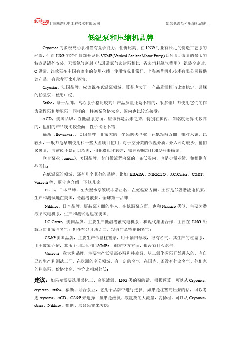
低温泵和压缩机品牌Cryomec的多极离心泵相当有竞争能力,性价比高;在LNG行业有长足的制造工艺泵的经验,针对LNG的特性特别开发出VSMP(Vertical Sealess Motor Pump)系列泵。
该泵的最大的特点是罐外安装,无需氮气密封(与通常氮气密封泵相比,省去消耗氮气费用),铠装全密封,O泄漏。
该款泵在中国有较多的使用业绩,使用情况非常好。
上海塞普机电技术有限公司提供该产品,有意者可来电咨询。
Cryostar,法国品牌,应该说在低温泵领域,算是老大了,产品质量相当比较稳定,常规的低温泵,使用广泛;Sefco,瑞士品牌,离心泵价格比较高!产品质量还是不错的,很多钢厂都使用它们的作为流程泵和增压泵,同样的,柱塞泵价格太高,国内也比较难接受;ACD,美国品牌,在低温泵方面,应该算是后来之秀,特别在国内,知名度还算比较高的,他们的产品线比较全面;性价比还不错;福斯(flowsever),美国品牌,非常大的一个泵阀类企业,在低温泵方面,相对来说,比较少,一般都是早期使用和一些大型项目使用,对于空分类的低温介质,介入相对较少;他们多级泵,应该说还是可以考虑,但价格也比较高,需要根据项目和型号来确定;联合泵业(union),美国品牌,专门做流程内泵的,在低温内,也是少量业绩,和福斯有些类似;在低温泵的领域,还有几个其他的品牌,比如EBARA、NIKKISO、J.C.Carter、CS&P、Vanzetti等,顺带也介绍一下这几家;Ebara,日本品牌,在大型水泵领域非常出名,在低温泵方面,主要是低温潜液电机泵,生产和测试地在美国,低温潜液泵,全球第一品牌;Nikkiso,日本品牌,屏蔽泵方面的牛人,在低温泵方面,也和Nikkiso类似,主要为潜液泵式电机泵,生产和测试地也在美国;J.C.Carter,美国品牌,主要生产低温潜液式电机泵,和现代集团合作,主要在LNG船载方面非常有名气;但在空分介质方面,没有什么特别的名气;CS&P,美国品牌,主要生产低温柱塞泵,用于油田领域,很有名气,其生产的柱塞泵,用于液氮介质,其压力可以达到180MPa;但在空方方面,也没有什么名气;Vanzetti,意大利品牌,主要生产低温离心泵和柱塞泵,从二氧化碳泵开始进入的,有自己的生产和测试工厂,在欧洲的空分领域,有一定的名气,在国内,还没有什么名气。
世界知名泵业比较
世界知名泵业比较Grandview 赵锋博美国FLOWSERVE,美国Flowserve公司成立于1997年,在收购了世界著名的美国英格索·德莱赛泵公司之后,成为世界泵业第二大巨头,该公司泵年销售额约10亿美元。
旗下的美国达高华特是一家专门生产化工、石油化工和其它工业领域用泵、阀门的制造厂商。
而旗下另一家公司的英格索·德莱赛泵公司(简称IDP)是世界上最大的离心泵专业生产商之一,已有100多年制造离心泵的历史。
目前,IDP公司已有12个制造厂向中国电站、油田开发提供各种型号的泵。
近几年,该公司每年都要向中国市场提供近千万美元的泵产品及相关设备。
ITT流体技术公司,生产各种泵(给水泵、废水泵、污水泵、工业流程泵、空调泵、排水泵、消防泵、矿用泵、发电用泵、船用泵、医药和生物加工用泵、航空用泵)、热交换器、阀门、仪表和控制设备。
瑞典ITT Flygt公司目前主要生产以下三大类产品,包括潜水泵、污水泵和大型泵。
其应用领域主要包括污水处理、农业水利、建筑、工业及矿山等部门。
法国磨锐MORET,Ensival-Moret是最早应用于中国大亚湾电站的核电站用泵。
德国KSB,KSB在中国泵阀产品的市场占有率已达15%。
2005年底,KSB制造的世界最大型冷却水泵落户中国,并在中国市场获得总值约7亿元人民币的订单,主要包括锅炉给水及循环水泵、冷却水泵和辅助泵等产品。
格兰富、丹麦格兰富是世界上最主要的泵类产品制造商之一,其生产量达每年一千万台。
循环泵(UP),潜水泵(SP)和离心泵(CR)为三大主要类型泵。
格兰富是世界上最大的循环泵生产制造厂,此类泵产品覆盖了大约50%的世界市场。
2005年11月1日,格兰富(Grundfos)集团接管南非水泵制造商Brisan Turbo (Pty) Ltd,Brisan,其在南非市场份额大约为35%。
同时,格兰富公司计划在2006年向中国投资11亿丹麦克朗,这将成为其公司历史上最多的年度投资额。
胜达因高速泵介绍

02
胜达因高速泵技术参数
性能参数
流量
高效率的叶轮设计,确保了泵在各种工况下 的高流量输出。
转速
根据不同的应用需求,可以选择不同的转速, 以满足特定的流量和扬程需求。
扬程
优化的流道设计,使得泵在提供高扬程的同 时保持较低的能量损失。
功率
根据泵的大小和性能要求,可以选择合适的 电机功率。
结构参数
叶轮
提升安全性
防爆设计
根据使用环境和介质特性,胜达因高速泵采 用防爆设计,提高设备使用的安全性。
自动保护功能
具备过载保护、过压保护、过流保护等多重自动保 护功能,确保设备运行安全可靠。
可靠密封
采用可靠的机械密封和密封材料,防止介质 泄漏和外部杂质进入泵内,提高设备的安全 性。
延长使用寿命
高耐磨材料
关键部位采用高耐磨材料,提高设备的耐久性和可靠性, 延长设备使用寿命。
02
03
运行
维护
在运行过程中,应定期检查泵的 运行状态,确保无异常振动或噪 音。
定期对泵进行检查和维护,包括 更换磨损件、检查密封件等,以 延长泵的使用寿命。
03
胜达因高速泵的优势与 价值
提高效率
高效叶轮设计
胜达因高速泵采用先进的叶轮设 计,能够提高泵的效率,减少无 谓的能量损失。
优化流道
通过优化泵的流道,减少流体在 泵内的阻力,降低能量损失,从 而提高泵的效率。
加强与上下游企ห้องสมุดไป่ตู้的合作,形成完整的产业链,实现共赢发展。
THANKS FOR WATCHING
感谢您的观看
采用精密铸造的叶轮,具有高强度和 耐腐蚀性,确保了泵的长寿命和可靠 性。
泵壳
工业用机油产品手册

-5-
长春嘉路喜实业集团有限公司
SHT-518 合成高温链条油
性能特点 ◎ ◎ ◎ ◎ ◎ 优良的高温稳定性,使用温度可达 250℃ 润滑抗磨损性突出,可承受较重负荷 结焦少,链条可长期保持清洁状态 黏温性能好,机器低温易启动 挥发少,能有效节约润滑油料,不污染环境,改善工作条件
技术规格
产品符合以下规格: ◎ Q/SH PRD233—2008 应用范围 ◎ 适用于纺织印染行业的国产及进口热定型机、拉伸拉幅机、印花定型机等高温 链条传动系统的润滑 ◎ 适用于建材行业的高温烘房、汽车及其它烤漆烘房、喷涂线干燥箱等高温链条 传动系统的润滑 ◎ 适用温度范围:-20℃~250℃ 典型数据 项目 运动黏度,mm /s 40℃ 100℃ 黏度指数 中和值,mgKOH/g 闪点(开口) ,℃ 凝点,℃ Noack蒸发(250℃,1h) ,% 国外性能相当的产品 ◎ 使用性能与德国 KLUBER 公司的“Hotemp plus”相当
2
SHT-518合成高温链条油 313.1 25.7 108 0.08 270 -32 2.0
-6-
长春嘉路喜实业集团有限公司
注意事项 ◎ 勿与其他润滑油混用,不同润滑油之间可能会发生物理或化学反应导致使用 性能降低 ◎ 使用后及时封盖以避免水分、灰尘等杂质的混入 ◎ 使用在与橡胶、塑料、油漆等非金属材料接触的润滑部位时,事先应进行材料 相容性试验 ◎ 若要更换不同的油品,应等油箱中的油用完后,再加入另一种油 包 装 ◎ 4L 塑料桶、200L 铁桶或根据客户需求进行包装
-2-
长春嘉路喜实业集团有限公司
SH618 烤漆链条专用高温润滑油
性能特点 ◎ 具有黏度指数高、黏温性能好的特点,既能满足烘房高温润滑的要求,又能保证 在常温下启动 ◎ 具有较高的闪点,可保证设备安全工作 ◎ 具有在热氧化条件下发生分解反应,裂解成小分子物质的性能,使链条及轨道 积炭极少,且清焦容易 ◎ 特殊的分子结构使得产品具有良好的油漆相容性,不会造成烤漆面形成鱼眼、 缩孔,也不会在烤漆面产生色差,对烤漆附着力无不良影响 应用范围 ◎ 适用于汽车烤漆烘房高温链条的润滑,也适用于其它需要烤漆烘房的场合 ◎ 最高使用温度为 200℃ 典型数据 项 目 运动黏度,mm /s 100℃ 40℃ 黏度指数 酸值,mgKOH/g 闪点(开口) ,℃ 蒸发度(200℃,2h) ,%质量分数 腐蚀(45#钢,100℃,3h) 注意事项 ◎ ◎ ◎ 包 ◎ 在贮运和使用过程中,应防止杂质和水分混入 请勿与其它油品混用 在高温下有一定蒸发损失,使用时要特别注意打开风道,以免发生事故 装 3.5kg/塑料桶、16kg/200L 铁桶装或根据客户需求进行包装
胜达因高速泵介绍

胜达因泵
Partial Emission Pump部分发散型
SEAL HOUSING
密封腔
(INTEGRAL DIFFUSER)整体式扩散器
机械密封
节流衬套THROTTLE
MECHANICAL
BUSHING
SEAL
ROTATING 动环
FACE
INTEGRAL
DIFFUSER
COVER
整体式扩散器
比转速值
Sep 22-23, 2008
效率 Vs 比转速
部分发散
全发散
轴向
效率
Sep 22-23, 2008
比转速
独特的低比转速设计
工艺条件: _
100 gpm @ 600 ft. head 22.71 m3/hr @ 182.9 meters
NS 泵转 速
典型弗朗西斯闭式叶轮的性能
393 3560
高速轴径向轴颈 轴承
从动小齿轮
加油呼吸器
止推轴承( 滑动)
油位视镜
高速轴径向 轴颈轴承 润滑油机械密封
平衡式工艺介质机械 密封(图示为带节流 环的单端面密封)
按用户工况低比转速 流体力学设计
两步齿轮增速
• 由于增加了中间轴,输入轴和输出轴在一条直线上
输入齿轮 输入轴
中间轴
输出齿轮 输出轴
中间轴输入齿轮
2160 152
-200 to 750 -130 to 400
230 52
1450 – 17,100
1440 101
-200 to 750 -130 to 400
380 86
1450 - 3600
720 50
-40 to 350 -40 to 175
- 1、下载文档前请自行甄别文档内容的完整性,平台不提供额外的编辑、内容补充、找答案等附加服务。
- 2、"仅部分预览"的文档,不可在线预览部分如存在完整性等问题,可反馈申请退款(可完整预览的文档不适用该条件!)。
- 3、如文档侵犯您的权益,请联系客服反馈,我们会尽快为您处理(人工客服工作时间:9:00-18:30)。
Sep 22-23, 2008
用于大流量的弗朗西丝式叶轮
闭式叶轮
Sep 22-23, 2008
理论扬程计算公式:
2 U HT = g
HT = 理论扬程 (m.) U = 叶轮端速 (m/sec.) g = 加速度 = 9.8 m./sec.
叶轮端速 (U) 计算公式:
U =
DN 229
D N
= 叶轮直径 (in.) = 转速 (RPM)
按用户工况低比转速 流体力学设计 可拆卸式扩散器
Sep 22-23, 2008
高性能系列诱导轮以提高吸入性能
胜达因齿轮箱由哪些部件构成?
- 齿轮和轴
- 轴承
- 轴承座
- 上、下箱体
- 上、下密封 - 输入轴驱动的润滑油泵及 压力润滑系统
轴向
比转速
Sep 22-23, 2008
独特的低比转速设计
工艺条件: _ 100 gpm @ 600 ft. head 22.71 m3/hr @ 182.9 meters NS
典型弗朗西斯闭式叶轮的性能 393 典型巴斯克径向开式叶轮 599 * 比转速( NS)最优化的结果,更高的水力效率,更低的驱动功率
商业化: 从航空业到工业应用
• 1963年,售出第一台胜达因高速泵 • 1965年,售出第一台胜达因压缩机
LMV-2
Sep 22-23, 2008
胜达因高速泵
Sep 22-23, 2008
胜达因泵
Partial Emission Pump部分发散型
(INTEGRAL DIFFUSER)整体式扩散器
Sep 22-23, 2008
输入轴(花键式 或联轴节偶合) 整体增速齿轮箱(最高 额定功率200马力) 顶部中速轴径向和 止推轴承 齿轮箱上壳体 中速轴
唇形密封和防尘盖
驱动大齿轮 轴驱动主油泵(带 内置式减压阀)
加油呼吸器
高速轴径向轴承
轴颈或可倾瓦式轴承
顶部止推轴承(滑动)
润滑油压力 输送系统 连接至油换 热器(根据 需要) 润滑油过滤器 齿轮箱下壳体 润滑油机械密封
从动小齿轮 轴承板
ห้องสมุดไป่ตู้
高速输出轴
止推轴承(滑动 或可倾瓦式) 油位视镜 高速轴径向轴承 轴颈或可倾瓦式轴承
通用的密封室,可用于 单端面、双端面和串联 式机械密封
扩散器盖板 平衡式工艺介质机械 密封(图示为带节流 环的单端面密封)
内置式旋流分离器 (美国石油学会31标准)
美国ANSI标准600 磅凸面标准法兰
Sep 22-23, 2008
胜达因 LMV/BMP 产品
LMV 801 LMV 806 LMV 802 LMV 322 LMV 311 LMV 331 LMV 341 LMV 313 LMV 333 BMP 338
Sep 22-23, 2008
举例
例子1: 立式, 凤凰齿轮箱,3‖ x 2‖ 泵壳 LMV-341
Sep 22-23, 2008
泵的比转速最优化
RPM x
Ns =
GPM
Head.75
RPM 通过增速齿轮箱增加到叶轮的转速. 从 3000 到 24,700 RPM有26种速度增量.
Sep 22-23, 2008
泵型对照图
比转速值
Sep 22-23, 2008
效率 Vs 比转速
效率
全发散 部分发散
• BMP
卧式泵
泵壳
1 = 3”x 2”, 600# Flange (311, 801, 331, 341) 2 = 3”x 2”, 600# Flange (322, or 802) 3 = 6”x 4”, 600# Flange (313 or 333 Hi-Flow) 6 = 3”x 2”, 300# Flange (806) 8 = 4” x 3” ,600# Flange (338)
扩散器 喉部
锥形扩散器
泵壳
导叶
P U M PC A SIN G
VO LUTE
叶轮
P U M PC A SIN G
B A
IM PELLER
SINGLE EMISSION 部分发散型 PUMP
A
B
C D IFFU S E R TH R O A T
速度
C
FULL EMISSION 全发散型 PUMP
压力
PRESSURE
1100 250 8800 – 14,700 1440 101 -200 to 650 -130 to 340
Sep 22-23, 2008
高速泵的基本原理
Sep 22-23, 2008
高速泵的起源...
• 十九世纪五十年代后期,波音公司因需 求一种特殊的泵而求助于胜特兰宇航公 司 • 为波音707飞机设计,用于增加起飞推力 的注水泵 • 在飞行时干转 • 工况为100 加仑/23 立方米/小时,1100 英尺/330 米
Sep 22-23, 2008
胜达因泵命名法
• XXX
驱动方式
3 = 齿轮箱驱动 8 = 直接驱动
• LMV
立式泵
齿轮箱
0 = 没有齿轮箱 1 = 200 HP / 150kW (311) 2 = 50 HP / 37kW (322) 3 = 250 HP / 186kW (331) 4 = 400 HP / 300kW (341)
泵转 速 3560 7200
效率 36% *52%
BHP / kW 42 / 31 *29 / 21.6
Sep 22-23, 2008
扩散器喉管出口设计
• 使得最佳效率点和额 定设计点重合: 使效率最优化, 使再 循环量和振动最小 • 减小超过额定流量的 功率 ,从而可选择 较小功率的电机。
Sep 22-23, 2008
扩散器喉部
INDUCER
诱导轮
Sep 22-23, 2008
PUMP CASE
泵壳
用于小流量/低比转速和高效率设计的 巴斯克式叶轮
8叶片叶轮
24叶片叶轮
Sep 22-23, 2008
全发散型泵
扩散器 (叶片式如图所示) 导流器 密封室 扩散器盖板
机械密封
节流环
锥形诱导轮
叶轮 (闭式,带磨损环)
泵壳
Sep 22-23, 2008
泵扬程的调节
• 扬程与叶轮端速度成函数关系
• 调整叶轮直径 — 或者 • 调整叶轮转速
Sep 22-23, 2008
提高离心泵扬程
Developing Head in Centrifugal Pumps
叶轮
IM PELLER
泵壳
C O N IC A L D IFFU S E R
Sep 22-23, 2008
设计特色
• • • • 不同形式的叶轮 —— 开式 或 闭式 喉管、涡壳与叶片的巧妙组合 只有液力端的零件需要使用特殊材质 为数众多的齿轮齿数比
Sep 22-23, 2008
型号名称
• LMV
• BMP
在线安装立式泵 Line Mounted Vertical 底座安装卧式泵 Base Mounted Pump
加油呼吸器
止推轴承( 滑动)
润滑油过滤器
油位视镜
高速轴径向 轴颈轴承 连接至油换热器 (根据需要) 齿轮箱下壳体 润滑油机械密封
通用的密封室,可用于 单端面、双端面和串联 式机械密封
平衡式工艺介质机械 密封(图示为带节流 环的单端面密封)
美国ANSI标准600 磅凸面标准法兰
按用户工况低比转速 流体力学设计
胜达因最佳效率点设计
蜗轮泵和胜达因高速泵设计比较
Sep 22-23, 2008
胜达因高速泵齿轮箱
Sep 22-23, 2008
标准胜达因齿轮箱
Sep 22-23, 2008
齿轮箱设计 型号特点 齿轮, 轴承, 以及密封 润滑
单步增速 齿轮组
• 齿轮箱根据啮合齿轮的齿数比把输入轴的转速转化为输出轴的转 速。 输入齿轮
LMV-801 LMV-806
LMV-313
LMV-802
Sep 22-23, 2008
胜达因泵规格
型号 最大流量 GPM 3 m /hr 转速范围 RPM 最大工作压力 psi bar 工作温度范围 ° F ° C 801/311/331/341 802/322 806 313/333 338
400 91 1450 – 24,900 2160 152 -200 to 750 -130 to 400
输出齿轮 输入轴 输出轴 输出转速 = (输入转速) x (# 输入齿轮齿数) / (# 输出齿轮齿数)
Sep 22-23, 2008
输入轴(花键式 或联轴节偶合) 唇形密封 整体增速齿轮箱( 额定功率50马力) 齿轮箱上壳体 驱动大齿轮 输入轴驱动主 油泵
润滑油压力 输送系统
高速输出轴
高速轴径向轴颈 轴承 从动小齿轮
Sep 22-23, 2008
胜特兰公司的第一台高速泵
• 采用德国工程师巴斯克开创的 “非常规 ” 泵设计方法
• 适合低比转速工况
• 径向直叶片
• 叶轮同心圆流道 • 单喉管: 部分发散式设计
Sep 22-23, 2008
Boeing 707 Water Injection Pump
Sep 22-23, 2008
Sep 22-23, 2008
泵的比转速
• 基于泵相似理论的无因次数,用于确定能 达到最佳效率的叶轮形式。 • Ns 从 200 到 1000 =巴斯克式 • Ns 从 1000 到 5000 = 弗朗西斯式 • Ns 从 5000 到15000 = 轴流式