自制简易高频感应加热
高频电子速热电烙铁的制作
高频电子速热电烙铁的制作2020年8月15日 17:25 星期六鼠年上点岁数的爱好者们都会记得有一种用变压器制作的速热烙铁,有的还自己做过,通电就热不用等待。
但缺点是量重体大,犄角旮旯的地方不便施展,所以不少人不愿用它。
记得刚上初中的时候,我家楼下有一位姓方的叔叔是位爱好者,我没事时总爱往他家跑,看他修理、装置收音机什么的。
他当时用的一把“电烙铁”引起了我极大的兴趣;那时在我的印象中“电烙铁”应该是一个细长的、前边有铜头,插上电后要几分钟后才能热起来的东西!可这却是一个变压器上伸出两个铜棍连着一段细铜丝,一按扳机细铜丝端就冒出一缕白烟就能化锡了的家伙,这使我百思不得其解。
看我感到奇怪叔叔就简略的给我讲述了其中的原理,由于当时年纪小阅历差,终是有些似懂非懂。
直到后来得到了一本名叫《少年电工》的书,里边有介绍这种速热烙铁的原理和制作方法,我才完全了解了其中的道理。
初二那一年中,我就为同学、朋友等做了四、五把。
这多年来,大的小的轻的沉的铁芯变压器烙铁不知做了多少把,东撒西扔也不知给了多少人,而我做的第一个至今还在保留中(1968年----2014年)!近些年来开关电源大力普及且价格低廉,爱好者们也将其引入到速热烙铁中来,优点是体积小重量轻,制作也很简单,即使是初学者照葫芦画瓢也能成功。
近些年来开关电源大力普及价格低廉!在某些场合开关电源可以替代线性电源。
记得电子报上也曾进行过这方面的讨论。
现在在一些对谐波波纹要求不高不的装置中(例如照明、加热等)就可以用结构简单、体小量轻的电子变压器来替代笨重的传统铁芯变压器。
经实践证明这是完全可行的,其结果就是有了现在的“高频速热电烙铁”。
在这里结合自己的经验,向大家介绍一种用卤素灯电子变压器改制的高频速热烙铁,感兴趣者可作参考。
先找一个质量好点的 12V 50-60W 的电子变压器,最好是那种带短路保护的。
把变压器烫下来,将次级线圈拆掉,初级保留,不要弄坏绝缘隔层。
5千瓦电磁感应加热炉制作方法

5千瓦电磁感应加热炉制作方法全文共四篇示例,供读者参考第一篇示例:5千瓦电磁感应加热炉是一种高效的加热设备,运用电磁感应原理将电能转化为热能,广泛应用于金属加热、熔炼、焊接等工业领域。
下面将介绍一种制作5千瓦电磁感应加热炉的方法,希望能够对您有所帮助。
我们需要准备以下材料和工具:1. 电磁感应加热线圈2. 电磁感应加热器控制器3. 电源线4. 绝缘胶带5. 小型金属容器6. 不锈钢管7. 绝缘材料8. 电动工具接下来,我们可以按照以下步骤进行制作:第一步:制作电磁感应加热线圈将不锈钢管捆绑在一起形成一个圆圈,确保每根管子之间的间距均匀。
然后,将绝缘材料包裹在管子外部,用绝缘胶带固定。
将电磁感应加热线圈连接到电磁感应加热器控制器。
第二步:安装电磁感应加热线圈将电磁感应加热线圈安装在金属容器底部或侧面,确保线圈与容器之间的距离适当,以便加热效果更好。
第三步:连接电源线将电源线连接到电磁感应加热器控制器,并将另一端插入电源插座,注意接线的正确性和稳固性。
第四步:测试在启动电磁感应加热炉之前,需要进行一次简单的测试。
将容器中放入一些金属材料,启动电磁感应加热器控制器,观察加热效果和加热速度是否符合要求。
第五步:使用和维护在使用电磁感应加热炉时,需要注意安全,避免触碰加热器控制器和线圈。
定期检查设备运行状况,保持设备清洁,确保设备正常使用。
通过以上步骤,我们就可以制作一台5千瓦电磁感应加热炉了。
这种加热设备具有加热速度快、效率高、节能环保等优点,适用于许多工业领域的加热需求。
希望这份制作方法对您有所启发,欢迎尝试制作并应用于实际生产中。
【如果想了解更多详细制作方法,还可以参考相关资料或咨询专业人士】。
第二篇示例:5千瓦电磁感应加热炉是一种高效节能的加热设备,广泛应用于工业生产和材料加工领域。
本文将介绍一种简便易行的5千瓦电磁感应加热炉制作方法,希望能为您提供一些参考。
一、所需材料及工具准备1. 5千瓦电磁感应加热炉主体:加热线圈、电容器、电容器放电电阻、电源控制器等。
高频感应器的制作与设计
高频感应器的制作与设计高频感应器的制作摘要:通过对电子管高频振荡线路的分析和对导磁体感应器的试验,制作了合适的高频导磁体感应器。
关键词:导磁体感应器 Making of High Freque ncy Magnetic Conductive Inductor Guan Yaoliang(Shanghai KSB Pump Co.LTD.,Shanghai 200245)Abstract:Suitable high freq uency magnetic conductive inductor was m ade through analyzing the high frequency vibrating circuit of electron tube and doing an experiment of magnetic conducti ve inductor.Key words:magnetic conductor,inductor 彩电显像管内腔中有一个φ6~φ8mm的平面电极,必须经过透热烤消工艺。
在自动化生产中,使用高频透热,感应器对工艺有很大的影响。
通过分析和试验,制作了符合要求的感应器,取代了进口产品。
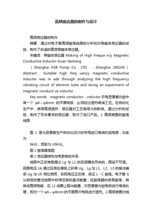
1 高频装置的振荡线路图1是为显像管生产自动化设计的专用进口烤消机组电路,功率为6kW,频率为10kHz。
图1 振荡器简图表1 感应器结构与电参数的关系线路中正反馈是通过Lg与L1的互感耦合而来的,固定不可调。
回路电压Uk通过互感在栅极上获得Ug,Lg与L1、L2、L3的接法确保Ug与Uk相位相同,实现电压正反馈,保证L-C振荡。
电子管G 从前级的整流线路中获得足够的直流能量,经振荡器的自激振荡,转换成高频电能,在L2线圈上输出能量,对显像管内腔电极进行烤消处理,即对一个φ6~φ8mm的平面圆片电极进行透热。
2 高频装置对线圈的匹配要求在并联谐振回路中,线圈分3部分,反馈线圈L1,工作线圈L2,保护线圈L3。
高频加热制作方法

高频加热制作方法
嘿,朋友们!今天咱就来讲讲高频加热制作方法,这可是个超有趣的玩意儿!
你想想啊,就像变魔术一样,能把一些材料变得热乎乎的,然后创造出各种神奇的东西来!比如说,你要打造一个精致的金属小物件,那高频加热就能派上大用场啦!
咱先来说说准备工作。
哎呀,这就好比要去打仗,得先把武器弹药准备好呀!你得有一台靠谱的高频加热设备,这可是关键的家伙。
然后呢,把你要加热的材料整整齐齐地摆好。
接着就是激动人心的加热过程啦!你开启设备,哇塞,就看着那能量在材料上奔走,就像一群小精灵在欢快地跳舞!这时候你就一边观察着,一边心里想着:“哇,这也太神奇了吧!”这不就跟你看着面包在烤箱里慢慢膨胀一样兴奋嘛!
“哎呀,会不会温度太高啦?” “放心啦,咱能控制好的嘛!”这时
候你可能会和旁边的小伙伴有这样的对话。
然后小心翼翼地调整着各种参数,确保一切都刚刚好。
等加热到合适的时候,嘿,奇迹就出现啦!材料变得软软的,或者达到了你想要的状态。
这感觉,真的太棒啦!就好像你努力了好久,终于达成了目标一样,那成就感,杠杠的!
高频加热制作方法,真的是既有趣又实用啊!它能让我们创造出好多好玩的、有用的东西。
还等什么呢?赶紧去试试吧!让我们都成为高频加热的小能手!。
高频加热感应线圈制作方法
高频加热感应线圈制作方法
高频加热感应线圈制作方法步骤如下:
1.设计感应线圈的结构和规格,包括线圈的形状、导体材料、线径、总匝数等参数。
2.选择合适的导线,将导线按照预定的匝数缠绕成线圈,注意保证匝间绝缘。
3.将线圈定位在合适的支架上,并用绝缘胶固定,保证线圈形状的稳定。
4.通过高频电源进行线圈的初次加热,并进行调整,以确保线圈的加热水平和功率的合适性。
5.进行质量控制,包括检查匝间绝缘情况、接头无误、线材无损等,确保线圈质量合适。
6.将加热线圈整体进行封装处理,保护线圈免受外界干扰,并便于加热器的使用和维护。
7.对线圈进行测试和放电处理,确保加热器的安全和稳定性。
8.进行性能评估,并记录相关数据和结果,为后续改进和优化提供参考。
自制简易高频感应加热

自制简易高频感应加热感应加热简介电磁感应加热,或简称感应加热,是加热导体材料比如金属材料的一种方法。
它主要用于金属热加工、热处理、焊接和熔化。
顾名思义,感应加热是利用电磁感应的方法使被加热的材料的内部产生电流,依靠这些涡流的能量达到加热目的。
感应加热系统的基本组成包括感应线圈,交流电源和工件。
根据加热对象不同,可以把线圈制作成不同的形状。
线圈和电源相连,电源为线圈提供交变电流,流过线圈的交变电流产生一个通过工件的交变磁场,该磁场使工件产生涡流来加热。
感应加热原理感应加热表面淬火是利用电磁感应原理,在工件表面层产生密度很高的感应电流,迅速加热至奥氏体状态,随后快速冷却得到马氏体组织的淬火方法,当感应圈中通过一定频率的交流电时,在其内外将产生与电流变化频率相同的交变磁场。
金属工件放入感应圈内,在磁场作用下,工件内就会产生与感应圈频率相同而方向相反的感应电流。
由于感应电流沿工件表面形成封闭回路,通常称为涡流。
此涡流将电能变成热能,将工件的表面迅速加热。
涡流主要分布于工件表面,工件内部几乎没有电流通过,这种现象称为表面效应或集肤效应。
感应加热就是利用集肤效应,依靠电流热效应把工件表面迅速加热到淬火温度的。
感应圈用紫铜管制做,内通冷却水。
当工件表面在感应圈内加热到一定温度时,立即喷水冷却,使表面层获得马氏体组织。
感应电动势的瞬时值为:式中:e——瞬时电势,V;Φ——零件上感应电流回路所包围面积的总磁通,Wb,其数值随感应器中的电流强度和零件材料的磁导率的增加而增大,并与零件和感应器之问的间隙有关。
为磁通变化率,其绝对值等于感应电势。
电流频率越高,磁通变化率越大,使感应电势P相应也就越大。
式中的负号表示感应电势的方向与的变化方向相反。
零件中感应出来的涡流的方向,在每一瞬时和感应器中的电流方向相反,涡流强度取决于感应电势及零件内涡流回路的电抗,可表示为:式中,I——涡流电流强度,A;Z——自感电抗,Ω;R——零件电阻,Ω;X——阻抗,Ω。
用微机改造高频感应加热设备

用微机改造高频感应加热设备高频感应加热设备主要由可控硅调压电路、升压变压器、高压整流器、电子管振荡器和降压变压器组成。
其原理框图示于图1。
图1 高频感应加热设备原理框图我国早期的高频感应加热设备普遍采用汞弧闸流管整流,对工作环境要求十分苛刻,容易产生阴弧,故障率高,工作效率低,现在的高频设备都采用交流可控硅调压器调压、升压整流,得到所需直流高压,以满足不同的加工工艺要求。
我厂热处理工段现有一台60kW、200~300kHz高频感应加热设备,系50年代仿苏产品,于1985年改造为可控硅调压,高压硅堆整流,但采用的是模拟式控制电路,存在着较多缺陷。
1 改造方案随着计算机技术的发展,单片微型计算机以其体积小、价格低、功能强在许多工业控制领域获得了越来越广泛的应用。
针对我厂高频设备的现状,进行整机更新是不现实的,不仅造成很大的浪费,而且存在资金和场地问题,因此只能走局部改造之路。
我们仅用了2万余元,便完成了设备改造任务,具有很高的经济和使用价值,是一条改造旧式高频设备的好路子。
具体改造方案如下:1.1 主电路主要将三相半控调压改为三相全控调压,如图2所示。
图2 主电路改造前后对照图(a)改造前(b)改造后主电路的其它部分也作了如下变动:(1)拆除主电路进线端的三相电源滤波器;(2)拆除用于门机械连锁的三相刀闸开关,改为行程开关电气连锁;(3)主电路三相输出端的电流互感器原用于常规继电器过流保护,现改为单片机控制一级过流保护;(4)升压变压器原边加3个RC吸收电路,副边也接有3个压敏保护电阻,以吸收变压器接通和断开时产生的浪涌电流;(5)改自制高压硅堆为高压硅整流桥,安装方便,可靠耐用。
1.2 控制电路主要把原模拟式控制电路改为单片机控制电路,控制主板采用某厂研制的脉冲形成及过流保护印刷线路板和工作电源及脉冲功放印刷线路板,具体包括以下5个组成部分:(1)同步电路:用来使触发脉冲与系统的电压保护严格的相位关系,从而使可控硅的导通角相同,以保证主电路可靠地工作,其原理框图如图3所示。
磁铁加热器制作方法

磁铁加热器制作方法步骤1:准备材料和工具1.1:准备一个铁座,用于安装磁铁和加热材料。
1.2:准备两块强力磁铁。
1.3:准备一个加热材料,例如铁块或石墨棒。
1.4:准备一把火柴或打火机作为点火工具。
1.5:准备一块保护板和一块隔热材料。
步骤2:制作磁铁装置2.1:将铁座放在平整的工作台上。
2.2:将两块强力磁铁叠放在一起,确保磁性相同的两面朝向外侧。
2.3:用胶水或胶带将两块磁铁固定在铁座上。
步骤3:安装加热材料3.1:将加热材料放在磁铁之间的缝隙中。
确保加热材料与磁铁接触紧密,以便热量传导更好。
3.2:用保护板将加热材料覆盖起来,以防止飞溅和伤害。
步骤4:点火和加热4.1:用火柴或打火机点燃加热材料。
4.2:当加热材料开始发热时,用隔热材料将磁铁加热器包裹住,以保持热量。
4.3:等待一段时间,使加热材料足够热,以供你所需要的应用。
步骤5:注意事项5.1:在制作和使用磁铁加热器时,务必注意安全。
加热材料会变得非常热,避免直接接触和烫伤。
5.2:加热器会产生烟雾和有害气体,请确保在通风良好的地方使用,并避免长时间暴露于这些气体中。
5.3:在使用加热器时,尽量避免将其放置在易燃物附近,以防引起火灾。
总结:以上是一个简单的磁铁加热器制作方法。
请记住,在制作和使用任何自制加热设备时,始终要注意安全。
使用时要小心,以免烫伤或引发其他意外。
如果你对自己的制作能力没有信心,最好购买专业制造的加热设备,以确保安全和有效的加热效果。
高频电感制作方法

DR 型铁 芯 线 圈 因 铁 芯 外 型 尺 寸 、 绕 线 所 用 铜 线 的 多 样 性,决定了此种线圈电感量分布的 广 泛 性 。 从 l uH 到 10 mH 甚至更高的电感量均可由 DR 型铁芯设计形成, 且可大批量 生产。供应厂家研制出一系列的规格品可供挑选,同时也可按 具体要求设计制造。
UU 型线架(bobbin)有 PBT 和电木两种材质,其结构常见 有双槽和四槽两种,每槽(双槽型)或每两槽(四槽型)各绕一
附图 变压器线圈剖面圈
4.1 绕 线 附图为成型变压器线包剖面图, 图中出示了各层线圈所
用铜线线径、并绕根数、圈数、挡 墙 宽 度 及 (下转第 86 页)
76
胡正阳 胡昌权 // 对益阳市小型水库工程安全管理的思考
SDR 型 铁 芯 (镀 银 铁 芯 )与 DR 型 铁 芯 的 区 别 是 :SDR 型 铁芯一端有两 个 镀 银 半 面 代 替 DR 型 铁 芯 的 两 个 PIN, 因 铁 芯直径一般大于其长度,槽宽较窄,绕线时一般不考虑其排列 的整齐性, 故提高 SDR 型 铁芯线圈耐电流性的另一方法是: 增加铜线并绕根数(一般为两根)。 该产品焊锡时先用高温焊
感应加热器制作方法

感应加热器制作方法
感应加热器是一种利用电磁感应原理加热物体的装置。
它可以在没有直接接触或导电接触的情况下加热物体,因此具有广泛的应用领域,如工业加热、烹饪、医疗等。
制作一个简单的感应加热器需要以下步骤:
1. 准备材料:
- 磁性铁芯
- 铜线
- 电源线
- 开关
- 散热器
2. 制作线圈:
将铜线绕在磁性铁芯上,制作一个线圈。
线圈的大小和圈数可以根据需要进行调整。
确保线圈的每一圈都紧密相连,没有空隙。
3. 连接电源线:
将电源线与线圈的两端连接起来,通过焊接或其它方法进行固定。
确保连接牢固并正确接触,以保证电流正常流动。
4. 安装开关:
在电源线上安装一个开关,用于控制电流的通断。
确保开关的质量可靠,并使其易于操作。
5. 安装散热器:
将散热器安装在磁性铁芯的周围,用于散热和保护装置。
选择合适的散热器以确保加热器的稳定工作和长寿命。
完成上述步骤后,感应加热器的制作就完成了。
当通电时,电流经过线圈会产生磁场,磁场会感应铁芯中的涡流。
涡流会产生热量,从而加热了对应的物体。
在使用感应加热器时,要注意安全,避免触摸线圈和高温物体。
总结一下,感应加热器制作的关键是制作合适的线圈和连接电源线。
正确操作和注意安全性可以确保加热器的有效工作。
随着技术的不断发展,感应加热器将会在各个领域得到更广泛的应用和进一步的改进。
5千瓦电磁感应加热炉制作方法

5千瓦电磁感应加热炉制作方法全文共四篇示例,供读者参考第一篇示例:5千瓦电磁感应加热炉是一种高效、节能、环保的加热设备,广泛应用于工业生产中。
下面我们就来介绍一下5千瓦电磁感应加热炉的制作方法。
一、设备准备1. 磁感应加热炉主机:选择功率为5千瓦的电磁感应加热炉主机,确保加热效率和加热温度的稳定性。
2. 冷却系统:准备水冷却系统,确保设备在工作过程中的散热效果。
3. 控制系统:选购合适的控制系统,用于调节加热炉的加热功率和温度。
4. 冷却水泵和水箱:保证设备的冷却系统正常运作。
5. 电源线和接头:选择合适的电源线和接头,并确保电路连接正确。
二、组装设备1. 将磁感应加热炉主机安装在平整的地面上,确保设备稳固。
4. 启动设备,调节控制系统,确认设备功能正常。
三、使用方法1. 将需要加热的工件放置在加热炉内。
2. 根据工件的材质和加热要求,调节加热功率和温度。
3. 启动加热炉,待工件达到预定温度后关闭加热炉。
4. 取出加热后的工件,进行下一步处理。
四、注意事项1. 在使用加热炉时,应注意设备周围的安全防护,避免发生意外事故。
3. 定期检查加热炉的运行状态,保持设备的正常工作。
4. 使用加热炉时应遵守相关规定,确保设备的安全运行。
通过以上的介绍,相信大家对5千瓦电磁感应加热炉的制作方法有了更深入的了解。
希望这份文章对大家在工业生产中使用电磁感应加热炉有所帮助。
祝大家工作顺利,生产高效!第二篇示例:5千瓦电磁感应加热炉是一种常用的工业加热设备,主要用于加热金属材料,加工成型等工艺。
它的原理是利用电磁感应原理,通过感应加热的方式将金属材料加热至所需温度,从而实现加工成型目的。
今天我们将介绍一下5千瓦电磁感应加热炉的制作方法,帮助那些对此感兴趣的朋友们了解这一工艺的过程。
我们需要准备以下材料和工具:1台5千瓦电磁感应加热炉主机、金属容器、电源线、控制面板、感应线圈等。
接下来,我们开始制作5千瓦电磁感应加热炉。
老外自制的中频感应加热装置

DIY中频加热炉IntroductionInduction heating is a non-contact heating process. It uses highfrequency electricity to heat mat erials that are electricallyconductive. Since it is non-contact, the heating process does notcont aminate the material being heated. It is also very efficient sincethe heat is actually generated inside the workpiece. This can becontrasted with other heating methods where heat is generated in aflame or heating element, which is then applied to the workpiece. Forthese reasons Induction He ating lends itself to some uniqueapplications in industry.How does Induction Heating work ?A source of high frequency electricity is used to drive a largealternating current through a coil. This coil is known as the workcoil. See the picture opposite.The passage of current through this coil generates a very intenseand rapidly changing magnetic fi eld in the space within the work coil.The workpiece to be heated is placed within this intense al ternatingmagnetic field.Depending on the nature of the workpiece material, a number of things happen...The alternating magnetic field induces a current flow in theconductive workpiece. The arrangement of the work coil and theworkpiece can be thought of as an electrical transformer. The work coili s like the primary where electrical energy is fed in, and theworkpiece is like a single turn seco ndary that is short-circuited. Thiscauses tremendous currents to flow through the workpiece. Thes e areknown as eddy currents.In addition to this, the high frequency used in induction heatingapplications gives rise to a phe nomenon called skin effect. This skineffect forces the alternating current to flow in a thin laye r towardsthe surface of the workpiece. The skin effect increases the effectiveresistance of the m etal to the passage of the large current. Thereforeit greatly increases the heating effect caused by the current inducedin the workpiece.(Although the heating due to eddy currents is desirable inthis application, it is interesting to note that transformermanufacturers go to great lengths to avoid this phenomenon in theirtransform ers. Laminated transformer cores, powdered iron cores andferrites are all used to prevent eddy cu rrents from flowing insidetransformer cores. Inside a transformer the passage of eddy currents is highly undesirable because it causes heating of the magnetic core andrepresents power that is was ted.)And for Ferrous metals ?For ferrous metals like iron and some types of steel, there is anadditional heating mechanism tha t takes place at the same time as theeddy currents mentioned above. The intense alternating magne tic fieldinside the work coil repeatedly magnetises and de-magnetises the ironcrystals. This rapi d flipping of the magnetic domains causesconsiderable friction and heating inside the material. H eating due tothis mechanism is known as Hysteresis loss, and is greatest formaterials that have a large area inside their B-H curve. This can be alarge contributing factor to the heat generated during inductionheating, but only takes place inside ferrous materials. For this reasonferrous ma terials lend themselves more easily to heating by inductionthan non-ferrous materials.It is interesting to note that steel looses its magnetic materialswhen heated above approximately 700°C. This temperature is known as theCurie temperature. This means that above 700°C there ca n be no heatingof the material due to hysteresis losses. Any further heating of thematerial must be due to induced eddy currents alone. This makes heatingsteel above 700°C more of a challenge f or the induction heatingsystems. The fact that copper and Aluminium are both non-magnetic andvery good electrical conductors, can also make these materials achallenge to heat efficiently. (We wi ll see that the best course ofaction for these materials is to up the frequency to exaggerate los sesdue to the skin effect.)What is Induction Heating used for ?Induction heating can be used for any application where we want toheat an electrically conductive material in a clean, efficient andcontrolled manner.One of the most common applications is for sealing the anti-tamperseals that are stuck to the top of medicine and drinks bottles. A foilseal coated with "hot-melt glue" is inserted into the plas tic cap andscrewed onto the top of each bottle during manufacture. These foilseals are then rapid ly heated as the bottles pass under an inductionheater on the production line. The heat generated melts the glue andseals the foil onto the top of the bottle. When the cap is removed, thefoil re mains providing an airtight seal and preventing any tampering orcontamination of the bottle's con tents until the customer pierces thefoil.Another common application is "getter firing" to removecontamination from evacuated tubes such as TV picture tubes, vacuumtubes, and various gas discharge lamps. A ring of conductive materialcal led a "getter" is placed inside the evacuated glass vessel. Sinceinduction heating is a non-conta ct process it can be used to heat thegetter that is already sealed inside a vessel. An induction work coilis located close to the getter on the outside of the vacuum tube andthe AC source is tur ned on. Within seconds of starting the inductionheater, the getter is heated white hot, and chemi cals in its coatingreact with any gasses in the vacuum. The result is that the getterabsorbs any last remaining traces of gas inside the vacuum tube andincreases the purity of the vacuum.Yet another common application for induction heating is a processcalled Zone purification used in the semiconductor manufacturingindustry. This is a process in which silicon is purified by means of amoving zone of molten material. An Internet Search is sure to turn upmore details on this pr ocess that I know little about.Other applications include melting, welding and brazing or metals.Induction cooking hobs and ricecookers. Metal hardening of ammunition,gear teeth, saw blades and drive shafts, etc are also com monapplications because the induction process heats the surface of themetal very rapidly. Therefo re it can be used for surface hardening, andhardening of localised areas of metallic parts by "ou trunning" thethermal conduction of heat deeper into the part or to surroundingareas. The non cont act nature of induction heating also means that itcan be used to sterilise metal instruments by h eating them to hightemperatures whilst they are already sealed inside a known sterileenvironment in order to kill germs.What is required for Induction Heating ?In theory only 3 things are essential to implement induction heating:1. A source of High Frequency electrical power,2. A work coil to generate the alternating magnetic field,3.An electrically conductive workpiece to be heated,Having said this, practical induction heating systems are usually alittle more complex. For examp le, a matching network is often requiredbetween the High Frequency source and the work coil in or der to getgood power transfer. Water cooling systems are also common in highpower induction heate rs to remove waste heat from the work coil and itsmatching network. Finally some control electron ics is usually employedto control the intensity of the heating action, ensure consistentresults, and to protect the system from adverse operating conditions.However, the basic principle of opera tion of any induction heaterremains the same as described earlier.Practical implementationIn practice the work coil is usually incorporated into a resonanttank circuit. This has a number of advantages. Firstly, it makes eitherthe current or the voltage become sinusoidal. This minimis es losses inthe inverter by allowing it to benefit from eitherzero-voltage-switching or zero-curr ent-switching depending on the exactarrangement chosen. The sinusoidal waveform at the work coil alsorepresents a more pure signal and causes less Radio FrequencyInterference to nearby equipment. We will see that there are a numberof resonant schemes that the designer of an induction heater can choosefor the work coil:Series resonant tank circuitThe work coil is made to resonate at the intended operatingfrequency by means of a capacitor plac ed in series with it. This causesthe current through the work coil to be sinusoidal. The seriesre sonance also magnifies the voltage across the work coil, far higherthan the output voltage of the inverter alone. The inverter sees asinusoidal load current but it must carry the full current th at flowsin the work coil. For this reason the work coil often consists of manyturns of wire with only a few amps or tens of amps flowing.This arrangement is commonly used in things like rice cookers wherethe power level is low, and th e inverter is located next to the objectto be heated. The main drawbacks of the series resonant a rrangement arethat the inverter must carry the same current that flows in the workcoil. In additi on to this the series resonant action can become verypronounced if there is no workpiece presentto damp the circuit. Thisis not a problem in applications like rice cookers where the workpieceis always the same cooking vessel, and its properties are well known atthe time of design.The tank capacitor is typically rated for a high voltage because ofthe resonant voltage rise expe rienced in the series tuned resonantcircuit.Parallel resonant tank circuitThe work coil is made to resonate at the intended operatingfrequency by means of a capacitor plac ed in parallel with it. Thiscauses the current through the work coil to be sinusoidal. The parall elresonance also magnifies the current through the work coil, far higherthan the current capabili ty of the inverter alone. The inverter sees asinusoidal load current. However, in this case it on ly has to carry thepart of the load current that actually does real work. The inverterdoes not ha ve to carry the full circulating current in the work coil.This means that the work coil can be pl aced at a location remote fromthe inverter without incurring massive losses in the feed wires.It also means that work coils using this technique often consist offew turns of a thick copper co nductor but with large currents of manytens or hundreds of amps flowing. (This is necessary to ge t therequired Ampere turns to do the induction heating.) Water cooling iscommon for all but the s mallest of systems. This is needed to removeexcess heat generated by the passage of the large hig h frequencycurrent through the work coil and its associated tank capacitor.In the parallel resonant tank circuit the work coil can be thoughtof as an inductive load with a "power factor correction" capacitorinstalled across it. The PFC capacitor provides reactive curre nt flowequal and opposite to the inductive current drawn by the work coil.Therefore the only curr ent flow from the inverter is a small amountrequired to overcome losses in the "PFC" capacitor an d the work coil.There is always some loss in this tank circuit due to dielectric lossin the capac itor and skin effect causing resistive losses in the workcoil. Therefore a small current is alway s drawn from the inverter. Whena lossy workpiece is inserted into the work coil, this damps thepa rallel resonant circuit by introducing a further loss into thesystem. Therefore the current drawn by the parallel resonant tankcircuit increases when a workpiece is entered into the coil.Impedance matchingOr simply "Matching". This refers to the electronics that sitsbetween the source of high frequenc y power and the work coil we areusing for heating. In order to heat a solid piece of metal viaind uction heating we need to cause a TREMENDOUS current to flowin the surface of the metal. However this can be contrasted with theinverter that generates the high frequency power. The invertergene rally works better (and the design is somewhat easier) if itoperates at fairly high voltage but a low current. This allows commonswitch mode MOSFETs to be used. The comparatively low currents al somake the inverter less sensitive to layout and stray inductance. It isthe job of the matching n etwork and the work coil to transform the highvoltage/low current from the inverter to the low vo ltage/high currentrequired to heat the workpiece efficiently.We can think of the tank circuit incorporating the work coil (Lw) and its capacitor (Cw) as a parallel resonant circuit.This has a resistance (R) due to the lossy workpiece coupled intothe work coil due to the magneti c coupling between the two conductors.See the schematic opposite.In practice the resistance of the work coil, the resistance of thetank capacitor, and the resista nce of the workpiece all introduce aloss into the tank circuit and damp the resonance. Therefore it isuseful to combine all of these losses into a single "loss resistance."In the case of a paral lel resonant circuit this loss resistance appearsdirectly across the tank circuit. This resistanc e represents the onlycomponent that can consume power, and therefore we can think of thisloss res istance as the load that we are trying to drive power into asefficiently as possible.When driven at resonance the current drawn by the tank capacitor andthe work coil are equal and o pposite in phase and therefore cancel eachother out as far as the source of power is concerned. T his meansthat the only load presented to the power source at the resonantfrequency is the loss re sistance across the tank circuit.(Notethat, when driven either side of the resonant frequency, t here is anadditional "out-of-phase" component to the current caused by incompletecancellation of the work coil current and the tank cap current. Thisreactive current increases the total magnitud e of the current beingdrawn from the source but does not contribute to any useful heating inthe w orkpiece.)The job of the matching network is simply to transform thisrelatively large loss resistance acros s the tank circuit down to alower value that better suits the inverter attempting to drive it.The re are many different ways to achieve this impedance transformationincluding tapping the work coil, using a ferrite transformer, acapacitive divider in place of the tank capacitor, or a matching circuit such as an L-match network.In the case of an L-match network it can transform the relativelyhigh load resistance of the tank circuit down to something around 10ohms which better suits the inverter. This figure allows the inverterto run from several hundred volts whilst keeping currents down to areasonable level so th at standard switch-mode MOSFETs can be used toperform the switching operation.The L-match network consists of components Lm and Cm shown opposite.The L-match network also has another highly desirable property. TheL-match network provides a pro gressively rising inductive reactance toall frequencies higher than the resonant frequency of the tank circuit.This is very important when the work coil is to be fed from an inverterthat generat es a squarewave voltage output. Here is an explanation ofwhy this is so…The squarewave voltage generated by most half-bridge and full-bridgecircuits is rich in high freq uency harmonics as well as the wantedfundamental frequency. Direct connection of such a voltage s ource to aparallel resonant circuit would cause excessive currents to flow at theharmonics of the drive frequency! This is because the tank capacitor inthe parallel resonant circuit presents a p rogressively lower capacitivereactance to increasing frequencies. This is potentially very damagi ngto a voltage-source inverter. It results in large current spikes at theswitching transitions as the inverter tries to rapidly charge anddischarge the tank capacitor on rising and falling edges of thesquarewave. The inclusion of the L-match network between the inverterand the tank circuit negates this problem. Now the output of theinverter sees the inductive reactance of Lm in the mat ching networkfirst, and all harmonics see a gradually rising inductive impedance.In summary, the inclusion of an L-match network between the inverter and the parallel resonant ta nk circuit achieves two things.1.Impedance matching so that the required amount of power can be supplied from the inverter to the workpiece,2.Presentation of a rising inductive reactance to high frequency harmonics to keep the inverter safe and happy.Looking at the previous schematic above we can see that thecapacitor in the matching network (Cm) and the tank capacitor (Cw) areboth in parallel. In practice both of these functions are usuallyaccomplished by a single capacitor. Most of its capacitance can bethought of as being in parallel resonance with the work coil, with asmall amount providing the impedance matching action with the matchinginductor (Lm.) Combing these two capacitances into one leads us toarrive at the LCLR model for the work coil arrangement, which iscommonly used in industry.The LCLR work coilThis arrangement incorporates the work coil into a parallel resonantcircuit and uses the L-match network between the tank circuit and theinverter. The matching network is used to make the tank circuit appearas a more suitable load to the inverter, and its derivation isdiscussed in the section above.The LCLR work coil has a number of desirable properties:1. A huge current flows in the work coil, but the inverter only has tosupply a low current. The large circulating current is confined to thework coil and its parallel capacitor, which are usually located closeto each other.2.Only low current flows along the transmission line from the inverter to the tank circuit, so this can use lighter duty cable.3.Any stray inductance of the transmission line becomes part of the matching network inductance (Lm.)4.The inverter sees a sinusoidal load current so it can benefit fromZCS or ZVS to reduce its switching losses and therefore run cooler.5.The series matching inductor can be altered to cater for different loads placed inside thework coil.6.The tank circuit can be fed via several matching inductors frommany inverters to reach power levels above those achievable with asingle inverter. The matching inductors provide inherent sharing of theload current between the inverters and also make the system tolerant tosome mismatching in the switching instants of the paralleled inverters.Another advantage of the LCLR work coil arrangement is that it doesnot require a high-frequency transformer to provide the impedancematching function. Ferrite transformers capable of handling severalkilowatts are large, heavy and quite expensive. In addition to this,the transformer must be cooled to remove excess heat generated by thehigh currents flowing in its conductor. The incorporation of theL-match network into the LCLR work coil arrangement removes thenecessity of a transformer to match the inverter to the work coil,saving cost and simplifying the design.However, the designer should appreciate that a 1:1 isolatingtransformer may still be required between the inverter and the input tothe LCLR work coil arrangement if electrical isolation is necessaryfrom the mains supply. It depends whether isolation is important, andwhether the PSU in the induction heater already provides sufficientelectrical isolation to meet these requirements.Complete schematicThe complete schematic showing the inverter driving its LCLR work coil arrangement is shown belo w.Note that this schematic DOES NOT SHOW the MOSFET gate-drive and control electronics! Please dont ask for further information.The inverter is a simple half-bridge consisting of two MTW14N50MOSFETs made my On-semiconductor (formerly Motorola.) It is fed from asmoothed DC supply with decoupling capacitor across the rails tosupport the AC current demands of the inverter. However, it should berealised that the quality and regulation of the power supply forinduction heating applications is not critical. Full-wave rectified(un-smoothed) mains can work equally as well as smoothed and regulatedDC when it comes to heating metal. And there are many arguments forkeeping the size of the DC bus capacitor down to a minimum. Inparticular it improves the power factor of current drawn from the mainsupply, and it also minimises stored energy in case of fault conditionswithin the inverter.The DC blocking capacitor is merely to block the DC output from thehalf-bridge inverter from causing current flow through the work coil.It is sized sufficiently large that it does not take part in theimpedance matching, and does not adversely effect the operation of theLCLR work coil arrangement.Fault toleranceThe LCLR work coil arrangement is very well behaved under a variety of possible fault conditions.1.Open circuit work coil.2.Short circuit work coil, (or tank capacitor.)3.Shorted turn in work coil.4.Open circuit tank capacitor.All of these failures result in an increase in the impedance beingpresented to the inverter and therefore a corresponding drop in thecurrent drawn from the inverter. The author has personally used ascrewdriver to short-circuit between turns of a work coil carryingseveral hundred amps. Despite sparks flying at the location of theapplied short-circuit, the load on the inverter is reduced and thesystem survives this treatment with ease.The worst thing that can happen is that the tank circuit becomesdetuned such that its natural resonant frequency is just above theoperating frequency of the inverter. Since the drive frequency is stillclose to resonance there is still significant current flow out of theinverter. But the power factor is reduced due to the detuning, and thecurrent begins to lead the voltage. This situation is undesirablebecause the load current seen by the inverter changes direction beforethe applied voltage changes sign. The outcome of this is that currentis force-commutated between free-wheel diodes and the opposing MOSFETevery time the MOSFET is turned on. This causes a forced reverserecovery of the free-wheel diodes whilst they are carrying significantforward current. This results in a large current surge through both thediode and the opposing MOSFET that is turning on.Whilst not a problem for special fast recovery rectifiers, thisforced recovery can cause problems if the MOSFETs intrinsic body diodesare used to provide the free-wheel diode function. However, it should be realised that proper control of the inverter operating frequency should ensure that it tracks the resonant frequency of the tankcircuit. Therefore the leading power factor condition should ideally not arise, and should certainly not persist for any length of time. The resonant frequency should be tracked up to its limit, then the system shut-down if it has wandered outside of an acceptable range. Power control methodsIt is often desirable to control the amount of power processed by an induction heater. This determines the rate at which heat energy is transferred to the workpiece. The power setting of this type of induction heater can be controlled in a number of different ways:1. Varying the DC link voltage.The power processed by the inverter can be decreased by reducing the supply voltage to the inverter. This can be done by running theinverter from a variable voltage DC supply such as a controlledrectifier using thyristors to vary the DC supply voltage derived from the mains supply. The impedance presented to the inverter is largely constant with varying power level, so the power throughput of the inverter is roughly proportional to the square of the supply voltage. Varying the DC link voltage allows full control of the power from 0% to 100%.2. Varying the duty ratio of the devices in the inverter.The power processed by the inverter can be decreased by reducing theon-time of the switches in the inverter. Power is only sourced to the work coil in the time that the devices are switched on. The load current is left to freewheel through the devices body diodes during the deadtime when both devices are turned off. Varying the duty ratio of the switches allows full control of the power from 0% to 100%. The only significant drawback is forced reverse recovery of the free-wheel diodes that can occur when the duty ratio is reduced.3. Varying the operating frequency of the inverter.The power supplied by the inverter to the work coil can be reducedby detuning the inverter from the natural resonant frequency of the tank circuit incorporating the work coil. As the operating frequency of the inverter is moved away from the resonant frquency of the tank circuit, there is less resonant rise in the tank circuit, and the current in the work coil diminishes. Therefore less circulating current is induced in the workpiece.In order to control the power the inverter is normally detuned onthe high frequency side of the tank circuits natural resonance. This causes the inductive reactance of the matching circuit to become dominant as the frequency increases. Therefore the current drawn from the inverter by the matching network starts to lag in phase and diminish in amplitude. Both of these factors contribute to a reduction in real power throughput. In addition to this the lagging power factor ensures that the devices in the inverter still turn on with zero voltage across them.This method of controlling power level by detuning is very simplesince most induction heaters already have control over the operating frequency of the inverter in order to cater for different workpieces and work coils. The downside is that it only provides a limited range of control, as there is a limit to how fast power semiconductors can be made to switch. This is particularly true in high power applications where the devices may be running close to maximum switching speeds anyway.4. Varying the value of the inductor in the matching network.The power supplied by the inverter to the work coil can be varied by altering the value of the matching network components. The L-match network between the inverter and the tank circuit technically consists of an inductive and a capacitive part. But the capacitive part is in parallel with the work coil's own tank capacitor, and in practice these are usually one and the same part. Therefore the only part of the matching network that is available to make adjustable is the inductor.The matching network is responsible for transforming the load of the workcoil to a suitable load impedance to be driven by the inverter. Altering the inductance of the matching inductor adjusts the value to which the load impedance is translated. In general, decreasing the inductance of the matching inductor causes the work coil impedance to be transformed down to a lower impedance. This lower load impedance being presented to the inverter causes more power to be sourced from the inverter. Conversely, increasing the inductance of the matching inductor causes a higher load impedance to be presented to the inverter. This lighter load results in a lower power flow.The degree of power control achieveable by altering the matching inductor is fairly small. There is a also a shift in the resonant frequency of the overall system. This is the price to pay for combining the L-match capacitance and tank capacitance into one unit. The L-matchnetwork essentially borrows some of the capacitance from the tank capacitor to perform the matching operation, thus leaving the tank circuit to resonate at a higher frequency. For this reason the matching inductor is usually fixed or adjusted in coarse steps to suit the intended workpiece to be heated, rather than provide the user with a fully adjustable power setting.Heating pictures。
小功率高频感应加热器的设计与制作
小功率高频感应加热器的设计与制作小功率高频感应加热器的设计与制作家用感应加热装置的典型应用是电磁灶,其功率一般在lkW左右,要求被加热容器的底部直径不小于120mm.本设计的感虚加热器输出功率定在200W~300W,感应器有效直径lOOmm 左右,主要用于小容量的液体、食品、易拉罐饮品的加热,在家庭、医院、宾馆房间、零售商店中有广泛应用.感应加热要求感应线圈的品质因数(Q值)高,Q可由下式计算:Q=X/R=ωL/R 其中,L 是感应线圈的电感(单位H),ω 是驱动源的开关频率,R 是感应线圈的等效串联电阻(Ω).通过以不同的驱动频率驱动加热线圈,可以得到线圈参数与频率的关系.当感应线圈靠近铁制品时.其等效电阻将大幅度增加,Q 值下降;而当其靠近非铁磁性金属时,其等效电阻增加很少,其Q 值下降不大.这种特性使铁金属更易被感应加热.例如,在驱动频率为100kHz 时,靠近铁制品的线圈,其R 值为2Ω,而靠近铝制品时,R 值仪0.238Ω;当驱动频率为400kHz 时,空载线圈的Q 值达到318,在靠近铝制品时下降为124,而在靠近铁制品时下降至13.因此,在选择驱动源频率时,要选择空载线圈的R 值和有铁金属时的R 值相差大的频率,这个频率范围一般在lOOkHz 至400kHz.为了减小加热线圈自身的损耗,线圈需用很多股细铜线组成的绞合线来绕制,这样容易制战高频损失小、Q值高的线圈.感应线圈有两种形状,一种是加热普通平底铁金属容器的平板线圈.另一种是加热易拉罐的筒形线圈.在实际的感应加热电路中,感应线圈与其等效串联阻抗R,以及外加电容器C 等共同构成LCR 串联谐振电路.图1 是本高频感应加热器的方框图.采用绝缘栅场效应管的半桥驱动、LC 串联谐振电路,用锁相环(PLL)和脉宽调制(PWM)电路作闭环控制,以保证串联谐振频率的稳定:用半桥功率电路驱动加热线圈.半桥输出电路输出阻抗低,即使用方波信号作电压驱动,输出电流波形也是正弦波,因而电压相电流的相位差小,功率传输效率高.整机电路见图2.PLL 及PWM 恒流控制电路:采用开关稳压集成电路UC3825,实际开关频率可达lMHz,具有两路大电流推挽式输出电路.利用UC3825 内的振荡电路构成压控振荡器VCO,其频率范围可取为200kHz~300kHz,由定时阻容元件R10+R9//Rt 和C5 的值决定.动态电阻Rt 由小信号MOSFET 管构成,其阻值受MCl4060B 的输出控制.考虑到加热线圈L 的电感量及串联谐振电容量的自由度,这个频率的可变化范围应有两倍左右.当取图2中的数值时,振荡频率约160kHz~380kHz.为了保证振荡频率的稳定,采用PLL 电路MCl4046B 作相位检测器.由电流互感器CT 检测出通过加热线圈L 的电流,CT 次级的负载Rl 取200Ω,转换,比为1V/1A,经D1、D2 双向限幅.Cl 耦合至ICl 的PCa 端;ICl 的PCb 端输入电压由IC2 的PWM 输出电压分压.得到,其值约5Vpeak,以满足CMOS 电平的需要.由于流过加热线圈的电流有少许滞后,故在PCb 端加入容量约1000pF 的相位补偿电容器C2.如果工作频率和LC 参数有变化, 该电容量也应梢应变化. 如f=300kHz 、电流相位滞后45. 时.相位补偿电容:Ccomp=1/2πRf=l/6.28x500x300xl03=1061pF如果以某一频率驱动加热线圈,当接近铝制时,由于LCR串联谐振电路的阻抗很低,通过的大电流可能会损坏MOSFET;如果空载,也可能造成桐同后果.因此必须采用恒流控制.这里,利用电流互感器CT 的输出经D3、D4 倍压整流届作为反馈信号,输出电流的调节用脉宽调制方式控制平均电流,由IC2 内部的误差放大器来实现.由IC2 内部的基准电压源经电阻分压后取得+2.5V 的电压,作为比较器的基准电压.调节W1 可改变输出电流,也可调节输出功率.MOSFET 驱动电路、半桥输出电路及LC 串联谐振电路:在负荷为铁制品时,由于串联谐振电路的R 将增大,故应设置较高的电源电腥(选定为300V).又由于在空载时,R 很小而Q 值高.将有很大的电流流过功率输出管,故应选用漏极电流大的MOSFET 管.这里选用电流达12A 的2SKl489 两强构成半桥输出.驱动信号由UC3825 输出、经C13~CJ6 和脉冲变压器Tl、T2 耦合至推动级.D7~D10 用于保护大功率MOSFET.在半桥输出电路中插入了电流互感器CT,用以检出流过加热线圈的电流.加热线圈L 和电容C19、C20 构成LC 谐振电路.作为半桥输出的负载.当LC 串联电路谐振时,即使用方波驱动,流过线圈的电流波形也是正弦波.加热线圈可作为平板形(加热甲底容器)或筒形(加热易拉.罐).为减少由于集肤效应产生高频损失,加热线圈的材料用120 根φ0.08mm 的细铜线绞合而成.线圈的尺寸见图3.整机供电电路:功率输出电路由交流市电经桥式整流提供+300V 电源,用7812 和78L05 提供+12V 及+5V给其余电路供电.+300V 电源在开机时会有大的冲击电流,因而滤波电容不能用电解电容,而要选薄膜电容器;C24 为4.71μF,另在半桥输出的电源端子加4.7μF(C21),使滤波电容的总容最为9.4μF.为避免半桥输出电路产生的噪声串人交流供电线路,加入了电感L2 作滤波器.元件选用:D1l、D13、D7、D9 采用肖特基二级管,D8、D10 采用超高速二极管;电感Ll、L2 及电流互感器CT 均采用磁环绕制.试用效果:由WI 设定功率为250W,此时交流电流约1.2A.对盛水的平底铁制容器,用平板线圈加热到水温80℃耗时200 秒;当不盛水时,加热至100℃仅用加40 秒;当用筒形线圈加热盛满水的铁罐头盒时,加热至80℃耗时180 秒.。
自制高频磁感应线圈的原理
自制高频磁感应线圈的原理
高频磁感应线圈的原理是利用高频电流在线圈内产生交变电磁场。
具体原理如下:
1. 根据法拉第电磁感应定律,当磁场穿过一个导体线圈时,会在线圈内产生感应电流。
2. 高频磁感应线圈一般由导体线圈和高频信号源组成。
高频信号源会提供高频交变电流,通常频率达到几十kHz至几百MHz。
3. 高频交变电流通过导体线圈时,会在线圈内产生交变的磁场。
4. 交变的磁场会引起线圈内感应电流的产生,这些感应电流会进一步产生磁场。
5. 在线圈的中心或附近产生的磁场可以用于多种应用,如无线充电、电磁感应加热等。
总之,高频磁感应线圈利用高频电流在线圈内产生交变磁场,进而引起感应电流和进一步的磁场产生。
这种原理被广泛应用于无线通信、无线充电、电磁感应加热等领域。
加热感应器的制作与焊接
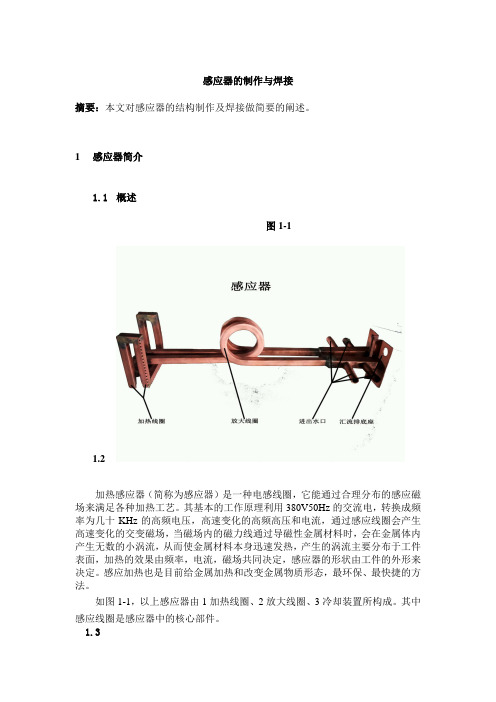
感应器的制作与焊接摘要:本文对感应器的结构制作及焊接做简要的阐述。
1感应器简介1.1概述图1-11.2加热感应器(简称为感应器)是一种电感线圈,它能通过合理分布的感应磁场来满足各种加热工艺。
其基本的工作原理利用380V50Hz的交流电,转换成频率为几十KHz的高频电压,高速变化的高频高压和电流,通过感应线圈会产生高速变化的交变磁场,当磁场内的磁力线通过导磁性金属材料时,会在金属体内产生无数的小涡流,从而使金属材料本身迅速发热,产生的涡流主要分布于工件表面,加热的效果由频率,电流,磁场共同决定,感应器的形状由工件的外形来决定。
感应加热也是目前给金属加热和改变金属物质形态,最环保、最快捷的方法。
如图1-1,以上感应器由1加热线圈、2放大线圈、3冷却装置所构成。
其中感应线圈是感应器中的核心部件。
1.3感应线圈的结构及类型感应器结构包括加热线圈、汇流排和进出水口构成。
下面是几种常用感应器外形。
图1-2 典型感应线圈的结构(a)多匝单线圈(b)单匝单线圈(c)单匝多线圈(d)多匝多线圈图1-3 用来加热各种形状部件的多匝线圈结构2感应器的制作1.2.1圆形铜管感应器的制作步骤图2-11.制作前阅览工艺图纸,仔细查看工艺要求和关键部位必须按图作业。
2.找到图纸上标注的管料规格,测量模具的尺寸进行下料。
3.将下好的管料在工作平台校直,不能有弯曲变形,要保证管料的规格。
4.缠绕线圈前在管料上缠好玻璃丝胶带,缠绕胶带时把握好密度均匀。
5.缠绕线圈时,将管料放相应在模具上,用左手固定好开端,再用右手,开始按所需的方向进行缠绕,缠绕时用力均匀,思路明确,按图所需要的圈数进行制作。
6.线圈绕好后,将汇流排调整为横向水平位置,一般汇流排间隙为25mm左右。
7.制作外通水的进出水,用弯管器把管料折弯成90°左右即可,再用电钻去掉管口内毛刺。
(注:如制作内通水的进出水时,下料时保证管料的长度,线圈绕好后,调整好汇流排长度,去掉进出水管口的毛刺,带上铜螺母,用扩孔器扩好喇叭口)8.焊接外通水的进出水时,焊接前去掉各个管口毛刺,确定管腔内干净无杂物,再将进出水管插入汇流排,调整好尺寸,然后在高频机上调整好适当参数,用焊锡丝进行焊接。
DIY的高频烙铁
高频烙铁属于感应式加热,在线圈通过高频电流,在烙铁头里产生涡流产生热量。
市面上的这些烙铁属于比较高端的了,售价比较高,于是在网上收集了一些资料,通过对网友做这个的经验分享,自己做了一套,为了图轻巧也为降低成本采用了自己设计的开关电源,市面上36v100w的铁芯变压器需要100元左右,自己用3842设计了一个比较简单的开关电源,输出的主电压44--57v可调,还有一组给驱动和温度控制显示提供12v电源,市面上成熟的高频烙铁供电时采用100w36v的交流供电,整流出来的直流电压大概也是在50v,所以开关电源的输出就这样取值的。
图纸我是在阿莫论坛的meinhard8 前辈那找到的,为了表示对他人作品的尊重贴出原作,在对这个图纸进行仿制过程中发现几处错误,下面贴出图纸,以免在前面这个论坛没注册的朋友查看。
这个是烙铁得功率驱动部分,4011产生400KHZ的频率通过IRFP360驱动烙铁。
这个电路驱动部分的电源是在磁环上绕制6t再整流稳压来获得的,我在仿制的过程中没有用到这部分电路,直接用的是开关电源输出的12v电压。
这个是温度控制显示部分,在最后的那个运放接法是错误的,需要把同相端和反相端交换一下才行,具体原因大家应该以看就明白的,输出端是接到功率板817的1脚控制4011起振。
只有在输出为高的时候功率部分才能工作,原文在对这个进行描述时出现根本错误。
在标v 的那个地方接入一只电压表就能直观的显示烙铁温度,这是为什么呢,大家知道电偶在特定温度下输出一个特定的电压,为了说明这个我把K型热电偶分度表贴上来大家可以看到在100度时电偶输出电压是,通过两级运放250倍放大电压就是差不多1v,我们用0--10v的电压表头来显示就是,我们可以去掉这个小数点,得到的读数就是100了,这样就能直观的显示电偶的温度了,这种方法比较简单,使用常规的324就能完成,但是显示精度不是很高,对于烙铁来讲应该是足够了,在对电压表头进行选择时可以选0-5v的就行,要求能显示小数点后两位。
自制感应加热器与磁悬浮加热器(感应炉)
Induction Heater Tutorial感应加热器教程3kwAn induction heater is an interesting device, allowing one to rapidly迅速的 heat ametal object. With enough power, one can even甚至 melt熔化 metal. The inductionheater works without the need for fossil化石 fuels, and can anneal退火 and heatobjects of various各种各样 shapes形状. I set out to make an induction heater thatcould melt steel and aluminum. So far迄今为止 I have been able to feed an inputpower of over 3 kilowatts! Now that I have done this I would like to share how itworks, and how you can build one. At the end of the tutorial I will discuss论述 andshow you how to build a levitation coil that will allow you to boil煮沸 metals whilesuspended in mid air!一台感应加热器是一台有趣的设备,可以迅速加热金属工件.功率够高时,可以融化金属.感应加热器不需要石化燃料,可以对工件退火处理,还可以加热各种形状的工件.我制造了一台可以融化钢和铝的感应加热器.现在功率已经达到了3千瓦!我来教你怎么造一台.在教程的最后,我将教你造一个可以在半空中融化金属的磁悬浮加热线圈.My induction heater is an inverter. An inverter takes a DC power source and convertsit into AC power. The AC power drives a transformer which is coupled耦合 to a seriesLC tank. The inverter frequency is set to the tank's resonant共振 frequency, allowingthe generation of very (high currents高安培电流) within the tank's coil. The coil iscoupled to the workpiece工件 and sets up (eddy currents涡电流). These currents,traveling through a conductive, but slightly微小 resistive电阻的 workpiece, heat thepiece. Remember, Power = Heat = R*I^2. The workpiece is like a one-turn coil; thework coils has several数个 turns圈. Thus这样, we have a (step-down transformer降压器), so even higher currents are generated in the workpiece.这样电流就流进工件里去了.我的感应加热器有一个逆变器.逆变器可以把直流电转换为交流电.交流电被变压器耦合到感应线圈和电容组一起组成的振荡器上.逆变器的工作频率决定振荡器的振荡频率.振荡器的感应线圈会感应出非常大的电流.感应线圈又将这些电流产生的磁场耦合到工件上产生涡流电.工件中的电阻,阻碍涡流电的流动,导致工件发热.(详细原理参照变压器中的涡流电).记住,功率=热=R乘以I的平方.工件可以看成一个只有一圈的线圈,而感应线圈有多个线圈,这样一来就可以把感应线圈和工件看成一个变压器回路,工件的电压低,电流就从感应线圈流向工件去了.I would like to acknowledge鸣谢 the invaluable无法估计的 help from John Dearmond and Tim Williams for helping me understand this topic话题. Now, before we talk more, let's see some pictures of what it can do.谢谢 John Dearmond 和 Tim William大量的帮助,帮我弄明白这个话题.先来看几张图.Later, I will give a link to a video showing it running. Here is the inverter.下图是逆变器:What I will now do is go over each part. Then, I will give the schematics电路图, go over them and how you can build this device.我将介绍每一个部分.然后给出电路图.然后你就明白怎么造了.Induction Heater Components感应加热器的组成部分We will talk about each component部分( making up组成) the induction heater. First,there is the workcoil. This is what heats the workpiece. The workcoil will get very hotfrom the high current going through it and the radiation of heat from the workpiece.我们将讨论感应加热器的零件话题.首先是感应线圈, 它有高压电流,被加热的工件会将热回传到感应线圈上.The workcoil is attached to the LC tank. This can either be a series or parallel(resonant tank谐振回路). The tank and coil need to be cool, so I implemented aplumbing水管装置-type design that allows me to pump water through the coil using afountain喷水 pump.感应线圈与电容组组成振荡器.它可以是串联振荡器也可以是并联振荡器.我搞了个泵抽水来冷却电容组和感应线圈.The resonant tank is coupled to the power source with a (coupling transformer耦合变压器). The transformer is connected to the inverter.谐振回路靠耦合变压器来与逆变器相连.The inverter chops the DC power source at a particular特定的 frequency. This is the(resonant frequency谐振频率) of the tank. Now, as the workpiece heats and goesthrough its (curie point居里温度点) - the temperature when the metal is no longerferromagnetic - the resonant frequency changes. The inverter needs to stay locked onas closely as possible to the current resonant frequency to achieve获得 the fullestpower. Some will do this manually手动, using an oscilloscope示波器 to monitor thewaveforms, or using a voltmeter伏特计 on the tank and tuning the frequency to thehighest tank voltage. Another method is using a phase locked loop (PLL) to monitorthe (phase relationship相位关系) of the inverter voltage and tank voltage. This is themethod I use and I will discuss论述 this in detail later on.逆变器将直流电转换成交流电的频率是振荡器的谐振频率.工件温度升高并穿过居里点,本身特有磁性消失,会改变振荡器的谐振频率.逆变器必须将直交流变换频率锁定在当前振荡器的谐振频率以获得最大功率.这项工作可以手工进行,用示波器和电压表对振荡器的波形和电压调整来调谐振荡频率以获得振荡器最大工作电压.另一种方法是用锁相环通过相位关系来控制逆变器和振荡器的电压.这种方法等会儿说.Let's start with how to easily make a workcoil. We will be using frequencies in the 10s to 100s of kilohertz (kHz), so metals will conduct传导 the current only slightly (below the surface深入). This is the (skin effect趋肤效应). The current depth深度 in mm is先来做个感应线圈.频率范围10khz~100khz.电流透入工件的深度有趋肤效应用下式计算.Depth (mm) = 76/√(F)深度(毫米)=76除以根号(频率)So, the wider the tubing, the lower the resistance. We also want to use tubing so we can water-cool the coil. I purchased购买 some refrigerator水箱 3/8" copper tubing from Home Depot. You will also need some 1/2" copper pipe and the necessary fittings配件 so you can feed water through one end,have it circulate循环 through the coil, and come out the other end. I have (brass fittings黄酮配件) with nipples接头 so I can attach some tubing to my fountain pump, and a return tube to my ice water bath.大铜管小电阻.铜管可以水冷.我从五金商店买了些3/8''的铜管.你还要买些1/2''的铜管,和铜接头,把它们焊在一起连上泵,就能让水循环了.This is the tubing I got from Home Depot.铜管.LC Tank: (Polypropylene Film Capacitor Bank聚丙烯薄膜电容器组)振荡器The induction heater uses a workcoil as a step-down transformer. This transformersteps the voltage down, but increases增大 the available可用的 current to theworkpiece, which is the one-turn coil that completes the transformer. The (magneticflux磁通量) is coupled to our workpiece. The better the coupling, the more efficient效率高的 is our workcoil. The closer the workpiece is to the coil the better the energytransfer.感应线圈是个变压器,工件的电压低,电流都往工件跑,工件是个一圈的感应线圈,电流以电磁的形式耦合到工件.好的耦合,高的效率,就是我们的线圈.工件与线圈越近能量传送效率越高.This is the workcoil and tank. The capacitors are high voltage metallized power filmsnubbers.下面是线圈,还有这些电容器是高压金属化薄膜功率缓冲器。
- 1、下载文档前请自行甄别文档内容的完整性,平台不提供额外的编辑、内容补充、找答案等附加服务。
- 2、"仅部分预览"的文档,不可在线预览部分如存在完整性等问题,可反馈申请退款(可完整预览的文档不适用该条件!)。
- 3、如文档侵犯您的权益,请联系客服反馈,我们会尽快为您处理(人工客服工作时间:9:00-18:30)。
自制简易高频感应加热
感应加热简介电磁感应加热,或简称感应加热,是加热导体材料比如金属材料的一种方法。
它主要用于金属热加工、热处理、焊接和熔化。
顾名思义,感应加热是利用电磁感应的方法使被加热的材料的内部产生电流,依靠这些涡流的能量达到加热目的。
感应加热系统的基本组成包括感应线圈,交流电源和工件。
根据加热对象不同,可以把线圈制作成不同的形状。
线圈和电源相连,电源为线圈提供交变电流,流过线圈的交变电流产生一个通过工件的交变磁场,该磁场使工件产生涡流来加热。
感应加热原理感应加热表面淬火是利用电磁感应原理,在工件表面层产生密度很高的感应电流,迅速加热至奥氏体状态,随后快速冷却得到马氏体组织的淬火方法,当感应圈中通过一定频率的交流电时,在其内外将产生与电流变化频率相同的交变磁场。
金属工件放入感应圈内,在磁场作用下,工件内就会产生与感应圈频率相同而方向相反的感应电流。
由于感应电流沿工件表面形成封闭回路,通常称为涡流。
此涡流将电能变成热能,将工件的表面迅速加热。
涡流主要分布于工件表面,工件内部几乎没有电流通过,这种现象称为表面效应或集肤效应。
感应加热就是利用集肤效应,依靠电流热效应把工件表面迅速加热到淬火温度的。
感应圈用紫铜管制做,内通冷却水。
当工件表面在感应圈内加热到一定温度时,立即喷水冷却,使表面层获得马氏体组织。
感应电动势的瞬时值为:
式中:e瞬时电势,V;零件上感应电流回路所包围面积的总磁通,Wb,其数值随感应器中的电流强度和零件材料的磁导率的增加而增大,并与零件和感应器之问的间隙有关。
为磁通变化率,其绝对值等于感应电势。
电流频率越高,磁通变化率越大,使感应电势P 相应也就越大。
式中的负号表示感应电势的方向与的变化方向相反。
零件中感应出来的涡流的方向,在每一瞬时和感应器中的电流方向相反,涡流强度取决于感应电势及零件内涡流回路的电抗,可表示为:
式中,I涡流电流强度,A;Z自感电抗,;R零件电阻,;X阻抗,。
由于Z值很小,所以I值很大。