兰德马克DSG5000.10软件2015年度第一期通讯1.0
Logix5000 控制系统:通过 EtherNetIP 网络连接 PowerFlex 40 变频器快速入门

产品目录号 Logix5000 控制器, PowerFlex 40 变频器
重要用户须知
固态设备具有与机电设备不同的运行特性。 Safety Guidelines for the Application, Installation and Maintenance of Solid State Controls ( 固态控制设备的应用、安装与维护安全指南,出版号:SGI-1.1,可向 您当地的罗克韦尔自动化 ® 销售处索取或通过 /literature/ 在线访问 ) 描述了固态设备和硬接线电动机械设备之间的一些重要区别。由于存在这些区别,同时固态设备的应用 又非常广泛,因此,负责应用此设备的所有人员都必须确保仅以可接受的方式应用此设备。
将 PowerFlex 40 变频器添加 到 RSLogix 5000 项目中
章节 2
准备事宜 . . . . . . . . . . . . . . . . . . . . . . . . . . . . . . . . . . . . . . . . . . . . . . . . . . . . . 21 所需工具 . . . . . . . . . . . . . . . . . . . . . . . . . . . . . . . . . . . . . . . . . . . . . . . . . . . . . 21 操作步骤 . . . . . . . . . . . . . . . . . . . . . . . . . . . . . . . . . . . . . . . . . . . . . . . . . . . . . 22 将 22B-V2P3N104 变频器添加到 RSLogix 5000 项目中 . . . . . . . . . 23 将项目下载到 Logix5000 控制器中. . . . . . . . . . . . . . . . . . . . . . . . . . . . 26 连接到 22B-V2P3N104 变频器. . . . . . . . . . . . . . . . . . . . . . . . . . . . . . . . . 27 编辑 22B-V2P3N104 变频器参数 . . . . . . . . . . . . . . . . . . . . . . . . . . . . . . 29 测试 22B-V2P3N104 变频器标签 . . . . . . . . . . . . . . . . . . . . . . . . . . . . . . 31 其他资源 . . . . . . . . . . . . . . . . . . . . . . . . . . . . . . . . . . . . . . . . . . . . . . . . . . . . . 32
兰德多功能抄表程序操作手册
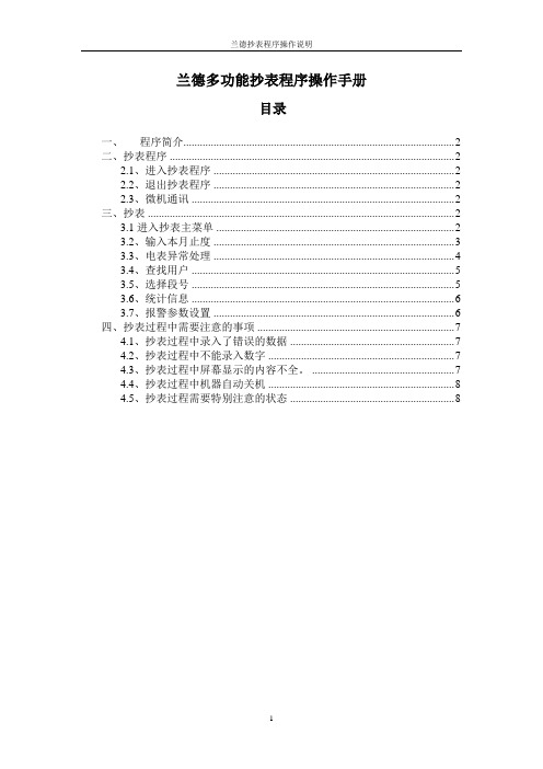
兰德多功能抄表程序操作手册目录一、程序简介 (2)二、抄表程序 (2)2.1、进入抄表程序 (2)2.2、退出抄表程序 (2)2.3、微机通讯 (2)三、抄表 (2)3.1进入抄表主菜单 (2)3.2、输入本月止度 (3)3.3、电表异常处理 (4)3.4、查找用户 (5)3.5、选择段号 (5)3.6、统计信息 (6)3.7、报警参数设置 (6)四、抄表过程中需要注意的事项 (7)4.1、抄表过程中录入了错误的数据 (7)4.2、抄表过程中不能录入数字 (7)4.3、抄表过程中屏幕显示的内容不全。
(7)4.4、抄表过程中机器自动关机 (8)4.5、抄表过程需要特别注意的状态 (8)一、程序简介此程序按河北省电力公司《营销业务应用标准化设计接口方案——抄表机接口方案(版本号V0.87)》以及《20080825河北电力抄表机要求》进行编写。
此程序可以在兰德的各种机型(如HT1820、HT2680、HT2680A、HT2900、HT3300等)运行使用。
它能自动识别兰德的各种机型,自动适应各种机型的液晶屏幕大小。
也就是多种机型可以只使用此一个抄表程序。
二、抄表程序2.1、进入抄表程序抄表机长按键盘右下角的【开关】键将抄表机打开或关闭,若第一次打开抄表机时,自动进入“主控台”,显示如下图(图1)。
移动(上、下)键选择“1.执行程序”,然后按“确定”或者直接按数字【1】键,进入“执行程序”菜单。
移动(上、下)键选择“LDW ALKER.HTP”,按【确定】后,进入抄表程序登录界面。
2.2、退出抄表程序按【取消】键直到退出到程序的主菜单,移动(上、下)键选择“6.退出”,按【确定】键即可退出抄表程序2.3、微机通讯进入抄表机“主控台”后或者在“用户菜单”界面下选“文件服务器”,再按【确定】后进入微机通讯的菜单,让抄表机和微机连接就可以和微机通讯了。
关于各种机型的的通讯方式,请查看机器的用户使用说明书。
三、抄表3.1进入抄表主菜单首先需要进入“抄表界面”,界面内容如下图(图12)该界面是抄表人员接触最多的界面,也就是用户的基本资料。
兰德马克通讯2011年第四期
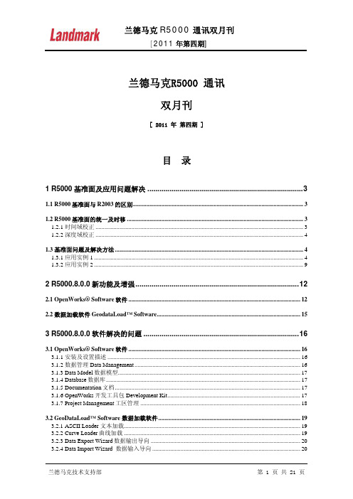
兰德马克R5000 通讯双月刊[ 2011 年 第四期 ]目录1 R5000基准面及应用问题解决 (3)1.1 R5000基准面与R2003的区别 (3)1.2 R5000基准面的统一及时移 (3)1.2.1 时间域校正 (3)1.2.2 深度域校正 (4)1.3 基准面问题及解决方法 (4)1.3.1 应用实例1 (4)1.3.2 应用实例2 (9)2 R5000.8.0.0新功能及增强 (12)2.1 OpenWorks® Software软件 (12)2.2 数据加载软件GeodataLoad™ Software (15)3 R5000.8.0.0软件解决的问题 (16)3.1 OpenWorks® Software软件 (16)3.1.1 安装及设置描述 (16)3.1.2 数据管理Data Management (16)3.1.3 Data Model数据模型 (17)3.1.4 Database数据库 (17)3.1.5 Documentation文档 (17)3.1.6 OpenWorks开发工具包Development Kit (17)3.1.7 Project Management工区管理 (18)3.2 GeoDataLoad™ Software 数据加载软件 (19)3.2.1 ASCII Loader 文本加载 (19)3.2.2 Curve Loader曲线加载 (19)3.2.3 Data Export Wizard数据输出导向 (20)3.2.4 Data Import Wizard 数据输入导向 (20)3.2.5 Documentation文档 (20)3.2.6 数据传输 (21)3.2.7 SEGY 数据加载 (21)3.2.8 井数据输出Well Data Export (21)1R5000基准面及应用问题解决1.1R5000基准面与R2003的区别2003:1.假设所有的测线或测网显示的是同一个工区基准面2.Seisworks/3d 中工区基准面设置和地震数据集处理的基准面相同3.Seisworks/2d需要定义工区基准面,但是由于不同年度采集处理的测线可能有着不同的地震基准面,因此工区基准面设置为和测线数相对较多的地震数据一致,其他测线通过常数时移调整到工区基准面R5000:1.消除了地震工区,引入了解释工区,基准面、常数时移和变时移文件现在存储在openwork中,如果你加载的数据基准面不一致,你可以产生一个解释工区实现基准面的匹配。
2024版rslogix5000软件培训ppt课件

2024/1/26
1
目 录
2024/1/26
• 软件介绍与安装 • 基本功能与操作 • 高级功能与特性 • 案例分析与实践操作 • 故障诊断与排除方法 • 总结回顾与拓展延伸
2
01
软件介绍与安装
2024/1/26
3
RSLogix5000软件概述
2024/1/26
生产线自动化改造效果评估与改进
介绍如何对生产线自动化改造的效果进行评估,以及如何进行持续改进和优化,提高生 产效率和产品质量。
21
05
故障诊断与排除方法
2024/1/26
22
常见故障类型及原因分析
软件崩溃或无法启动
可能是由于系统兼容性问题、软件bug或硬件故障等 原因导致。
程序无法下载或上传
可能是由于通信故障、硬件连接问题或程序错误等原 因导致。
2024/1/26
20
案例三:生产线自动化改造项目
生产线自动化改造需求分析
分析生产线自动化改造的需求和目标,确定改造的范围和重点。
RSLogix5000软件在生产线自动化改造中的应用
讲解如何使用RSLogix5000软件进行生产线自动化改造的规划和实施,包括设备选型、 控制系统设计、网络通信等。
2024/1/26
添加编程元素
从元素库中选择需要的编程元素,如 输入/输出模块、数据处理器、通信 接口等。
编辑编程元素
修改元素属性、设置参数、编写控制 逻辑等。
2024/1/26
元素间连接
通过连接线将不同元素连接起来,实 现数据交换和控制逻辑。
编程规范与技巧
遵循一定的编程规范,提高程序的可 读性和可维护性;掌握一些编程技巧, 提高编程效率和质量。
Discovery5000[1].0.0.0技术说明
![Discovery5000[1].0.0.0技术说明](https://img.taocdn.com/s3/m/76e1402c647d27284b735175.png)
Discovery综合油藏研究工作平台技术说明GNT国际公司2009年目录1 概况.................................................................................................... - 1 -2 软件模块及功能说明 ....................................................................... -3 -2.1 Discovery软件模块清单.......................................................... - 3 -2.2 Discovery软件模块详细功能说明.......................................... - 4 -3 软件运行环境及硬件配置要求 ..................................................... - 12 -4 软件的许可证管理 ......................................................................... - 13 -1 概况GNT国际公司在中国石油工业推广的Landmark Discovery软件,是由美国Landmark公司在Windows环境下开发的微机版综合油藏地质研究产品,现已广泛应用于中国各大石油公司。
针对不同的地质情况,Discovery能够提供一整套有效的解决方案,把地质研究、地震解释、测井分析、开发生产动态管理集成到一个完整的解释系统中,形成微机版一体化油藏描述平台,进而完成各类勘探开发项目研究工作。
Discovery自1999年发布以来,其技术得到了不断的发展和完善。
目前最新版本为5000.0.0.0,其主要新功能有:●Discovery on OpenWorks和OpenWorks 5000无缝连接。
兰德马克软件简介
Seismic processingPoststack/PAL/ESP:叠后解释性处理软件,可做各种叠后处理,如滤波、反褶积、振幅修饰性处理、去噪处理,层拉平,道积分,三瞬等属性。
/地震属性提取,可沿层提取50种属性,沿目的层的波形分类,是油藏描述进行多参数分析,模式识别,地震相分析的重要工具。
/生成相干数据体,速度反演数据体等多种属性,或沿层进行相干属性分析。
SeisSpace/PROMAX2D:常规二维处理转换波/多分量等SeisSpace/PROMAX3D:常规三维处理,AVO,转换波/多分量等SeisSpace/PROMAX4D:四维时移地震处理SeisSpace/PROMAX Depthcharge:全新深度成像处理包SeisSpace/PROMAX VSP:垂直地震剖面处理Seismic interpretationFZAP:三维断层面自动拾取Geoprobe:真三维可视化解释系统,可对海量的三维地震数据进行快速准确地构造解释;提供多手段的储层研究;能快速搜索和雕刻地质异常体;有先进的属性实时计算分析。
LogM/STRUCT:曲线编辑,合成记录,正演,AVOOpenvision:强大的三维显示模块PowerCalculator:强大的层位计算,属性提取模块PowerView:新一代地震、地质解释、成图模块SeisCube:三维地震解释模块SeisWorks:经典的三维解释模块,三维地震数据解释和分析,平面属性计算与分析,体积计算,基本作图。
具有时间切片解释,层拉平及其层位解释,自动断层多边形生成等功能。
SeisWorks2D:经典的二维解释模块,二维地震数据解释和分析,闭合差校正,基本作图。
SynTool:制作合成记录Well Seimic Fusion:新一代地震叠前解释、多井交汇分析、正演模拟,流体替换、地震处理及子波提取、AVO属性计算分析功能,进行岩性及流体预测。
ZAP:三维层面自动拾取UTILITIESCheckshot Data Manager:Checkshot管理器Seimic Balance:闭合差校正Seimic Data Manager:地震数据管理器Seimic Datacheck:三维数据检查器Seimic Datacheck 2D:二维数据检查器Seimic I/O Tools:地震数据体转换、层位断层管理/输入输出、不同工区数据体传输Seimic List Manager:二维测线管理器Surface/Fault Data Manger:分层/断层管理器Well Curve Viewer:曲线浏览Well Data Manager:井数据管理器Attribute &VelocityDepthTeam Explorer:三维变速速度场建模,针对较为复杂的地质目标,即构造倾角大,速度横向或纵向梯度变化大。
POSIDRIVE MDS 5000商品说明书
With the development of thePOSIDRIVE ®MDS 5000 servoinverter, STÖBER ANTRIEBS-TECHNIK is launching a totalrevision of the hardware andsoftware for the servo system.The data communication between the POSIDRIVE ® MDS 5000 and the STOBER ED EK and EZ synchronous servo motors is now entirely digital.The main factor allowing rationalrealization of this fully digital ser-vo axis lies in the developmentof fully digital absolute encodersat industrial-scale prices. TheSTOBER synchronous servo mo-t ors in the ED, EK and EZ series are equipped with these devices.Innovative software generation The commissioning software POSITool is based on a com-pletely new, mo d ular 3-layer architecture with ergo n o m ic interface de s ign. An ap p li c ations library with pa - r am e terization assistant and an additional flexible graphics pro -gramming facility forms a suc -cessful bridge between custom-made design and universality.This new system technologybrings to an end the era of over-loaded and confusing operatingprograms from the pioneering period of inverters.The benefits are obvious This comprehensive and rational slimming down of the sys t em results in significant cost bene-fits for hardware, configuration,cabling, installation and com -mis s ioning.The close coordination of all the STOBER servo components is clear from the example of the electronic motor rating plate.Its data is used automatically in the parameterization of the POSIDRIVE ®MDS 5000 servo inverter.THE FIRST COMPLETE SYSTEMFOR EFFICIENT AUTOMATIONTHE FULLY DIGITALPOSITIONING AXISSTOBER EK synchronous servo motorwith digital absolute valuator(standard version)2Multiple use by alternatecontrol of different servodrivesServo drives often go into actionat timed intervals. Typical exam-ples of this are handling opera-tions and format adjustments.Multimotor operation with onlyone POSIDRIVE ®MDS 5000servo inverter is suitable forthese applications.The digital technology makes it possible For the first time the inexpensiveand reliable axis changeoverapplication is available for un -restricted use on servo drives.Axis changeover switchThe POSISwitch ®AX 5000 exter-nal module has been developedfor connection of the digitallycontrolled synchronous servomotors. Actuation is just via theexisting encoder cables, with-out further operations.Power and signal flows are controlled with correct timing.The axis management does not require additional software complexity in a primary control.Sequential operation with -out functional limitation If four drives are used as end -less axes with absolute encod -ers, the exact positioning is stillfree from rounding errors evenif the gear units have differentand non-integer gear ratios.POSISwitch ®AX 5000Software The POSITool software can man -age up to four separate position or speed regulated axes and control them alternately.A smooth transition from axis to axis is guaranteed by thesoftware.ALTERNATECONTROL OF SEVERALSERVO DRIVES3For experts The new, user programmable firmware has been upgraded to include a graphics editor layer in conformance with PLCopen ®.An experienced or trained user will find a variety of predefined function blocks in various libra-ries. With these, basic applica-tions can be modified or given extra functions.Extra service For a completely new functio-nality requirement or for com -prehensive adaptation of the basic application, STÖBER ANTRIEBSTECHNIK offers this as "tailor-made applications"service.Other highlights The software scalability allows optimum adaptation of functio-nality and response time to the application. The cycle time for setpoint processing depends only on the calculation of the activated system modules and the plex applications can also be mapped on the same hard-ware platform without modify-ing the firmware.The STOBER POSISwitch ®AX 5000 axis changeover switch is prepared for use on the soft-ware side. Up to 4 servo axes with different functionalities can be controlled alternately.The rapid pace of developmentsin electronics is leading to con -tinuous improvements and ex -panded functions, especially inservo inverters, and yet this isassociated with constant growthin user software com p lexity. Atrend which is in stark contrastto the demand for sim p ler andmore accurate usability.This conflict of objectives hasbeen addressed by STÖBER ANTRIEBSTECHNIK and Soft-ware Suite V5 developed as a solution. This suite includesthe commissioning softwarePOSITool, a comprehensivelibrary with standard applica-tions, as well as the firmwarefor the inverter generation 5000.Instead of rigidly defined firm-ware with an endless numberof parameter variations the userhas a modern, ergonomicallydesigned operator interface.MODULARSOFTWARE ARCHITECTUREMODULAR H Functional housing design As part of the STOBER EMC strategy, all the housings in the POSIDRIVE ®MDS 5000 series are made of galvanized sheet steel. They shield against elec-tromagnetic interference and thus increase the units' RFI immunity and reduce interfe-rence emission.The front housing is made of high-impact plastic and incor -porates the operator keypad,display, LED indicators, Para -modul and RS232 interface,along with the slots for the op -tional boards and terminals.The same design plastic front housing is used for all the sizes.SYSTEM CONCEPT OF TOTAL MODULARITY Paramodul Plug-in memory module for transf er of all program and set -tings data.If a POSIDRIVE ®MDS 5000 has to be replaced, the existing Paramodul is simply plugged in again to restart operations. The functionality is retained without restriction. This plug-in memory module is also an ideal, immediately avail -able tool for documentation up -dating of operating conditions.4For everyday To configure a drive, the com-missioning software POSITool offers a li b rary with typical preproduced basic applications.Here is a selection:b Fast reference value b Comfort reference value Speed or torque reference value (selectable)3 analog reference values 16 fixed reference valuesMotorized potentiometerPID controller reference valueReference values scalable asabsolute or percentage valueb Command positioningPowerful single axis position-ing control with commandinterface in accordance withPLCopen ®and the additionalfunction POSILatch. Positionmeasurements can then betaken on external signals(e.g. linear measurements)b Motion block positioningb Electronic cam functionConnection of up to 32 axesThe consistent project orienta-tion of the modules is provingextremely effective.The parameterization work issupported by assistant func-tions.EMC shield, the motor cable shield connected with a clipOn the right: Version with integral brake module for 24 V brake ARDWARE STRUCTUREDP 5000PROFIBUS DP-V1CAN 5000CANopen DS 301Optional fieldbus communicationOptionalI/O interfacesSupply connection 3 x 400 VoltsXEA 5001I/O terminal module – expanded –3 analog inputs (1 x 16 bit, 2 x 12 bit)2 analog outputs 13 binary inputs 10 binary outputs 2 x D-SUB 9 incremental encoder (TTL) or SSI Input/output interface (X20 – SDS compatible)SEA 5001I/O terminal module– standard –2 analog inputs (12 bit)2 analog outputs5 binary inputs2 binary outputsEncoder interfaces for 4 systems:EnDat digital (bidirectional synchronous serial interface)SSI-AbsoluteTTL incremental encoder (RS422, “5V”)HTL incremental encoder (“24V”)24 Vsupply 5ECS 5000EtherCAT PROFINETREA 5001I/O terminal module – Resolver –2 analog inputs, 2 analog outputs 5 binary inputs, 2 binary outputs Encoder:Resolver EnDat -Encoder 2.1TTL incremental encoder*SSI encoder*Stepper motor signals*The adapter is included in the scope of delivery of the REA 5001*(Simulation and evaluation)THE COMPLETE RANGEFROM 0.37 TO 45 KW Installation The POSIDRIVE servo inverters can be mountedin compact control cabinets300 mm deep.The operator module is thesame for all the sizes.The sheet steel housing designis part of the STOBER EMCstrat e gy (filter class A). It shieldsagainst electromagnetic inter-ference.6This increases the units' RFI immunity and reduces interfe-rence emission. The front is the only part made of plastic which is pleasant to the touch.Functional modular housing designMDS 5007A/5008A/5015A MDS 5040A/5075A MDS 5110A/5150A MDS5220A/5370A/5450ASYSTEM BASISPowerful processor core32-bit RISC processorCurrent controller 125 µs Control modes Synchronous servo motors Asynchronous motors (V/f, sensorless VC, VC)Encoder interface Absolute encoder, digital (EnDat ®, SSI)Incremental encoder (TTL, HTL)Optional: Resolver Serial interface RS232 with USS protocol Option board slots Communication I/OTerminals Operational reliability Generously sized power stage for 250 % accelerating current Thermistor motor protection PTC thermistor monitoring Brake chopper integral Thermal model monitoring of external resistor for short circuitand overload DC link connection For energy exchange between several inverters Operator unit 8 keys, changing of parameters,manual operation (clear text display and LED indicators)Paramodul Plug-in module for power failu-re safe storage of all application specific data.Data transfer without any fur -ther aids Control electronics supply Power supply unit with connec-tion facility for external +24V orDC link power supply(the control section remainsfully functional even if the sup -ply voltage is switched off)Ease of installation All terminals plug-in type (spring-loaded terminals)Supply and motor connectionsin separate placesDC link terminals, two of each,facilitate parallel connectionEMC plate for shield connection ASP 5001 Option for the implementation of safety functions:b STO and SS1 as perEN 61800-5-2b Stop category 0 and stopcategory 1 as perEN 60204Integration is possible forapplications up to (max.):b PL e in category 3 as perEN ISO 13948-1:2008-12 andb SIL 3 as perEN 61800-5-2:2008-04The POSILatch function uses externalsignals and evaluates them as measure-ment function.POSILatch can replace a separate PLCmeasuring system7POSITool Windows Software Application selection (with assistant)Parameterization (with assistant)Manages several servo inverters in one installationDrive optimization with POSI-Scope, oscilloscope function forinternal signals (movementvisualization), operational datamonitoring and diagnosisFieldbus communication PROFIBUSPROFINETEtherCAT®CANopen®I/O terminal moduleSEA 5001XEA 5001 (incremental encoder and SSI interfaces)REA 5001Resolver andEnDat®Encoder 2.1 interfacePOSISwitch®AX 5000For sequential control of STOBER ED, EK and EZ synchronous ser-vo motors with digital absolute encoders.Submountedbraking resistorsBraking resistors for installation at the rear of the unitBraking resistorVHPR seriesIP 54 enclosure, ULVHPRBraking resistorASP 5001Starting lockoutSYSTEM OPTIONSCE complianceAll POSIDRIVE®MDS 5000 inver-ters conform to the applicableEMC Directives and meet thecriteria of Low Voltage DirectiveEN 50178. Standard featurescomprise an effective range ofmeasures, among them an in -tegral EMC filter and the high-quality galvanized sheet steelinverter housing.Levels and terms apply as de -fin e d by IEC 1131.All POSI D RIVE®servo invertersare CE-markedUL compliantThe inverters are UL and cUL("Canadian UL") listed and meetthe requirements of UL 508Cand UL 840 standardsAbsolute Encoder Support AESFor buffering supply voltagewhen using the inductive Multi-turn EnDat®2.2 absolute encoderEBI1135 (when the 24 V powerCommissioningfer via the device operator panel.The Paramodul is also suit a ble for data transfer. Further pa -rameterization cor r ections and additions can be made directly.Some knowledge (basic training)is necessary for this missioning the STOBERED, EK and EZ synchronousservo motorsNo software knowledge is neces-sary for this preparation work.All the adjustments are done bydialog via the operator panel withtext display. The POSIDRIVE ®MDS 5000 servo inverter comessupplied with the “rapid set point”application.synchronousservo motorwith digitalabsolute encoderon the motorshaft (B side)Advanced seminars for general users and experts The POSITool software assistant supports configuration and pa-rameterisation of the STOBER standard applications. Basic andadvanced information on the safehandling of POSITool necessaryon the job can be acquired at anapplication seminar.In practical, individually designedseminars, general users learnthe ways in which they can uti-lise the potential of the POSIToolstandard applications fully andeffectively.After attending the ‘Free GraphicProgramming’ seminar, expertscan expand the POSITool stan-dard applications themselvesto adapt them to specific needs.Further information and datescan be found on our websitewww.stoeber.de (Services).ServiceThe STOBER service system comprises38 expert partners in Germany andmore than 80 companies in the STOBERSERVICE NETWORK worldwide.This full service concept guaranteeslocal expertise and availability whenneeded.In general, the service specialists can bereached at any time via a 24/7 servicehotline.When necessary, a problem can beaddressed immediately.24/7 service hotline+491805786323QUICK TO ASSEMBLESubjecttotechnicalchanges441812.7www.wast.deQuick DC link connection.Double DC link permit enablesimplified parallel connection.The separate connections formotor, DC link and braking re -sistor are located on the bot t omof the housing. The PTC therm -istor and braking relay are alsoattached here by simple plug-inmounting.VERY EASY TO USEEasy data transfer and accep-tance by Paramodul.Display and keypad are inte-grated. Rapid diagnosis, statusmonitoring, direct parameteraccess and manual operatingfunctions are possible.Perfect, practical connectionlayoutThe mains or 24V supply con -nection is made ‘from above’through a plug-in terminal strip.STOBER AUSTRIAwww.stoeber.at+43 7613 7600-0****************STOBER CHINA+86 10 6590 7391****************STOBER FRANCEwww.stober.fr+33 4 78.98.91.80***************STOBER GERMANYwww.stoeber.de+49 7231 582-0****************STOBER ITALYwww.stober.it+39 02 93909570***************STOBER JAPANwww.stober.co.jp+81 3 5395 6788***************.jpSTOBER SOUTH EAST ASIAwww.stober.sg+65 65112912***************STOBER SWITZERLANDwww.stoeber.ch+41 56 496 96 50****************STOBER USA+1 606 759 5090****************。
兰德马克DSG5000.10软件2015年度第一期通讯1.0
2015年1月8日目录目录 (1)1.DSG5000.10 Geophysics模块新功能 (2)1.1WellTie功能更加完善和强大 (2)1.2速度建模增加了新功能 (13)2.DSG5000.10 Geology模块新功能 (15)2.1 连井地层对比增加了多种新功能 (15)2.2 新增加了剖面线的功能,使井投影更加方便控制 (18)2.3 新增加了在平面图上沿井轨迹显示测井曲线 (21)2.4 更加细分了曲线拖拽对比的功能 (24)2.5 新增了井分层的分析功能 (25)2.6 新增了平面等值线的平滑和滤波功能 (26)2.7 在曲线计算模块新增加了曲线标准化的功能 (28)3.DSG5000.10 Dynamic Frameworks to Fill模块新功能 (29)3.1 DFF主界面布局发生了改变,增加了新的控制选项 (29)3.2 DFF增加了用Polygon的方法控制模型边界 (32)3.3 DFF增加了自定义断层与层位的封堵性 (32)3.3DFF里面支持直接把层段模型转换为GeoShell (33)3.4DFF里面断层和层位的接触关系编辑起来更加方便 (33)4.G15000.10 功能更加完备、成熟 (34)2015年1月8日1.DSG5000.10 Geophysics模块新功能DSG5000.10版本在地球物理模块重点针对井震标定、速度建模等方面有了较大的提高和更新。
下面就这些新功能给大家做个简单的介绍。
1.1WellTie功能更加完善和强大1.1.1在新版本中,支持斜井沿实际井眼轨迹显示数据及合成记录,在SelectSeismic 的步骤,点击可以选择插入一道沿着斜井轨迹,同时显示过井地震剖面和合成记录。
2015年1月8日1.1.2新添加了支持曲线道设置的拷贝、粘贴功能。
首先在点击添加一个新的道2015年1月8日对已经设置好的曲线道,右键点曲线名,选择Copy settings of然后鼠标移动到新加道里,激活道头,右键选择Paste setting from2015年1月8日1.1.3在保存合成记录的界面,新增加了保存控制点以及时深曲线可以按照自定义时间间隔保存。
pulse secure psa5000 硬件指南说明书
PSA5000 硬件指南版权所有 © 2014-2016, Pulse Secure, LLC.保留所有权利。
所有商标均归其各自所有者所有。
所有规格如有变更,恕不另行通知。
对于本文档中的任何不准确之处,Pulse Secure, LLC 不承担任何责任。
Pulse Secure, LLC 保留变更、修改、转让或以其他方式修订本出版物的权利,恕不另行通知。
联系 Pulse Secure:Pulse Secure, LLC2700 Zanker Road, Suite 200San Jose, California 95134目录系统概述简介 (5)LED 控制面板 (5)控制面板按钮 (6)控制面板 LED 灯 (6)硬件规格系统测量 (9)额定功率 (9)环境要求 (10)组件规格 (10)监管认证 (10)安装至机架 (10)从哪里取得替换组件 (11)控制台与初始配置打开系统电源 (13)配置基本设置 (14)更改个性 (15)配置示例 (17)开启核心服务 (17)关闭系统 (19)访问网页管理界面 (19)为系统签发许可证 (20)安装准备安装 (22)选择安装位置 (22)机架物理预防措施 (23)一般服务器预防措施 (23)机架安装说明 (24)将机箱安装至标准机架 (24)标准警告与合规性关于标准警告 (26)安全认证 (26)电气安全 (26)一般安全 (27)安装说明 (27)断路器 (27)断电警告 (27)设备安装 (28)限制区 (28)冗余电源供电 (28)背板电压 (28)请遵守本地与本国电气法规 (28)产品废弃处理 (29)热插拔风扇警告 (29)电源电缆和 AC 适配器 (29)认证声明 (29)系统概述简介PSA5000 独特且高度优化的设计可用于小功率处理器平台。
配备效率增加 80%、低噪音的 200W 电源。
高性能风扇提供充分优化冷却。
本地管理控制台内部端口 (INT)电源开关远程网络管理外部端口 (EXT)注:为了增加系统安全性,已禁用 USB 接口。
兰德华电子巡检管理系统专业版B1.0说明书
巡检管理系统专业版B1.0说明书目录一、软件功能特性 (3)二、软件使用说明 (2)(一)基本使用流程 (2)(二)软件登录及退出 (2)1.软件登录 (2)2.系统注销 (2)3.软件退出 (3)(三)基础设置 (3)1.地点设置 (3)2.人员设置 (4)3.事件设置 (5)4.棒号设置 (6)(四)地图设置 (7)(五)采集数据 (8)1.巡检记录 (8)2.人员钮 (8)3.地点钮 (8)4.事件钮 (8)5.棒号 (9)(六)数据查询 (9)1.删除一条、删除全部 (10)2.地图演示 (10)3.图形分析 (10)(七)计划设置 (12)(八)计划考核 (13)(九)参数设置 (14)1.串口号 (14)2.登录密码 (14)3.删除数据 (14)4.初始化 (14)5.自动备份 (14)(十)数据备份 (15)(十一)数据还原 (15)(十二)退出系统 (16)三、巡检器USB驱动安装 (17)(一)安装驱动 (17)(二)查看虚拟出来的串口号 (19)(三)在软件内设置串口号 (19)一、软件功能特性本系统采用多种先进数据处理技术,大大增强软件整体运行速度,对于普通的单机版软件具有下列优势。
1.绿色版,当软件安装成功之后,若需要重新安装操作系统或者将软件移植到其他电脑,只需要通过移动存储设备,如U盘或者移动硬盘,将整个软件安装后的文件夹拷贝至新的电脑后,即可使用。
2.采用后台处理技术以及窗口停靠功能,闲暇时刻,可以将程序最小化到操作系统的任务栏处,美观实用,也可以将软件拖放到屏幕最上方后,缩小成一个小型图标。
3.数据自动生成功能。
在软件内设置巡逻计划后,操作系统到达新的日期后,软件会自动生成当前日期至上一次最后生成数据的日期之间所有系统数据。
无需人员干预。
4.数据自动分析功能。
巡逻人员巡逻后,将巡检器与电脑正常连接后,将数据在软件内采集后,软件会自动进行巡逻计划的分析考核,领导查阅数据时,可以直接调看巡逻考核的情况,而无需后期长时间的分析等待后再查看相关的巡逻情况。
兰德系列传感器模拟器操作手册说明书
5.0 Product Specifications ................................................................................................................... 9
3.0 Ranger 7 Simulator Operation ........................................................................................................ 6
3.1 Standard Operation . . . . . . . . . . . . . . . . . . . . . . . . . . . . . . . . . . . . . . . . . . . . . . . . . . . . . . . . . . . . . . . . 6 3.1.1 Switches. . . . . . . . . . . . . . . . . . . . . . . . . . . . . . . . . . . . . . . . . . . . . . . . . . . . . . . . . . . . . . . . . . . . . . . . . . 6 3.1.2 Toggle Switch Load Control . . . . . . . . . . . . . . . . . . . . . . . . . . . . . . . . . . . . . . . . . . . . . . . . . . . . . . . . . . . 6 3.1.3 EXC LEDs . . . . . . . . . . . . . . . . . . . . . . . . . . . . . . . . . . . . . . . . . . . . . . . . . . . . . . . . . . . . . . . . . . . . . . . . . 6 3.1.4 To Simulate a Larger Load . . . . . . . . . . . . . . . . . . . . . . . . . . . . . . . . . . . . . . . . . . . . . . . . . . . . . . . . . . . . 6
安装说明-Compact 5000 I O 数字量 8 点安全拉出型输入模块说明书
安装说明Compact 5000 I/O 数字量 8 点安全拉出型输入模块目录号 5069-OBV8S 、5069-OBV8SKThe 5069-OBV8S 和 5069-OBV8SK 模块是 8 点安全拉出型输入模块。
这些模块在安全控制网络上提供满足以下要求的安全 I/O ,该等要求包括 SIL CL3 和 PLe, Cat. 4,如 IEC 61508、IEC 61511、IEC 62061 和 ISO 13849-1 中所规定。
该模块提供拉出型输出和双极性类型输出。
您可将 Compact 5000™ I/O 安全模块用作带 CompactGuardLogix®5380 控制器的本地和远程 I/O 模块,以及带 Compact GuardLogix 5380 和 GuardLogix 5580 控制器的远程 I/O 模块。
5069-IB8SK 模块提供与 5069-IB8S 模块相同的功能,但具有保形涂层,有助于在恶劣环境中提供保护。
使用 Studio 5000 Logix Designer® 软件配置模块。
Compact GuardLogix 5380 和 GuardLogix 5580 控制器必须使用 32.011 或更高的固件版本,才可使用 Compact 5000 I/O 安全模块。
Compact 5000 I/O 安全模块采用生产者/消费者通信模式。
生产者/消费者通信模式是模块与其他系统设备之间的一种智能数据交换,在通信过程中,每个模块都会生成数据,而不是先被轮询。
有关如何使用 Compact 5000 I/O 模块的更多信息,请参见第12页的其他资源中列出的出版物。
变更摘要主题页码关于模块5安装系统5安装可拆卸端子块7安装模块8安装终端盖9对可拆卸端子块进行接线9断开电线与可拆卸端子块之间的连接9使用束线带10为系统供电10拆卸模块10技术参数11其他资源12主题页码删除接线图有关如何连接模块的信息,请参阅中第12页的其他资源列出的出版物不适用Compact 5000 I/O 数字量 8 点安全拉出型输入模块ATTENTION:Read this document and the documents listed in the Additional Resources section about installation, configuration and operation of this equipment before you install, configure, operate ormaintain this product. Users are required to familiarize themselves with installation and wiring instructions in addition to requirements of all applicable codes, laws, and standards.Activities including installation, adjustments, putting into service, use, assembly, disassembly, and maintenance are required to be carried out by suitably trained personnel in accordance with applicable code of practice.If this equipment is used in a manner not specified by the manufacturer, the protection provided by the equipment may be impaired.注意:在安装、配置、操作和维护本产品前,请阅读本文档以及“其他资源”部分列出的有关设备安装、配置和操作的相应文档。
兰德马克R5000系列软件大大提高储集层解释能力
兰德马克R5000系列软件大大提高储集层解释能力
佚名
【期刊名称】《石油工业计算机应用》
【年(卷),期】2009(000)001
【摘要】在2008年EAGE(欧洲地球物理学家和工程师协会)年会上,兰德马克公司首次展示R5000系列软件,在同步推出的70个应用软件中,该软件系列横跨了勘探开发领域的所有学科,是具有里程碑历史意义的软件系列。
【总页数】1页(P57)
【正文语种】中文
【中图分类】TE243
【相关文献】
1.储集层产出能力定量荧光录井解释评价方法 [J], 马青春;马红;杨立华;薛明侠;焦香婷;窦如俊;李艳;李红梅;王海燕
2.兰德马克公司开发出新一代定向井设计软件包 [J], 尤闻
3.Oracle钱包在R5000软件登录数据库的应用 [J], 李明;
4.兰德马克与挪威国家石油公司联手开发地震解释系统 [J],
5.说说人机联作兰德马克机地震解释系统 [J], 王之前
因版权原因,仅展示原文概要,查看原文内容请购买。
RIGOL DSG3000 RF信号生成器系列产品介绍说明书
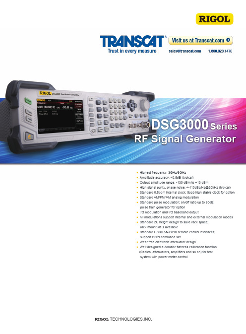
Highest frequency: 3GHz/6GHzAmplitude accuracy: <0.5dB (typical)Output amplitude range: -130 dBm to +13 dBmHigh signal purity, phase noise: <-110dBc/Hz@20kHz (typical) Standard 0.5ppm internal clock; 5ppb high stable clock for option Standard AM/FM/ΦM analog modulationStandard pulse modulation; on/off ratio up to 80dB;pulse train generator for optionI/Q modulation and I/Q baseband outputAll modulations support internal and external modulation modes Standard 2U height design to save rack space; rack mount kit is availableStandard USB/LAN/GPIB remote control interfaces; support SCPI command setWear-free electronic attenuator designWell-designed automatic flatness calibration function (Cables, attenuators, amplifiers and so on) for test system with power meter controlRIGOL TECHNOLOGIES,INC.DSG3000 Series RF Signal GeneratorDimensions: W × H × D = 364 mm × 112 mm × 420 mm; Weight: 6.4kg (without packag)Standard GPIB/USB/LAN interfaces10 MHz reference clock IN/OUTI/Q modulating signal input and baseband signal outputPulse modulation input, pulse gated signal input, pulse signal generator outputTrigger in/signal valid output/sweep progress output designed for system integrationHigh stable OCXO reference clock (option)Support USB storage device, power meter sensor or power meter with USB interfaceMain FunctionsPreset/View/HelpSignal output switchesPower key with delay switching designRF signal outputMain function keysFlexible and easy-to-use editing keyboard4.3 inches TFT LCDMenu keysSystem functionManual trigger LF signal outputExternal modulation inputSpecificationsFrequencySpecifications are valid under the following conditions: the instrument in the calibration cycle is stored at least two hours at 0°C to 50°C temperature, and 40 minutes warm up. The specifications include measurement uncertainty. Data represented in this manual are specifications unless otherwise noted.Typical (typ.): describes characteristic performance, which 80 percent of the measurement results will meet at room temperature (approximately 25 °C). This data is not warranted, does not include measurement uncertainty.Nominal (nom.): indicates the expected mean or average performance, or an attribute whose performance is by design,such as the 50Ω connector. This data is not warranted and is measured at room temperature (approximately 25 °C).Measured (meas.): describes an attribute measured during the design phase for purposes of communicating expected performance,such as amplitude drift vs. time. This data is not warranted and is measured at room temperature (approximately 25 °C).NOTE:All charts represented in this manual are the measurement results of multiple instruments at room temperature unless otherwise noted.NOTE: [1] Except in the case of the band1 is switched with another band.[2] N is a factor used to help define certain specifications within the document.NOTE: [1] Without IQ-DSG3000 option.Carrier frequency(MHz)Measured +13dBm output, Harmonics VS frequency H a r m o n i c s (d B c)Carrier frequency(MHz)Measured 0dBm output, Harmonics VS frequencyH a r m o n i c s (d B c )S S B p h a s e n o i s e (d B c /H z )Carrier offsetMeasured SSB phase noiseLevelFrequency(MHz)Minimum output level VS frequency M i n i m u m o u t p u t l e v e l (d B m )Maximum output level VS frequencyFrequency(MHz)M a x i m u m o u t p u t l e v e l (d B m )Measured maximum output level VS frequencyFrequency(MHz)M i n i m u m o u t p u tl e v e l (d B m)Time (hours)Measured level repeatability at 6GHz 0dBm, ALC ON, 25℃L e v e l (d B )NOTE: [1] ALC state: on or auto mode, 20℃ to 30℃[2] In 50Ω system, typical, level ≤-10dBm, ATT auto modeCarrier frequency(MHz)Carrier frequency(MHz)Carrier frequency(MHz)Carrier frequency(MHz)Measured +13dBm output level VS frequency Measured -60dBm output level VS frequency Measured -110dBm output level VS frequencyMeasured 0dBm output level VS frequencyL e v e l u n c e r t a i n t y (d B )L e v e l u n c e r t a i n t y (d B )L e v e l u n c e r t a i n t y (d B )L e v e l u n c e r t a i n t y (d B)Carrier frequency(MHz)Carrier frequency(MHz)Measured -127dBm output level VS frequency Measured -136dBm output level VS frequencyL e v e l u n c e r t a i n t y (d B )L e v e l u n c e r t a i n t y (d B )Internal Modulation Generator (LF)Modulation[2]NOTE: ○:compatible; ×: incompatible; △:compatible with AM performance reduced[2] The modulation source is sine waveform unless otherwise noted.[3]Peak power of the envelope is no more than the maximum value of the specification output range.[4] To ensure the modulation performance, the input amplitude of the external modulating signal should be less than ±0.5V.NOTE: [5] External operating mode, measured at 100kHz deviation.[6] External operating mode, measured at 5rad deviation.[7] The state of ALC is off.Pulse Generator Setting singledoubletraintriggerInternal modulationEVM16QAM , root cosine filter (α = 0.22), 4MSps 50MHz ≤ f ≤ 3GHz (level ≤ 4dBm)≤ 0.7%rms (typ.)3GHz < f ≤ 6GHz (level ≤ 0dBm)≤ 1.2%rms (typ.)QPSK , root cosine filter (α = 0.22), 4MSps 50MHz ≤ f ≤ 3GHz (level ≤ 4dBm)≤ 0.7%rms (typ.)3GHz < f ≤ 6GHz (level ≤ 0dBm)≤ 1.2%rms (typ.)External modulation EVM CDMA2000/1xEV-D0,1.2288 Mcps, frequency 800 to 900MHz, 1800 to 1900MHz, level≤4dBm ≤ 1.2%, ≤ 0.8% (typ.)ACPR≥ 70dBNOTE: [1] [2]The parameter is measured at room temperature. When the temperature is difference from room temperature, the specification will deteriorate.Frequency offset from carrier (MHz) Frequency offset from carrier (MHz)Carrier frequency (MHz)Carrier frequency (MHz)S u p p r e s s i o n o f i m a g e s i d e b a n d (d B c )Measured external IQ bandwidth Measured suppression of image sidebandMeasured carrier suppression Measured internal IQ bandwidthd Bd BInput and OutputNOTE: [1] Load from flash internal non-volatile memory.General SpecificationsOrdering InformationNOTE: All instruments, accessories and options can be ordered from your local RIGOL distributors.WarrantyThree -year warranty, excluding probes and accessories.RIGOL ® is the registered trademark of RIGOL Technologies, Inc. Product information in this document subject to update without notice. For the latest information about RIGOL 's products, applications and services, please contact local RIGOL office or access RIGOL official website: HEADQUARTERRIGOL TECHNOLOGIES, INC.No.156,Cai He Village,Sha He Town,Chang Ping District, Beijing,102206 P .R.China Tel:+86-10-80706688Fax:+86-10-80705070E l e c t r o n i c M e a s u r e m e n t Instrument service and support email:*********************Chemical Analysis Instrument service and support email:service.**************EUROPERIGOL TECHNOLOGIES GmbH Lindbergh str. 482178 Puchheim GermanyTel: 0049- 89/89418950Email:*************************NORTH AMERICARIGOL TECHNOLOGIES,USA INC.10200 SW Allen Blvd, Suite C Beaverton, OR 97005, USA Toll free: 877-4-RIGOL-1Office: (440) 232-4488Fax: (216)-754-8107Email:**************JAPANRIGOL TECHNOLOGIES JAPAN G.K.Tonematsu Bldg. 5F, 2-33-8 Nihonbashi-Ningyocho, Chuo-ku,Tokyo 103-0013 JapanTel: +81-3-6264-9251Fax: +81-3-6264-9252Email:********************November 2015。
COMPASS使用手册,兰德马克说明书

COMPASS for Windows for Windows of Landmark Graphics Co.简明使用手册目录一、COMPASS WELLPLAN FOR WINDOWS能简介二、COMPA NY SETUP - CREATE NEW COMP:公司设置-建立新的公司三、FIELD SETUP- CREATE NEW Fl:曲气田设置-建立新的油气田四、SITE SETUP- CREATE NEW SITE块设置-建立新的区块五、TEMPLATE EDITOR槽口模板编辑器六、WELLSETUP-CREATE NEW W E单井设置-建立新井七、WELLPATH SETUP-CREATE NEW WELLPAT迹设置-建立新的轨迹八、TARGET EDITOR?巴点编辑器九、NEW PLAN & OPEN PLAN井眼轨迹设计十、NEW SERVE Y& OPEN SERVE实测数据建立与编辑ANTICOLLISIO N防碰计算十WALL PLOT COMPOSERS 图制作十三、常用功能简介COMPASS WELLPLAN FOR WINDO功S B简介COMPAS(S 指南针)有三个核心功能:PLANNING (设计)按计划井眼形状设计井眼轨迹SURVEY(实测计算)已钻井眼实测数据的计算及轨迹预测ANTICOLLISION:防碰计算)井眼轨迹之间的距离计算除此之外,COMPAS还有以下功能:COMPANY SETUP 允许你为不同的公司设置COMPASSFIELD SETUP 为同一油田的所有平台定义通用的水平或垂直参考系统TARGET EDITOR 靶点编辑器,设置靶点位置及靶区形状TEMPLATE EDITOR 槽口编辑器,用于丛式井井口坐标计算REFERENCE DATUM ELEVATIONS^不同的海拔高度参照基准MAGNETIC CALCULATO R算不同磁场模型的磁场值GEODETIC CALCULATORS同地质坐标系之间的数值转换计算SURVEY TOOLS 定义不同测量工具的测量误差COMPANY SETUP - CREATE NEW COMPANY公司设置-建立新的公司建立一个新的公司,实际上就是为你建立的这个新公司对 COMPASS 件进行 一些基础参数设置,也就是 COMPANY SETUP 公司设置)。
DSG5000系列信号发生器说明书
保证和声明版权© 2022 普源精电科技股份有限公司商标信息RIGOL®是普源精电科技股份有限公司的英文名称和商标。
声明•本公司产品受中国及其他国家和地区的专利(包括已取得的和正在申请的专利)保护。
•本公司保留改变规格及价格的权利。
•本手册提供的信息取代以往出版的所有资料。
•本手册提供的信息如有变更,恕不另行通知。
•对于本手册可能包含的错误,或因手册所提供的信息及演绎的功能以及因使用本手册而导致的任何偶然或继发的损失,RIGOL 概不负责。
•未经 RIGOL 事先书面许可,不得影印、复制或改编本手册的任何部分。
产品认证RIGOL 认证本产品符合中国国家产品标准和行业产品标准及ISO9001:2015 标准和ISO14001:2015 标准,并进一步认证本产品符合其他国际标准组织成员的相关标准。
联系我们如您在使用此产品或本手册的过程中有任何问题或需求,可与 RIGOL 联系:电子邮箱:*****************网址:章主题页码插图目录 (IV)1安全要求 (1)1.1一般安全概要 (1)1.2安全术语和符号 (2)1.3测量类别 (3)1.4保养和清洁 (3)1.5环境注意事项 (4)2DSG5000系列仪器简介 (5)3文档概述 (6)4快速入门 (8)4.1一般性检查 (8)4.2外观尺寸 (8)4.3前面板概述 (9)4.4后面板概述 (11)4.5首次使用DSG5000 (13)4.5.1连接电源 (13)4.5.2仪器控制 (13)4.5.3开机检查 (14)4.5.4设置系统语言 (14)4.6更换保险丝 (14)4.7用户界面 (15)4.8使用内置帮助 (17)5键盘设置 (18)5.1参数键盘 (18)5.2输入法键盘 (20)6频率 (24)6.1频率设置 (24)6.2频率偏移 (24)6.3相位偏移 (24)6.4复位相位 (25)7电平 (26)7.1电平设置 (26)7.2电平限制值 (26)7.4平坦度校正 (27)7.5电平单位 (28)8扫描 (29)8.1扫描类型 (29)8.2扫描方式 (29)8.2.1步进扫描 (29)8.2.2列表扫描 (31)8.3扫描模式 (32)8.4触发 (33)9调制 (36)9.1幅度调制(AM) (36)9.1.1打开幅度调制 (36)9.1.2选择调制源 (36)9.1.3设置调制深度 (36)9.1.4设置调制频率 (37)9.1.5其他设置 (37)9.2频率调制(FM) (38)9.2.1打开频率调制 (38)9.2.2选择调制源 (39)9.2.3设置频率偏移 (39)9.2.4设置调制频率 (39)9.2.5其他设置 (39)9.3相位调制(PM) (40)9.3.1打开相位调制 (40)9.3.2选择调制源 (40)9.3.3设置相位偏移 (41)9.3.4设置调制速率 (41)9.3.5其他设置 (41)9.4脉冲调制(Pulse) (42)9.4.1打开脉冲调制 (42)9.4.2选择调制源 (42)9.4.3设置脉冲类型 (42)9.4.4脉冲其他设置 (43)9.4.5触发 (45)10系统设置 (47)10.1接口设置 (47)10.2复位 (49)10.3AUX (49)10.3.1 4.8 GHz信号输入输出 (49)10.4升级 (49)10.4.1本地升级 (50)10.4.2在线升级 (51)10.5系统 (51)10.6存储 (52)10.6.1存储 (52)10.6.2磁盘管理 (53)10.7帮助 (53)10.8设置 (53)10.8.1基本设置 (54)10.8.2自检 (54)11远程控制 (56)11.1通过USB控制 (56)11.2通过LAN控制 (57)12应用实例 (59)12.1输出RF信号 (59)12.2输出RF扫描信号 (60)12.3输出RF已调信号 (61)13故障处理 (62)14附录 (65)14.1附录 A: 附件与选件列表 (65)14.2附录 B: 保修概要 (65)插图目录图 4.1 正视图(单位:mm) (8)图 4.2 俯视图(单位:mm) (9)图 4.3 DSG5208前面板 (9)图 4.4 DSG5208后面板 (11)图 4.5 连接电源 (13)图 4.6 更换保险丝 (15)图 4.7 用户界面 (15)图 5.1 参数键盘 (18)图 5.2 中文输入法键盘 (20)图 5.3 英文输入法键盘 (22)图 5.4 数字输入法键盘 (23)图 8.1 递增扫描时的扫描形状示意图 (31)图 9.1 等幅度输出示意图 (38)图 9.2 触发延时示意图 (45)图 10.1 系统设置 (47)图 10.2 仪器文件资源管理系统 (50)1安全要求1.1一般安全概要了解下列安全性预防措施,以避免受伤,并防止损坏本产品或与本产品连接的任何产品。
- 1、下载文档前请自行甄别文档内容的完整性,平台不提供额外的编辑、内容补充、找答案等附加服务。
- 2、"仅部分预览"的文档,不可在线预览部分如存在完整性等问题,可反馈申请退款(可完整预览的文档不适用该条件!)。
- 3、如文档侵犯您的权益,请联系客服反馈,我们会尽快为您处理(人工客服工作时间:9:00-18:30)。
2015年1月8日目录目录 (1)1.DSG5000.10 Geophysics模块新功能 (2)1.1WellTie功能更加完善和强大 (2)1.2速度建模增加了新功能 (13)2.DSG5000.10 Geology模块新功能 (15)2.1 连井地层对比增加了多种新功能 (15)2.2 新增加了剖面线的功能,使井投影更加方便控制 (18)2.3 新增加了在平面图上沿井轨迹显示测井曲线 (21)2.4 更加细分了曲线拖拽对比的功能 (24)2.5 新增了井分层的分析功能 (25)2.6 新增了平面等值线的平滑和滤波功能 (26)2.7 在曲线计算模块新增加了曲线标准化的功能 (28)3.DSG5000.10 Dynamic Frameworks to Fill模块新功能 (29)3.1 DFF主界面布局发生了改变,增加了新的控制选项 (29)3.2 DFF增加了用Polygon的方法控制模型边界 (32)3.3 DFF增加了自定义断层与层位的封堵性 (32)3.3DFF里面支持直接把层段模型转换为GeoShell (33)3.4DFF里面断层和层位的接触关系编辑起来更加方便 (33)4.G15000.10 功能更加完备、成熟 (34)2015年1月8日1.DSG5000.10 Geophysics模块新功能DSG5000.10版本在地球物理模块重点针对井震标定、速度建模等方面有了较大的提高和更新。
下面就这些新功能给大家做个简单的介绍。
1.1WellTie功能更加完善和强大1.1.1在新版本中,支持斜井沿实际井眼轨迹显示数据及合成记录,在SelectSeismic 的步骤,点击可以选择插入一道沿着斜井轨迹,同时显示过井地震剖面和合成记录。
2015年1月8日1.1.2新添加了支持曲线道设置的拷贝、粘贴功能。
首先在点击添加一个新的道2015年1月8日对已经设置好的曲线道,右键点曲线名,选择Copy settings of然后鼠标移动到新加道里,激活道头,右键选择Paste setting from2015年1月8日1.1.3在保存合成记录的界面,新增加了保存控制点以及时深曲线可以按照自定义时间间隔保存。
1.1.4在新的选取子波的种类由以前的3种类型,增加到6种类型。
在选取合成记录的界面,选择Wavelet Type的下拉菜单可以看到,有Rick wavelet、Butterworth wavelet、Trapezoid wavelet、Extracted wavelet、Openmorks、ASCII几种类型。
2015年1月8日选择显示子波后可以查看选择的子波特征在当前状态下可以添加更多的子波进来用于对比2015年1月8日1.1.5在子波编辑栏中,新增加了重采样和平均子波的功能。
选择重采样后,可以对选择的子波进行自定义间隔采样,确定后会自动生成一个新的子波,名字中包含间隔信息2015年1月8日激活两个子波,选择对所选子波求取平均子波设置好长度和采样间隔后,会按照定义的名字保存为一个平均子波2015年1月8日生成的子波即支持保存到Openworks也可以另存为ASCII文件,便于提供给其他研究人员使用2015年1月8日1.1.6在新的井震标定中,支持在同一个Session中创建多个组,从而选取不同的曲线、地震数据和子波来进行综合对比。
添加一个新的FamilyB2015年1月8日创建后就会有一个新的Workflow为FamilyB所有的已选数据就会自动为新的Family选择,自己可以重新定义每一道的数据2015年1月8日同样可以根据需要支持创建多个Family2015年1月8日1.2速度建模增加了新功能1.2.1在速度建模中,新增加了控制模型大小的选项,你可以重新定义X、Y最大数量值,这样可以大大提高运算速度,特别是在加入大的数据体的时候。
1.2.2在速度建模中,新增加了创建一个新的TD曲线的功能,既可以通过3点模板生成曲线也可以通过从速度模型中抽取曲线值。
第一种方式是手动输入时深的数值,然后自动生成曲线2015年1月8日第二种方式是选择一个速度体,然后根据井轨迹自动从体中抽取生成曲线2015年1月8日2.DSG5000.10 Geology模块新功能DSG5000.10版本在地质模块重点针对连井剖面、油藏剖面、平面图编辑展示、曲线计算等方面有了较大的提高和更新。
下面就这些新功能给大家做个简单的介绍。
2.1连井地层对比增加了多种新功能连井剖面显示方式更加多样,主界面发生了大的布局变化地层和断层填充方式更加多样2015年1月8日首先定义需要操作的层位下面来定义层间连线和层间填充2015年1月8日层间填充方式有多种选择,可以选择色棒,也可以选择岩性,这里我们选择岩性2015年1月8日2.2新增加了剖面线的功能,使井投影更加方便控制作为一个新的功能,添加在了平面图的左侧2015年1月8日打开后我们可以定义剖面线的名字以及加上前缀、后缀这样在底图上就可以画出一条剖面线2015年1月8日选择创建一个井投影在地图上选择需要投影到剖面线上的井投影的角度可以自定义,如果选择默认的则为垂直投影到剖面线2015年1月8日2.3新增加了在平面图上沿井轨迹显示测井曲线在平面图上,点击平面显示编辑,选择Well Layout and Range2015年1月8日打开,选择一个井模板应用,就可以在底图上沿井轨迹显示测井曲线2015年1月8日同时可以按照设定的层位的顶底深度控制曲线显示的范围2015年1月8日2.4更加细分了曲线拖拽对比的功能以往曲线拖拽对比的功能是把井模板一起拖走对比,包括曲线和分层,在新的版本中,把分层和曲线分开来,更加方便研究人员根据自己需要来选择。
选择Type Log ,点击一口井可以激活生成一个重构曲线。
2015年1月8日右键重构曲线可以对曲线进行多种编辑,包括修改曲线颜色、调整透明度、添加伸缩控制线等,非常方便进行曲线对比2.5新增了井分层的分析功能选择要进行分析的分层数据,右键进行分层分析然后再选择要参与分析的井,点击要进行柱状图分析2015年1月8日通过对井分层的统计分析,从而可以及时发现异常,控制分层解释质量。
2.6新增了平面等值线的平滑和滤波功能为了增强平面成图的功能,在新版本中增加了等值线的平滑和滤波功能,当生成等值线图以后,激活等值线图的编辑2015年1月8日选中要编辑的图层,然后在菜单的下部有对曲线的光滑、滤波的操作2015年1月8日2.7在曲线计算模块新增加了曲线标准化的功能激活曲线计算模块,选择井以及要标准化的曲线2015年1月8日在编辑对话框中,选择对应的参数,例如选择井列表、输入输出曲线、是否剔除0和负值、是否用控制分层等3.DSG5000.10 Dynamic Frameworks to Fill模块新功能DSG5000.10版本在动态构造建模(简称DFF)模块重点针对窗口布局、界面操作、边界控制、模型编辑等方面有了较大的提高和更新。
下面就这些新功能给大家做个简单的介绍。
3.1 DFF主界面布局发生了改变,增加了新的控制选项新的界面布局分为操作对象、数据源、活动选项、工作流指导等几大部分,更加一目了然,使操作应用更加便利。
2015年1月8日新的界面增加了当前活动Framework 的选择切换,可以根据需要进行切换编辑不同的Framework新的界面增加了当前工作流的选择切换,可以选择所有的工作项也可以根据当前的任务选择对应的工作流选择不同的工作流对应的不同的界面活动选项操作对象数据源工作流指导2015年1月8日增加了新的数据源的控制选项,根据需要对数据源进添加和删除每次执行取消了之前的先Apply再Refresh Framework,改为了直接Refresh,位置也由窗口的右下角移到了右上角。
2015年1月8日3.2新版本DFF增加了用Polygon的方法控制模型边界,从而大大方便了大家根据自己要研究的区块来自行定义,既提高了运算速度也增加了精度。
3.3新版本DFF增加了自定义断层与层位的封堵性,方便大家根据断层的性质来约束流体的分布。
2015年1月8日3.2新版本DFF里面支持直接把层段模型转换为GeoShell,从而不需要转换就可以直接参与到模型搭建中3.3新版本DFF里面断层和层位的接触关系编辑起来更加方便,不仅支持平面上Polygon的编辑,同样支持在剖面上进行。
2015年1月8日4.G15000.10 功能更加完备、成熟DecisionSpace ® G1大大减轻上游中小公司的数据管理压力,集中精力在需要多学科协同的、复杂的、常规或非常规的作业区块,不管是陆上还是海上油气田,不管是时间域还是深度域,可以集成和解释多个地震区块,准确而快速地找到甜点。
什么是DecisionSpace G1 个人版?DecisionSpace G1 个人版是一套包含DecisionSpace地学研究平台所有功能的软件包,它内嵌OpenWorks数据库,在零配置条件下即可完成安装。
DecisionSpace G1 个人版以命名用户(named user)的方式发放许可。
适用人群:1、跨领域的地学研究人员:主要关注地质和地球物理,必要时需要使用其他领域的功能以完成储层刻画的研究人员。
2、对一个研究区内的地质和地球物理情况非常了解,但不需要艰深的专业领域软件工具的人员。
3、在陆上常规或非常规油气田开展工作(包括从储层刻画到经济建模的地质、地球物理勘探工作)的人员。
4、既开展地学研究同时负责数据管理的人员。
5、经常出差或变更办公地点,既需要应用软件又需要完整数据的人员。
兰德马克DecisionSpace G1 个人版的优点:2015年1月8日平台/移动性∙一个数据库,管理包括地理、地学和工程数据等在内的40多种不同类型的数据。
∙加载不同区带数据时可自动进行投影参考系统的转换。
∙处理具有不同高程2D和3D地震数据的复杂工区,自动转换到工区基准面。
动态构造建模∙当解释成果被修改或新的数据被加入时,构造图会自动更新,无需重新成图。
∙动态的时间域和深度域切换,让用户在工作过程中根据需要随时进行时深转换。
∙用构造模型去约束和更新速度模型和地质模型。
G&G基础解释流程∙真三维可视化和解释界面。
∙功能全面的地球物理软件包,包括地震解释、属性分析、叠前分析、速度建模和时深转换。
∙联井剖面和井模板定制。
∙岩石地球物理界面和质量控制。
∙GIS功能可添加本地图形文件(文化数据、租赁区块、生产数据等)。
G&G高级工作流程∙页岩的岩石物理属性计算。
∙叠前数据的可视化及分析。
∙速度建模。
针对非常规的工具∙裂缝和各向异性矢量图可视化功能。
∙ZoneManager功能,分析和确定优化生产的关键参数。
