东南大学_研究生电力电子考试题
电力电子技术测试 选择题 59题

1. 电力电子技术主要涉及哪种类型的电子器件?A. 微电子器件B. 功率电子器件C. 光电子器件D. 传感器2. 下列哪种器件不属于电力电子器件?A. 晶闸管B. 二极管C. 晶体管D. 光电二极管3. 晶闸管的主要功能是什么?A. 放大信号B. 开关控制C. 信号转换D. 信号检测4. 下列哪种电力电子器件具有单向导电性?A. 晶闸管B. 双向可控硅C. 二极管D. IGBT5. IGBT的全称是什么?A. Insulated Gate Bipolar TransistorB. Integrated Gate Bipolar TransistorC. Insulated Gate Bipolar TransformerD. Integrated Gate Bipolar Transformer6. 在电力电子系统中,IGBT常用于哪种应用?A. 高频信号处理B. 低功率开关C. 高电压大电流开关D. 信号放大7. 下列哪种器件适用于高频开关应用?A. MOSFETB. 晶闸管C. 双向可控硅D. 二极管8. 电力电子技术中的PWM是什么的缩写?A. Pulse Width ModulationB. Pulse Wave ModulationC. Power Width ModulationD. Power Wave Modulation9. PWM技术主要用于控制什么?A. 电压B. 电流C. 功率D. 频率10. 在电力电子系统中,软开关技术的主要目的是什么?A. 提高效率B. 降低成本C. 增加功率D. 减少体积11. 下列哪种电力电子器件具有自关断能力?A. 晶闸管B. 双向可控硅C. IGBTD. 二极管12. 电力电子技术中的SPWM是什么的缩写?A. Sine Pulse Width ModulationB. Sine Power Width ModulationC. Sine Pulse Wave ModulationD. Sine Power Wave Modulation13. SPWM技术主要用于哪种应用?A. 直流电机控制B. 交流电机控制C. 电源管理D. 信号处理14. 在电力电子系统中,下列哪种器件适用于高电压应用?A. MOSFETB. IGBTC. 晶闸管D. 双向可控硅15. 电力电子技术中的DC-DC转换器主要用于什么?A. 电压转换B. 电流转换C. 功率转换D. 频率转换16. 下列哪种电力电子器件适用于高功率应用?A. MOSFETB. IGBTC. 晶闸管D. 双向可控硅17. 电力电子技术中的AC-DC转换器主要用于什么?A. 电压转换B. 电流转换C. 功率转换D. 频率转换18. 下列哪种电力电子器件适用于低电压应用?A. MOSFETB. IGBTC. 晶闸管D. 双向可控硅19. 电力电子技术中的DC-AC转换器主要用于什么?A. 电压转换B. 电流转换C. 功率转换D. 频率转换20. 下列哪种电力电子器件适用于高频应用?A. MOSFETB. IGBTC. 晶闸管D. 双向可控硅21. 电力电子技术中的AC-AC转换器主要用于什么?A. 电压转换B. 电流转换C. 功率转换D. 频率转换22. 下列哪种电力电子器件适用于高效率应用?A. MOSFETB. IGBTC. 晶闸管D. 双向可控硅23. 电力电子技术中的谐振变换器主要用于什么?A. 电压转换B. 电流转换C. 功率转换D. 频率转换24. 下列哪种电力电子器件适用于高可靠性应用?A. MOSFETB. IGBTC. 晶闸管D. 双向可控硅25. 电力电子技术中的软开关技术主要用于什么?A. 提高效率B. 降低成本C. 增加功率D. 减少体积26. 下列哪种电力电子器件适用于高稳定性应用?A. MOSFETB. IGBTC. 晶闸管D. 双向可控硅27. 电力电子技术中的功率因数校正主要用于什么?A. 提高效率B. 降低成本C. 增加功率D. 减少体积28. 下列哪种电力电子器件适用于高精度应用?A. MOSFETB. IGBTC. 晶闸管D. 双向可控硅29. 电力电子技术中的多电平变换器主要用于什么?A. 电压转换B. 电流转换C. 功率转换D. 频率转换30. 下列哪种电力电子器件适用于高灵活性应用?A. MOSFETB. IGBTC. 晶闸管D. 双向可控硅31. 电力电子技术中的矩阵变换器主要用于什么?A. 电压转换B. 电流转换C. 功率转换32. 下列哪种电力电子器件适用于高集成度应用?A. MOSFETB. IGBTC. 晶闸管D. 双向可控硅33. 电力电子技术中的有源滤波器主要用于什么?A. 提高效率B. 降低成本C. 增加功率D. 减少体积34. 下列哪种电力电子器件适用于高安全性应用?A. MOSFETB. IGBTC. 晶闸管D. 双向可控硅35. 电力电子技术中的无源滤波器主要用于什么?A. 提高效率B. 降低成本C. 增加功率D. 减少体积36. 下列哪种电力电子器件适用于高环境适应性应用?A. MOSFETB. IGBTC. 晶闸管D. 双向可控硅37. 电力电子技术中的电压源逆变器主要用于什么?A. 电压转换B. 电流转换C. 功率转换D. 频率转换38. 下列哪种电力电子器件适用于高动态响应应用?A. MOSFETB. IGBTC. 晶闸管D. 双向可控硅39. 电力电子技术中的电流源逆变器主要用于什么?A. 电压转换C. 功率转换D. 频率转换40. 下列哪种电力电子器件适用于高功率密度应用?A. MOSFETB. IGBTC. 晶闸管D. 双向可控硅41. 电力电子技术中的双向变换器主要用于什么?A. 电压转换B. 电流转换C. 功率转换D. 频率转换42. 下列哪种电力电子器件适用于高能效应用?A. MOSFETB. IGBTC. 晶闸管D. 双向可控硅43. 电力电子技术中的单相变换器主要用于什么?A. 电压转换B. 电流转换C. 功率转换D. 频率转换44. 下列哪种电力电子器件适用于高可靠性应用?A. MOSFETB. IGBTC. 晶闸管D. 双向可控硅45. 电力电子技术中的三相变换器主要用于什么?A. 电压转换B. 电流转换C. 功率转换D. 频率转换46. 下列哪种电力电子器件适用于高稳定性应用?A. MOSFETB. IGBTC. 晶闸管D. 双向可控硅47. 电力电子技术中的多级变换器主要用于什么?A. 电压转换B. 电流转换C. 功率转换D. 频率转换48. 下列哪种电力电子器件适用于高精度应用?A. MOSFETB. IGBTC. 晶闸管D. 双向可控硅49. 电力电子技术中的软开关技术主要用于什么?A. 提高效率B. 降低成本C. 增加功率D. 减少体积50. 下列哪种电力电子器件适用于高灵活性应用?A. MOSFETB. IGBTC. 晶闸管D. 双向可控硅51. 电力电子技术中的功率因数校正主要用于什么?A. 提高效率B. 降低成本C. 增加功率D. 减少体积52. 下列哪种电力电子器件适用于高安全性应用?A. MOSFETB. IGBTC. 晶闸管D. 双向可控硅53. 电力电子技术中的有源滤波器主要用于什么?A. 提高效率B. 降低成本C. 增加功率D. 减少体积54. 下列哪种电力电子器件适用于高环境适应性应用?A. MOSFETB. IGBTC. 晶闸管D. 双向可控硅55. 电力电子技术中的无源滤波器主要用于什么?A. 提高效率B. 降低成本C. 增加功率D. 减少体积56. 下列哪种电力电子器件适用于高动态响应应用?A. MOSFETB. IGBTC. 晶闸管D. 双向可控硅57. 电力电子技术中的电压源逆变器主要用于什么?A. 电压转换B. 电流转换C. 功率转换D. 频率转换58. 下列哪种电力电子器件适用于高功率密度应用?A. MOSFETB. IGBTC. 晶闸管D. 双向可控硅59. 电力电子技术中的电流源逆变器主要用于什么?A. 电压转换B. 电流转换C. 功率转换D. 频率转换答案:1. B2. D3. B4. C5. A6. C7. A8. A9. A10. A11. C12. A13. B14. C15. A16. B17. A18. A19. D20. A21. D22. A23. A24. B25. A26. B27. A28. A29. A30. A31. A32. A33. A34. B35. A36. B37. A38. A39. B40. A41. A42. A43. A44. B45. A46. B47. A48. A49. A50. A51. A52. B53. A54. B55. A56. A57. A58. A59. B。
东南大学自动化考研试题2001年电路
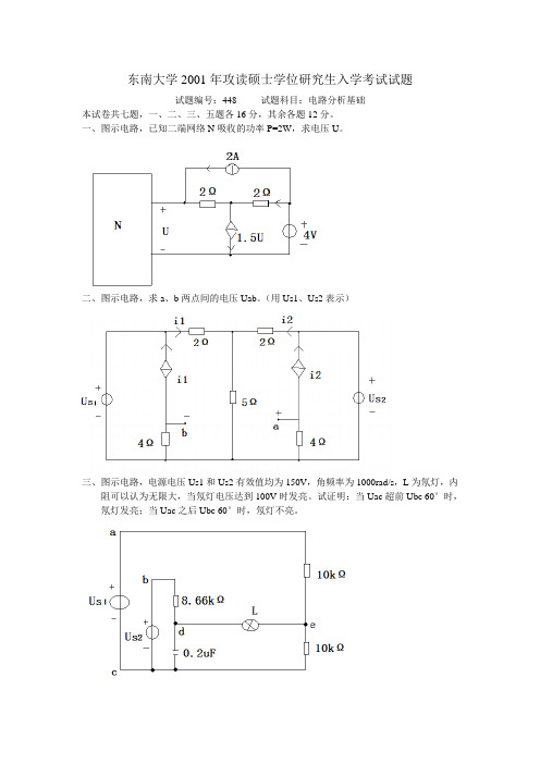
东南大学2001年攻读硕士学位研究生入学考试试题试题编号:448 试题科目:电路分析基础本试卷共七题,一、二、三、五题各16分,其余各题12分。
一、图示电路,已知二端网络N吸收的功率P=2W,求电压U。
二、图示电路,求a、b两点间的电压Uab。
(用Us1、Us2表示)三、图示电路,电源电压Us1和Us2有效值均为150V,角频率为1000rad/s,L为氖灯,内阻可以认为无限大,当氖灯电压达到100V时发亮。
试证明:当Uac超前Ubc 60°时,氖灯发亮;当Uac之后Ubc 60°时,氖灯不亮。
四、图示电路,已知A t t i s )30cos(2)( +=,t t U s 3cos 23)(1=V ,Us2=3V ,R1=R3=1Ω,R2=2Ω,L1=1/3 H ,L2=8/3 H, C=1/3 F 。
求电容两端电压Uc ,is 两端电压U 。
五、图示电路,初始状态不详,当Us1(t )=ε(t )V ,Us2=2t cos ε(t )V 时,A t t e t i t L )()]4/cos(231[)(επ-+-=-。
求:1、在相同的初始状态下,Us1(t )=ε(t ),Us2(t )=0时,)(t i L =?2、在相同的初始状态下,Us1(t )=0,Us2(t )=0时,)(t i L =?六、图示电路,已知Us (t )=16cos t V ,t<0时,K 断开,电路已达稳态。
t=0时,K 闭合,求t>=0时的电流i (t )。
七、已知N为线性无源结构对称的电阻网络,已测得图(a)电路的输入导纳为Y a,图(b)电路的输入导纳为Yb,试求网络的Y参数。
(a)(b)。
东南大学(934)电路考试真题(回忆版)及参考答案
4.1.1 东南大学(934)电路2008年硕士研究生入学考试试题参考答案4.2 东南大学(934)电路2009年硕士研究生入学考试试题及答案4.2.1 东南大学(934)电路2009年硕士研究生入学考试试题参考答案4.3 东南大学(934)电路2010年硕士研究生入学考试试题及答案4.3.1 东南大学(934)电路2010年硕士研究生入学考试试题参考答案4.4 东南大学(934)电路2013年硕士研究生入学考试试题(回忆版)1.网络问题,已知某一支路电流,求电压,把三角形化成星形用节点电压(好像是07 或年真题)2.黑箱问题,给了一个条件求电阻为何值事功率最大,也就是求戴维南等效,根据已知条件算出开路电压与电阻关系即可3 网络问题,已知某一电阻功率,和两个电源的变换,求支路电压,应用叠加定理算出,注意正负两个值4 功率补偿问题,以前的真题5 放大器问题正弦稳态电路6 动态电路问题已知电压电流响应求电容,和到达三分之一能量时的时间,以前的真题7 黑箱问题,求响应,10 年真题8 正弦稳态问题+理想变压器已知两电表读数相同,注意到并联谐振即可9 非线性电路问题求静态工作点时电容相当于开路10 非正弦周期问题求某电压和功率,叠加定理大题1。
陈燕书上的原题,应该也是04 年大连交通的题2。
03 年真题3.一阶电路问题,换路后右边是电感组成的一阶电路,左边由以右您所下载的资料来源于 考研资料下载中心获取更多考研资料,请访问边电感电流为受控辆的受控电压源直接接在电容两端,求某支路电流,计算时注意冲击响应4 三相电路问题,第一问求线电压,第二问是A 相故障求B,C 相电流5 非正弦周期问题,叠加定理,难点在于那个空心变压器,先戴维南化简下会简化计算6 三相电路的非对称电路,1 求线电压2 求开关断开时由来电感和三个电阻组成的回路组成的网络,应用磁链守恒和拉普拉斯都可以,和04 年真题三相电路有点像,比那题简单点。
《东南大学电子技术基础2007-2012年考研真题及答案解析》
地电压 uc1 , uc2 。(16 分)
二、电路图如图所示 已知VT1的 gm 0.7mS ,VT 2 的 40 , rbe 1k ,试:
(1)写出各触发器 CP 信号的方程和驱动方程; (2)写出电路的状态方程; (3)画出状态表及状态图; (4)画出电路的时序图。(20 分)
《东南大学电子技术基础历年考研真题及答案解析》
5 / 102
九、试用集成数据选择器 74LS151 实现逻辑功能
L A, B,C, D m3, 4,5,8,9,10,14,15
(1)画出其微变等效电路; (2)求电路的电压放大倍数; (3)求电路的输入电阻; (4)分析电容 C 的作用。(18 分)
《东南大学电子技术基础历年考研真题及答案解析》
2 / 102
三、电路图如图所示, VT1、VT 2 管的饱和压降 UCES 1V ,试:
(1)简述电路的工作原理;
(2)计算最大输出功率 Pomax ; (3)确定VT1、VT 2 管的 PCM ,UBRCEO , ICM 至少应选多少? (4)若测得负载 RL 上的电压有效值为 10V,试求输出功率 Po 、电源提供功率 PV 、效 率 以及单管管耗 PT1 ,此时的输入信号的有效值。(18 分)
《东南大学电子技术基础历年考研真题及答案解析》
1 / 102
Ⅰ 历年考研真题试卷 东南大学 2007 年招收攻读硕士学位研究生入学考试试卷
请考生注意:试题解答务请考生做在专用“答题纸”上!
电力电子技术考研必备题库与答案

电力电子技术试题库答案来源:欧阳陶昱的日志电力电子技术试题库答案一、填空题(每空1分,共20分)1、电力电子技术是利用(电力电子器件)对电能进行(控制、转换和传输)的技术.3电力电子技术研究的对象是(电力电子器件的应用)、(电力电子电路的电能变换原理)和电力电子装置的开发与应用。
.1957年(美国通用电气(GE)公司)研制出第一只晶闸管,它标志着(电力电子技术)的诞生。
6、电力二极管的主要类型有(普通二极管),(快恢复二极管)和肖特基二极管。
7、电力二极管的主要类型有普通二极管,(快恢复二极管)和(肖特基二极管)。
8、晶闸管是一种既具有(开关作用),又具有(整流作用)的大功率半导体器件。
9、晶闸管有三个电极,分别是(阳极),(阴极)和门极或栅极。
10、晶闸管有三个电极,分别是阳极,(阴极)和(门极或栅极)。
11、晶闸管的正向特性又有(阻断状态)和(导通状态)之分。
12、半控型电力电子器件控制极只能控制器件的(导通),而不能控制器件的(关断)。
13、电流的波形系数Kf指(电流有效值)和(电流平均值)比值。
14、电力晶体管是一种(耐高压)、(大电流)的双极型晶体管。
15、电力晶体管的安全工作区分为(正偏安全工作区)和(反偏安全工作区)。
16、双向晶闸管有两个(主)电极和一个(门)极。
17、双向晶闸管有(I+触发方式),(I-触发),III+触发和III-触发。
18、IGBT的保护有(过电流保护),过电压保护和(过热保护)。
19、降压变换电路的输出电压与输入电压的关系为(Uo=DUd),升压变换电路的输出电压与输入电压的关系为(Uo=Ud/(1-D))。
20、全控型电力电子器件控制极既能控制器件的(导通),也不能控制器件的(关断)。
21、电力器件的换流方式有(器件换流),(电网换流),负载换流和脉冲换流。
22、负载换流式逆变电路分为(并联谐振式),(串联谐振式)。
23、按照稳压控制方式,直流变换电路可分为(脉冲宽度调制)和(脉冲频率调制)。
电力电子考试题库-(含答案)

电力电子考试题库-(含答案)一、填空(每空1分),1、请在正确的空格内标出下面元件的简称:评計亡円斤*电力晶体管GTR ;图形符号为___________ ;' " '可关断晶闸管GTO ;图形符号为___________ ;功率场效应晶体管.MOSFET;图形符号为__________ ;绝缘栅双极型晶体管_IGBT 图形符号为__________ ;IGBT是一MOSFET和—GTR的复合管。
2、晶闸管对触发脉冲的要求是要有足够的驱动功率、触发脉冲前沿要陡幅值要高 _和_触发脉冲要与晶闸管阳极电压同步。
3、多个晶闸管相并联时必须考虑均流的问题,解决的方法是串专用均流电抗器。
4、在电流型逆变器中,输出电压波形为一正弦波「输出电流波形为—方波_。
5、型号为KS100-8的元件表示—双向晶闸管—晶闸管、它的额定电压为_800V_伏、额定有效电流为_ 100A_。
6、180°导电型三相桥式逆变电路,晶闸管换相是在_同一桥臂的上、下二个元件之间进行;而1200导电型三相桥式逆变电路,晶闸管换相是在一不同桥臂上的元件之间进行的。
7、当温度降低时,晶闸管的触发电流会一增加_、正反向漏电流会—下降一;当温度升高时,晶闸管的触发电流会一下降「正反向漏电流会一增加?。
& 在有环流逆变系统中,环流指的是只流经_逆变电源_、_逆变桥而不流经一负载一的电流。
环流可在电路中加_电抗器_来限制。
为了减小环流一般采控用控制角a _大于B的工作方式。
9、常用的过电流保护措施有快速熔断器—、串进线电抗器、接入直流快速开关_、控制快速移相使输出电压下降。
(写出四种即可)门极G接负—电压,T2接_正_电压。
川+触发:第一阳极T1接_负电压,第二阳极T2接正_ 电压;门极G接正电压,T2接_负_电压。
川-触发:第一阳极T1接—负电压,第二阳极T2接—正电压;门极G接—负电压,T2接—正_电压。
电力电子研究生试题(1)

一、试设计采用IGBT模块和微机(或DSP等)构成的SPWM三相逆变系统,要求在100HZ/150HZ下调制,输出电压、电流和频率可调,试画出主电路和控制电路的硬件框图和软件流程图,并给出设计思路。
并要求画出u和uv的波形。
设计思想:本方案以电压型逆变器(VSI)作为主工作电路,该逆变器为基于自关断器件IGBT的脉宽调制SPWM逆变器。
直流端为一大电容,并由三相整流桥为其提供能量,R为泻放电阻,L为指示灯。
VSI的输出端接有输出滤波器,以此来滤除开关器件通断造成的高频毛刺,从而获得较为平滑的正弦波。
当载波幅值一定时,调制波的幅值改变输出电压幅值(输出电压限值由直流电压决定),载波频率设定为150Hz,调制波的频率为100HZ,直接决定输出电压频率。
注意事项:(1)必须采用输出滤波器,否则很难得到较为平滑的正弦波;(2)泻放电阻当整流断路器关断时泄放直流侧电容上的能量;(3)为了使输出电压的幅值和频率稳固须采用闭环控制。
逆变器主电路框图三相桥式逆变器硬件电路如下:三相桥式逆变器控制电路框图SPWM脉宽调制我们采用改进规则采样法的PWM调制方法改进规则采样法设三角波的周期为T ,在相邻两个三角波负峰时刻t i 和t i +T 对调制信号采样而得到C 点和D 点,过C 点和D 点作一直线和三角波分别交于A 点和B 点,在A 点的时刻t 1和B 点的时刻t 2控制功率开关器件的通断。
每个周期的采样时刻t i 、三角波的周期T 和幅值H 都是确定的,设调制信号在C 点和D 点的值分别为s 1和s 2,则线段CD 的方程为121s s Ts s t t i -=-- 三角波两腰的方程分别为HTH S t t i 4=+-HTH S T t t i 4-=+--分别联立方程上面三个方程,可解得t1和t2分别为i t s s H s H T t +-++=21114)(i t s s H s H T t +-+-=12124)3(这样,就得到了PWM 控制信号的脉宽数据。
东南大学2005年研究生考试《电工基础》试题及解析

河海大学: 2006 年材料力学试题,试题解析 2006 年水力学试题,试题解析
南京邮电大学: 2005 年通信系统原理试题,试题解析
南京理工大学:
恩波翔高,考研专业课培训专家
2005 年分析化学试题,试题分析 2005 年机械原理试题,试题分析 2006 年无机化学试题,试题分析 2006 年电子技术基础试题,试题分析
图 14
4、图 14 所示三相电路中,UAN、UBN、UCN 为对称三相电源,设 UAN=220<0°V,计算电流 iLO. u2 u>0
5、图 15 所示电路中,电压控制型非线性电阻的伏安关系为 i1=g1(u)= 0 u<0
LS=8A,i(t)=0.5Sin(t)A,用小信号分析法计算 u, i1,i2.
恩波翔高,考研专业课培训专家
图 15
图 16
6、作出图 16 所示电路的复频域电路模型,计算其零状态响应 u(t)。
一,
1,_ 9 ×10⁻⁵ J
2,50W 3,20V 4,u=2i
5, 3Ω
_ 5Ω
6, 3 + 251.25 3W
2005 年真题解析
恩波翔高,考研专业课培训专家
7,_-1.5_
2005 年文学试题,试题解析 2005 年法理学试题,试题解析 2005 年政治学试题,试题解析 2005 年经济学试题,试题解析 2005 年新闻传播史论试题,试题解析 2005 年行政管理学试题,试题解析
东南大学: 2005 年机械原理试题,试题解析 2005 年电工基础试题,试题解析 2005 年现代管理学试题,试题解析 2005 年工程力学试题,试题解析 2005 年结构力学试题,试题解析
东南大学 东大 01-04年电子线路基础 考研真题及答案解析
布丁考研网,在读学长提供高参考价值的复习资料
布丁考研网,在读学长提供高参考价值的复习资料
布丁考研网,在读学长提供高参考价值的复习资料
布丁考研网,在读学长提供高参考价值的复习资料
布丁考研网,在读学长提供高参考价值的复习资料
布丁考研网,在读学长提供高参考价值的复习资料
布丁考研网,在读学长提供高参考价值的复习资料
布丁考研网,在读学长提供高参考价值的复习资料
布丁考研网,在读学长提供高参考价值的复习资料
布丁考研网,在读学长提供高参考价值的复习资料
布丁考研网,在读学长提供高参考价值的复习资料
布丁考研网,在读学长提供高参考价值的复习资料
布丁考研网,在读学长提供高参考价值的复习资料
布丁考研网,在读学长提供高参考价值的复习资料
东南大学电力电子

全日制硕士研究生入学复试554专业综合之<<电力电子技术>>课程考试大纲一、考试目的《电力电子技术》作为电气工程硕士学位入学复试的专业课复试课程,其目的是考察考生是否电力电子的基本功底和电力电子电路的理解分析能力。
二、考试基本要求掌握电力电子技术的定义、各种电力电子器件的特性和使用方法、电力变换的四种基本类型,熟悉典型电力电子电路的拓扑结构,并掌握其工作原理、控制方法及计算方法。
熟悉各种电力电子装置的应用。
考察考生是否具有电力电子的基本功底和对电力电子电路的理解分析能力。
三、考试内容范围1、电力电子器件了解电力电子器件的特征;新型电力电子器件和功率模块和功率集成电路;由电力电子器件所构成的系统。
掌握电力电子器件的分类;电力二极管、晶闸管及基本的全控型器件(GTO、GTR、MOSFET 及IGBT)的结构、电气图形符号、工作原理、基本特性、主要参数;器件的保护电路、缓冲电路及驱动电路的工作原理;晶闸管的基本保护措施及电力电子器件的串并联特点。
重点掌握晶闸管的结构、工作原理、主要参数(电压额定、电流额定)的选择计算。
2、整流电路了解各种整流电路的结构、移相范围,有源逆变失败的原因及由晶闸管同步相位控制驱动的电路;可逆直流拖动系统。
掌握变流电路在整流和逆变工作状态时的原理及波形分析;电路中各物理量的计算;有源逆变的条件;变压器漏感对整流电路的影响。
重点掌握单相和三相半波整流电路及单相和三相全控桥整流电路在不同性质的负载下的波形分析及计算。
3、逆变电路了解单相全桥电压型逆变电路的移相调压方式、多相多重逆变电路及多电平逆变电路。
掌握无源逆变电路的工作原理及换流方式;三相逆变电路的工作特点。
重点掌握电压型和电流型逆变电路的特点;单相半桥和全桥电压型逆变电路的结构、工作原理、输出波形及不同时间段各器件的工作状态的分析;单相电流型逆变电路(并联谐振逆变电路)的结构、工作原理及换流过程的分析。
电力电子技术考试模拟题含参考答案
电力电子技术考试模拟题含参考答案一、单选题(共25题,每题1分,共25分)1.目前,在中小型变频器中普遍采用的电力电子器件是()。
A、SCRB、GTOC、MOSFETD、IGBT正确答案:D2.电阻性负载三相半波可控整流电路中,控制角的范围是()A、30°~150B、0°~120°C、0°~150°D、15°~125°正确答案:C3.三相全波可控整流电路电阻性负载中,控制角的最大移相范围是()。
A、90°B、120°C、180°D、150°正确答案:B4.具有自关断能力的电力半导体器件称为()A、不控型器件B、全控型器件C、半控型器件D、触发型器件正确答案:B5.可实现有源逆变的电路为()。
A、单相全控桥接续流二极管电路B、单相半控桥整流电路C、三相半波可控整流电路D、三相半控桥整流桥电路正确答案:C6.1957年美国通用电气(GE)公司研制出第一只(),它标志着电力电子技术的诞生。
A、电子管B、晶闸管C、MOSFETD、IGBT正确答案:B7.已经导通的晶闸管的可被关断的条件是流过晶闸管的电流()A、减小至维持电流以下B、减小至擎住电流以下C、减小至门极触发电流以下D、减小至5A以下正确答案:A8.IGBT是一个复合型的器件,它是()A、GTR驱动的MOSFETB、MOSFET驱动的GTRC、MOSFET驱动的晶闸管D、MOSFET驱动的GTO正确答案:B9.为了防止逆变失败,最小逆变角限制为()。
A、300~350B、200~250C、400~450D、100~150正确答案:A10.降压斩波电路中,已知电源电压Ud=16V,负载电压Uo=12V,斩波周期T=4ms,则开通时Ton=()A、4msB、1msC、2msD、3ms正确答案:D11.单相半波可控整流电阻性负载电路中,控制角α的最大移相范围是()A、150°B、120°C、90°D、180°正确答案:D12.电阻性负载三相半波可控整流电路中,控制角的范围是()。
东南大学954电路电气工程考研真题及答案剖析 汇编
3、东南大学《电路基础》本科教学大纲
东大954电路虽然考查知识点不多,但是试题很有难度,计算量较大,建议早点复习,复习时参考东南大学本科生《电路基础》教学大纲和东南大学954电路《考试大纲》。
4、2016年校内答疑知识点
含2016年校内答疑老师透露的知识点,对想考研省力的学生很有帮助!
三、东南大学《电路(电气工程)》考研复习题
1、《电路基础》课后习题详解答案
黄学良的电路课本的习题答案详解(考过原题,而且是本校用书,有一定参考价值)
2、电路考研大串讲习题答案
电路大串讲习题答案详解(综合985高校的考研题目,经典之极,助你达到新的高度!)
四、赠送资料(电子版,发邮箱)
第一部分:专业课
第二部分:公共课
以下为截图及预览:
2015年考研真题:
2014年考研真题:
2015年真题答案:
2014年真题答案:
考研复习笔记:
考研复习题:。
2014东南大学954电路考研真题与解析

历年考研真题试卷东南大学2007年招收硕士学位研究生入学考试试卷请考生注意:试题解答务请考生做在专用“答题纸”上!做在其他答题纸上或试卷上的解答将被视为无效答题,不予评分。
科目代码:954 科目名称:电路(电路工程)一、填空题(每题6分,共60分)1.图1所示电路中,U ab = V 。
图12.图2所示电路中,A i 6.0=。
则=sU V 。
图23.图3所示电路,在零状态响应时,出现振荡的条件为 。
图34.图4所示电路中,已知I=3A 。
则网络A 所吸收的功率= W ,电流源所发出的功率= W 。
图45.图5所示正弦稳态电路中,两电源频率相同,且SU •=︒∠020V ,︒∠=•05SIV ,则图中开路电压•U = (V)。
图56.图6所示电路中,已知I 1=I 2=3A ,U S1=U S2=U S3=5V ,则I 3= A 。
图67.图7所示的三相电路中,已知对称三相电源的线电压是U ,则当开关K 打开时,图中的电压U AN = V ,U BN = V 。
图78.图8所示的稳态电路中,已知i S (t)=A t )30100cos(29︒+。
则负载最佳匹配时,阻抗Z= ,此时获得的最大功率P= 。
图89.已知某一阶RC 电路的全响应U C (t)=(4-3e -3t )V 。
若初始状态不变而输入增加至原来的3倍,则此时电路的全响应U C (t)= 。
10.如图9所示电路,开关闭合以前电路已经稳定。
当t=0时刻开关闭合,则S 闭合后的电容电压u C (t)= 。
图9二、计算题(每题15分,共90分)1.如图10所示电路中,已知电流源I S 发出的功率为2mW ,求I S 的值。
图102.如图11所示电路,求各支路电流以及各独立电源、受控源的功率。
图113.如图12所示电路为正弦稳态电路,已知11=I A 。
(1)求电流I ;(2)电流源S I •发出的功率P 。
图124.如图13所示电路,在t=0时,将u1(t)=5V的电压源接入,求零状态响应u2(2)。
东南大学电工电子学试卷

共 45 页 第 1 页东 南 大 学 考 试 卷(A 卷)课程名称电工学 考试学期 11-12-2得分适用专业 机械工程及自动化 考试形式 闭卷 考试时间长度120分钟1)Birds routinely land and relax on power lines whichcarry tens of thousands of volts of electricity. Explain why these birds do not get electrocuted. (6 pts)The resistance of the air is too large for current to flow from the line to the bird to the ground.Alternately, the resistance is too large for current to divert from the wire, into the bird, and then back into the wire. It is not because of wire insulation. Birds could land on uninsulated wires just fine.6 pts for right answer. 1 pt for something vaguely correct.2) Suppose your car battery is dead, and you need to charge it using another car’s battery. You have a pair of cables 电缆which you can use to connect the terminals终端of the batteries. In order to charge your car battery, should you connect the same terminals (positive of one battery to the positive of the other, and the same with the negative) or the opposite terminals (positive of one battery to the negative of the other battery)? Why did you choose this configuration配置;结构? (6 pts)First note that real batteries have internal内部的resistance, so the universe领域will not explode爆炸if you directly connect two car batteries.Next, if the opposite terminals are connected, then P=VI and common sense tells us that both batteries will be supplying power, and the internal resistances will be consuming消耗power, so clearly no power is being delivered 递送by either battery. If the same terminals are connected,共45 页第 2 页then we can see that if one battery is of a higher voltage than the other, it will provide power to theother battery. Key to this realization实现is to know that battery voltages drop下降;终止as the battery is depleted耗尽的.6 pts for right answer. 2 pts if you try to say there is no current if two batteries are connected + to+ because voltage sources are perfectly balanced.3) A standard procedure for testing the internal resistance of a battery is the “dual双重的pulse脉冲” test. We first attach an ideal 5 mA current source between the terminals of the battery, so that current flows in the usual direction (positive to negative), and measure the voltage across the battery terminals. We then remove the 5 mA source, and attach an ideal 505 mA current source instead,and again measure the battery terminals. (6 pts)共45 页第 3 页i.Suppose that we find a 1.485V voltage with the 5 mA source, and a 1.385 with the 505 mA source, what is the internal resistance?Easy way to solve these is to subtract减去;扣掉 2nd from first, giving, or .3 pts for right answer. 2 pts if sign error or algebra 代数学mistake.ii. Assuming the battery is perfectly linear 线型的(i.e. accurately modeled 模式化;被效仿by a Thevenin 戴维宁equivalent), is it possible to find the voltage provided by the battery with no load attachedusing the data above? If so, what is it? If not, why not?共45 页第 4 页Plug塞住;用插头将与电源接通 in to one of our equations above, e.g., giving , or finally. If you did it with the current source the other way, you should still have gotten 1.486V.3 pts for right answer.Find the Thevenin or Norton equivalent circuit model.(12 pts ).共45 页第 5 页(6 pts )(6 pts )Find the Voltage v and the currents i1 and i2 for the circuit shown below. (10 pts )共45 页第 6 页SolutionLabel标注 the meshes;网状物:Since i3=2 it is not a variable.Writing KVL around the first mesh:24*(i2-i3) + 12*i1 = 0Writing KVL around the second mesh:12*i2 + 6*(i2 –i3) = 0Substituting代替,取代 for i3 and rearranging 36*i1 = 4818*i2 = 12共45 页第7 页Namelyi1 = 4/3 Ai2 = 2/3A7. Find the current i for the circuit shown below (10 pts )SolutionZeroing the 1A source gives共45 页第8 页By the current division principle, the contribution of the 2A source to i1 is2*(-1/30) / (1/30+1/5) = -2/7A.Zeroing the 2A source givesBy the current division principle, the contribution of the 1A source to i1 is1*(1/15)/(1/15+1/20) = 4/7A.Hence i1 = 4/7-2/7 = 2/7A.共45 页第9 页Find the Thevenin and Norton equivalent circuits across terminals a and b for the following circuitWith an open circuit across terminals a and b the current through the 20 resistor must be 0.5ix and the voltage across it is then 10ix. ByKVL we also get30V = 5ix + 10ixSo ix = 2A and we calculateVTH = 10ix = 20VTo find RTH we zero the independent独立的 source to get the circuit in Figure 4.We wish to determine what resistance this circuit isequivalent 等价的to across共45 页第10 页the terminals a and b. One way to do this is to imagine connecting anindependent voltage source of voltage VS across the terminals and findingthe current drawn from this voltage source. We therefore consider thecircuit in Figure 5.KVL gives−5Ωix = VS → ix = −VS/5Ω A (1)KVL also gives20Ωi1 = VS → i1 =VS/20 Ω (2)KCL givesi = i1 + 0.5ix − ix = i1 − 0.5ix (3)共45 页第11 页Plugging (1) and (2) into (3) yieldsi =VS/20Ω+VS/10Ω=3VS/20ΩEventually,RTH =VS/i=20/3 ΩThe Thevenin equivalent circuit is depicted描述; in Figure 6.From this we get the Norton equivalent circuit in Figure 7 where we usedWe could have also determined IN by applying a short circuit across theterminals a and b and computing 计算;处理the current through the short circuit短路.This involves analyzing the circuit in Figure 8. Here wehave by KVL共45 页第12 页5ix = 30V → ix = 6AThis gives, by KCLi = ix − 0.5ix = 0.5ix = 3Awhich matches the earlier calculation计算;估计.Suppose that v1(t) = 80 cos (ωt) and v2(t) = 60 sin (ωt). Use phasors相量 to reduce the sum vs(t) =v1(t) + v2(t) to a single 单一的term of the form Vm cos (ωt +θ). Draw a phasor diagram, showing V1, V2, and Vs. State the phase relationships between each pair of these phasors. (16共45 页第13 页pts )The phasor corresponding tov1(t) = 80 cos (ωt)isV1 = 80∠0 = 80Equivalently, we get forv2(t) = 60 sin (ωt) + 60 cos (ωt −π/2)the phasorV2 = 60∠−π/2 = −j60To find the sum using phasors we add the complex numbers which yieldsV = V1 + V2 = 80 − j60 = 100e−j arctan 3/4This corresponds符合,一致 to the time signalvs(t) = 100 cos (ωt − jarctan3/4)The phasor diagram is depicted描述 in Figure 2.Note that V1 leads V2 by π/2 and leads Vs by arctan反正切 ( 4/3 ).共45 页第14 页Find an expression 表达式for v(t) of the form Vm cos (ωt +θ) when v(t) = v1(t) + v2(t) + v3(t) + v4(t) withv1(t) = 20 sin (ωt)v2(t) = 20 cos (ωt +π/6)v3(t) = 20 sin (ωt +π/3)v4(t) = −10 cos (ωt)Use phasors. (6 pts )Solution:The phasors corresponding 相应的to each component 成分;组件;[电子] 元件signal are given in Table表格 1. The complex number equivalent复数等效to each phasor is given as well.共45 页第15 页Adding all complex numbers giveswhich corresponds to the phasorwhich can be transformed变形 into the time signalFind the complex impedance阻抗 in polar form 点斜式极坐标形式极形式of the network shown below for ω = 10001/s , ω= 20001/s ,and ω = 40001/s . (6 pts )共45 页第16 页(5 pts)Both capacitors电容器 and inductors电感器 can be used to store energy for use later. Capacitors, though, are far more popular for energy storage than inductors, because they are easier to keep charged带电荷的带电的. In lab, for example, you can easily connect up a capacitor to a battery, disconnect it from the source, carry it around in your pocket to grab lunch午餐, go back to lab, and then find that it's still holding a charge even after a long time. Explain why this is relatively difficult with inductors.共45 页第17 页(5 pts) If you've ever had the batteries on a flash li ght闪光灯;手电筒 run out,you know that as soon as the ligh t starts dimming调光;变暗,your battery will very soon be dead.This is because a battery supplies its maximum vo ltage峰点电压 until right before it is depleted耗尽的.On t he axis 坐标轴on the left,I have plotted标绘的 the brightn ess亮度辉度 of a battery powered flashlight over the lif e of the battery.We can also power a flashlight using共45 页第18 页a capacitor.Assuming the brightness of a bulb 电灯泡is p roportional比例的 to the voltage across it,on the right axis,draw (qualitatively定性地) the brightness vs. Time for a capacitor powered flashlight.Draw so that bright ness is 1 at time=0,and has dropped to at least 0.1 by time=1.We just want the shape形状,not necessarily the exact values.c) (5 pts) A student is not satisfied with the amount of共45 页第19 页energy stored in his one-capacitor circuit. He wants to store more energy, so puts 10 capacitors in series串联 and charges them with a single voltage source. Is this a good idea? Why or why not?Find the Thevenin equivalent 戴维南定理of the circuit电路below at the two terminals on the far right:共45 页第20 页e) Find the Thevenin equivalent of the circuit below between terminals and [Think about the various algorithms算法 we’ve used to find Thevenin equivalents.If you get stuck被困住了,complete the rest of these tricky 棘手的复杂的problem and come back to this one and maybe some inspiration will reach you]:共45 页第21 页共45 页第22 页For the circuits below, please find expressions for the specified voltage表达式指定的电压over the indicated time 表示时间ranges in terms of the circuit parameters电路参数. Plot 绘图 the waveform 波形图on the provided axes轴线, and clearly identify. 确定 the key parameters参数 in your graph图表. (3A) Consider the circuit of Fig. 4. The switch is open for t <0, closed for 0≤t < t1, and open for t ≥t1, where t1 = 3RC. Find and plot the voltage v C (t).共45 页第23 页(3B) Consider the circuit of Figure 5, in which > -1.共45 页第24 页The switch is open for t <0, and closed for t 0. vC(0-) = V0. Find and plot the voltage v1(t).共45 页第25 页The circuit shown in Figure 4 has been at rest with theswitch open for a long time. At t = O the switch is closed.共45 页第26 页Sketch 素描;略图;梗概the current ic集成电路 through the capacitor for t > O on the axes below. Using the circuit parameters R1, R2, C, and Vo,indicate on your sketch (i) the initial value初始值 ic(Ot), (ii) the final value ic(oo), and (iii) the time constant时间常数.共45 页第27 页Problem 1F: 5 pointsThe capacitor in the circuit in Figure 6 has an initial初始最初的voltage V O on its terminals at t =0−when a step of voltage Vu(t) is applied at t = 0. Find an expression for the voltage across the capacitor v C for t> 0.共45 页第28 页Consider the current divider circuit分流电路 shown below:共45 页第29 页1a. How many branches分支 are there in the circuit?1b. How many nodes节点 are there in the circuit?2. Derive an expression派生一个表达式 for the output current 输出电流(Iout, shown above) as a function of theinput current (Iin) and the two resistors (R1 and R2). Use any technique you’d like.3. How should the resistors be chosen such that twice as much current flows throughR1 compared to R2?4. Using the equation 方程等式you obtained in #2, show what happens to Iout输出电流 if R2 is replacedwith a short circuit (i.e. R2 = 0). Repeat if R2 is replaced with an open circuit.(think about what R2 should be replaced with here) Now suppose the following values are used: Iin = 3 A, R1= 5 , R2 = 20 , and we wish to find the Thevenin共45 页第30 页equivalent circuit across the two indicated terminals below:5. Find Voc and Isc across the two terminals indicated on the circuit.6. Draw the Thevenin equivalent circuit for the two terminals indicated above.7. Suppose a load is now attached across the two terminals of the Theveninequivalent circuit:a. Write an equation for I in terms of V.b. Sketch the IV characterstics伏安特性. Use I as the“y-axis Y轴” and V as the“x-axis”. Label标注all relevant points相关点.共45 页第31 页8. Suppose the load has an IV characteristic given as follows:a. What are the values of I and V if the load is attached to the Thevenin equivalent circuit ] 等效电路?b. Looking at the IV characteristic, what is the load? (describe the load as much as you can)For problems 9 through 12, consider the following circuit:9. Using KVL and mesh analysis, write down the equations needed to solve the circuit. Convert转变the resistor voltages into currents.10. The dependent source requires one additional equat共45 页第32 页ion附加方程to be generated产生. Write down that equation by looking at the 3 resistor.11. Solve the equations simultaneously同时地to determine the two mesh currents网孔电流.12. To check your answer, confirm确认that power is conserved 守恒in the circuit. Find the power dissipated浪费的in each resistor. Find the power generated生成的(or dissipated in each source). Be clear in your answers whether power is being generated or dissipated in each circuit element. For problems 1–7, consider the following circuit:1. Find the transfer转移function, i.e. Vout输出电压()/Vin(), in terms of R, L, and .2. What is the magnitude大小of the transfer function传递函数, i.e. | H() |, in dB?3a. What is | H() | equal to (in dB) for very low共45 页第33 页frequencies频率?3b. What happens to | H() | at high frequencies? What kind of a filter滤波器do we have here?4. Derive the equation for the break frequency推导出方程为截止频率. The break frequency is definedas the frequency where | H() | = –3.0103 dB.5. Sketch the magnitude Bode波特图plot for this filter滤波器. Label标注all critical points andslopes. Show how you obtained the value for any non-zero slopes零斜坡.6. Suppose R = 1 , L = 2 H, and Vin = 3 cos(5t + 30o). Find Vout(t).7. Draw a phasor diagram, indicating the voltage and current phasors of all thecircuit elements电路参量.For problems 8–12, consider the following circuit:共45 页第34 页8a. Find the current that appears on the output side ofthe transformer变压器.8b. What is the voltage that appears across the capacitor. (phasor form is acceptable,assume an angular frequency角频率of 1 rad/s)9. Find the voltage that appears on each side of the transformer.10. Find the voltage that appears across the current source.11. Replace the transformer and input circuitry with an equivalent current sourceand inductor. In other words, draw a circuit which will have a current source,an inductor, and a 3 F capacitor all in series. Label the values for the current source and the inductor.Check your answer to #11 by comparing the amount of power共45 页第35 页generated by the currentsource in each circuit.12. Find the amount of power generated by the current source in the new circuit.Compare this with the amount of power generated by the current source in theoriginal circuit原电路 (they should be the same)For problems 4–7, consider the following circuit:4. Find the transfer function, i.e. Vout ()/Vin (), in terms of R, L, and (or f).5. What is the magnitude of the transfer function, i.e. | H() |?共45 页第36 页6. What is | H() | equal to for very low frequencies? For very high frequencies?What happens at resonance谐振? (i.e. = o =LC1) What kind of a filter滤波器do we have here?7. Sketch the magnitude Bode plot for this filter. Label all critical points andslopes斜率. Use R = 2 , L =41H, and C =81F. Show how you obtained the valuefor any non-zero slopes.In order to measure the voltage across a resistor in a circuit, a voltmeter电压表is used.Although we assume an ideal voltmeter in most cases, a real voltmeter has a finite有限的resistance (R3) which can have an effect on your circuit. Consider the followingmeasurement on a voltage divider分配共45 页第37 页Vin, R1, and R2 are just the standard elements of a voltage divider.1a. How many nodes are there in the circuit?1b. How many meshes are there in the circuit?2. Write a KCL equation at node A. Convert the currents into voltages.3. Solve the equation for Vout, so that you have an equation for Vout based onVin, R1, R2, and R3.4. Show that as R3 approaches infinity无限大(i.e. R3 ), you get the standardequation for a voltage divider.For problems 5 through 11, consider the following circuit:共45 页第38 页Find the Norton equivalent circuit, as follows:5. Short circuit the two terminals and redraw the circuit without the 2 resistor.Explain why the 2 resistor can be dropped from the circuit.放弃了电路6. Use node analysis to find Isc. (You will need to come up with one additionalequation to eliminate消除ix and get a numerical数字的answer) 7. Now consider the circuit when the two terminals are open circuited. Using meshanalysis, find ix under these conditions.8. Using your results from #7 (or using node analysis, which will take more time),find Voc, the voltage across the two terminals in an open circuit condition.共45 页第39 页9. Confirm that power is conserved in the circuit under open-circuit conditions.Find the power dissipated in each resistor. Find the power generated (ordissipated in each source). Be clear in your answers whether power is beinggenerated or dissipated in each circuit element.10a. Draw the Norton equivalent circuit. Label values for all circuit elements.10b. Draw the Thevenin equivalent circuit. (Note: you already have everything youneed)11a. Assume that a circuit element (that draws some current I and has somevoltage drop V) is attached to the terminals of the Norton equivalent circuit.Using KCL, write an equation for I in terms of V.11b. Graph the IV relationship (i.e. the load line). Use I as the “y-axis” and V as the共45 页第40 页“x-axis”. Label all relevant points.For problems 1–5, consider the following circuit:Use Vin = 100 v, R1 = 1000 , R2 = 250 , R3 = 1000 , and C = 1 F. At t = 0, theswitch is moved down, disconnecting R1 and connecting R2 to the circuit. We want to find the voltage v(t), and current i(t), across the capacitor as a function of time. 1a. Redraw the circuit, showing how the circuit looks just before the switch ismoved. Assume a long time has already elapsed before the switch is moved.1b. What is the continuity连续性condition for this circuit共45 页第41 页at t = 0?2. Using the circuit generated in #1a, find v(0–) and i(0–)3a. Find v(). Explain how you get this result.3b. Write a KCL equation for the circuit after the switch as been moved at t = 0.Convert the currents into voltages. (you should end up with a first-orderdifferential equation for v(t))4a. What form should the solution for v(t) take?4b. Substitute替代this solution into the differential equation generated in #3b. Use theresults of the substitution, along with the results for #1b and #2 to find all theconstants defined for v(t). (Clearly show your work) 5. Sketch curves of i(t) and v(t) as a function of time (t ). Indicate allcritical and asymptotic values.For problems 6–10, consider the following second-order共45 页第42 页circuit:The switch is opened at t = 0. The goal is to find the current through the inductor, i(t).6a. Assume that the switch has been closed for a long period of time. Find i(0–).6b. What should i(0+) be? Explain.7a. Find i(). Explain how you get this result. Draw the corresponding相应的circuitat this steady state condition.7b. Since this is a second-order circuit, another initial 初始/boundary condition is needed.Find that other value. Show your work.8. Derive导出the second-order differential equation for this circuit. Start by writing aKVL equation for the circuit after the switch has been opened. Then convert共45 页第43 页voltages in each passive element into currents.9a. What form does the solution for i(t) take?9b. Substitute your solution into the differential equation. Solve the correspondingcharacteristic equation.相应的特征方程10. Finish determining i(t) by using the results in #6b and #7b to find any constantsyou have defined in your solution for i(t).For problems 1–5, consider the following circuit:Use Vs = 5 v, R1 = 5 , R2 = 10 , and L = 1 H. After a long time has elapsed, theswitch is opened at t = 0. We want to find the voltage v(t), and current i(t), across共45 页第44 页R2 as a function of time.1a. Redraw the circuit, showing how the circuit looks just before the switch isopened.1b. Using this result, find v(0-).2a. What is the continuity/boundary condition for this circuit at t = 0?2b. Find the numerical value of the boundary condition.3. Write a KVL equation for the circuit after the switch as been opened at t = 0.(note: do not use the circuit you drew in #1a). Convert the voltages into currents.4. Solve the differential equation generated in #3 for i(t). Clearly show how youobtained all of the numerical values in i(t).5. Sketch curves of i(t) and v(t) as a function of time (t ). Indicate allcritical and asymptotic渐近的values.共45 页第45 页。
- 1、下载文档前请自行甄别文档内容的完整性,平台不提供额外的编辑、内容补充、找答案等附加服务。
- 2、"仅部分预览"的文档,不可在线预览部分如存在完整性等问题,可反馈申请退款(可完整预览的文档不适用该条件!)。
- 3、如文档侵犯您的权益,请联系客服反馈,我们会尽快为您处理(人工客服工作时间:9:00-18:30)。
1、请一一列举电力电子器件和理想开关的主要区别,并简要说明使电力电子器件正常工作的应对措施。
答:电力电子器件与理想开关的主要区别在于:(1) 理想开关导通零电阻,而器件存在导通压降,存在通态损耗;且关断后存在反向漏电流,存在断态损耗。
(2) 理想开关可瞬时开通和关断,而器件需要一定的开通、关断时间,存在开通和关断损耗。
(3) 理想开关耐压、耐流能力无限,而器件只能承受一定的额定电压和额定电流,并且只能承受一定的du/dt 和di/dt 。
下面以晶闸管为例说明使电力电子器件正常工作的应对措施:(1) 选用晶闸管时注意其额定电压和电流应留有一定裕量,额定电压取正常工作时承受的峰值电压的2~3倍,额定电流取1.5~2倍通态平均电流有效值,并工作在安全工作区内。
(2) 晶闸管需要在门级加一定宽度和强度的触发脉冲才能正常工作。
(3) 当晶闸管承受反压或其中流过的电流下降至维持电流以下时,晶闸管才能关断。
(4) 晶闸管具有一定的开通和关断时间,实际应用中应注意使用频率的限制。
(5) 避免过大的du/dt 和di/dt ,使用中应该加缓冲电路;为了防止器件过热导致器件损坏,实际应用时还应该注意散热。
2、大功率开关器件(GTR 、IGBT 等)在开关电路中为何需要加入缓冲电路?缓冲电路根据其在器件工作中的作用可分为哪两大类?答:缓冲电路可以抑制过电压du/dt ,过电流di/dt ,减少器件的开关损耗,塑造开关器件开关过程中的开关状态轨迹。
如无极性的R-C 缓冲电路可以保护器件;极性化R-C 缓冲电路可以吸收器件的关断、换向过电压和du/dt ,进行关断保护;极性化L-R 缓冲电路可以抑制开通电流过冲和di/dt ,进行开通保护;关断和开通缓冲电路结合可以构成复合缓冲电路。
按能量去向分配可分为耗能式和馈能式缓冲电路。
如图所示的缓冲电路在V 开通时,C s 通过R s 向V 放电,使i C 先上一个台阶,以后因有L i ,i C 上升速度减慢;在V 关断时,负载电流通过VD s 向C s 分流,减轻了V 的负担,抑制了du/dt 和过电压。
3、电力电子开关器件的功耗主要有哪些?请简述软开关谐振技术减少开关损耗的基本原理。
答:电力电子器件的功耗主要有开通损耗、关断损耗和导通期间的损耗三种。
高频环境中前两种损耗占主要比例,低频环境中第三种损耗占主要比例。
软开关技术使电压U 或/且电流I 减小从而减小开关损耗功率P=UI 。
软开关可分为ZVS (零电压开关)和ZCS (零电流开关)两种,前者可以减小器件开通、关断期间的电流I ;后者可以减小器件开关期间的电压U ,都达到减小损耗P 的目的。
4、如下图所示为一PWM 整流电路,请简单分析该电路的工作原理,并(与相控整流电路相比较)举出三条该电路的优点。
VDs答:PWM 整流电路是升压型整流电路。
工作时按自然采样法对VT 1~VT 4进行SPWM 控制,使u AB 输出电压中含有与正弦调制波同频、幅值成比例的基波,以及载波频率的高次谐波,不含低次谐波。
当u s >0时,VT 2、VD 4、VD 1和L s 以及VT 3、VD 1、VD 4和L s 分别组成两组升压斩波电路。
以第一组为例,VT 2导通时,电源通过VT 2和VD 4为L s 充电;VT 2截止时,L s 通过VD 1和VD 4向直流电容C 供电。
同理,当u s <0时,VT 1、VD 3、VD 2和L s 以及VT 4、VD 2、VD 3和L s 分别组成两组升压斩波电路。
而输入电流i s 与u s 的相位角通过控制u AB 来实现。
比如目标电流为s s I I δ=∠,则控制使()AB s s s s U U I j L R ω=++,即能达到控制目标。
与相控整流电路相比,PWM 整流电路具有以下优点:1、输入电流谐波含量较小;2、输入电流功率因数可调;3、通过改变控制策略可以实现能量双向流动;4、输出直流电压纹波较小。
5、请画出电压源型三相全桥逆变电路开关状态图并依次正确标注其相应的空间矢量编号,说明空间矢量编号的基本原则以及哪些空间矢量是零矢量。
答:空间矢量编号的基本原则是:开关按照A->B->C 的顺序依次导通,且相邻的开关状态只改变一位,即(100,110,010,011,001,101以及000,111),其中()00,0,0U =和()71,1,1U =是零矢量。
6、假设下图中开关器件VT 和V 的开关占空比为α=t on /T 。
请推导:(1)如下图左所示的降压buck 电路在稳态工作条件下的输出输入电压的关系表达式U o /E=?;(2)如下图右所示的升降压boost-buck 电路在稳态工作条件下的输出输入电压的关系表达式U o /E=?。
答:(1)降压buck 电路:该电路在一个工作周期内,电感L 中流过的电流积分为0(这样才能保证电感L 电流在周期末和周期初时相等)。
当VT 导通时,有Lon Lo on i di E U LL dt T ∆-==,即()o on Lon E U T i L-∆=;当VT 关断时,电感L 通过VD 续流,有0Lo di LU dt +=,Loff o offi U L T ∆=-,o Loff off U i T L ∆=-。
因为0Lon Loff i i ∆+∆=,所以()0o on o offE U T U TLL--=,即o onU T E Tα==。
(2)升降压boost-buck 电路:同样的,在一个工作周期内,电感L 的电流保持不变。
V 导通时,电源为电感L 充电,0L di E L dt -+=,Lon on Ei T L∆=;V 关断时,电感L 向负载放电,0Lo di LU dt +=,o Loff off U i T L∆=-。
0Lon Loff i i ∆+∆=,所以0o on off U ET T L L -=,即1o on offU T E T αα==-。
7、请列举电力电子开关器件和理想开关的主要区别。
造成电力电子开关器件发热的主要来源有哪些?列出几种电力电子开关器件散热的措施。
答:电力电子器件与理想开关的主要区别在于:(4) 理想开关导通零电阻,而器件存在导通压降,存在通态损耗;且关断后存在反向漏电流,存在断态损耗。
(5) 理想开关可瞬时开通和关断,而器件需要一定的开通、关断时间,存在开通和关断损耗。
(6) 理想开关耐压、耐流能力无限,而器件只能承受一定的额定电压和额定电流,并且只能承受一定的du/dt 和di/dt 。
造成电力电子器件发热的原因是功耗。
电力电子器件的功耗主要有开通损耗、关断损耗和导通期间的损耗三种。
高频环境中前两种损耗占主要比例,低频环境中第三种损耗占主要比例。
在计算等效热阻的基础上,可以对电力电子器件采取散热措施。
按散热方式可以分为传导型、对流型和辐射型,按具体操作可以分为风冷、水冷和油冷等。
8、试以晶闸管SCR 为例,简述电力电子器件串联工作时,应采取哪些措施来实现器件的均压?简述电力电子器件并联工作时,应采取哪些措施来实现器件的均流?并画出均压和均流线路原理图。
答:(1)晶闸管SCR 串联均压:由于器件特性的差异,不同晶闸管的正向阻断电阻和反向阻断电阻不尽相同,从而造成晶闸管串联后电压分配不均的问题。
当晶闸管串联时,首先应选取参数和特性尽量一致的器件,其次要加均压电路。
如右图所示,电阻R p 远小于晶闸管的正、反向阻断电阻,使晶闸管分得的电压取决于均压电阻R p 的分压;电容C 用于平衡动态过程中晶闸管的反向恢复电荷,实现动态均压。
(2)晶闸管SCR 并联均流:如图所示,耦合电感T 1和T 2可以提供动态均流。
当VT 1中电流I 1上升时,由于电感T 1会产生一个与I 1相反的电动势从而产生反向电流ΔI 抑制I 1的增长;由于T 1和T 2异名端耦合,所以T 2中产生与I 2同向的增长电流ΔI 使I 2增长,从而达到平衡两支晶闸管中电流的作用。
有时串联电阻有助使晶闸管为正温度系数,从而提升静态均流,但需视器件特性而定。
如果需要同时串联和并联晶闸管,一般采用先串后并的方法联接。
9、三相 PWM 逆变电路分别采用梯形调制波和注入三次谐波进行输出波形控制有何好处?请简单说明二者工作原理并就性能作简单比较。
答:采用梯形波调制和注入三次谐波都提升了调制波中基波的幅值,由于直流电压利用率=VT 1VT 2R p R p R R CCVTI12I输出基波电压幅值/直流电压,所以它们提高了电压利用率,改善了逆变器的输出性能。
采用梯形波作为调制信号时,由于梯形波中含有低次谐波,故输出波形中含有5次、7次等低次谐波。
采用在正弦波调制信号中加入三次谐波的“马鞍形”作为调制信号时,输出相电压中含有三次谐波;但合成线电压时,各相电压三次谐波互相抵消,故输出线电压为正弦波,不含低次谐波。
其输出谐波小于梯形调制波,但电压利用率略低。
10、请分析如下图所示的斩控式单相交流调压电路的工作原理(过程),请画出交流输出电压U o 的波形示意图。
该斩控式单相交流调压电路和相控式单相交流调压电路在功率因数、谐波含量方面相比较有何不同。
答:如图所示为一个周期的波形,上半图为U 1波形,下半图为U o 波形。
当输入电压U 1>0,即在正半周内,V 4截止,V 3持续导通,V 1则以斩波频率导通和关断;在V 1关断期间,V 3和VD 3为负载续流。
当输入电压U 1<0,即在负半周内,V 3截止而V 4导通,V 2进行通断控制;同样的,在V 2关断时,V 4和VD 4为负载续流。
与相控式交流调压电路相比,斩控式电路的输出电压仅含有高次谐波,谐波含量较低;输入电流与输入电压同相位,功率因数较高。
11、有一单相异步电机(额定工作电压有效值为300V )需要进行变频调速,调速装置的外部输入电压为单相工频交流电(220V ,50Hz )。
试采用交直交电路用设计出一种满足该电机调速用的变换器,画出其电路原理示意图并就工作原理作简单说明。
答:由于220V 工频交流经过整流和逆变后无法达到300V 的有效值,所以变换器必须要有升压设备。
我采取的思路是:220V ,50Hz 交流->加前端变压器升压->全波桥式整流->PWM 逆变。
电路原理图如下图所示。
M220V 50Hz升压变压器全桥整流PWM 逆变1k CL设变压器的变比为1:k ,升压后交流电压有效值为U 2,桥式整流电路带容性负载输出直流电压为U C ,一般取U C =0.9U 2;PWM 逆变器直流电压利用率0.7071oV a CU A m U ==,即0.7071o a C U m U ,这里取m a =0.8,要求U o =300V ,即:k=300/(0.7071×0.8×0.9×220)=2.68,所以变压器变比选为1:2.68。