5t-10t 叉车样本
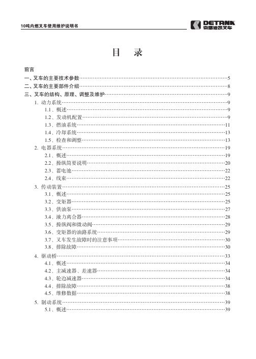
10t内叉使用说明书版面
83/2000
416.8/1500
353/1650
450/1450
232动/动力制动
动力制动
390
390
325
390
340
450
450
380
415
370
km/h
26/28
%
20
kn
53
53
52
26/30
51
57
g6g
2
10吨内燃叉车使用维护说明书
RASA:直角堆垛通道宽度 a:间隙 b:载荷长度
图 1.1
1.2、发动机配置
5-7t 叉车,国产发动机配置以朝柴 6102BG31 为主,8-10t 叉车,国产发动机配置以锡柴 CA6110 为主。5-10 吨叉车进口发动机,以五十䪗 6BG1QC-02 发动机为主,其结构见图 1.2, 以上发动机主要性能参数及配置见表 1.1。
图 1.2 6BG1QC-02 柴油机 5
泵形式
齿轮式
齿轮式
驱动形式
凸轮轴驱动
凸轮轴驱动
润滑 装置
油压调整装置 油压指示装置
活塞、弹簧式 开关式(0.3kg/cm2)
5-7吨叉车产品基本资料(doc 7页)

5-7吨叉车产品基本资料(doc 7页)部门: xxx时间: xxx整理范文,仅供参考,可下载自行编辑5-7吨叉车产品介绍大连叉车有限责任公司生产的5T系列叉车,根据配置的不同有多种型号产品可供选择,CPCD50-CPCD70型叉车是大连叉车有限责任公司内燃叉车产品系列品种之一。
是在总结国内外不同的生产厂家同类产品使用情况、产品可靠性、维修保养方便性以及使用成本等产品使用性能的基础上,经几代严密的更新设计、强化实验、工业性作业测试及港口试用而开发出来的系列高可靠性专用型产品。
CPCD50-CPCD70型叉车是前轴驱动的内燃平衡重式液力传动叉车,为港口(高强度)型、替代进口型产品,它是在总结国内用户使用三十年来前几代产品使用状况基础上,进一步汲取广大用户意见,尤其根据各大港口用户提出的要求,为缩小技术、结构以及部套配置上与国外同类产品的差距,开发的车型。
可称为适用于中国国情的,集专业技术、引进技术和创新技术相结合于一体,在不同工况作业条件下已得到充分验证,是目前国产叉车中较为成熟和完美的产品。
该系列叉车目前在中国港口叉车占有率最高。
中国同行业同吨级产品中唯一被国家评定为“部优产品”、“中国机械工业名牌产品” 和“全国机械工业用户满意产品”。
CPCD50-CPCD70型叉车以其同类产品中无可比拟的结构配置优势和真正意义上的可靠性,已被诸多用户认定为替代和更新其他同类产品的首选,自投放市场以来,以良好的运搬作业性能和使用可靠性得到了用户的广泛好评。
5-7吨内燃叉车产品特点★优质结构钢焊接而成的箱式机架。
具有很高的强度和刚性,防止重载或不良路面作业条件下可能产生的变形。
刚性和强度专门适应于不良作业环境。
★适用于多种作业方式的加强型宽视野升降机构。
门架利用的反变形专有技术系我公司多年叉车制造经验,不仅选用优质Q345A钢材门架翼板和腹板厚度与普通焊接而成的门架有所不同,而且焊接型式和焊接方法可保证克服了强外力及内应力可能引起的门架变形。
黑鹰自动汽车5吨和10吨汽车扳手和汽车扳手杆说明书

Model Capacity BH6050 (Manual) 5 Ton BH6051 (Air/Manual) 5 TonBH601010 Ton BH6011 10 TonLong Chassis Hydraulic Service JacksOperating Instructions & Parts ManualSFA Companies10939 N. Pomona Ave. Kansas City, MO 64153******************************SPeCiFiCatiOnSModel Capacity Jack Size ( L x W x H)Min. Height Max. Height Ram Extend Saddle Dia.BH6050/ BH6051 5 Ton 57 3/4" x 17" x 7 5/8"7"27"5" 6 1/2"SaFetY and GeneraL inFOrMatiOnSave these instructions. For your safety, read, understand, and follow the information provided with and on this jack before using. The owner and operator of this equipment shall have an understanding of this jack and safe operating procedures before attempting to use. The owner and operator shall be aware that use and repair of this product may require special skills and knowledge. Instructions and safety information shall be conveyed in the operator's native language before use of this jack is authorized. If any doubt exists as to the safe and proper use of this jack, remove from service immediately.inspect before each use. Do not use if broken, bent, cracked or damaged parts are noted. Any jack that appears damaged in any way, or operates abnormally shall be removed from service immediately. If the jack has been or suspected to have been subjected to a shock load (a load dropped suddenly, unexpectedly upon it), immediately discontinue use until jack has been checked by a factory authorized service center (contact distributor or manufacturer for list of authorized service centers). It is recommended that an annual inspection be done by qualified personnel. Labels and Operator's Manuals are available from manufacturer.PrOdUCt deSCriPtiOnBlackhawk Automotive Long Chassis Hydraulic Service Jacks are designed to lift, but not support, one end of a vehicle. Immediately after lifting, loads must be supported by a pair of appropriately rated jack stands. Air actuated function available for Models BH6051 & BH6011. *************************************************minimum of 150 PSI air pressure is required to raise rated capacity load.NEVER use hydraulic jack as stand-alone device. After lifting, immediately support the lifted vehicle with One Year LiMited WarrantYFor a period of one (1) year from date of purchase, SFA Companies will repair or replace, at its option, without charge, any of its products which fails due to a defect in material or workmanship under normal usage. This limited warranty is a consumer’s exclusive remedy.Performance of any obligation under this warranty may be obtained by returning the warranted product, freight prepaid, to SFA Companies Warranty Service Department, 10939 N. Pomona Ave., Kansas city, MO 64153.Except where such limitations and exclusions are specifically prohibited by applicable law.(1) THE CONSUMER’S SOLE AND EXCLUSIVE REMEDY SHALL BE THE REPAIR OR REPLACEMENT OF DEFECTIVE PRODUCTS AS DESCRIBED ABOVE.(2) SFA COMPANIES SHALL NOT BE LIABLE FOR ANY CONSEQUENTIAL OR INCIDENTAL DAMAGE OR LOSS WHATSOEVER.(3) ANY IMPLIED WARRANTIES, INCLUDING WITHOUT LIMITATION THE IMPLIED WARRANTIES OF MERCHANTABILITY AND FITNESS FOR A PARTICULAR PURPOSE, SHALL BE LIMITED TO ONE YEAR, OTHERWISE THE REPAIR, REPLACEMENT OR REFUND AS PROVIDED UNDER THIS EXPRESS LIMITED WARRANTY IS THE EXCLUSIVE REMEDY OF THE CONSUMER, AND IS PROVIDED IN LIEU OF ALL OTHER WARRANTIES, EXPRESS OR IMPLIED.(4) ANY MODIFICATION, ALTERATION, ABUSE, UNAUTHORIZED SERVICE OR ORNAMENTAL DESIGN VOIDS THIS WARRANTY AND IS NOT COVERED BY THIS WARRANTY .Some states do not allow limitations on how long an implied warranty lasts, so the above limitation may not apply to you. Some states do not allow the exclusion or limitation of incidental or consequential damages, so the above limitation or exclusion may not apply to you. This warranty gives you specific legal rights, and you may also have other rights which vary from state to state.PreParatiOnassemblyAlways secure the handle into the handle sleeve by means of the bolt lock washer and nut provided. Tighten securely to prevent accidental removal of handle while in use.Before Use1. Verify that the product and application are compatible, if in doubt call Technical Service (816) 891-6390.2. Before using this product, read the operator's manual completely and familiarize yourself thoroughly with theproduct, its components and recognize the hazards associated with its use.3. To familiarize yourself with basic operation, turn the release valve (handle knob):a. Clockwise until firm resistance is felt to further turning. This is the ‘CLOSed’ release valve position used toraise the saddle.b. Counter-clockwise, but no more than 1 turn from the closed position. This is the ‘OPen’ release valveposition used to lower the saddle.4. With saddle fully lowered, locate and remove cover plate, then remove the oil filler plug/screw. Pump 6 to 8 fullstrokes. This will help release any pressurized air which may be trapped within the reservoir. Check oil level. Proper oil level will vary from just covering the ram cylinder to 3/16” above it as seen from the oil filler hole. Reinstall the oil filler plug/screw.5. For air option models BH6051 & BH6011, Pour a teaspoon of good quality, air tool lubricant into the air supply inletof the lift control valve. Connect to air supply and operate for 3 seconds to evenly distribute lubricant.note: These models are equipped with the popular 1/4" NPT air coupler. When installing a different air coupler of your choice, ensure that thread tape or compound is used when servicing connections. To ensure dependable, trouble free operation an inline air dryer and oiler is recommended.6. Ensure that jack rolls freely. Raise and lower the unloaded saddle throughout the lifting range before putting intoservice to ensure the pump operates smoothly. Replace worn or damaged parts and assemblies with Blackhawk authorized replacement parts only.Bleeding / venting trapped airWith the release valve in the OPEN position (3b.) and with saddle fully lowered, locate and remove the oil filler plug/ screw. Pump 6 to 8 full strokes. This will help release any pressurized air which may be trapped within the reservoir. Reinstall the oil filler plug/screw.OPeratiOnLifting Only attachments and/or adapters supplied by the manufacturer shall be used. Lift only on area of the vehicle as specified by the vehicle manufacturer.note: The jack is equipped with handle position lock. To adjust the handle, release lock device by pulling the lever up, then back until lever is locked into place.1. Follow the vehicle manufacturer’s recommended guidelines for lifting. Engage the emergency brake and chock each unlifted wheel in both directions to prevent inadvertent vehicle movement.2. Locate and close the release valve by turning the release valve knob clockwise until firm resistance is felt.3. Refer to the vehicle manufacturer owner’s manual to locate approved lifting points on the vehicle. Center jack saddle under lift point.4. Verify lift point, then pump handle or foot pedal to contact lift point. To lift, pump handle or squeeze lift control valve (models BH6051 & BH6011) until load reaches desired height. never use foot pedal to raise load.5. Transfer the load immediately to appropriately rated jack stands.NEVER use hydraulic jack as a stand alone device! ALWAYS transfer the lifted load IMMEDIATELY to a pair only! Do not exceed rated capacity.LoweringBe sure all tools and personnel are clear before lowering load. Slowly open the release valve! The more Maintain control of the rate of speed at which the load lowers at all times!1. Raise load high enough to clear the jack stands.2. Remove jack stands carefully (always used in pairs).3. Slowly turn the release valve knob counter-clockwise, but no more than 1 full turn. If the load fails to lower: a. Use another jack to raise the vehicle high enough to reinstall jack stands. b. Remove the malfunctioning jack and then the jack stands. c. Use the functioning jack to lower the vehicle .4.trOUBLeSHOOtinGSymptomPossible CausesCorrective actionJack will not lift load• Release valve not tightly closed • Overload condition• Air pressure inadequate • Ensure release valve tightly closed • Remedy overload condition • Ensure adequate air pressure Jack will lift, but not maintain pressure• Release valve not tightly closed • Overload condition• Hydraulic unit malfunction • Ensure release valve tightly closed • Remedy overload condition • Discontinue use, contact Blackhawk Technical Service Jack will not lower after unloading• Reservoir overfilled • Linkages binding • Drain fluid to proper level• Clean and lubricate moving parts Poor lift performance• Fluid level low• Air trapped in system• Ensure proper fluid level• With ram fully retracted, remove oil filler plug/screw to let pressurized air escape. Reinstall oil filler plug/screwWill not lift to full extension • Fluid level low• Ensure proper fluid levelMaintenanCeimportant: Use only good grade hydraulic jack oil. Avoid mixing different types of fluid and never use brake fluid, turbine oil, transmission fluid, motor oil or glycerin. Improper fluid can cause failure of the jack and the potential for sudden and immediate loss of load. We recommend Hein-Werner HW93291 or equivalent.adding oil1. With saddle fully lowered set jack in its upright, level position. Locate and remove oil filler plug/screw.2. Fill with oil until ~3/16" above the inner cylinder as seen from the oil filler hole. Reinstall the oil filler plug/screw. Changing oilFor best performance, replace the complete fluid supply at least once per year.1. With saddle fully lowered, remove the oil filler plug/screw.2. Lay the jack on its side and drain the fluid into a suitable container.note: Dispose of hydraulic fluid in accordance with local regulations.3. Fill with oil until ~3/16" above the inner cylinder as seen from the oil filler hole. Reinstall the oil filler plug/screw.LubricationA periodic coating of light lubricating oil to pivot points, axles and hinges will help to prevent rust and assure that wheels, casters and pump assemblies move freely. To help ensure trouble free operation, an inline air dryer and oiler is recommended.CleaningPeriodically check the pump piston and ram for signs of rust or corrosion. Clean as needed and wipe with an oily cloth.note: Never use sandpaper or abrasive material on these surfaces!StorageWhen not in use, store the jack with saddle fully lowered.rePLaCeMent PartS(refer to page 6 thru 8)Not all components of the jack are replacement items, but are illustrated as a convenient reference of location and position in the assembly sequence. When ordering parts, give Model number, serial number and parts description. Call or write for current pricing: SFA Companies, 10939 N. Pomona Ave. Kansas City, MO 64153, U.S.A. Tel:(816)891-6390 Fax:(816)891-6599 E-Mail:******************************328ABCDEAFGIIHHJ214567891011121314151617181921202223242526272930313233343537383940(f or BH6050)(f or B H6051)413642replacement Parts List:Item Part# for BH6050Part# for BH6051Part# for BH6011Part# for BH6010Description Qty 1G251-20008-000G251-20008-000Filter1 2G250-20002-000G100-40003-000Reservoir135905-00100-200N/A Filler Plug1 N/A G62S-03301-000Filler Screw145901-00071-000O-ring, D7.1x2.651 5G250-20004-000Release Valve1 6G250-24000-000G100-43000-000Hyd. Cartridge1 7B300-14002-000Washer1 8G651-31002-000Pump Cylinder1 9G651-31001-000Pump Piston1 10G250-23000-000G100-44000-000Hyd. Cartridge1 11G250-30000-000G100-90049-K01Universal Joint1 12G251-00005-000N/A Spring1 135405-12036-0005405-12039-000Pin2 145405-02028-000Retaining Pin2 15G250-50000-000G100-70000-000Piston Link1 16G251-00004-000 (1 pc. only)G100-00015-000Return Spring, Pedal2175110-06016-000N/A Screw1 N/A5402-05025-000Pin118G251-00009-000Foot Pedal1 19G251-00010-000Handle Sleeve1 205304-00018-000Snap Ring2 21G251-00003-000G100-00014-000Return Spring2 225304-00028-0005304-00024-000Snap Ring2 23G251-00002-000G100-90049-K02Saddle1 245110-06010-0005111-55022-000Screw, Philips4 25G250-00002-000G100-00016-000Cover1 26G251-40001-000Knob1 275402-04028-000Spring Pin128N/A A070-40009-000N/AHose clip1295110-04012-000Screw, Philips1 305105-05012-000N/A Screw1 31G250-70000-000G250-20000-000G100-40000-000G100-90049-K01Hyd. Power Unit132N/A A20060-0006N/AAir Hose133G240-01000-000Air Motor1 34A20060-0007Lift Control Valve1 35A20060-0015Hose Assembly1 36A20060-0016Quick coupler, Male37G250-40000-000G100-90009-K01Handle Assembly1 38G250-90004-K01G100-90004-K02Front Wheel Assembly1 39G250-90004-K02G661-90038-K03Caster Assembly1 40G250-90009-K03Bolt Assembly1 41G651-31000-000Pump Assembly1 42G251-00007-000Handle Grip2 *G2501S-074 ( includes 3,4 & A to J)G1001S-98 ( 4 & A to K)Seal Kit for Hyd. Unit1-N/A A27010-0000N/ASeal Kit for Air Motor1-A270-01100-0000Piston for Air Motor1 -BH6050-L0BH6051-L0BH6011-L0BH6010-L0Label (s)--BH6050-M1Manual-。
5-7吨叉车产品基本资料

5-7吨叉车产品介绍大连叉车有限责任公司生产的5T系列叉车,根据配置的不同有多种型号产品可供选择,CPCD50-CPCD70型叉车是大连叉车有限责任公司内燃叉车产品系列品种之一。
是在总结国内外不同的生产厂家同类产品使用情况、产品可靠性、维修保养方便性以及使用成本等产品使用性能的基础上,经几代严密的更新设计、强化实验、工业性作业测试及港口试用而开发出来的系列高可靠性专用型产品。
CPCD50-CPCD70型叉车是前轴驱动的内燃平衡重式液力传动叉车,为港口(高强度)型、替代进口型产品,它是在总结国内用户使用三十年来前几代产品使用状况基础上,进一步汲取广大用户意见,尤其根据各大港口用户提出的要求,为缩小技术、结构以及部套配置上与国外同类产品的差距,开发的车型。
可称为适用于中国国情的,集专业技术、引进技术和创新技术相结合于一体,在不同工况作业条件下已得到充分验证,是目前国产叉车中较为成熟和完美的产品。
该系列叉车目前在中国港口叉车占有率最高。
中国同行业同吨级产品中唯一被国家评定为“部优产品”、“中国机械工业名牌产品” 和“全国机械工业用户满意产品”。
CPCD50-CPCD70型叉车以其同类产品中无可比拟的结构配置优势和真正意义上的可靠性,已被诸多用户认定为替代和更新其他同类产品的首选,自投放市场以来,以良好的运搬作业性能和使用可靠性得到了用户的广泛好评。
5-7吨内燃叉车产品特点★优质结构钢焊接而成的箱式机架。
具有很高的强度和刚性,防止重载或不良路面作业条件下可能产生的变形。
刚性和强度专门适应于不良作业环境。
★适用于多种作业方式的加强型宽视野升降机构。
门架利用的反变形专有技术系我公司多年叉车制造经验,不仅选用优质Q345A钢材门架翼板和腹板厚度与普通焊接而成的门架有所不同,而且焊接型式和焊接方法可保证克服了强外力及内应力可能引起的门架变形。
★配装重载驱动桥。
充分考虑了整机在各种恶劣工况作业条件下,驱动桥所能承受的重载传动。
5吨重载型手动搬运车价格图片参数-邦势启

高品质手动搬运车、电动叉车价格优惠尽在邦势启
POSUP 邦势启 5 吨重载型手动搬运车 ●重型设计可搬运重载货物。
●独特的液压泵确保省力轻松地提升重载货物。
●重载负荷而轻松搬运! ●载轮:d=Ø80×68 毫米, 双轮钢制 ●驱动轮:D=Ø200×50 毫米, 钢制 注:在选购电动叉车、电动搬运车、手动搬运车、电动观光车及了解叉车价格之前,一定要 登录邦势启官网或咨询免费电话 400-7283-599 咨询客服每个型号的不同用途及特点,这样 才能准确选择自己需要的产品,避免带来不必要的麻烦。
货号 额定载重 货叉最高高度 货叉最低高度 货叉长度 货叉外宽宽度 单货叉宽 前轮尺寸及材质 后轮尺寸及材质 净重
单位 kg mm mm mm mm mm mm mm kg
PD010009 5000 200 90 1150 580 210 Φ80×70 Φ200×50 192
PD010010 5000 200 90 1150 680 210
200
高品质手动搬运车、电动叉车价格优惠尽在邦势启
手动搬运车产品来源:邦势启工业设备(上海)有限公司官网: 扫一扫关注邦势启微信,有惊喜等你来哦
。
t叉车技术参数

起动方式
防爆电起动
冷却方式
水冷强制循环
制动形式
液压鼓式制动
使用环境温度(℃)
-10℃—+40℃
最大噪音 dB(A)
< 90
牵引高度(mm)
390
590±15
后悬距 mm
600±20
最大起升高度 mm
3000
自由起升高度 mm
205
门架前倾角 °
6
门架后倾角 °
12
空载起升速度 mm/s
500
满载起升速度 mm/s
400
最大运行速度 km/h
26±2
空载最大牵引力 kN
23
满载最大牵引力 kN
54
空载爬坡度 %
22
满载爬坡度 %
28
配套防爆柴油机
5T叉车主要性能与技术参数
性能项目
技术参数及规格
型号
CPCDB50
外形尺寸(长、宽、高) mm
(4660±40)×(1995±15)×(2500±25)
整备质量 kg
7980±100
最小离地间隙(驱动桥处) mm
190
轴距 mm
2250±20
前轮距 mm
1470±25
后轮距 mm
1700±30
前悬距 mm
1、生产用5吨叉车:

1、生产用5吨叉车:大连叉车CPCD50内燃平衡重叉车参数叉车型号:C PCD50设备代码: C D-AA额定起重量(Kg):5000最大起升高度(mm):3000载荷中心距(mm):600满载:530 空载:560最大起升速度(满载)(mm/s):门架倾角前/后(deg):6/12行驶速度(空载)(Km/h):26最小转弯半径(mm):3250爬坡度(%):(满载/空载)33/22全长(G)(mm):4765全宽(H)(mm):2000全高(J)(mm):2500护顶架高度(mm):2500轴距(L)(mm):2200轮距(mm):前轮: 1490后轮: 1520自重(Kg):8200发动机:型号: 朝柴CY6102BG额定功率: 81/2500 Kw/rpm最大扭矩: 353/1700 Nm/rpm油箱容量:100L轮胎:前轮: 8.25×20-14PR后轮: 8.25×15-14PR传动形式:液力传动2、保洁用清扫车:ZLJ5100TXSE3型洗扫车简介ZLJ5100TXSE3型洗扫车是中联重科股份有限公司引领市场需求、创新开发的一款集扫路车和高压清洗车功能于一体的高效环卫设备。
该车机动性能好,油耗低、噪声小、效率高,深受广大用户青睐。
特别适用于城市道路路面、路沿、路沿石立面和上表面的清洗,并且能回收清洗污水。
它拥有多项专利,综合技术性能处于国际领先地位。
该车采用高压力、低流量水流冲洗,并结合扫刷刷洗路面,吸嘴收集污水,实现了强力去污、高效节水、污物及污水回收的目的。
作业时,外伸至路沿的左(右)旋转洗刷配合低压水首先对路面、路侧及路沿石上表面和立面进行刷洗,同时,紧随其后的吸嘴中的内置长排喷杆和左、右两侧的旋转喷杆喷出的高压水,对路面、路侧及路沿石上表面和立面进行高压冲洗,两侧喷杆形成的“V”型工作夹角,使清洗后的污水自动流向吸嘴,然后,吸嘴将汇集至吸嘴口的污水、吸入垃圾箱。
特种设备5吨叉车设计计算书
e1=(G0*x0-Q*a1)/(G0+Q) h g1=( G0* y0+Q*H1) /( G0+Q) i =e1/ hg1≥0.04 计算结果如下
结论:本工况下,叉车纵向稳定性满足要求,能保持稳定
1.2.2.2 叉车满载运行时的纵向稳定性
G0(kg) Q((kg) x0(m) y0(m) a1(m) H1(m) e1(m) h g1(m) i
算。
据《叉车》推荐公式
G=Q{(1.4R+C)/L(X′—X)+X/(X′—X)}式中
G——叉车自重
Q——额定起重量,Q=5000kg
C——载荷中心距,C=500mm
L——轴距,L=1800mm
R——前轮自由半径
R=367.5mm
X——满载后桥轴荷系数 X=0.12
X′——空载后桥轴荷系数 X′=0.58
结论:本工况下,叉车横向稳定性满足要求,能保持稳定
1.2.2.4 叉车空载运行时的横向稳定性 工况:空载货叉起升至 300 ㎜,门架最大后倾,在水平路面以上最大速度行驶,急转弯 e4=(L—x0)cosr h g4= y0 i4=e4/ hg4≥(15+1.1V)%=31.5% 计算结果如下 x0(m) y0(m) L(m) V(Km/h) r(°) e4(m) hg4(m) i4
机械传动效率η=0.9
1.2.4.1 该车辆行驶速度最大为 12KM/H,所以只考虑道路阻力即可,所需电机净功率
1.2.4.1.1 空载平路行驶
A,在良好的沥青,水泥路面上行驶
取滚动阻力系数 f=0.02,则道路阻力为
F1=G*f*9.8 =1489.6N
B,在碎石或硬土路面上行驶 取 f=0.03
1-10吨内燃叉车参数
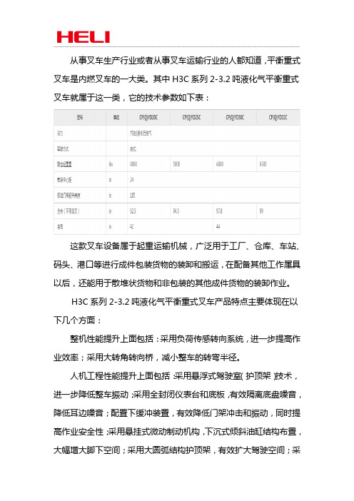
从事叉车生产行业或者从事叉车运输行业的人都知道,平衡重式叉车是内燃叉车的一大类。
其中H3C系列2-3.2吨液化气平衡重式叉车就属于这一类,它的技术参数如下表:这款叉车设备属于起重运输机械,广泛用于工厂、仓库、车站、码头、港口等进行成件包装货物的装卸和搬运,在配备其他工作属具以后,还能用于散堆状货物和非包装的其他成件货物的装卸作业。
H3C系列2-3.2吨液化气平衡重式叉车产品特点主要体现在以下几个方面:整机性能提升上面包括:采用负荷传感转向系统,进一步提高作业效率;采用大转角转向桥,减小整车的转弯半径。
人机工程性能提升上面包括:采用悬浮式驾驶室(护顶架)技术,进一步降低整车振动;采用全封闭仪表台和底板,有效隔离底盘噪音,降低耳边噪音;配置下缓冲装置,有效降低门架冲击和振动,同时提高作业安全性;采用悬挂式微动制动机构,下沉式倾斜油缸结构布置,大幅增大脚下空间;采用大圆弧结构护顶架,有效扩大驾驶空间;采用小直径方向盘和电液换向结构,同时轿车化双向手柄布置,大幅度提升驾驶舒适性;采用人体工学设计的半包腰座椅,提高座椅舒适性、更好的保护驾驶员腰部。
安全可靠性提升上面包括:热风回流隔离装置,优化的散热风道,铝制板翅式水箱,全面提升散热能力,确保发动机可靠工作;关键结构件如车架、门架、护顶架、转向桥等优化设计,全面提升整车安全和可靠性。
维修便捷性提升上面包括:减小固定式前底板尺寸,增大变速箱维护空间;增大了机罩开启角度,为检查和维护提供更加宽敞的作业空间。
节能环保上面包括:采用优化设计的液压系统,凸显节能高效,有效降低整车的燃油消耗;配置压力燃油加油盖,有效防止燃油挥发,降低燃油消耗和提高环保安全性;发动机排放满足美国CARB4法规要求。
安徽合力股份有限公司系安徽叉车集团有限责任公司核心控股子公司。
合力叉车主导产品是“合力、HELI”牌系列叉车,在线生产的1700多种型号、512类产品全部具有自主知识产权。
不远的将来,合力叉车将秉持“世界五强百年合力”的企业愿景,以“变革、创新、开放、合作”为动力,以“合理运营管理系统(HOS)”为支撑,加快“产品、市场、产业”三大结构调整,构筑“国内叉车、国际叉车、后市场、零部件、自动化物流设备”五大业务版块,致力于成为全球叉车专家及中国自动化物流设备供应商。
预制混凝土盾构管片生产施工方案新样本
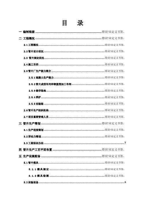
目录一编制根据 ............................................................................................ 错误!未定义书签。
二工程概况 ............................................................................................ 错误!未定义书签。
2.1工程概况........................................................................................................ 错误!未定义书签。
2.2管片设计状况 ................................................................................................ 错误!未定义书签。
2.3 管片规定状况 ............................................................................................... 错误!未定义书签。
2.4施工目的........................................................................................................ 错误!未定义书签。
2.5管片厂生产能力简介 .................................................................................... 错误!未定义书签。
2.5.1混凝土生产能力 ................................................................................ 错误!未定义书签。
黑鹰自动车辆10吨搬运机操作说明书

Operating Instructions & Parts ManualSFA Companies ©200410939 N. Pomona Ave. Kansas City, MO 64153816-891-6390******************************-Before using this product, read this manual and follow all its Safety Rules and Operating InstructionsLong ChassisHydraulic Service JacksModel Number BH6010BH6011 (Air/Lever Actuated Model)Capacity 10 Ton 10 TonTABLE OF CONTENTSWarranty P2Save These Instructions P3 Product Description P3 Specifications & Safety Instructions P3 Assembly P4 Operation P5 Maintenance P5 Troubleshooting P6 Replacement Parts P6ONE YEAR LIMITED WARRANTYFor a period of one (1) year from date of purchase, SFA Companies will repair or replace, at its option, without charge, any of its products which fails due to a defect in material or workmanship, or which fails to conform to any implied warranty not excluded hereby.Performance of any obligation under this warranty may be obtained by returning the warranted product, freight prepaid, to SFA Companies Warranty Service Department, 10939 N. Pomona Ave., Kansas City, MO 64153.Except where such limitations and exclusions are specifically prohibited by applicable law.(1) THE CONSUMER'S SOLE AND EXCLUSIVE REMEDY SHALL BE THE REPAIR OR REPLACEMENT OF DEFECTIVE PRODUCTS AS DESCRIBED ABOVE(2)SFA COMPANIES SHALL NOT BE LIABLE FOR ANY CONSEQUENTIAL OR INCIDENTAL DAMAGE OR LOSS WHAT-SOEVER.(3) THE DURATION OF ANY AND ALL EXPRESSED AND IMPLIED WARRANTIES, INCLUDING WITHOUT LIMITATION, ANY WARRANTIES OF MERCHANTABILITY AND FITNESS FOR A PARTICULAR PURPOSE, IS LIMITED TO A PERIOD OF ONE (1) YEAR FROM DATE OF PURCHASE.Some states do not allow limitation on how long an implied warranty lasts, so the above limitations may not apply to you. Some states do not allow the exclusion or limitation of incidental or consequential damages, so the above limitation or exclusion may not apply to you. This warranty gives you specific legal rights, and you may also have other rights which vary from state to state.SAVE THESE INSTRUCTIONSFor your safety, read, understand, and follow the information provided with and on this jack. The owner and operator of this equipment shall have an understanding of this jack and safe operating procedures before attempting to use. The owner and operator shall be aware that use and repair of this product may require special skills and knowledge. Instructions and safety information shall be conveyed in the operator's native language before use of this jack is authorized. If any doubt exists as to the safe and proper use of this jack, remove from service immediately.Inspect before each use. Do not use if there are broken, bent, cracked, or damaged parts (including labels). Any jack that appears damaged in any way, operates abnormally or is missing parts, shall be removed from service immediately. If the jack has been or suspected to have been subjected to a shock load (a load dropped suddenly, unexpectedly upon it), immediately discontinue to use until jack has been inspected by a Blackhawk authorized service center. It is recommended that an annual inspection be done by qualified personnel. Labels and Operator's Manual are available from manufacturer. PRODUCT DESCRIPTIONBlackhawk Long Chassis Hydraulic Service Jacks are designed to lift, but not sustaining, up to rated capacity loads. They are designed to be used in conjunction with jack stands. Intended use: To lift one wheel or one axle of a vehicle for the purpose of service and/or repair of vehicle components. After lifting, loads must be immediately supported by appropriately rated jack stands. Check with vehicle owner's manual for proper lift points.The air actuated unit requires at least 7.8 CFM @ 90 - 175 PSI.DO NOT USE TO DOLLY OR MOVE VEHICLE.DO NOT USE FOR ANY PURPOSE OTHER THAN THOSE USES OUTLINED ABOVE !SPECIFICATIONSSAFETY INSTRUCTIONSBEFORE USE1. Verify that the product and the application are compatible, if in doubt call Blackhawk Automotive Technical Service(816)891-6390.2. Read the operator's manual completely and familiarize yourself thoroughly with the product, its components andrecognize the potential hazards associated with its use before using this product.3. Secure the handle into the handle sleeve by means of the bolt and lock washer provided. Tighten securely to preventaccidental removal of handle while in use.4.Locate and turn the handle knob counterclockwise to open the release valve (no more than 2 full turns).5. With saddle fully lowered, locate and remove the oil filler plug. This will help release any pressurized air which may betrapped within the reservoir. Ensure the oil level is just below the oil filler plug hole.6. Pump 6 to 8 full strokes. Ensure the oil level is within ~ 3/16" from the inner cylinder as viewed from the oil filler hole.7. Ensure the jack rolls freely, that the pump and release valve operates smoothly, raises and lowers the unloadedsaddle throughout the lift range before putting into service.8. Replace worn or damaged parts and assemblies with Blackhawk Replacement Parts only. (See Replacement PartsSection). Lubricate as instructed in Maintenance Section.9. Model BH6011 is fitted to accept the popular 1/4" PT air nipple. When installing 1/4" PT nipple of your choice, ensurethat thread tape or compound is used when servicing connections. To help ensure trouble free operation, an inline air dryer and oiler is recommended.•Study, understand, and follow all instructionsprovided with and on this device before operating this device.•Do not exceed rated capacity.•This is a lifting device only.•After lifting, immediately transfer the load to appro-priately rated vehicle stands.•Never work on, under, or around a load supported by this device.•Use only on hard, level surfaces capable of sustain-ing rated capacity loads.•Do not move or dolly loads with this device.•Do not modify this device.•Do not use adapters or accessories that are not provided initially.•Lift only on areas of the vehicle as specified by the vehicle manufacturer.•Failure to heed these markings may result in personal injury and/or property damage.• Leer, comprender, y seguir las instrucciónes antes de utilizar el aparato.• El manual de instrucciónes y la información de seguridad deben estar comunicado en lengua del operador antes del uso.• No seguir estas indicaciónes puede causar daños personales o materiales.! WARNING! ADVERTENCIAFigure 1 - Model BH6010 ComponentsFigure 2 - Model BH6011 Componentshandle position lockASSEMBLYLittle, if any, assembly is required of these jacks. Always secure the handle into the handle sleeve by means of the bolt and lock washer provided. Tighten securely to prevent accidental removal of handle while in use. Familiarize yourself with the illustrations in the operator's manual. Know your jack and how it operates before attempting to use.OPERATIONLifting1. Place vehicle in park, with emergency brake on and wheels securely chocked to prevent inadvertent vehicle move-ment.2. Locate and close release valve by turning handle knob clockwise firmly. Center jack saddle under lift point.3. Verify lift point, then use handle pump or foot pedal to contact lift point. To lift, pump handle or squeeze lift controlvalve until load reaches desired height.Note: Never use foot pedal to raise load.4. Transfer the load immediately to appropriately rated jack stands.Note: All models are equipped with a handle position lock. To release lock device pull lever up, then back until lever is locked into place. This will allow full range of handle movement.Lowering1. Raise load high enough to clear the jack stands, then carefully remove jack stands (always used in pairs).2. Slowly turn the handle knob counterclockwise, but no more than 1/2 turn. If the load fails to lower:a. Use another jack to raise the vehicle high enough to reinstall jack stands.b. Remove the affected jack and then the stands.c. Using the other jack, lower the load by turning the operating handle counterclockwise, but no more than 1/2 turn.3. After removing jack from under the load, push saddle down to reduce ram exposure to rust and contamination. MAINTENANCEImportant: Use only a good grade hydraulic jack oil. Avoid mixing different types of fluid and Never use brake fluid, turbine oil, transmission fluid, motor oil or glycerin. Improper fluid can cause failure of the jack and the potential for sudden and immediate loss of load. We recommend Hein-Werner hydraulic jack oil HW 93291 or equivalent.Adding oil1. With saddle fully lowered, set jack in its upright, level position. Locate and remove oil filler plug.2. Fill with oil until ~3/16" above the inner cylinder as seen from the oil filler plug hole. Reinstall the oil filler plug. Changing oilFor best performance, replace the complete fluid supply at least once per year.1. With saddle fully lowered, remove the oil filler plug.2. Lay the jack on its side and drain the fluid into a suitable container.Note: Dispose of hydraulic fluid in accordance with local regulations.3. Fill with oil until ~3/16" above the inner cylinder as seen from the oil filler plug hole. Reinstall the oil filler plug. LubricationA periodic coating of light lubricating oil to pivot points, axles and hinges will help to prevent rust and assurethat wheels, casters and pump assemblies move freely. T o help ensure trouble free operation, an inline air dryer and oiler is recommended.CleaningPeriodically check the pump piston and ram for signs of rust or corrosion. Clean as needed and wipe with an oily cloth. Note: Never use sandpaper or abrasive material on these surfaces !StorageWhen not in use, store the jack with saddle fully lowered.TROUBLESHOOTINGREPLACEMENT PARTSAvailable Parts: Please refer to the Parts drawing when ordering parts. Not all components of the jack are replacement items, but are illustrated as a convenient reference of location and position in the assembly sequence. When ordering parts, give Model number, serial number and description on page 7. Call or write for current pricing: SFA Companies 10939 N. Pomona Ave. Kansas City, MO 64153, U.S.A. Tel:(816)891-6390 Fax:(816)891-6599E-Mail:******************************Models BH 6010 and BH6011*AVAILABLE FOR MODEL BH6011 ONLYFigure 3 - Replacement Parts Illustration for Model BH6010 and BH6011memo.。
5t叉车的标准荷载

5T叉车的标准荷载标准荷载是指叉车在正常工作条件下能够安全和有效携带的最大负载。
5吨叉车是一种承载能力为5吨的叉车,其标准荷载是根据制造商的规格和设计来确定的。
以下是关于5吨叉车标准荷载的一般性信息:5吨叉车的标准荷载:定义:5吨叉车的标准荷载是指在标准工作条件下,叉车能够安全和稳定地携带的最大负载重量。
制造商规格:标准荷载通常由叉车制造商在产品规格书和操作手册中明确说明。
这些规格包括有关叉车结构、引擎能力、车架强度等方面的信息。
工作条件:标准荷载通常是在理想的工作条件下确定的,包括平坦的地面、适当的气温、合适的气候条件等。
在实际工作中,荷载能力可能会受到其他因素的影响。
荷载中心:标准荷载通常与荷载中心有关。
荷载中心是指荷载在叉车叉臂上的分布位置。
通常,标准荷载是在标准的荷载中心下方(例如500毫米)确定的。
荷载分布:叉车标准荷载的计算还考虑荷载在叉臂上的均匀分布。
荷载不均匀分布可能会影响叉车的稳定性。
其他因素:制造商还可能考虑一些其他因素,如叉车的升降高度、叉臂的角度等,这些因素也可能对标准荷载产生影响。
注意事项:操作员应该严格遵循叉车制造商提供的操作手册中的荷载限制和操作规范。
在实际工作中,操作员应根据具体情况评估和确保叉车的荷载安全性。
如果有特殊工况或需要提高叉车的荷载能力,应该咨询制造商或专业工程师的建议。
最终,确保遵循叉车制造商提供的具体规格和建议,以保障叉车在操作中的安全性和效能。
如果您有特定的5吨叉车型号或制造商,建议查阅相关文档或与制造商联系以获取确切的标准荷载信息。
叉车检验报告样本
叉车检验报告样本1. 引言本报告旨在对叉车进行全面的检验,以确保其安全性和正常运行。
叉车是一种用于搬运和堆垛物品的重型设备,因此其操作安全性至关重要。
2. 检验对象本次检验的叉车为型号为ABC-123的电动叉车,用途为在仓储场地内搬运和堆垛货物。
下面将分别对叉车的外观、机械部件、电气系统和安全设备进行检查。
3. 外观检查3.1 车身外观叉车的车身外观需要进行全面的检查,包括但不限于以下几个方面:•车身是否存在明显的凹陷或划痕;•车漆是否完好,是否起泡或掉漆;•车窗、镜子和挡风玻璃是否完好;•灯光和指示器是否正常工作。
3.2 轮胎检查叉车的轮胎状况对于其正常运行至关重要,需要检查的内容包括:•轮胎胎面是否磨损严重;•轮胎气压是否符合规定;•是否存在轮胎漏气或漏胶的情况。
3.3 其他外观部件检查除了车身和轮胎外,还需要对其他外观部件进行检查,以确保其正常工作和完好无损,包括但不限于:•手把和踏板是否松动或损坏;•钢丝绳、电缆和管路是否损坏;•日光灯和工作灯是否正常工作。
4. 机械部件检查4.1 发动机检查叉车的发动机是其正常运行的核心部件,在检查时应特别注意以下几个方面:•发动机冷却液是否充足,并检查是否存在泄漏;•发动机皮带是否松动或磨损;•发动机燃料系统是否正常工作。
4.2 制动系统检查制动系统是叉车安全性的关键部分,应仔细检查以下几个方面:•制动液是否充足,是否需要更换;•制动踏板的行程是否正常;•制动是否灵敏且能够有效停车。
4.3 悬挂系统检查叉车的悬挂系统对于其稳定性和舒适性至关重要,需要注意以下几个方面:•悬挂系统是否存在异常噪音;•悬挂系统是否松动或磨损;•是否存在悬挂系统漏油的情况。
5. 电气系统检查5.1 电池检查电池是电动叉车的能源来源,应仔细检查以下几个方面:•电池是否充足,并检查电池的电量指示器;•电池是否存在漏液现象;•电池接线是否正常。
5.2 电控系统检查电控系统是叉车正常运行的关键部分,需要注意以下几个方面:•电控系统是否存在异常警报或故障代码;•操作控制器和显示器是否正常工作;•各个传感器是否正常响应。
10t行车技术文本

双梁桥式起重机(第二批)技术文本二○○八年一月总体要求及功能描述1 、起重机名称及数量:QD10 t吊钩桥式起重机 ,8台1 t悬挂式电动葫芦,4台2、起重机用途:主要用于仓库钢材装卸作业。
3、起重机主要技术性能表3.1起重机设计、制造、安装及调试要符合以下标准要求:起重机设计规范GB3811-83、通用桥式起重机技术GB/T14005-93、冶金起重机技术条件JB/T7688-95、起重机械安全规程GB6067-85、起重机电控设备JB4315-86。
桥式和门式起重机制造及轨道安装公差GB10183—88。
起重吊钩GB10051。
起重机试验规范和程序GB5905-863.2本招标书中的桥式起重机分布于仓储中心一号仓库和二号仓库共计8台,电动葫芦4台。
各起重机主要参数汇总见表1,桥式起重机的详细技术条件见起重机械设备订货技术条件表2~表5。
3.3起重机初定交货时间:2008年月,具体交货时间由招标方提前四个月通知投标方。
表1 仓储中心一号仓库的起重运输设备表仓储中心二号仓库的起重运输设备表4、结构4.1 主梁结构采用正轨箱型梁结构(要求主梁不能分段)。
4.2大小车金属结构件均采用热轧钢板制作,严禁用卷板替代。
4.3起重机的大车主梁腹板厚度宜≥8mm;端梁两头的内外腹板(大车轮处)再复贴一块钢板加固(加固板高度、厚度与母板相同,长度≈1.3倍高度);端梁上盖板两头也复贴一块钢板加固(上盖板加固板长度≥腹板加固板长度+200mm)。
所有加固板中部开若干个(孔距≈100mm)¢25mm孔,与母板塞焊,周边连续焊。
4.4为运输方便需要解体时,其分解面应选在应力小的部位。
采用足够强的搭接板,由高强度螺栓进行连接。
4.5焊缝与拐角:①焊缝:焊缝直观检查按GB6417技术要求,焊缝表面不得有可见的明显缺陷。
②拐角:所有结构件的拐角及工艺、安装孔须有园弧过度,Rmin≥20mm,且须砂轮机打磨倒顺。
4.6大小车轮处均增加方便更换车轮的顶升支点装置,以提高该部位的刚性,确保行走机构几何尺寸不变形。
叉车载重量标准

叉车是一种常见的物料搬运设备,也是物流系统中不可或缺的重要设备,其载重量标
准也是相当重要的。
叉车的载重量标准一般按照叉车的类型来定,比如一般定义标准叉车一般是1.5吨,2.5吨,3吨,4.5吨,5吨,6吨等,特种叉车的载重量标准则更高,比如有8吨,10
吨,15吨,20吨等。
另外,叉车的载重量标准还可以从叉车的结构来确定,比如液压叉车一般有2.5吨,3.5吨,4.5吨,5.5吨,6.5吨,7.5吨等,而电动叉车则有1吨,1.2吨,1.5吨,2吨,2.5吨,3吨等不同标准。
在购买叉车时,需要根据自己的生产实际需求,选择合适的载重量标准,以确保叉车
的使用及搬运效果。
同时,还需要注意叉车的使用环境,以选择合适的叉车型号,避免超载造成的安全事故。
