CLIMAX高压黄油枪10516
AUTOMATED EQUIPMENT LLC 产品说明书 P N 291035 英文版
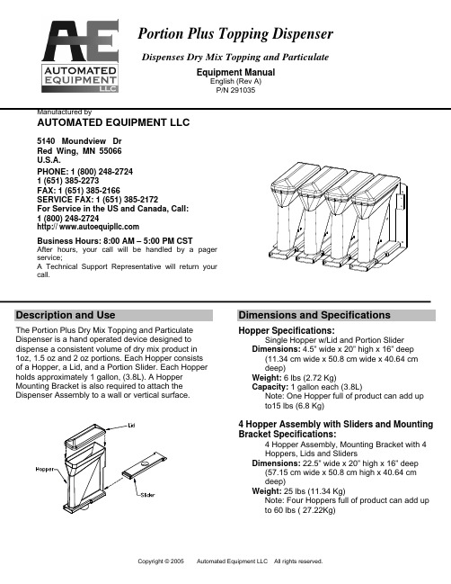
Portion Plus Topping DispenserDispenses Dry Mix Topping and ParticulateEquipment ManualEnglish (Rev A) P/N 291035Manufactured byAUTOMATED EQUIPMENT LLC5140 Moundview Dr Red Wing, MN 55066 U.S.A.PHONE: 1 (800) 248-2724 1 (651) 385-2273FAX: 1 (651) 385-2166SERVICE FAX: 1 (651) 385-2172For Service in the US and Canada, Call: 1 (800) 248-2724http:// Business Hours: 8:00 AM – 5:00 PM CSTAfter hours, your call will be handled by a pager service;A Technical Support Representative will return your call.Description and UseThe Portion Plus Dry Mix Topping and Particulate Dispenser is a hand operated device designed to dispense a consistent volume of dry mix product in 1oz, 1.5 oz and 2 oz portions. Each Hopper consists of a Hopper, a Lid, and a Portion Slider. Each Hopper holds approximately 1 gallon, (3.8L). A Hopper Mounting Bracket is also required to attach the Dispenser Assembly to a wall or vertical surface.Dimensions and SpecificationsHopper Specifications:Single Hopper w/Lid and Portion SliderDimensions: 4.5” wide x 20” high x 16” deep(11.34 cm wide x 50.8 cm wide x 40.64 cm deep)Weight: 6 lbs (2.72 Kg)Capacity: 1 gallon each (3.8L)Note: One Hopper full of product can add up to15 lbs (6.8 Kg)4 Hopper Assembly with Sliders and Mounting Bracket Specifications:4 Hopper Assembly, Mounting Bracket with 4 Hoppers, Lids and SlidersDimensions: 22.5” wide x 20” high x 16” deep(57.15 cm wide x 50.8 cm high x 40.64 cm deep)Weight: 25 lbs (11.34 Kg)Note: Four Hoppers full of product can add up to 60 lbs ( 27.22Kg)CleaningWarranty InformationThe Hopper, Lid, Slide, and Mounting Bracket are warranted to be free from manufacturing defects in material or workmanship for one (1) year. The warranty period commences on the shipping date and applies only to the original purchaser. Except as otherwise provided herein, Automated Equipment LLC, makes no other warranties, expressed or implied, and specifically disclaims any warranty of merchantability or fitness forparticular purpose. Automated Equipment LLC, shall not be liable for any direct, indirect, consequential damages (including damages for loss ofbusiness profits, business interruption, loss of business information and the like) arising out of the use of or inability to use this product. This warranty is void if the product is not functioning correctly due to abuse or neglect by the purchaser, its employees, agents, or other representatives either by breaking, bending, misuse, abuse, dropping, alteration, improper installation or maintenance, or any other form of neglect or improper usage. This warranty does not cover damage to the product caused by natural causes such as lightning, flood, fire, tornadoes, or other acts of God. This warranty is governed by the substantive laws of Minnesota, USA, without giving effect to the conflict of law provisions.• Use water, a soft brush and mild detergent tothoroughly clean all parts of the Dispenser.• Do not use abrasive cleaning pads or cleansers. • Frequent cleaning will prevent food buildup on thesliding parts and ensure proper operation.Warning!• Do not use a dishwasher to clean the Dispensercomponents. Hand wash only.• Do not use excessive force to operate the Sliders. • Dispense dry products only. Do not attempt todispense frozen or liquid products.• Do not attach or hang other material or equipmenton the Mounting Bracket or Hopper Assembly .The information in this manual is subject to change without notice. In no event will Automated Equipment LLC, be liable for technical or editorial omissions made herein; nor for direct, special, incidental, or consequential damages resulting from the furnishing, performance, or use of this material.。
林肯油脂泵P203-2XL-1K6-24-2A6

ITALVIBRAS 振动电机、AVITEQ 振动电机、FRIEDRICH 振动电机、德瑞克DERRICK 电机、德瑞克DERRICK 筛网、欧力卧龙振动电机、德国mogensen(摩根森)筛网、电机、SCHENCK(申克)德国激振器、美国CONN-WELD 康威德激振器、马丁电机、Kem-Tron (坎特龙)振动电机、MASTERVOCT 电机小兰:180 **** ****林肯清脂枪1100CLR林肯清脂枪1107CLR林肯清脂枪1134CLR林肯清脂枪1142CLR林肯清脂枪1148CLR林肯清脂枪1240CLR林肯清脂枪1440CLR林肯重型气动黄油枪1164林肯重型气动黄油枪1013林肯重型气动黄油枪1145林肯重型气动黄油枪1035林肯重型气动黄油枪1037林肯重型杠杆式黄油枪1142林肯重型杠杆式黄油枪1147林肯重型杠杆式黄油枪1148林肯重型杠杆式黄油枪1151林肯重型手枪握式黄油枪1132林肯重型手枪握式黄油枪1133林肯重型手枪握式黄油枪1134林肯黄油枪座82760林肯油管连接器91108林肯黄油枪1244林肯黄油枪1240林肯黄油枪1200林肯黄油枪1842林肯黄油枪1844林肯黄油枪1442林肯黄油枪1444林肯黄油枪1862林肯黄油枪1864林肯电池1861林肯充电器1850林肯箱子1236林肯油脂泵94012林肯油脂泵94412林肯油脂泵94812林肯油脂泵94812LDL林肯油脂泵94024林肯油脂泵94424林肯油脂泵94824林肯油脂泵94824LDL林肯油脂泵644-46278-1林肯油脂泵94222 P203-2XL-1K6-24-2A6林肯油脂泵94422 P203-4XLBO-1K6-24-2A6林肯油脂泵94822 P203-8XLBO-1K6-24-2A6林肯油脂泵94822LDL P203-8XL-1K6-24-2A6林肯油脂泵644-40987-2 P203-15XL-1K6-24-2A6林肯油脂泵644-40821-6 P203-2XLBO-1K6-12-2A6 林肯油脂泵644-40843-8 P203-4XLBO-1K6-12-2A6 林肯油脂泵644-40822-8 P203-8XLBO-1K6-12-2A6 林肯油脂泵644-40873-1 P203-8XLBO-1K6-AC-3A6林肯电动油脂泵94223-12林肯电动油脂泵94423-12林肯电动油脂泵94823-12林肯电动油脂泵94223林肯电动油脂泵94423林肯电动油脂泵94423LDL林肯电动油脂泵94823林肯电动油脂泵94823LDL林肯电动油脂泵94823林肯电动油脂泵94223-AC林肯电动油脂泵94423-AC林肯电动油脂泵94823-AC林肯电动油脂泵644-46073-5 P203-2XNBO-1K6-AC-1A1 林肯电动油脂泵644-46173-4 P203-4XNBO-1K6-AC-1A1 林肯电动油脂泵644-46173-5 P203-4YLBO-1K6-AC-1A1 林肯电动油脂泵644-46073-6 P203-2XNBO-1K6-AC-1A1 林肯电动油脂泵644-46173-6 P203-4XLBO-1K6-AC-2A1 林肯电动油脂泵644-46173-8 P203-4YLBO-1K6-AC-1A1 林肯电动油脂泵644-46173-7 P203-4XNBO-1K6-AC-1A1 林肯电动油脂泵644-46174-2 P203-8XLBO-1K6-AC-2A1 林肯电动油脂泵644-46174-4 P203-8XLBO-1K6-AC-2A1林肯电动油脂泵644-40824-1 P233-2XL-1K6-24-2A5林肯电动油脂泵644-40824-2 P233-2XLBO-1K6-24-2A5 林肯电动油脂泵644-40826-1 P233-4XLBO-1K6-24-2A5 林肯电动油脂泵94434LDL P233-4XL-1K6-24-2A5林肯电动油脂泵644-40827-1 P233-8XLBO-1K6-24-2A5 林肯电动油脂泵94834LDL P233-8XL-1k6-24-2A5林肯电动油脂泵644-41040-1 P233-15XL-1K6-24-2A5林肯电动油脂泵644-40868-1 P233-2XL-1K6-12-2A5林肯电动油脂泵644-40869-1 P233-4XLBO-1K6-12-2A5 林肯电动油脂泵644-40870-1 P233-8XLBO-1K6-12-2A5 林肯电动油脂泵644-40867-1 P233-8XLBO-1K6-AC-3A6林肯电动油脂泵P401 31202574林肯电动油脂泵P401 31402574林肯电动油脂泵P401 42601114林肯电动油脂泵P401 42801114林肯电动油脂泵P401 61202574林肯电动油脂泵P401 61402574林肯电动油脂泵P401 62601114林肯电动油脂泵P401 62801114林肯电动油脂泵P401 91202574林肯电动油脂泵P401 91402574林肯电动油脂泵P401 92601114林肯电动油脂泵P401 92801114林肯电动油脂泵P401 31401110林肯电动油脂泵P401 42600110林肯电动油脂泵P401 61401110林肯电动油脂泵P401 62600110林肯电动油脂泵P401 91401110林肯电动油脂泵P401 92600110林肯电动油脂泵P301 31211154林肯电动油脂泵P301 31411154 林肯电动油脂泵P301 42611114 林肯电动油脂泵P301 61211154 林肯电动油脂泵P301 61411154 林肯电动油脂泵P301 62611114 林肯电动油脂泵P301 62811114 林肯电动油脂泵P301 91211154 林肯电动油脂泵P301 91411154 林肯电动油脂泵P301 92611114 林肯电动油脂泵P301 92811114林肯电动油脂泵P311 31211154 林肯电动油脂泵P311 61211154 林肯电动油脂泵P311 91211154 林肯电动油脂泵P311 31411154 林肯电动油脂泵P311 61411154 林肯电动油脂泵P311 91411154 林肯电动油脂泵P311 42611114 林肯电动油脂泵P311 42811114 林肯电动油脂泵P311 62611114 林肯电动油脂泵P311 92611114 林肯电动油脂泵P311 62811114 林肯电动油脂泵P311 92811114 林肯电动油脂泵P301 31411110 林肯电动油脂泵P301 61411110林肯电动油脂泵P301 91411110林肯电动油脂泵P311 31411110林肯电动油脂泵P311 61411110林肯电动油脂泵650-40768-3林肯电动油脂泵650-40768-4林肯电动油脂泵650-40768-5林肯电动油脂泵650-40765-4林肯电动油脂泵650-40765-5林肯电动油脂泵650-40765-6林肯电动油脂泵P421 31402531林肯电动油脂泵P421 91402531林肯电动油脂泵P421 61202531林肯电动油脂泵P421 91202531林肯电动油脂泵P421 61222531林肯液压润滑泵271924林肯液压润滑泵271925林肯液压润滑泵271926林肯液压润滑泵271927林肯液压润滑泵271374 P203-4XNBO-1C7-24-1A1林肯液压润滑泵272633 P203-4XLBO-1C7-24-2A1林肯液压润滑泵272643 P203-4XLBO-1C7-12-2A1林肯液压润滑泵273426 P203-4XLBO-1K5-24-2A1林肯液压润滑泵272632 P203-8XLBO-1C7-24-2A1 林肯液压润滑泵273422 P203-8XLBO-2K7-24-2A1 林肯液压润滑泵273425 P203-8XLBO-1K7-24-2A1。
黄油枪
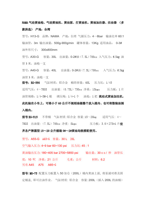
NAMA气动黄油枪、气动黄油机、黄油泵、打黄油机、黄油加注器、注油器(多款拱选)产地:台湾型号:H13-G 品牌:NAMA 产地:台湾气源压力:4—8bar 输油比率60:1 输油管:3m 输出油量:500g-900g/min 罐体容量:13Kg 适用油品:0-3#油外形尺寸:300x800mm型号:A30-G 容量:30L 出油量:0-2#油(7.5L)700cc 入气压力:6.5kg 油管3米,油枪一支型号:A40-G 容量:40L 出油量:0-2#油(7.5L)700cc 入气压力:6.5kg 油管3米,油枪一支型号:KG-590 气缸材质:铝合金桶的容量:60L 压力比:1/45适用气压:4~7KGS 出油量:(0.75L)750cc 净重:13kgs 压力板:1片油管规格:1/4-3M-1根调压阀:1/4-1个油抢:1把流动式黄油加注机,此机装在小车上,可将小于60公斤不规则油桶整个放入桶内、也可将散装油倒入桶内。
型号KG-515不带桶气缸材质:铝合金容量:15~20kg 适用气压: 4~7KGS 出油量:(7.5L)700cc 净重: 8kgs 压力板:3.0×278=1片世界各产牌圆型15~20公升桶装0#~2#黄油均能搭配使用。
型号:A55-G A65-G 容量:30 L 20L空气输入压力: 4~9 bar 60~130 psi压力比: 45 : 1黄油输出压力: 180~405 bar 2700~5850 psi输出量:30 c c / 秒油管长度:10 呎净重:21 公斤毛重:公斤材积:6.2另有A45 A75 A85-G型号: MG-75 配置压力板置入50加仑(200L)桶内黄油上面, 将泵浦对准及固定桶盖, 即可注油作业。
气缸材质: 铝合金容量: 200L(插入200L的油桶)泵浦可承压力: 4-9 kgs 压力比: 1:50 出油量: 2L/min(2公升/分钟)油管规格: 1/4"x2Wx6M净重: 13+12 kgs型号:KG-575 气缸材质:铝合金容量:200L 适合200公升大桶使用适用气压:4--10KGS压力比:1:50出油量:2# 1分钟/1050cc油管规格:1/4”*6M 净重:7+10KGS台湾久隆气动黄油枪,气动黄油加注机A55-G特点:1.桶身设计使用高级钢板,更坚固耐用。
加州空气工具5510SE油漆空气泵说明书

ULTRA QUIET & OIL FREEAIR COMPRESSOROwnER'S MAnUALCALIFORnIA AIR TOOLS5510SE1.0 HP3.10 CFM @ 40 PSI2.20 CFM @ 90 PSI5.5 gALLOn STEEL TAnk Customer Support 1-866-409-45812TAbLe OF CONTeNTSIntroductIon __________________________________2Important Safety InStructIonS _______________3LocatIonS of Important LabeLS _______________6aIr compreSSor componentS__________________7pre-operatIon checkLISt ______________________8package contents & assembly____________________8Inspect for damage _____________________________9Save packaging ________________________________9compressor Location ___________________________9electrical power _______________________________10operatIng the aIr compreSSor _______________10Introduction __________________________________10assembly ____________________________________10test run _____________________________________11daily operation ________________________________11maIntenance _________________________________12draining the air tank ___________________________12changing the air filter__________________________12testing for Leaks ______________________________12pressure Switch _______________________________12cleaning _____________________________________12Storage ______________________________________12troubLeShootIng ____________________________13SpecIfIcatIonS________________________________14electrical circuit _______________________________14air passage drawing ___________________________14Warranty ____________________________________15product regIStratIon________________________17thank you for purchasing a california air tools, Inc.air compressor.please contact us if you have any questions.record the model and serial numbers indicated on your air compressor’s nameplate:model no.________________________________________Serial no.________________________________________date of purchase:_________________________________Store/dealer:_____________________________________3Customer Support: 1-866-409-4581how to find a local service center:even quality built equipment might need service or repair parts.Contact the California Air T ools Customer Service department:Phone: 1-866-409-4581Online: please provide the information below:Model number and Serial number and specifications shown on the Model number/Serial number plate.Part number or numbers shown in the parts list section of the owner’s manual for your air compressor model.A brief description of the trouble with the air compressor.do not return your air compressor for service or parts to the store/dealer where purchased.IMPORTANT SAFeTy INSTRuCTIONSSafety messages & Signal Words:4Customer Support: 1-866-409-45815Customer Support: 1-866-409-45816Customer Support: 1-866-409-4581LOCATIONS OFIMPORTANT LAbeLSRead these important labels before operating.These labels provide important safety and maintenanceinformation. These labels should be considered as permanent parts of the air compressor. Should any of these labels become illegible, damaged or removed, please contact California Air T ools Customer Service department at 1-866-409-4581 for replacements.7 Customer Support: 1-866-409-45818PRe-OPeRATION CheCkLIST package contents & assembly model: 5510Sepackage contents:Air CompressorOwner's ManualAir FilterWheel Assembly kit2 - #60 Wheel bolts2 - #61 Washers2 - #62 Wheel2 - #58 Washer2 - #59 Nut1 - #69 bolt1 - #70 Washer1 - #71 Cushion Foot1 - #72 Nutassembly:Install the Air Filter1. Attach the air filter to the top rear of motor head.(looking from the front to the back of the air compressor ) Screw the air filter into the motor head port that is located under the Plastic head Cover I nstall the Wheel kit1. Slide Washer #61 through bolt #60.2. Slide bolt #60 through Wheel #62 .3. Slide the bolt #60 through the wheel support holelocated on the back bottom of the air compressor tank.4. Attached the Washer #58 and Nut #59 to the bolt #60 andtighten firmly.5. Repeat steps 1-3 to assemble the other wheel.6. Slide bolt #69 through Washer #70 and Cushion Foot #717. Slide bolt #69 through cushion foot support hole located onthe front bottom of the air compressor..Attach Nut #72 to bolt # 69 firmly.AIR COMPRESSORInspect for damagebefore using the air compressor, make sure the air tank is not damaged, inspect all parts for damage, and check that all pipes are firmly connected.do not use the air compressor if any damage is found. If damaged, have an authorized service center inspect and test the air compressor to ensure that is working properly.Save packagingIMPORTANT: Save all outside packaging in case you ever need to return the product for service or repair.compressor Locationuse on flat SurfaceFor proper operation, the air compressor must be placed on a flat surface with an incline no greater than 15 degrees.maintain a clear areaIt is very important that the air compressor is positioned so that there is adequate airflow around the machine. There must be at least 2 feet of obstacle-free space surrounding and above the air compressor.use in areas with clean airFor proper operation and to maximize the longevity of the air compressor, it is very important that the air drawn into the air compressor is clean. The air compressor should not be used in areas where dust or particulates are in the air. This will damage the motor and impair proper operation.Important:Always use the air filter, properly installed.9 Customer Support: 1-866-409-458110Customer Support: 1-866-409-4581AIR COMPRESSORelectrical powerelectrical power requirementsbefore using the air compressor, refer to the serial label for voltage and amperage requirements. Make sure you have a sufficient electrical supply for supporting the motor's requirements.use a dedicated circuit for the best results.Low voltage and/or an overload circuit can cause the motor's overload protection system circuit breaker to trip.electrical extension cordsInspect all electrical extension cords to ensure that they are free of damage.When using an extension cord, use a heavy-duty cord that is no more than 25 feet long and at least 14 e only a 3-wire extension cord that has a 3-blade grounding plug.OPeRATINg The AIR COMPReSSORSave this manual for future reference. IntroductionThis air compressor features a compact structure, stable performance, a high airflow rate, easy operation and maintenance. because the air compressor produces no oil in the airflow, it can be used as an independent air supply machine for situations in which oil in the airflow is an issue. The motor directly drives the pistons and is able to function without lubrication for a long period of time. assembly.1.Connect your air supply hose to a 1/4” male universal or industrial quick connect coupler. Connect the male quickconnect coupler to the female quick connect coupler located on the air compressor2.Make sure the drainage valve is off and that the pressure switchis in the OFF position.3.ensure that the power supply you are going to use is operatingnormally.4.Insert the power supply cord into the power supply socket.11Customer Support: 1-866-409-4581AIR COMPRESSORtest runbefore using the air compressor for the first time, complete a test run as follows:1.Turn the power switch to the OFF position. Plug the power supply cord into a power supply socket. Start the aircompressor by turning the power switch to the ON position.The pressure gauge reading will slowly rise as pressureincreases inside the air tank. When the gauge reading reaches 115 PSI - 120 PSI, the pressure switch will automatically turn the power off. This indicates the compressor is working normally. 2.Starting the compressor:1.Turn the power switch to the OFF position.2.Attach the air hose to the 1/4” quick connect coupler3.Close the drain valve.4. have air filter attached5.Plug the power supply cord into a power supply socket.6.Turn the power switch to the ON position.7.Let the motor run and tank fill until motor turns off.8. T o regulate the air flow.While the air compressor is running, turn “On” your tool and turn the regulator knob to the right increasing the pressure. Turn the pressure up until the desired pressure is reached.9. Operate air tool normally.Shutting down the compressor:1.Turn the power switch to the OFF position.2.unplug the power supply cord.3.Reduce the pressure in the air tank through the air supply hose.note: If the Air Compressor is not working properly, the pressure gauge will indicate that there is a decrease in pressure in the air tank. If there is an air leak from the compressor the pressure in the air tank decreases, the pressure switch resets and the motor automatically turns back on.If you detect an air leakage, turn the power switch to the Off position, release the air from the tank by pulling on the safety valve. unplug the power supply cord and contact Customer Support for Assistance.Turn the power switch to the Off position, unplug the power supply cord and release the air in the tank by pulling on the safety valve. At this point proceed to the next step (daily operations).AIR COMPRESSOR MAINTeNANCedraining the air tankThe frequency at which you should drain the air tank depends on the environmental conditions and the amount of operating time logged. The average draining frequency is every 2 to 3 days.1.Place the air compressor above a container capable of holdingwater.2.With compressed air in the air tank, slowly turn the drain valveknob to the forward (open) or straight position.The water in the air tank will drain out.3.After all of the accumulated water has drained out, turn thedrain valve knob to the closed or left position in order to avoid leakage.4. draining the air tank protects parts from rust and corrosion. cleaning or changing the air filterThe air filter is designed to reduce noise and help prevent particulates in the air from entering and damaging the air compressor.After being used for a period of time, the air filter will become clogged. This will reduce the air intake capabilities of the air compressor, reducing performance. Therefore, the air filter must be cleaned or replaced regularly.1.Open the lid on the air filter, then remove the air filter element.2.T o clean the element blow off or brush off the dirt and dust.3.If clogged, replace with a new air filter.testing for LeaksMake sure all connections are tight. do not overtighten.A small leak in any hose or pipe connection will reduce the air compressor's performance.T o test for small leaks, spray a small amount of soapy water on the area suspected of leaking. If the soap bubbles, replace the broken part.cleaningClean items with a soft brush, or wipe with a moistened cloth using a biodegradable solvent.do not use flammable liquids such as gasoline or alcohol. Always keep parts clean from dirt and dust for better performance.pressure SwitchThe pressure switch is factory pre-set to shut off at between 115 - 120 PSI and to re-start at between 85 -90 PSISTORAgebefore storing for a prolonged period of time:1.Turn off the power supply.2.disconnect the power cord from the power supply and wrapthe power cord around the air compressor handle to reduce the risk of damage.3.Pull the relief valve and release all the pressure from the airtank.4.Clean the air compressor to remove all dirt and dust.5.Cover the air compressor with a cover to protect the unit fromdust and moisture.6.do not stack or store any items on top of or around the aircompressor. damage could occur.12AIR COMPRESSOR TROubLeShOOTINg13Customer Support: 1-866-409-458114Customer Support: 1-866-409-4581SPeCIFICATIONSelectrical circuitair passage drawingAIR COMPRESSORMotorEarth wire (Green)Red cords for CapacitorElectric cord for motorSolenoid valveElectric cord for motor Pressure switchOverload protector (MAX temperature 135°C)Pressure switchSafety valvePressure gaugeRegulatorPressure gaugeBall valveFilterDrain valveAir intakeCheck valveSolenoid valveCompressorTankAIR COMPRESSOR CALIFORNIA AIR TOOLS INC. LIMITed WARRANTyThis warranty is limited to Air Compressors distributed by:California Air Tools, Inc.8560 Siempre Viva Road, unit 3San diego, CA 92154Limited WarrantyCalifornia Air T ools Inc. will repair or replace, free of charge, to the original retail customer who purchased a California Air T ools, Inc.Air Compressor from an authorized dealer, distributor or distributor’s dealer in North America.This warranty does not transfer to subsequent owners.California Air T ools Inc. will repair or replace, at its option, any parts of the portable air compressor that are proven by an authorized service center to be defective in material or workmanship under normal use during the applicable warranty time period as stated below. This limited warranty covers the cost of the replacement parts and labor for all defects when installed by an authorized service center. Transportation charges are the responsibility of the customer. Any part replaced under warranty becomes the property of California AirT ools Inc.All parts replaced under warranty will be considered as part of original product, and any warranty on those parts will expire coincident with the original product warranty.Limited Warranty periodsNon-commercial / Non-rental (personal use by a retail customer): 1 year parts and laborCommercial / Rental (usage for income, business use): 1 year parts and laborThe limited warranty period begins on the date of retail purchase by the original purchaser.disclaimers, Limitations of remedies & exclusionsThis warranty gives you specific legal rights, and you may also have other rights which may vary from state to state.disclaimer of other WarrantiesT o the fullest extent permitted by applicable law, this limited warranty is exclusive and expressly in lieu of any and all other warranties, including, without limitation, any implied warranties of merchantability or fitness for a particular purpose or any other implied warranties that may arise from the course of dealing or usage of the trade. California Air T ools Inc. hereby declaims and excludes all other warranties. T o the extent that California Air T ools Inc. products are consumer products under applicable federal and state law with respect to any customer, the duration of any implied warranties (including but not limited to implied warranties of merchantability or fitness for a particular purpose) are limited to the shortest duration permitted by applicable law or the Limited Warranty period provided herein, whichever is longer.Limitations of remediesCalifornia Air T ools Inc. shall not be liable to customer, or anyone claiming under customer, for any other obligations or liabilities, including but not limited to, obligations or liabilities airing out of breach of contract or warranty, negligence or other tort or any theory of strict liability, with respect to the air compressor or California Air T ools Inc. acts or omissions or otherwise. T o the fullest extent permitted by applicable law, California Air T ools Inc. shall not in any event be liable for incidental, compensatory, punitive, consequential, indirect, special or other damages, including but not limited to loss of use, loss of income, loss of time, loss of sales, injury to personal property, or liability customer incurs with respect to any other person, or any other type or form of consequential damage or economic loss.15exclusionsIn addition to the foregoing disclaimers, limitations and terms, this limited warranty shall not apply to and does not cover accessories, nor does it cover products that are in any way subject to any of the following:1.Improper setup, installation or storage.ck of proper maintenance and service.3.Accident, damage, abuse or misuse.4.Abnormal operating conditions or applications.5.Repair or modification by customer or any third party without written consent of California Air T ools Inc.e under operating conditions or in applications not recommended by California Air T ools Inc.7.Normal wear.8.The use of accessories or attachments not recommended by California Air T ools Inc.9.Acts of god.The application of these exclusions will be determined at the sole discretion of California Air T ools Inc.registrationWarranty registration with California Air T ools Inc. is required on all products.you can mail the enclosed registration form or register on-line.how to VideosCalifornia Air T ools provides “hOW TO VIdeOS” on our website .The “how to Videos” provide valuable information regarding set-up, operation and maintenance.Please visit our website and view these videos for beneficial information.Service or partsWarranty is also available by keeping and showing your original receipt from the date of purchase to anAuthorized California Air T ools Service Center.For all customer service inquiries call 1-866-409-4581 or visitgo to the “customer Service” tabclick on “Service & parts” button for the fastest Service.16PROduCT RegISTRATIONT o register your product, please complete the information below and mail to the mailing address at the end of this page.1.personal Information:Full Name (Include Middle Initial):_______________________________________________________________Mailing Address:_____________________________________________________________________________City:___________________________________ State:_______________ Zip Code:_______________________Phone Number:_____________________________________________________________________________e-mail Address:_____________________________________________________________________________(Check here to receive product information and offers via e-mail)(Check here to receive product information from other companies via e-mail)2. product Information:date of Purchase:_____________________________________________________________(MM / dd / yyyy)Model Number:______________________________________________________________________________Serial Number:___________________________________________________________(Found on name plate)Purchased Location:__________________________________________________________________________Purchase Price:_____________________________________________________________________________Type of Primary use for this Product: home Recreation emergency Rental CommercialOther______________________________________________________________________________________Features Influencing Product Purchase: brand Portability Power Rating Price WarrantyOther Features (describe)_____________________________________________________________________What other Power equipment are you interested in purchasing in the future?_____________________________Thank you for registering your product.Mail to:California Air Tools8560 Siempre Viva Road, unit 3San diego, CA 9215417。
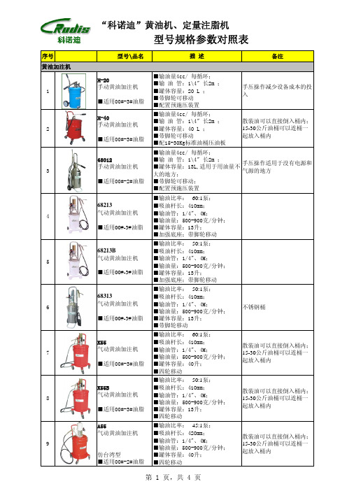
科诺迪黄油机型号规格参数对照表
66110 高黏度黄油加注机
■适用00#-3#油脂
66220 双立柱 高黏度黄油加注机
■适用00#-3#油脂
■气压升降机构;气动预施压装 置; ■适用于20-30Kg(内径260310mm)油桶;随动板φ310mm; ■高压黄油管长4米
■双立柱气压升降机构;气动预施 压装置; ■适用于20-30Kg(内径260310mm)油桶;压油板φ310mm; ■管长4米
■输油管卷盘: 1/4" 、10M;
■适用00#-3#油脂 ■输油量:500-900克/分钟;
■带脚轮移动
19
64200 气动黄油加注套件
■输油比率: 60:1泵; ■吸油杆长:940mm; ■适用于200Kg(内径540-580mm)
油桶
■适用00#-3#油脂
■卷管盘: 1/4" 、10米; ■输油量:500-900克/分钟;
■输油比率: 50:1泵; ■吸油杆长:410mm; ■输油管:1/4"、4M; ■输油量:500-900克/分钟; ■罐体容量:13升; ■带脚轮移动
不锈钢桶
■输油比率: 60:1泵; ■吸油杆长:410mm; ■输油管:1/4"、4M; ■输油量:500-900克/分钟; ■罐体容量:40升; ■四轮移动
散装油可以直接倒入桶内; 15-30公斤油桶可以连桶一 起放入桶内
■输油比率: 50:1泵; ■吸油杆长:410mm; ■输油管:1/4"、4M; ■输油量:500-900克/分钟; ■罐体容量:13升; ■四轮移动
散装油可以直接倒入桶内; 15-30公斤油桶可以连桶一 起放入桶内
■输油比率: 45:1泵; ■吸油杆长:420mm; ■输油管:1/4"、4M; ■输油量:500-900克/分钟; ■罐体容量:40升; ■四轮移动
[2017年整理]挪威DNH水下扬声器AQUA-30
![[2017年整理]挪威DNH水下扬声器AQUA-30](https://img.taocdn.com/s3/m/971be5a768dc5022aaea998fcc22bcd126ff42a9.png)
挪威DNH水下扬声器AQUA-30⏹公司专业做原装进口贸易产品,询价快,出货快,所含的利润少,你买不到的产⏹品,请联系我们!期待您的来电咨询!用最好的服务,提供给客户最优质的产品。
⏹联系王工180******** QQ 1797242860⏹马丁戴克液压油W15-4⏹摩菲排污阀 DVU2120⏹STAFFA骨架密封圈 100-127-13 60675⏹摩菲温度开关20TE-250-10-1/2⏹泰科火焰探头 516.800.007.811F⏹E2S按钮 GNEXCP6BPTDNSDNYB24V⏹E2S按钮 GNEXCP6BPBDNSDNRD24V⏹英格索兰气动马达4840U2⏹德瑞克除泥器PN:10523-12⏹DERRICK除泥器6431-00⏹DYNISCO传感器 PT4624-35MPA-6/18⏹威乐水泵 MHI 204-1/E/1-220-50-2⏹SENSUS减压阀 461REG,SERIAL NO:16190690⏹摩菲温度开关20TE-250-10-1/2⏹SIEMENS 1900336-001⏹ADI R271-FT-GB2-L⏹日本渡边 HNE30-600H-3FAC⏹BETTIS密封圈维修包 62830kit⏹SC047R⏹Metso球阀 5H36HBRT,1寸⏹ALLEGRO ALL2000 14 IN X 16 IN⏹---------------------------------------------------------------------- ⏹---⏹⏹泉州市双环能源科技有限公司,直接与国外厂家联系,货期快,品质保证。
只要⏹你提供品牌和型号,我们就可以帮你们查找询价,欢迎联系,期待与您的合作。
⏹⏹联系人:王小姐⏹手机:180****4738⏹电话:0595-******** QQ:1797242860⏹⏹---------------------------------------------------------------------- ⏹--------⏹美卓电气阀门定位器 ND9106HXIT REV2.3⏹VAL-TEX脚踏式注脂泵 QS-1800A-K⏹Allergro P/N2050-01⏹DEWALT手套DPG20L L⏹DEWALT手套DPG20L XL⏹DEWALT 手套DPG20M⏹ELECTROLYZER SEG-II 020A01⏹MARITIME PROTECTION AS 475⏹VARCO 30122112⏹VARCO 50108-14-C⏹液压油滤清器30173216⏹液压油滤 30173216-1/114416⏹齿轮油滤清器30111013⏹RADIUM GFRMANY 航行灯泡230V ZPD1103⏹泰科报警器 3000-9017-F⏹泰科手动报警按钮 3000-9006-F⏹泰科探测器 3000-9009-F⏹泰科底座 3000-9011-F⏹泰科输出模块 9000-9005-F⏹泰科输入模块 3000-9001-F⏹泰科隔离器 3000-9004-F⏹National油封 415867⏹AROX MOTOR 2955MOTXS 80⏹BOSCH主机喷油嘴调校泵 0681200502⏹CAT 卡特增压器102-0290⏹SKF轴承 20098⏹GRACO高压清洗泵软管 247878⏹GRACO高压清洗泵喷嘴 805422⏹GRACO高压清洗泵喷嘴 805433⏹GRACO高压清洗泵喷嘴 805446⏹GRACO高压清洗泵喷嘴 805450⏹GRACO高压清洗泵喷嘴 805459⏹VAL-TEX脚踏式注脂泵 QS-1800A-K⏹哈威泵 R8.3-8.3-8.3-8.3A⏹日本东空蘑菇头砂轮机 MG-1B气动⏹日本思博电位计 SCP22C⏹丹佛斯压力开关 KP15⏹马兰士对讲机电池 FNB-V57AIS⏹马兰士对讲机天线 HX370SAS⏹ORGA灯泡 CC8 S11⏹DERRICK配件 3660-05-30⏹DERRICK振动筛液压缸 G0005084⏹派克滤芯 G04276⏹猫牌泵 623⏹CLIMAX高压黄油枪NO.10516⏹BW检测仪GASALERTMICROCLIP XT\MC2-XWHM-Y-CN ⏹施乐百RH35B-2EK.6N.2R⏹Hands-off Tool配件SHST2-42⏹Hands-off Tool配件SHST2-72⏹CTA 猫牌蓄能器6014⏹唐纳森 p170546⏹SC056R⏹TIDELAND航标灯NAVIGATIONLAMP\ML-300\TIDELAND\NAVIGATION/03- ⏹德国EBM R2E 250-AS47-05⏹莫尔斯灯CB4060-0088雾笛导航系统/GB-2L⏹DOYLES配件 694493-01D⏹DOYLES配件 44844-06D⏹DOYLES配件 610500-23D⏹DOYLES配件 630691-01D⏹DOYLES配件 21793-11D⏹LEINE LINDE 861900104-1024⏹泰科探头601F-M⏹泰科感温探测器601P-M⏹三菱压缩机 GTC5150ND78A⏹SC047R⏹SPM铜环 4P100650⏹HYDROSEAL 2BV0LN/G5⏹CAT 卡特增压器102-0290⏹三菱压缩机 GTC5150ND78A⏹OTECO Pipe wiper⏹National油封 472951⏹SC064R⏹SUNFAB 轴油封修理包 50666⏹奥克电缆OKONITE 546-31-3453⏹Myers接头 SSTG-1 1/2" NPT HUB⏹TELELECT吊绳 34395A⏹SUNFAB 轴油封修理包 50666⏹SC034R⏹NUFLO 6寸流量计P/N 9A-100009536⏹MILNOR 122200⏹MILNOR 130400⏹VARCO钻铤卡瓦牙 5-1/2”-7”⏹力士乐传感器 900008752⏹DYNALCO传感器M203⏹日本金子 M15G-8-DE12PU\DC24V⏹SUNFAB 泵 SCP047RH-L4-ZTF S10⏹力士乐泵A4VG90EP4D MT1/32R-NSF02F011SH-K⏹SUNFAB 泵 SCP047RH-L4-ZTF S10⏹VARCO电路板 116199-7⏹VARCO油泵电机 109755-2⏹倍加福 NJ5-18GK-SN⏹马丁戴克电池组PN:40219908⏹华高开关 87708-36⏹McDaniel KFP-GF⏹DERRICK筛网TH48-30*0.21MT⏹GARLOCK 油封 53X8630 R2 (22627-8630)⏹LIFTKET整流器SB01200004000040M⏹摩菲温度表A20T-OS-250-25-1/2⏹摩菲显示器 PV101-A-M02⏹SPECK NP25/30-200及NP25/38-180 07.3585⏹SPECK弹簧盖 07.4122⏹CANRIG H15-1004-010⏹BEI配电器(1入1出) ZNA201-PA 24VDC供电⏹BEI隔离器(1入1出) ZNA201-PA 24VDC供电⏹KEB变频器 09F5B1B-3A0A⏹天马接头 IF6310E⏹德瑞克振动筛手压泵 PN:SYB-2⏹ADC7283/24,230VAC4.5A/24VDC 30A,FINLAND⏹STANZOIL手套 NL52337429,MEDIUM⏹西门子6ES7414-4HJ04-0AB0V4.0.10⏹WABCO 4324320230⏹博士继电器 0332209211⏹KEB变频器 09F5B1B-3A0A⏹派克油泵 DP14R-310C⏹NOV顶驱螺栓 50008-14-C5D⏹SPM润滑脂 P13336⏹SOLO SMOKE DETECTOR TESTER PRODUCT CODE SOLO A3-001 ⏹HDI电池 E260⏹NOV接触器 30157674-32-RT,CONTACTOR⏹MEDC声光报警器DB3UL048N2CNR + XB11UL02406RNDNNNR ⏹MEDC手动报警按钮BG2EDC1NR⏹本迪克斯调压阍 T293975-L⏹威创压力传感器 5093BMST85⏹SOR液位开关 1TA-K45-M4-C2A-YY⏹MagTech 液位计 LTM300G-508MM-ATEX⏹CLIMAX10516枪头软管总成 105101 Hose测量学试卷 第 5 页(共 7 页)《测量学》模拟试卷得分 评卷人 复查人1.经纬仪测量水平角时,正倒镜瞄准同一方向所读的水平方向值理论上应相差(A )。
朗克高压油泵系列PC、PD和PS产品说明说明书

CFluid Power Intensifiers Series PC, PD and PScostly way to provide highpressure hydraulic power.■ Maximum Input Pressures:Air - 250 psi (17 BAR);Oil - 1000 psi (69 BAR).■ 3 1/2" to 5 1/2 RAM -3000 psi (206 BAR).■Parker Fluidpower IntensifiersDesigned to Save Energy, Time, Space and Money in a Wide Variety of Applications.A Parker Fluidpower Intensifier is an efficient way of generating high pressure hydraulic fluid. Its operation is quite simple.Pressurized fluid – either air or oil – enters the intensifier and acts on a confined piston. This in turn drives a smaller diameter ram or piston to deliver a given volume of fluid. As a result, the output pressure is intensified and is considerably higher than the input pressure.By using a Parker Intensifier you can save in many ways. First,since it requires only low pressure input and less costly control valving, you eliminate the extra expense of high pressure pumps,valving and a large electrical power sources. The simplermountings and controls also save you valuable installation time.In addition, since Parker Intensifiers produce high hydraulic pressure, you can save space by using a smaller bore hydraulic cylinder in place of a larger bore air cylinder that is heavier and more costly.Finally, because of the rugged dependability of Parker Intensifiers and the simpler circuitry required, you eliminate the constant motion, heat generation and power consumption found in pump systems. This means that you use less energy with less downtime and maintenance.These abilities and benefits of Parker Fluidpower Intensifiers make them the ideal component in many applications. You can use them for such operations as marking, forming, molding,punching, riveting, shearing, straightening, laminating, emboss-ing, welding and testing.What’s more, the Parker Intensifier can be mounted on or off the equipment and can even be integrally combined with the work cylinder. This flexibility makes them particularly useful hydraulic pressure sources on portable equipment.Parker Fluid Intensifiers are available in various sizes andconfigurations. There are cylinder-to-ram units with capability for either single pressure or dual pressure service (left above), as well as several cylinder-to-cylinder models (above right).Here are the features you’ll find in every Parker Fluidpower Intensifier:1. Compact, high-strength steel heads, cap and tie rods meet the most demanding applications.2. Seal by pressure O-rings serve as cylinder body-to-head seals prevent leaks. Thecylinder body is also piloted on the O.D. to insure metal-to-metal contact to support the seals.3. The rugged one-piece iron piston is threaded and Loctited to the ram. Parker Lipseal ®piston seals are used with air;piston rings with hydraulic fluid.4. The driving cylinder body is steel tubing with chrome-plated bore for corrosion-resistance in bore sizes 31/4"through 10". Fiber glass is used on 12" and 14" bore sizes.5. The smooth, wear-resistant surface of the chrome-plated and induction-hardened ram greatly lengthens seal life.6. Static O-ring seals prevent leaks past the O.D. of the glands.Back-up washers prevent extrusion.7. Intensifier operation is speeded up by the free flow of fluid in and out of the unobstructed ports. All high-pressure hydraulic ports are SAE straight thread. O-ring type for leak-proof service.8. Serrated Lipseals ® (Patent 2997318) are self-compensating and self-adjusting to provide leakproof ram seal for both high and low pressure operation.9. For servicing the high pressure ram seals, the pressurechamber is independently secured with studs so it can be easily removed without disassembling the complete intensifier.10. For optimum strength and safety, the pressure chamber wall is made of extra thick steel tubing that is piloted in a counterbore and pressure-welded to the head.This basic circuit is for a dual pressure system supplying pressureto a double-acting work system. The circuit may be readilyA Cutoff ValveB Air Preparation Unit (Filter Regulator Lubricator-Gauge)C 4-Way Valve (Normally 2 Position)D 3-Way ValveTank Fluid Levels)F Advancing Tank (Air-Oil)G Retracting Tank (Air-Oil)H IntensifierI Work Cylinder1234156789810CStep 1: Determine the intensifier ratio for your application. This is the ratio of the available input fluid pressure and the output operating pressure required for the application. For cylinder-to-ram or cylinder-to-cylinder units, use the following formula:Intensifier ratio =Output pressure Input pressureStep 2: Locate the intensifier ratio in column 5 of the appropriate chart on page 3. If the exact ratio is not shown, use the next larger ratio listed. When more than one choice is possible, usually the smallest driving cylinder bore size for a given intensifier ratio is the most economical answer.Step 3: On same horizontal line as ratio determined in Step 2,select the driving cylinder bore size from column 1 and the ram diameter or driven cylinder bore size from column 3.Note: For cylinder-to-ram applications, proceed with Steps 4 and 5. If a cylinder-to-cylinder unit is required, go to Step 6.Step 4: Determine the type of cylinder-to-ram intensifier needed.Generally, a single pressure intensifier is used when the hydraulic work cylinder requires a high pressure for the entire stroke or in test vessel applications. A dual pressure intensifier is recom-mended if the high pressure is to be used only during the last portion of the work cylinder stroke.Step 5: Calculate the intensifier stroke.For single pressure intensifiers, use the formula:Intensifier stroke =V + V cA rFor dual pressure intensifier, use this formula:Intensifier stroke =V h + V cA rWhere: V = Work cylinder volume or test vessel fluid requirementin cubic inches.V h = oil volume in cubic inches required to move the work cylinder piston through its high pressure stroke.V c = compressibility allowance of 1% per 1000 psi of total volume in cubic inches of oil in the high pressure circuit,determined from:V c = total volume x .01 x high pressure/1000.A r = area of intensifier ram in square inches.changed for other operating conditions such as single acting cylinder and single pressure delivery.The input pressure is introduced to the system through shop air lines to the 4-way directional control valve C. When valve C isshifted to position as shown, air is directed into air-oil tank F and to valve D. Oil, acted upon by air pressure, is forced from tank through pressure chamber of retracted intensifier and into work cylinder. The cylinder advances in stroke, being driven by this incoming oil. At a predetermined point in the stroke length of the work cylinder, valve D is synchronized to shift and direct air pressure to the intensifier to drive it in its power stroke, isolating tank F and supplying high pressure to work cylinder for its high thrust stroke. The work cylinder and intensifier are retracted by the shifting of valves C and D simultaneously to exhaust the intensifier and tank F. At the same time, air pressure is directed to tank GHow to Select Parker Fluidpower IntensifiersNote: If the calculated intensifier stroke results in a fraction,correct to the next larger even inch. The recommended maximum stroke is 20". If stroke calculation results in longer than 20" stroke,select a larger driving cylinder and ram having a similar intensi-fier ratio and recalculate stroke.Step 6: For cylinder-to-cylinder intensifiers: Select the properoutput cylinder. Since the output pressure is limited by the cylinder construction, the cylinder should be selected using the maximum pressure to be developed under nonshock conditions.For Parker Series 3L and 2H hydraulic cylinders, the maximum pressures under nonshock conditions are:3L Series:11/2"–2500 psi;2"–2000 psi;21/2"–1800 psi;31/4"–2000 psi;4"–1350 psi;5"–1500 psi;6"–1100 psi;8"–900 psi2H Series: All bore sizes – 3000 psi.General Guidelines1.Intensifiers are generally faster operating when:a. There is adequate input pressure.b. The ports and piping are large enough. Consider the use of oversize ports and connecting lines, to minimize pressure drop.c. The intensifier is pre-exhausted prior to the power stroke.d. Size hydraulic lines so that fluid flow velocity does not exceed 7 feet per second.2.Bypass the intensifier with a pre-fill low pressure line by direct connection through a check valve to the pressure vessel.3.Regulate the driving pressure to the intensifier to achieve the required high pressure output.4.Keep all piping lengths to a minimum by having the tanks,intensifier and pressure vessel as close together as possible.5.A single pressure intensifier usually provides faster cylinder action because it does not need to change from low to high pressure but instead immediately supplies the high pressure.6.Intensifiers are generally used in circuits where limited quantities of high pressure fluid is required.and to rod end side of intensifier piston. Oil from tank G retracts cylinder at low pressure.The operators for valves C and D are optional – mechanical,manual, pilot or solenoid. The method of synchronizing valve D to stroke length position of work cylinder is also optional. This may be done by pilot control, limit switch, pressure switch, mechani-cally such as cams, or manually.*This 2" is the intensifier stroke advance necessary to close the high pressure seal on dual pressure intensifiers only.+ 2"*Fluidpower IntensifiersSelection Sizing(Series PS and PD) Cylinder to Ram Intensifiers1000Col. 11345026404000256040002780204040002940500Col. 102795172513204230261520001280408031252000139010204500288020001470355516154080200Col. 9211411186905283200169210468005125002264416321250800556408381023521800115280058841803200104814221046500032002222163246083200235043563200100Col. 82702105755934526440931600846523400256250113228166254002782043601190511769005764002943385209016001024711523326625001600111181647023600230416001175489931362178160080Col. 7216184644727621132741280677418320205511620001058653500320222163288015249417204613202355122270816721280819569418423126132000128088965337612880184312809405120391925091742128050Col. 61351529280173132204680042326220012831971250661408313200139102180095358845028820014732011693104580051235626226441633125080055640838082351180011528005883200244915681089800IntensifierRatio Col. 527.0210.575.593.452.6440.9316.008.465.234.002.5663.9525.0113.228.166.254.002.782.0436.0119.0511.769.005.764.002.9464.0333.8520.9016.0010.247.115.2352.8932.6625.0016.0011.118.1676.1647.0236.0023.0416.0011.7564.0048.9931.3621.7816.00Area of VolumeD ispl. Per in StrokeCol. 4.307.7851.4852.4053.142.307.7851.4852.4053.1424.909.307.7851.4852.4053.1424.9097.0699.621.7851.4852.4053.1424.9097.0699.621.7851.4852.4053.1424.9097.0699.6211.4852.4053.1424.9097.0699.6211.4852.4053.1424.9097.0699.6212.4053.1424.9097.0699.621Dia.Col. 35/811 3/81 3/425/811 3/81 3/422 1/25/811 3/81 3/422 1/233 1/211 3/81 3/422 1/233 1/211 3/81 3/422 1/233 1/21 3/81 3/422 1/233 1/21 3/81 3/422 1/233 1/21 3/422 1/233 1/2Area Col. 28.29612.56619.63528.27450.26578.540113.10153.94Bore Col. 13 1/44568101214Driving Cylinder Hydraulic RamTheoretical IntensifiedHydraulic Pressure (PSI) UsingAn Input Pressure Of(Series PC) Cylinder to Cylinder Intensifiers1000Col. 112640*4000*2560*4000*2370*3410*2250*14404000*2560*1780*4000*2780*4000*2940*2250*4000*3060*500Col. 10234513203555*200012803125*2000*11854500*2880*170511257203030*2000*12808904735*3125*2000*1390*4500*2880*2000*1470*1125*3920*1725*2000*1530*200Col. 9938528142280051222221250800474180011526824501883200*204812128005123563200*189412508005562728*1800*1152800588*4502450*1568*1090800*612100Col. 846926471140025611116254002379005763412251441600102460640025617816009476254002781364900576400294*2251225784545400*30680Col. 7375211569320205889500320190720461273180115128081948532020514312807585003202231091720460320235*180980227436320*24550Col. 62351323562001285563132001194502881711137280051230320012889800474313200139682450288200147*113613392273200*153Intensifier Ratio Col. 54.692.647.114.002.5611.116.254.002.379.005.763.412.251.4416.0010.246.064.002.561.7816.009.476.254.002.7813.649.005.764.002.942.2512.257.845.454.003.06Area Col. 41.7673.1421.7673.1424.9091.7673.1424.9098.2963.1424.9098.29612.56619.6353.1424.9098.29612.56619.63528.2744.9098.29612.56619.63528.2748.29612.56619.63528.27438.48550.26512.56619.63528.27438.48550.265Bore Col. 31 1/221 1/222 1/21 1/222 1/23 1/422 1/23 1/4452 2 1/23 1/44562 1/23 1/44563 1/44567845678Area Col. 28.29612.56619.63528.27450.26578.540113.10153.94Bore Col. 13 1/44568101214Driving Cylinder Theoretical Intensified Hydraulic Pressure (PSI) UsingAn Input Pressure OfDriving Cylinder *Not recommended for Series 3L driven cylinder, use Series 2H.Cylinder to Cylinder Intensifier – Series PCCFluidpower IntensifiersDimensions and MountingsParker Fluid Power Cylinder to Cylinder Intensifiers (Series PC)Series PC Intensifiers consist of two cylinders joined into an integral unit with one piston driving a second piston of smaller diameter. These intensifiers are not self-bleeding or self-filling, therefore, for the most effective operation, it is recommended that these tasks be done manually.Special Note: It is recommended that Series PCcylinder-to-cylinder intensifiers be mounted vertically with the smaller cylinder up.MTG Styles are:HBA – Air Input HBL – Hyd. InputMounting Style TCCap Tie Rods ExtendedThis mounting available in driving cylinder bore sizes 31/4-inches through 14-inches.MTG Styles are:TCA Cap End – Air Input TCL Cap End Hyd. InputAPSFluidpower IntensifiersDimensions MountingsParker Fluid Power Cylinder to Ram Dual Pressure Intensifiers (Series PD)Series PD Intensifiers are similar to the Series PS units except a center head has been added to retain another gland and a third ram seal. When the ram is fully retracted, it withdraws from this third seal, allowing the low pressure the low pressure hydraulic fluid to flow through the port in the center head. The fluid then goes past the ram and out the pressure chamber port to prefill and advance the work cylinder. Actually, this third seal and the ram act as a check valve. As the circuit sequences, the ram advances into the seal to close this “valve” and build up highpressure. With this arrangement and the proper mounting, Series PD intensifiers are self-bleeding and self-filling. And theseSpecial Notes: 1. When equipped with integral air-oil tanks, Series PD intensifiers have a maximum input pressure of 150 psi.2. It is recommended that Series PD dual pressure intensifiers be mounted vertically with the pressure chamber down.Mounting Style CB –End AnglesMounting Style TBHead Tie Rods Extended(Styles TC – Cap Tie Rods Extended and TD – Both Ends Tie Rods Extended are also available. Dimensions “BB”remains the same in all cases.)Mounting Style TBHead Tie Rods Extended with Integral Air-Oil Tank Mounting Style CB –End Angles with Integral Air-Oil Tanks+CParker Fluid Power Cylinder to Ram Single Pressure Intensifiers (Series PS)Series PS Intensifier delivers a single pressure through a double acting piston driving a ram. One seal on the ram gland works on the driving piston side; the other on the pressure chamber side. Since this intensifier is neither self-bleeding nor self-filling, for best performance it is recom-mended that these tasks be performed manually.Special Note: It is recommended that Series PSsingle pressure intensifiers be mounted vertically withMounting Style CB – End AnglesMounting Style TCCap Tie Rods Extended(Style TB – Head Rods Extended, and TD – Both Ends Tie Rods Extended, are also available. Dimension “BB” remains the same in all cases.)Fluidpower IntensifiersDimensions and MountingsWARNINGFAILURE OR IMPROPER SELECTION OR IMPROPER USE OF THE PRODUCTS AND/OR SYSTEMS DESCRIBED HEREIN OR RELA TED ITEMS CAN CAUSE DEA TH, PERSONAL INJUR Y AND PROPERTY DAMA GE.This document and other information from Parker Hannifin Corporation, its subsidiaries and authorized distributors provide product and/or system options for further investigation by users having technical expertise. It is important that you analyze all aspects of your application, including consequences of any failure and review the information concerning the product or system in the current product catalog. Due to the variety of operating conditions and applications for these products or systems,the user, through its own analysis and testing, is solely responsible for making the final selection of the products and systems and assuring that all performance,safety and warning requirements of the application are met.The products described herein, including without limitation, product features, specifications, designs, availability and pricing, are subject to change by Parker Hannifin Corporation and its subsidiaries at any time without notice.!How To OrderWhen ordering Parker Intensifiers, please specify:a. Quantityb. Driving Cylinder bore sizec. Mounting style – specify by using style letters given beneath dimension drawings.d. Driving cylinder operating fluid mediume. Intensifier series (PS, PD or PC)How To Order Parker Fluidpower IntensifiersModel NumbersEach Parker Fluidpower Intensifier has a model number.This, along with the driving cylinder bore size and stroke,is an accurate and coded description of the unit. The chart When Ordering Fluid Power Intensifiers By Model Numberf. Intensifier ram diameter (for cylinder-to-ram intensifiers)or Output cylinder bore (for cylinder-to-cylinder units)g. Driving cylinder strokeh. Input pressure, output pressure and volumeNote: Standard intensifiers are designed for use with petroleum base hydraulic oil. If other fluids will be used,please consult the factory.here shows the elements of these model numbers. It is provided so that you can check our order acknowledgement against your order.Intensifier Ram (or D riven Cylinder)Diameter Specify From Dimension TablesDriving Cylinder Bore 3 1/4,4, 5, 6,8, 10,12 or 14Driving Cylinder Mounting Style CB,TB, TC,TD, H or HB Driving Cylinder Operating Fluid 2A (Air)or 3L* (HYD.)SpecifyOne SeriesOnlyIntensifier SeriesPD,PS, PC Driven Cylinder Series PC Only 2H (3000 PSI Maximum)or 3L (900 to 2500 PSI Maximum Depending on Bore SizeSpecial FeaturesS Use Only if Intensifier Varies From CatalogDriving Cylinder Stroke Specify For PD Style See Note Below–X NOTE: PD style intensifiers require 2" additional stroke to seal the high pressure end. See Page 61.*3L supplied with cast iron piston rings unless otherwise specified.SpecificationsMaximum Input Pressures:Air - 250 psi (17 BAR); Oil - 1000 psi (69 BAR).Maximum Output Pressures:5/8" to 3" RAM - 5000 psi (345 BAR);3 1/2" to 5 1/2 RAM - 3000 psi (206 BAR).Maximum Operating Temperatures:-10°F to +165°F (-23°C) to (+74°C).。
2018 阿特拉斯·科普柯工业动力材料去除工具说明书

工具名称 136备注产品目录使用指南随机附件此指南,为每种工具及其附件(接头、销和防护装置等)提供了详细参数。
操作手册和备用附件清单也包括在内。
可选附件你可在此可找到绝大多数附件的规格参数。
这些规格参数取决于使用工具的具体工位,并且需要单独订阅。
耗气量工具耗气量的单位为升/秒(l/s),与自由空气相关,即:膨胀为大气压力的压缩空气。
除非另有说明,数据为在6.3bar工作压力下的数值,且为最大耗气量。
最大耗气量在工具不配备调速器进行空转(即工具无负荷运转情况)也适用。
配备调速器的工具,在达到最大功率输出时实现最大耗气量。
速度工具速度单位为转数/分(r/min),显示为空转速度,(若无另外规定)即指工具在无负荷和6.3bar工作压力下的运转速度。
最大输出速度为工具无调速器空转速度的50%和配备调速器后空转速度的80%-90%。
订购维修套件在此标题下,列出了针对相关工具进行的最频繁维修工作的维修套件。
振动及噪音排放参照ISO28927的振动值总是作为测定的振动值和偏差给出。
偏差表示测量时的振动范围。
真实工作情况下,使用中工具振动排放范围至少处于同等幅度,通常会非常大。
在众多典型应用操作中使用工具时,大多数情况下,参考ISO28927给出的振动值也可对使用中工具的振动值进行粗略估算。
使用中工具的振动情况会受到非人为可控因素的影响,其中包括维护不当、盗版部件、不平衡的砂轮等。
在测量噪音时,阿特拉斯·科普柯采用了ISO15744标准。
本目录中给出的数值为测得声压等级。
若测得值超出80dB(A),则还会一并提供声功率级。
标准中还描述了如何计算该数值的方法。
不同测试方法和生产过程中数值的偏差为3dB(A)。
使用中工具靠近操作者耳边的噪音值可能与给定值有显著差异,而且在众多应用中,当操作加工声响高于无负载工具噪声时,情况更加突出。
在超出自身控制工作环境下个人风险评估中,因使用公布值,而非实际暴露值所造成的后果,我们阿特拉斯·科普柯公司概不承担责任。
黄油枪工作原理
黄油枪工作原理
黄油枪是一种用于喷射黄油或其他软质食品物质的装置,通过一定的原理实现将这些物质均匀地喷射到目标表面上。
黄油枪的工作原理主要包括以下几个方面:
1. 压力途径:黄油枪通常具有一个容器,容器内存放着黄油或其他软质食品物质。
当按下黄油枪的扳机时,内部的压力会增加。
这一压力可以通过手动、电动或气动等不同的方式产生。
2. 压力传递:黄油枪内部有一个与喷嘴连接的管道系统,通过这个系统,压力从容器中传递到喷嘴。
3. 喷嘴设计:黄油枪的喷嘴设计非常重要,它决定了黄油或其他软质食品物质以何种方式喷射出来。
通常,喷嘴会具有一定的孔径和形状,以控制喷射的速度和方向。
有些喷嘴还会配备调节阀门,可以调整喷射的量和强度。
4. 压力释放:当扳机松开时,黄油枪中的压力会迅速释放,不再将黄油或其他物质喷射出来。
这可以通过设计喷嘴内部的结构或使用阀门等方式实现。
总的来说,黄油枪通过建立压力、传递压力和控制喷射的方式,实现将黄油或其他软质食品物质均匀地喷射到目标表面上。
它在烹饪、烘焙和装饰等方面具有广泛的应用。
杰斐锋Bobcat 200Air Pak 气压机 生成器 电池充电器 扭转扇 焊接机说明书
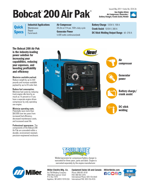
Issued May 2017 • Index No. ED/4.35Welder/generator/air compressor/battery charger is warranted for three years, parts and labor. Engine is warranted separately by the engine manufacturer.Bobcat ™200Air Pak™Gas Engine-DrivenAir Compressor/Generator/Battery Charger/Crank Assist/WelderThe Bobcat 200 Air Pak is the industry-leading power solution for increasing yourcapabilities, reducing your expenses, and boosting profitability and efficiencyMaximize available payload.Reduce weight by up to 550pounds and increase available payload by up to 24 cubic feet.Reduce fuel consumption.Minimize fuel costs by reducing truck engine idle time by as much as 75 percent or if you have a separate engine driven compressor by only operating one engine.Minimize operating costs.Potentially save more than $50,000 over ten years from increased fuel efficiency,decreased maintenance costs, and increased asset life.Professional appearance.The components of the Bobcat 200 Air Pak are concealed within a durable, environment resistant,precision-engineered enclosure.Miller Electric Mfg. Co.An ITW Welding Company 1635 West Spencer Street P.O. Box 1079Appleton, WI 54912-1079 USAEquipment Sales US and Canada Phone: 866-931-9730FAX: 800-637-2315International Phone: 920-735-4554International FAX: 920-735-4125AircompressorGenerator powerBattery charge/crank assistDC stick welding2Legendary ReliabilityTestingRuggedly built and rigorously tested to ANSI and CSA standards, the Bobcat 200 Air Pak is proven to withstand high temperatures, rain, salt, dust, impact, vibration and more. Its welding, auxiliary power, battery charging and crank assist systems are tested to meet the highest applicable industry safety standards.Easy-starting powerWith industry-exclusive eChoke ™* technology, the Bobcat 200 Air Pak starts easily in any weather —and its powerful engine allows simultaneous use of the air compressor with any other feature.*eChoke is a trademark of Kohler Co.Function and Benefit Guide1.Air compressor switch and indicator lights. When the air compressorswitch is in on position, engine runs at 3,600 rpm until set pressure is reached.2.Battery charge and crank assist / generator and weld switch andindicator lights. The top position allows 12-volt battery charge and crank assist. The middle position allows 24-volt battery charge and crank assist. The bottom position allows generator and welding power. 3.Fine weld amperage control 4.Weld range switch5.Battery charge/crank assist receptacle for connection to batterycharge/crank assist (12 or 24 volt). 6.M aintenance display provides fuel level, engine hours and oil changeinterval information.7.Engine control switch is used to start the engine, select speed, andstop engine. In Run/Idle position, engine runs at idle speed at no load and at weld/power speed under load. In Run position, engine runs at weld/power speed.8.120 VAC and 240 VAC receptacles with circuit breakersNote: For matching plug, order 119172.Bobcat ™200 Air Pak ™Features3Performance DataMounting SpecificationsProcess Battery charge/crank assist DC stickRated Weld Output at 104°F (40°C)*Charge: 100 A Crank assist: 300 A150 A at 26 V, 100% duty cycle 180 A at 27 V, 60% duty cycle 210 A at 25 V,20% duty cycleOutput Ranges 12/24 V 50–210 ASingle-Phase Generator Power Continuous/peak 5,500 wattsSound Levels at 7 m (23 ft.)Idle: 66 dB (90.7 Lwa)High speed, no load: 73 dB (98 Lwa)High speed, loaded: 75 dB (100.1 Lwa)NetWeight**558 lb. (253 kg)DimensionsH: 23.76 in. (604 mm)H: 29.78 in. (756 mm) (to top of exhaust)W:20 in. (508 mm)D: 46.64 in. (1,185 mm)*Rated at sea level. **Net weight without fuel.External Mounting A. 20 in. (508 mm)B. 21.77 in. (553 mm)C. 0.88 in. (22 mm)D. 8.21 in. (209 mm)E. 29.86 in. (758 mm)F. 46.64 in. (1185 mm)G. 9/16 in. (14 mm) diameter H. 22.73 in. (577 mm)Internal MountingA. 0.5 in. (12.7 mm) diameterB. 27.48 in. (698 mm)C. 8.88 in. (226 mm)D. 17 in. (432 mm)Certified by Canadian Standards Association to both the Canadian and U.S. Standards.Engine Specifications (Engines warranted separately by the engine manufacturer.)*Fuel stabilizer is recommended for gas engines that are used infrequently.5101520253012345650100150200U .S . G a l./h o u rSCFM (Air Compressor at 175 psi)KVA at 100% Duty Cycle (Auxiliary Power)DC Amperes (Welding)Ordering InformationEquipment Stock No. Description Qty. Price Bobcat ™200 Air Pak ™ 907706 Kohler gas engine with eChoke ™Field Options Options listed below can be added to the above engine drive. Installation is required. GFCI Receptacles 300975Auxiliary Fuel Tank Pump 301450 Air Compressor Oil Heater 301448 Full KVA Adapter Cord 300517Battery Charge/Jump Cables with Plug 300422 25-footTune-Up/Service Kits See above. Order from Miller Service Parts Accessories Running Gear 301460Protective Covers See aboveStick Weld Leads 173851 50 ft., 2/0, 350-amp, 100-percent duty cycle Spectrum ®Plasma Cutters 907529HWY-Mid Frame Trailer 301438 Trailer with lights, fenders and dual hitch. For highway use Cable Tree 043826 Trailer-mounted cable holderDual Hitch 301441 Combination 2-inch (50 mm) ball hitch and 3-inch (76 mm) lunette eye in one reversible assembly2-In-1 Document/Fire Extinguisher Holder 301236 Stores documents and holds a 5-pound fire extinguisherDate: Total Quoted Price:©2017 Miller Electric Mfg. Co.Distributed by:Full KVA Adapter Cord 300517FieldMulti-Terrain Running Gear 301460Includes two heavy-duty Never Flat tires, two 8-inch rubber swivel heavy-duty handle.Recommended for all surfaces and applications,Heavy-duty, water-resistant and mildew-HWY-Mid Frame Trailer 3014381,424-pound (646 kg) capacity highway trailer Genuine Miller ®Options and AccessoriesFemale Receptacle。
perma中文资料

润滑脂
(1)
自定义
时间 和 脉冲 时间 和 脉冲
6
25
-20 +60
250, 500
-
24 25
> 泵
NET
稀油和润 滑脂 (1)
自定义
<600
25
-20 +60
60 – 500
28 29
电驱动且使用稀油的多点润滑系统
ECOSY 稀油 自定义 时间 和 脉冲 6 10 -20 +60 7 l 驱动电机 泵 15-30 V DC 带菜单选 择的显 示屏 -
部件编号 – 连接件
支架、安装底板、安装角铁、延长管、弯头、管接头、软管、铜管、 变径接头、变径管接头、稀油止回阀、油刷、特殊连接件、特殊毛刷、 特殊安装支架、油桶和油瓶(配有部件编号和插图)
40 – 45
1934
坐落于 Bad Kissingen 的家用和 厨房用具金属制品厂建厂
1989
被私人投资集团收购
22 – 29
套件
安装套件:CWL 套件、OGL 套件 基本套件:NOVA, STAR VARIO, STAR CONTROL TIME / STAR CONTROL IMPULSE, PRO MP-6 / PRO C MP-6
30 – 33
GG-60连续喷油空气枪说明书
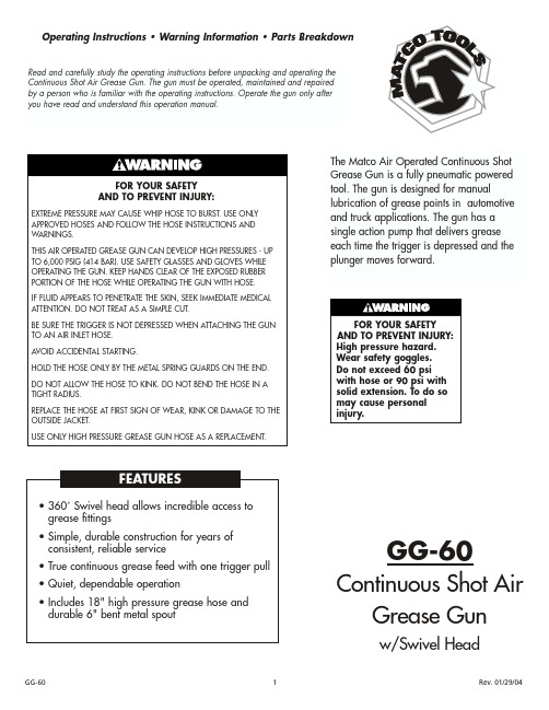
Operating Instructions • Warning Information • Parts BreakdownGG-60Continuous Shot AirGrease Gunw/Swivel HeadRead and carefully study the operating instructions before unpacking and operating the Continuous Shot Air Grease Gun. The gun must be operated, maintained and repaired by a person who is familiar with the operating instructions. Operate the gun only after you have read and understand this operation manual.PRIMING THE CONTINUOUS SHOT GREASE GUNWith the gun loaded with grease and the gun hooked to an air supply, activate the trigger until grease flows from the hose or pipe. To relieve air pockets, operate the air vent valve #31 while depressing the trigger. If grease does not flow after 10-15 seconds of operation, remove the hose or pipe and activate the trigger until grease flows from the hose/pipe outlet. Make sure the bearing, fitting andlubrication line are clear and free flowing before operating the gun. If the bearing, fitting or lubrication line is blocked,the gun can stall.REMOVING AN EMPTY GREASE CARTRIDGE1.Pull the T handle until the rod is fully extended. Hook the rod into the rod notch in the end cap.2.Unscrew the grease tube from the gun.3.Carefully center the grease rod and eject the empty cartridge from the grease barrel.INSTRUCTIONS FOR CARTRIDGE LOADING1.Pull the T handle until the rod is fully extended, lock rod into cap notch and remove the barrel assembly from the gun.2.Remove the plastic cap from the grease cartridge and insert the cartridge into the barrel assembly.3.Remove the pull-tab from the grease cartridge.4.Screw the barrel assembly on to the gun assembly.5.Release the rod by centering the rod.6.Prime the gun and remove any air pockets per the instructions on priming the gun.SUCTION FILLING1.Remove the barrel assembly from the gun.2.Insert the open end of the barrel assembly into the grease bucket.3.Pull the T handle until it is fully to the rear and engage it in the rod notch, making sure to keep the open end of the barrel well within the grease.4.When the barrel assembly is full of grease, screw it back on to the gun assembly.5.Release the rod by centering the rod.6.Prime the gun and remove any air pockets per the instructions on priming the gun.USING A FILLER PUMP1.Attach the bulk load fitting to the bulk container.2.Operate the filler pump.3.When the T handle and rod are fully extended (about 8-1/2"), the barrel is full.4.Remove the gun from the bulk load container.5.Release the rod by centering the rod.6.Prime the gun and remove any air pockets per the instructions on priming the gun.Proper Grease Gun Use...This Air Powered Continuous Shot Grease Gun was developed for the specific purpose of dispensing grease by using pneumatic power.The maximum rating listed below should not be exceeded.This tool should only be used for its designed purpose and according to the instructions in this manual.Specifications...Pump ratio (max)...........................................................40:1Output per stroke..........................................038 in (cubed)Pneumatic inlet pressure (min).....................................40 Psig Pneumatic inlet pressure (max)..................................150 Psig Grease output pressure .........................................6,000 Psig Grease reservoir capacity.........................................14.5 oz.Operating temperature range...............................0 to 120°F Weight (empty).........................................................4.74 lbs Weight (full).............................................................4.84 lbs Lubricant up to NLGI.............................................#2 Grease Pneumatic port inlet..........................................1/4 - 18 NPT Grease port outlet..........................................1/8 - 27 UNPTGeneral Cautionary Notes...Do not allow bystanders, children or other on-lookers in the work area as they can cause distractions, which may lead to mistakes and accidents.Carefully inspect the equipment for damaged, loose or missing parts. If the unit is worn or damaged, do not use it and contact an authorized service center for evaluation or repair.The Continuous Shot Grease Gun must be primed after each refill or grease cartridge change. You should also check the priming of the gun before each use.For best performance and to extend product life, add a few drops of air tool oil through the air fitting at the bottom of the handle if gun begins to cycle slowly or erratically.CAUTION!Air pockets in the cartridge will cause the gun to lose prime.PARTS BREAKDOWN - GG-60*Only Available In RSGG25ASSY Barrel/Follower AssemblyMATCO TOOLS™ 1 YEAR LIMITEDWARRANTY FOR AIR TOOLSMatco warrants its air tools for a period of 1 year to the consumer. We will repair any air tool covered under this warranty which proves to be defective in material or workmanship during the warranty period. In order to have your tool repaired, return the tool to any Matco Authorized Warranty Center, freight prepaid. Please include a copy of your proof of purchase and a brief description of the problem. The tool will be inspected and if any part or parts are found to be defective in material or workmanship, they will be repaired free of charge and the repaired tool will be returned to you freight prepaid. This warranty gives you specific rights. You may also have other rights which vary from stateto state.The foregoing obligation is Matco's sole liability under this or any implied warranty and under no circumstances shall Matco be liable for any incidental or consequential damages.Note: Some states do not allow the exclusion or limitation of incidental or consequential damages so the above limitation or exclusion may not apply to you.。
凯翰锐车辆6條大气机械筒清洗吸气筒系列说明书
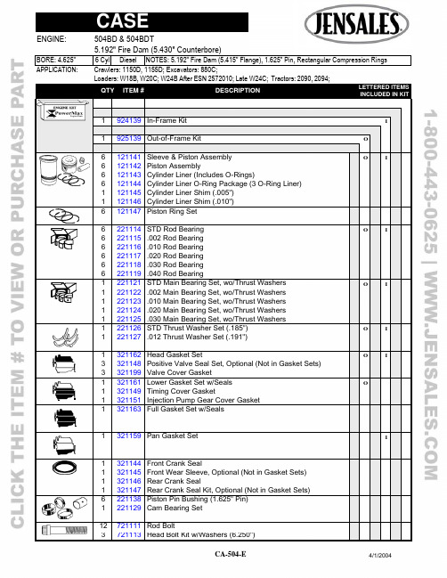
APPLICATION: Crawlers: 1150D, 1155D; Excavators: 880C; Loaders: W18B, W20C; W24B After ESN 2572010; Late W24C; Tractors: 2090, 2094; QTY ITEM # DESCRIPTION LETTERED ITEMSINCLUDED IN KIT1 924139 In-Frame Kit I1 925139 Out-of-Frame Kit O6 121141 Sleeve & Piston Assembly O I6 121142 Piston Assembly6 121143 Cylinder Liner (Includes O-Rings)6 121144 Cylinder Liner O-Ring Package (3 O-Ring Liner)1 121145 Cylinder Liner Shim (.005")1 121146 Cylinder Liner Shim (.010")6 121147 Piston Ring Set6 221114 STD Rod Bearing O I6 221115 .002 Rod Bearing6 221116 .010 Rod Bearing6 221117 .020 Rod Bearing6 221118 .030 Rod Bearing6 221119 .040 Rod Bearing1 221121 STD Main Bearing Set, wo/Thrust Washers O I1 221122 .002 Main Bearing Set, wo/Thrust Washers1 221123 .010 Main Bearing Set, wo/Thrust Washers1 221124 .020 Main Bearing Set, wo/Thrust Washers1 221125 .030 Main Bearing Set, wo/Thrust Washers1 221126 STD Thrust Washer Set (.185") O I1 221127 .012 Thrust Washer Set (.191")1 321162 Head Gasket Set O I3 321148 Positive Valve Seal Set, Optional (Not in Gasket Sets) 3 321199 Valve Cover Gasket1 321161 Lower Gasket Set w/Seals O1 321149 Timing Cover Gasket1 321151 Injection Pump Gear Cover Gasket1 321163 Full Gasket Set w/Seals1 321159 Pan Gasket Set I1 321144 Front Crank Seal1 321145 Front Wear Sleeve, Optional (Not in Gasket Sets)1 321146 Rear Crank Seal1 321147 Rear Crank Seal Kit, Optional (Not in Gasket Sets)6 221138 Piston Pin Bushing (1.625" Pin)1 221129 Cam Bearing Set12 721111 Rod Bolt3 721113 Head Bolt Kit w/Washers (6.250")APPLICATION: Crawlers: 1150D, 1155D; Excavators: 880C;Loaders: W18B, W20C; W24B After ESN 2572010; Late W24C; Tractors: 2090, 2094;QTY ITEM # DESCRIPTION LETTERED ITEMSINCLUDED IN KIT1 929514 Cam Kit: 2090, 2094 C1 929512 Cam Kit: 880C, 1150D, 1155D, W18B, W20C, W24B, W24C C1 929112 Valve Train Kit: 1150D, 1155D, 2090, 2094, W18B, W20C V1 929113 Valve Train Kit: 880C, W24B, W24CV1 929313 Basic Valve Kit B1 521123 Camshaft: 2090, 2094C 1 521111 Camshaft: 880C,1150D,1155D,W18B,W20C,W24B,W24C C1 521119 Cam Thrust Washer1 521121 Cam Thrust Spring1 521112 Camshaft Key C12 521113 Tappet C C6 421128 Exhaust Valve B V V6 421129 Intake Valve B V V12 421113 Valve Guide B V V12 421114 Valve Spring B V V12 421115 Valve Rotator: 1150D, 1155D, 2090, 2094, W18B, W20C V6 421115 Valve Rotator: 880C, W24B, W24C V24 421116 Valve Keeper (Half) B V V6 421131 Exhaust Valve Seat: Except W24B, W24C6 421133 Exhaust Valve Seat: W24B, W24C6 421135 Intake Seat: W24B, W24C (45 Degree)3 421118 Exhaust Rocker Arm, RH Cylinder # 1, 3, 53 421119 Exhaust Rocker Arm, LH Cylinder # 2, 4, 66 421121 Intake Rocker Arm3 421122 Rocker Arm Shaft1 521114 Cam Timing Gear1 521115 Crank Timing Gear1 521116 Idler Drive Gear1 521117 Injection Pump Idler Gear w/Bushing12 521118 Push Rod1 621119 New Oil Pump: Except W24B; W24C w/Turbo1 621146 New Oil Pump: W24C w/Turbo 1 621111 New Oil Pump: W24B1 621112 Oil Pump Shim (.005")1 621117 New Oil Cooler: 1150D, 1155D; W18B, W20C Turbo1 621139 New Oil Cooler: 880C; W18B, W20C Nat Asp; W24B, W24C1 121148 Block Repair Sleeve, Lower Liner Pilot Bore1 721114 Crankshaft1 721115 Plug, Cam (2 3/8")2 821119 Thermostat (180 Degree)1 821122 Block Heater1 821121 Bypass Hose: 880C,1150D,1155D,2090,2094,W18B,W20C1 821137 Bypass Hose: W24B, W24C2 821127 Oil Cooler Hose: 1150D, 1155D12 821128 Turbo Exhaust Manifold Stud24 821123 Intake & Non-Turbo Exhaust Manifold Stud。
卡锐空气冷却器Ck18000产品说明书

Instruction Manual Evaporative Air CoolerCk18000-Portable--Easy to Operate--Low Maintenance-Attention!The following is important information regarding your warranty.Please read before openingand operating your unit.WarrantyWelcome to your new evaporative air cooler. After purchasing this product, please fill out the form below, and mail it to the Cajun Kooling. address within 14 days of purchase.This will ensure you a 1-year warranty on all mechanical parts not including labor. Please check items upon opening and examine for any possible damage, in order to validate your warranty. Please cut on dotted line and mail into the Cajun Kooling address.Your mailed in warranty will be validated according to the date on our copy of your receipt from purchase.Cajun Kooling LA LLC.112 Thruway ParkBroussard, LA 705181-844-819-3557--------------------------------------------------------------------------------------------Customer Name:Customer Address:_____________________________________________________________________Tel. Number: Date of purchase and distributor name:_____________________________________________________________________Model Type: (Circle One)-CK18000Serial Number:(listed on silver sticker on side of unit: ex. )Important Safety InstructionsREAD AND SAVE THESE IMPORTANT SAFETY INSTRUCTIONS BEFORE USING THIS UNITWHEN USING ELECTRICAL APPLIANCES , BASIC PRECAUTIONS SHOULD ALWAYS BEFOLLOWED TO REDUCE THE RISK OF FIRE , ELECTRICAL SHOCK AND INJUURY TO PERSONS ,INCLUDING THE FOLLOWING :1.The unit should always be placed on a firm and flat surface , and at least 10 inches away from the wall .2.The unit should not be use d in a small , enclosed room while using the COOLING function withoutventilation for long periods of time . The air could become saturated and leave condensation on the walls . Leave a door /window partially open when used indoors .3.Before using the unit , check the cord for any signs ofdamage . DO NOT use the unit if the cord has been damaged . Plug into 110v outlets to a void fire or shock hazards .4.The appliance should be unplugged and emptied when not being used for long periods of time . Shut offand unplug the unit before moving . DO NOT tilt while the unit is in operation . Plug and unplug wi th dry hands , and never unpl ug by tugging on cord .5.The COOLING (snowflake ) feature will only operate when water is in the reservoir . Otherwise , the unitwill run as a FAN only . First , fill with water. Then plug in , and then turn on your unit . The cooling will automatically begin and you will see a snowflake light up on the panel . If there is no water in the unit , the cooling will automatically shut off and a red light will appear , indicating that it needs more water . If there is no water , it will not harm the motor and will work properly as a regular fan . This is a safety feature .6.This unitrequires some maintenance ; refer to cleaning instructions for details . 7.This unit is designed for outdoors .However , it can be used indoors in open spaces for short periods oftime . There is no compressor in the unit and will not act as an air conditioner . It is not recommended as adaily household cooling unit , because of the moisture production in smallareas can be harmful .8.Do not insert any object inside the unit without proper care . On ly water and ice should be added . Refer tocleaning instructions for details .9.Do not attempt to repair or adjust any electrical or mechanicalfunctions without consulting Cajun KoolingSupport first . Doing so will void the warranty .10.If you plan to NOT USEthe unit for long periods o f time , drain out all of the water from the reservoirtoensure lifelong durability . Then turn the unit on and run as the F AN function only , for approx . 30 mins .Troubleshooting :Please call Cajun Kooling Support before altering or replacing any parts . Some parts may not need full replacement and can be serviced by a technician . 1-844-819-3557ControlPanelUV Swing Fan Cooling /Pump PowerButton definitionAdd Speed Digital display screen Reduce SpeedSignal window UVON/OFF Cooling FanSwingPar ameter Table Cleaning and Maintenance:1.The Drying Process:For longer lifetime of your evaporative air cooler,after using the unit, it is recommendedto turn off the cooling function (snowflake button) and run the unit as a FAN only for approxim ately 30 mins.This helps to dry out the cooling pads and avoid mildew. The remaining water can be kept in the reservoir for 3more days, but should be changed at least once a week. If storing for longer than one week, drain the waterfrom the reservoir using the drain valve at the bottom of the unit,and then complete the drying process.2.For the Automatic Drying: the timer can b e used as a convenience for you to dry your unit without having tooccupy it. Simp ly turn the snowflake button OFF, keep the fan running, press the timer button on for one hour,and the fan will dry and shut down itself after one hour.3.The reservoir can handle 2oz. of bleach in at least32-gallons of water to refresh the interior. DO NOTput anyother cleaning or foaming products into the machine, because it will foam up the water and over flow your unit.Do not do this more than once a week.4.The black sc reens protecting your cooling pads will collect dust and should be checked at least once a weekwhen using frequently. Pull them out and s imply hose them off or wipe down w ith a wet rag and re-insert. Toavoid build up, DO NOT put chemicals on the screens.The screens should be transparent and you should beabletosee completely through them after they have been cleaned. This ensures complete air intake.5.Cleaning the cooling pads:make sure the cooling pads are dry and the machine is unplugged. Use ascrewdriver to remove the b ack panel of the unit and the cooling pads can easily slide in and out. Rinse softlywith a hose through one side only on low pressure and do not use any chemicals. At an angle, you should beable to see light though the holes once it has been fully cleaned. Re-insert the pads gently and put the backpanel back into place and put the screws back into place.How It Works :This unit is a portable fan , as wells an evaporative air cooler . When using the cooling function , the water inside the unit will be pumped throughout pipes inside , and will be dispersed onto the cooling pads . The motion of the fan will drag air int o the air intake areas , which will then pass through the cooling pads . The movement of the windover the moisture will evaporate and create naturally cool and comfortable air . No mist will be produced . After approx . 8-12 hours , the water reservoir will be completely evaporated into the air and will needto be refilled .Exterior Structurewheel with brakewater tank controllertop coveraxial fanair outletside cooling padwater float water level displaymanual water inletTroubleshooting :Circuit LayoutInstalling TheUnit :1.Lay box down on the back and cut open the bottom from the straps . The wheels will be located in a smaller boxinside of the unit’s box. Open the box of wheels and there should be 4-wheels and 16 screws . Check to makesure that all parts are present .2. Use a screwdriver , gentlyscrew on the wheels and make sure not to strip the screws .3. Stand your box back up and remove the box from the unit by lifting it over the top . Make sure that all parts areintact and correctly assembled .4.You may begin filling water through the water inlet flap using regular tap water . There is a water level in thefront of your unit, located on the reservoir. Be sure not to fill past the “H”, HIGH, level. You will not see the water until it reaches half of the tank on “L”, low, but this level may not need to be reached for yourpreference . Filling at half of the tank will last at least 4 hours of run time .5. If hooking the hose to the hose attachment, be sure that the hose is using low pressure. There is a “float”inside of the water reservoir to stop the water flow when the reservoir becomes full . Hose attachment accessory is in your manual packet .6.Plug in the unit to a safe outlet , and begin using your fan by pressing the Power button . Choose your suitablespeed for your unit and begin enjoying .drain capMatters Need AttentionThis sign means not be allow to do —“Ban ”This sign means please make sure to do —“Enforcement ”This sign means please be careful —“Reminding”!Please review and follow all instructions below to prevent damage asset and people safety.!This machine is suitable for operation indoor.with low humidity.It not allow use this machine in some place with inflammable and explosive gas, prevent direct sunshine on this machine.Do not place the machine on a slope it may cause the machine to topple and damage the equipment inside .Please do not place air inlet of this machine near the wall or window curtain, otherwise it may blocking the air flow, influence the effective cooling and ventilation.When the water container is full , please do not place this machine on aslope or crash it. If want to move it, please push it on flank to prevent the water spill.Only the qualified professional person can take charge the maintain of this machine.!If the supply cord is damaged, it must be replaced by the manufacturer, its service agent orsimilarly qualified persons in order to avoid a hazard.All parts of this machine can not discard casually, not allow throw them into dustbin.。
Atlas Copco GA 355-500 油注射旋筒压缩机说明书

Oil-injected rotaryscrew compressors GA 355-500 (355-500 kW / 450-700 hp)Outstanding performanceGA 355-500 compressors provide high-quality compressed air in the harshest environmental conditions. Incorporating Atlas Copco’s oil-injected screw element, they provide a long and trouble-free life at the lowest possible operating cost.Metal industryQUALITY AND EFFICIENCYMetal plants use compressed air for instrumentation, plant air andpneumatic conveying for raw materials or ash and are in need ofan efficient solution to reduce their operating costs. T hanks to theirinnovative features, our GA air compressors meet this demand.Mining industryROBUSTNESS AND RELIABILITYCompressed air is vital for the mining industry: applications include dustbad filtration, service air, ventilation air and pneumatic tools.The reliability and robustness of GA compressors will accomplishthe job even in the harshest conditions.Power plantsSMOOTH AND COST-EFFECTIVE OPERATIONPower plants run round-the-clock to supply vital energy. A continuoussupply of compressed air is absolutely critical for trouble-free operation.GA air compressors provide a reliable source of compressed air ofapplications such as silt blowing and fly ash handling.General industryA SAFE AND RELIABLE POWER SOURCEMany industrial companies use compressed air in their daily operations.Applications include pneumatic tools for cutting, drilling, hammeringand grinding, pneumatic actuators and valves, ventilation systems,packing and palleting machinery and conveyer systems.GA compressors are designed for ultimate performance and reliability.Keeping your productionup and runningGA compressors ensure long and trouble-free lifetime atthe lowest operating cost. At their heart are state-of-the-art compression elements based on innovative asymmetric rotor profiles and powered by a high efficiency electric motor. Combined with a built-to-last drive system and heavy duty air inlet filters, this results in maximum reliability to operate in the toughest conditions.Reducing your production costsThe innovative design of GA compressors reduces your energy bill and overall compressor lifecycle costs. GA compressorsare pre-assembled packages: installation is fault-free, commissioning time is low and no external instrumentationair is required.Protecting your processThe integrated water separator immediately removes 100% of the condensate, resulting in higher air quality.Maximizing your savingsAs there is no “one size fits all” concept, we have developeda range of features and options to help you optimize the useof your compressor: from running the machine at high temperatures, to extra safety devices.41625Protective air filtration• Protects the compressor components by removing 99.9% of dirt particles down to 3 microns.• Extends the system lifetime3Practical cooler cleaning• Hinged fans, fan motors and cowls for easy cooler cleaning.• Twin fans for optimal cooling.• Axial cooling fans driven by separate T EFC electric motors (IP55 protection).1Superior air quality• 3-step efficient oil separation process for low residual oil content in the compressed air (less than 3 ppm)• Hinged cover for easy separator element change273Moisture separator as standardA cyclonic moisture separator, with automatic and manual drain, mounted as standard, after the cooler block.4Elektronikon unit controller• High resolution color display gives you an easy to understand readout of the equipment’s running conditions.• Clear icons and intuitive navigation provides you fast access to all of the important settings and data.• Monitoring of the equipment running conditions and maintenance status.7T win element on single drive & gear casing• Efficiencies far superior to designs using one large element or 2-stages.• Extended lifetime due to reduced loads on bearings, rotors and gears.• Highly efficient motor – T EFC protection (IP55), class F insulation.5Energy recovery• The optional energy recovery system can recover up to 75% of the compressor’s shaft power as hot water.• The main module of the recovery system is integrated in the compressor.• Recovered hot water can be used as preheated boiler feed water, space heating, showering or other industrial applications.6Optimize your systemWith the GA 355-500, we provide an all-in-one solution incorporating the latest technology in a built-to-last design. T o further optimize the performance of your GA or to simply tailor it to your specific production environment, optional features are available.Additional features & optionsStandard scope of supplyGA 355-500 Flow DiagramIncoming air Air OutAir InOutgoing air Air/oil mixture Water OilTechnical specificationsA = air-cooledW = water-cooled LV = low voltageMV = medium voltageGA 500 figures are for medium voltage IP 23 motor. Reference conditions:Absolute inlet pressure 1 bar (14.5 psi)Intake air temperature 20°C (68°F)Cooling medium temperature 20°C (68°F)(1) Unit performance measure according to ISO 1217,Annex C, Edition 4 (2009), FAD is measured at thefollowing working pressures:• 100 psi variants at 100 psi• 125 psi variants at 125 psi• 150 psi variants at 150 psi• 200 psi variants at 193 psi2) Noise levelA-weighted emission sound pressure level at the workstation, Lp WSA (re 20 μPa) dB (with uncertainty 3 dB).Values determined according to noise level test code ISO2151 and noise measurement standard ISO 9614.(3) Water-cooled modelsGA 500 figures are for medium voltage IP 23 motor. Reference conditions:Absolute inlet pressure 1 bar (14.5 psi)Intake air temperature 20°C (68°F)Cooling medium temperature 20°C (68°F)(1) Unit performance measure according to ISO 1217,Annex C, Edition 4 (2009), FAD is measured at thefollowing working pressures:• 7.5 bar variants at 7 bar• 8.5 bar variants at 8 bar• 10 bar variants at 9.5 bar• 13 bar variants at 12.5 bar(2) Noise levelA-weighted emission sound pressure level at the workstation, Lp WSA (re 20 μPa) dB (with uncertainty 3 dB).Values determined according to noise level test code ISO2151 and noise measurement standard ISO 9614.(3) Water-cooled modelsHW LCOMMITTED TO SUSTAINABLE PRODUCTIVITY2935 0368 20 © 2017, A t l a s C o p c o , B e l g i u m . A l l r i g h t s r e s e r v e d . D e s i g n s a n d s p e c i fi c a t We stand by our responsibilities towards our customers, towards the environment and the people around us. We make performance stand the test of time. T his is what we call – Sustainable Productivity.。
气动高压黄油枪的工作原理
气动高压黄油枪的工作原理气动高压黄油枪是一种通过气动力来提供高压黄油的工具。
它主要由气动泵、背压阀、液压管路以及注油枪等组成。
下面将详细介绍气动高压黄油枪的工作原理。
首先是气动泵的工作原理。
气动泵是气动高压黄油枪的动力来源,通过压缩空气产生压力来驱动黄油的注入。
气动泵通常由压缩空气进气管、活塞、阀门和出口组成。
压缩空气进入气动泵的进气管,通过进气管进入气动泵内部。
进气管上有一个阀门,进气管上的阀门关闭时,空气不能进入气动泵内部;而当进气管上的阀门打开时,空气就可以进入气动泵内部。
当进气管上的阀门打开时,空气进入气动泵内部。
气动泵内部有一个活塞。
当空气进入气动泵后,活塞就会开始运动。
而活塞的运动产生的压力会驱动黄油的注入。
在活塞上还有一个阀门。
当活塞运动时,阀门打开,活塞下沉;而当活塞停止运动时,阀门关闭,活塞上升。
通过活塞上下运动的循环,可以形成一定的压力。
根据实际需求,可以通过调节进气管上的阀门来控制气动泵的工作压力和流量。
然后是气动高压黄油枪的背压阀。
背压阀是气动高压黄油枪中的一个重要组成部分,其作用是控制黄油的流动以及保持黄油的流动压力。
背压阀通常由阀体、活塞、弹簧和阀芯等部分组成。
背压阀安装在气动泵和液压管路之间。
当黄油在液压管路中流动时,会受到一定的阻力。
而背压阀可以通过调节活塞的位置来改变黄油的流动阻力。
调节背压阀的位置可以改变黄油的流动速度和压力。
另外,背压阀还可以起到保护气动高压黄油枪的作用。
当黄油流动阻力过大时,背压阀可以自动关闭,避免黄油流过大导致设备损坏。
最后是黄油的注入。
经过气动泵和背压阀的作用,黄油会被推入液压管路中。
液压管路连接到注油枪上,通过注油枪可以将黄油注入到需要润滑的设备中。
注油枪通常由注油口、手柄、黄油余量显示器和触发器等组成。
当使用者按下触发器时,黄油会被推出注油口,注入到设备中进行润滑。
综上所述,气动高压黄油枪的工作原理是通过气动泵产生压力,通过背压阀控制黄油的流量和压力,最后通过注油枪将黄油注入设备中。
直流重型黄油枪[发明专利]
![直流重型黄油枪[发明专利]](https://img.taocdn.com/s3/m/9ca68831195f312b3069a5a7.png)
专利名称:直流重型黄油枪
专利类型:发明专利
发明人:赵凤玉,董猛
申请号:CN200510025715.3申请日:20050510
公开号:CN1707150A
公开日:
20051214
专利内容由知识产权出版社提供
摘要:本发明涉及一种重型黄油枪,尤其指一种18V直流重型电动黄油枪。
其由外插式电池包提供直流电源,驱动大功率真流电机,由三级行星齿轮和直齿轮减速,增大电机输出扭矩,带动曲柄滑块机构,由此完成电机转初转动成滑块往复直线运动,同时带动柱塞作往复运动,并与供油系统协同,完成黄油枪高压注油的功能。
具有省力、快速、操作方便、压力高、流量大的性能。
申请人:赵宏武,赵凤玉
地址:211402 江苏省仪征市十二圩通江西路8号
国籍:CN
代理机构:上海新天专利代理有限公司
代理人:邬震中
更多信息请下载全文后查看。
- 1、下载文档前请自行甄别文档内容的完整性,平台不提供额外的编辑、内容补充、找答案等附加服务。
- 2、"仅部分预览"的文档,不可在线预览部分如存在完整性等问题,可反馈申请退款(可完整预览的文档不适用该条件!)。
- 3、如文档侵犯您的权益,请联系客服反馈,我们会尽快为您处理(人工客服工作时间:9:00-18:30)。
CLIMAX高压黄油枪10516
CLIMAX润滑脂750-S
(询—李、工:1 5 8 0 5 0 6 1 2 1 3)
CLIMAXCLIMAX102-SWS
CLIMAX黄油枪10516
CLIMAX密封脂3256666
CLIMAX注脂枪10516-SC
CLIMAX润滑脂900M-S
CLIMAX注脂枪1699
CLIMAX润滑脂1034MT-J
德国WEH 加注枪C1-111066 TK17
Alemite 黄油枪325540-1 黄油枪325540-2
V AL-TEX 清洗液VF-CTN 润滑脂80-H-J 密封脂2000-S-P 手动注脂枪1400 脚踏注脂枪QS-1800A-K 电动注脂枪QS-2200A Nordstrom 注脂枪400-D 气动注脂机Hypregun-Plus 5Q 555通用型气动泵阀门注入密封脂
SEALWELD 润滑脂S-EQ-SGC 清洗液S-VCP-SGC 密封脂
S-TL-SGC
lubchem 润滑脂50400HV-10
SerckAudco 气动注脂泵10-90 润滑密封脂733 工具包D-FW-KIT-06 DELTA 注脂枪1699-09
线圈018F6176 世伟洛克手动弯管器
MS-HTB-6M 丹佛斯线圈018F6176 德瑞克SGX55-15-380V/400-5-001
ZP616A10RB00X02 PVH131R13AF30B252000002001AB010A
MS-HTB-12M 富士可编程控制器 NW0P30R-31ZSPE 德国ENCHNER传感器
RPS3131PR175M VZO 25 RC 130/16-RV
意大利variscoJS1-110自吸泵诺蒂菲尔感烟探头FSP-851 P2475RLV AUTRONICA 探测器BHH-200 MAC电磁阀 56C-63-121BA
CAS-724-7+FLA-644-1 德鲁克连接管套件 GE-610-100 AS32061A AS32060B Italvibras电机 CDX 15/3810
A1OVSO45DFR131R-PPA12NOO.0902001693 BIERI溢流阀
PDV700-6-P-700-2-P-A*00 ROSS电磁阀 D2776B4011
EMCO 连接器 J451-05 OBL MD521pp 227-9920 235-1071 CALZON卡桑尼
MR1100G-D1B1N1N1N1000/34852 Bez-Nr.010
IPV6-125 or IPV7-125 安费诺62IN-16JC-10-6S 1245 6SE7038-6GK84-1GG0 6SE7041-8GK85-0HA0 DPI880
6SY7000-0AB18 6SX70100FF05 6SY7010-0AB66 6SY7010-0AB65
P.0141110004 01.07
Consilium marine手动火灾报警按钮\DC 24V\NS-CP-IP55
Consilium marine手动火灾报警按钮NS-CP-TP55
Consilium marine手动火灾报警按钮MCP-C IP67 Manual Call Point 5200014-01A
PARKER派克压力传感器SCP01-016-44-07
WOODWARD多功能电量表LR21296/UMT111/A6
Flexball DZ80/G=2650/HUB95
派克节流阀F1200B
Deif PPU/2/GS
荧光灯应急充放电模块BHD65U
哈威PMVP4-43/G24
哈威SGZW-NUH
Controlli 品牌电动执行器MVF515 24V 50/60Hz 24VA
Controlli 品牌电动执行器MVE515 24V 50/60Hz 24VA
悬吊创伤保护安全带凯比特/Capital 9501403
QUALITROL油流指示器CAS-724-7+FLA-644-1 092-300-01
哈威SB4C
bei NPEXA-CM3D11
胜佰德潜水泵SMA3-A
胜佰德潜水泵SMA3-6AM1
DAB K55/200T-54
马丁戴克机械压力仪表M365-ORD-02-B
得逻辑手持终端7527C-G3
意大利戴纳密克(Dinamicoil)减速机型号 RE8004
哈威泵R1.0
滤芯p556916
SPM p100343
SOR索尔仪表式压力开关4NN-K4-N4-C2A 2-25PS1/1/ZMPT(F)
SPM p100343HP
SPM p100342
SPM p100342HP
SPM p100653
SPM p100653HP
SPM p100652
SPM p100652HP
SPM P100108
SPM 2A18192
SALICRU.S.A交流稳压电源型号RE 1009-2\230VAC
巴鲁夫开关BES M08MH1-NSC15B-S04G
SPM 2A18796
SEVERN TRENT DE NORA垫片 55511-S-T
WESTLOCK终端版 B-EL-40109-050
HEATEX加热器 RFA616A(S9*******)
SEVERN TRENT DENORA密封板 22267
GOODALL RUBBER软管50 FT LENGTH, 3/4 IN DIA, 300 PSI, BLUE event engineering配件 330042
event engineering配件 330075
event engineering配件 330074
DEWALT DPG20XL
SEVERN TRENT DENORA阀 SD007345-21
SEVERN TRENT DENORA电解槽 OMNICLOR-B02C
ROXTEC支架框 G 6X1 PRIMED
ROXTEC备件包 WEDGE KIT GALV
ROXTEC插入模块 RM40
ROXTEC插入模块 RM30
ROXTEC插入模块 RM20
DNH防爆喇叭 DSP-25EExmN(T)
SPM润滑脂 P13336
ORGA 34b00800 P/N.010085
Nordstrom 注脂枪Hypregun-Plus 5Q
sylvania 吊车用汞灯 LU400/ECO 400W S51
SOLA 24V电源 10A SDN 10-24-100C
SOLA 24V电源 20A SDN 20-24-100C
SOLA 冗余电源 20A SDN 2.5-20 RED
SOLA 冗余电源 40A SDN 30/40RED
DNH 扬声器 HS-8EEXMNT
VAL-TEX配件P/N:VF-CTN
Dynisco压力显示表 1480-4-1-0-0
博世雨刮器电机 0390507503
博士电机 0392003065
博士电机 9580234005
33 熔断器 122627-49 250V 2A
34 急停按钮30087708-67 按钮头:CR104PTR20A0R91(红色)+CR104PXC01R(NC)+CR104PXC10R(N0)
35 指示灯 87708-38 24VDC
36 指示灯 30087708-40 24VDC
37 指示灯 30087708-48 24VDC
38 按钮 30087708-02 按钮头:CR104PBG00B1+CR104PXC10R
39 转换开关30087708-33 (不自复位)3位开关头:CR104PSG84B+CR104PXC01R(NC)+CR104PXC10R(N0)A
40 转换开关30087708-30 (自复位)3位开关头:CR104PSG94B+CR104PXC01R(NC)+CR104PXC10R(NO)A
41 电位器 81736-2 10K 2W
42 电源板 96290 5V 电源板 VARCO顶驱配件
43 编码器 115299 PART NO:924-01002-7726 :EE020460 :115299 VDC IN 5-15
44 防爆插头 110022-1R 红色
45 防爆插头 110022-1W 白色
46 防爆插头 110022-1B 黑色
47 储能器修理包 87605-1 序列号54883109
48 空调电机 30155030-5 208/230V 50/60HZ 825转/分 AMP2.5 CAP15 MFD 370VAC TYPE:U28B1
49 109858-1AN VARCO顶驱配件
50 94522-1EN VARCO顶驱配件
51 107029-175N VARCO顶驱配件
52 94520-1AN VARCO顶驱配件
53 94520-1NN VARCO顶驱配件
54 减压溢流阀 99353-1AN VARCO顶驱配件
55 111664-1EN VARCO顶驱配件
56 107031-1AN VARCO顶驱配件
57 94536-230N VARCO顶驱配件
58 94536-14N VARCO顶驱配件
59 93667-M13 VARCO顶驱配件
60 93667-M11 VARCO顶驱配件
61 94537-130N VARCO顶驱配件
62 94534-1CXN VARCO顶驱配件
63 107028-1ANB VARCO顶驱配件
64 93024-4SAE VARCO顶驱配件
65 93024-6SAE VARCO顶驱配件。