Amadeus5手册
Oracle Hospitality OPERA 5 接口说明书

Oracle® Hospitality OPERA 5Validated InterfacesF23596-08October 2023Copyright © 2023, Oracle and/or its affiliates. All rights reserved.Interfaces with OPERA Cloud are now published on Oracle Cloud MarketplaceOracle® Hospitality OPERA 5Validated InterfacesF23596-08October 2023Copyright © 2023, Oracle and/or its affiliates. All rights reserved.This software and related documentation are provided under a license agreement containing restrictions on use and disclosure and are protected by intellectual property laws. Except as expressly permitted in your license agreement or allowed by law, you may not use, copy, reproduce, translate, broadcast, modify, license, transmit, distribute, exhibit, perform, publish, or display any part, in any form, or by any means. Reverse engineering, disassembly, or decompilation of this software, unless required by law for interoperability, is prohibited.The information contained herein is subject to change without notice and is not warranted to be error-free. If you find any errors, please report them to us in writing.If this software or related documentation is delivered to the U.S. Government or anyone licensing it on behalf of the U.S. Government, then the following notice is applicable:U.S. GOVERNMENT END USERS: Oracle programs, including any operating system, integrated software, any programs installed on the hardware, and/or documentation, delivered to U.S. Government end users are "commercial computer software" pursuant to the applicable Federal Acquisition Regulation and agency-specific supplemental regulations. As such, use, duplication, disclosure, modification, and adaptation of the programs, including any operating system, integrated software, any programs installed on the hardware, and/or documentation, shall be subject to license terms and license restrictions applicable to the programs. No other rights are granted to the U.S. Government.This software or hardware is developed for general use in a variety of information management applications. It is not developed or intended for use in any inherently dangerous applications, including applications that may create a risk of personal injury. If you use this software or hardware in dangerous applications, then you shall be responsible to take all appropriate fail-safe, backup, redundancy, and other measures to ensure its safe use. Oracle Corporation and its affiliates disclaim any liability for any damages caused by use of this software or hardware in dangerous applications.Oracle and Java are registered trademarks of Oracle and/or its affiliates. Other names may be trademarks of their respective owners.Intel and Intel Xeon are trademarks or registered trademarks of Intel Corporation. All SPARC trademarks are used under license and are trademarks or registered trademarks of SPARC International, Inc. AMD, Opteron, the AMD logo, and the AMD Opteron logo are trademarks or registered trademarks of Advanced Micro Devices. UNIX is a registered trademark of The Open Group. This software or hardware and documentation may provide access to or information about content, products, and services from third parties. Oracle Corporation and its affiliates are not responsible for and expressly disclaim all warranties of any kind with respect to third-party content, products, and services unless otherwise set forth in an applicable agreement between you and Oracle. Oracle Corporation and its affiliates will not be responsible for any loss, costs, or damages incurred due to your access to or use of third-party content, products, or services, except as set forth in an applicable agreement between you and Oracle.。
Focus-5 生成器指南说明书

GeneratorsA Focus-5 guide to help you decide what’s right for you!1. Size really mattersThe most important thing to consider when sizing a generator is the high inrush currents associated with starting electric motors and transformers, which are typically six times the full load current. However, inrush currents for the type of high-efficiency motors being specified today can be almost double that amount.As a result, it has been common practice to take motor and transformer starting kVA requirements as a yardstick to determine the size of a generator. This approach often results in generators being oversized for the motor running load and not based on the actual needs of the application. Moreover, it disregards other key factors that play a key role in sizing generators. For instance, harmonics caused by variable frequency drives and sequential starting of motors.When starting motors or transformers, large voltage and frequency dips can also occur if the generator set is not sized properly. Furthermore, other loads connected to the generator output may be more sensitive to voltage and frequency dips than the motor or motor starter, which can cause problems.Thankfully help is at hand. Many generators can now be equipped with solutions to overcome the extra excitation systems required in the alternator. Typically, two options are offered: permanent magnet or auxiliary winding. Both provide the generator with three times their nominal current to cover inrush peaks from the electrical motor, for a minimum duration of ten seconds, via a residuary excitation current.In certain cases even more advanced options are available. For instance, some generators feature a digital automatic voltage regulator (D-AVR) that is specifically designed to handle the high inrush currents associated with starting motors and transformers. In specific applications, this type of voltage controller allows operators to downsize the generator requirement because the transient behaviour of the power is better managed. Another option could be to use a “Close Before Excitation” system that closes the breakerjust when engine starts to run. This enablesthe excitation to increase gradually as thespeed of the engine does, allowing for verysoft start of loads connected to the generator. This is especially useful for magnetising stepup transformers in installations where medium voltage is required.As a result, it is no longer necessary to buy larger generators than needed just to cope with the initial electrical surge upon starting. What’s more, with smart control of the generator’s voltage, itis possible to achieve lower fuel consumption, reduced maintenance cost and longer lifetimes. 2. Modular capabilityEven if starting off with just one unit, it’s worth asking the equipment manufacturer what steps can be taken to parallel a single generatorwith others to form a modular power plant set up. For instance, is the generator equipped with this capability as standard? Also, how long would it take to pair two units? With many generators, this process can take under 10 minutes, but not all offer this capability. Therefore, it is strongly recommended to check before an investment is made, in case this capability is needed in the future.When coordinated by a network of controllers, plug-and-play generators can power up and down according to the on-site power requirements at any given time. For example, only one or two may be operational during periods of low load, thereby boosting fuel efficiency. Equally, all units may become active in periods of high demand.There are a number of additional benefits from modular capability. Firstly, equipment reliability is enhanced as the failure of a single unit is mitigated by configuring the remaining unitsto increase their output to maintain the same power output. Secondly, the cost and length of service intervals is reduced, as it isn’t necessary to stop the entire power delivery during essential maintenance operations.3. Control systems and power managementThe ideal control system should offer a variety of features. For instance, the ability to remotely start and program the machine, display warnings, for instance low fuel and other performance issues, in addition to deliver a broad range of analysis data. This helps to better utilise the efficiencyof the power plant while providing a valuable overview of the application process.Many generators are now equipped with Power Management Systems (PMS). What makes them ideally suited for rental applications is the plug-and-play design that allows for easy and rapid configuration. PMS provides the means to optimise the fuel consumption and performance of generators in parallel with load demand,SIMPLE PARALLELING CAPABILITYREDUCED MAINTENANCE TIMEAND COSTSstarting and stopping units with corresponding increase or decrease of load. It also helps avoid engine damage to generators from running with low load levels, thereby increasing their useful work life.4.Fuel efficiency and autonomyThanks to a number of design innovations and energy efficiency improvements, today’s mobile generators now consume much less fuel than was possible five years ago. The fact that the latest equipment can run for longer and more economically has been a big driver behind the market’s growth. However, not all generators are the same and fuel can be expensive.Therefore, it is recommended to ask two or three manufacturers for a forecast on fuel consumption before making an investment.Furthermore, modularity also contributes to fuel efficiency. For example, taking the demand patterns of a typical industrial application as a guide, the deployment of a 1 MVA generator as a prime power source could mean up to 1.677 litres of fuel being consumed each day. That compares with approximately 1.558 litres of fuel if three 325 kVA generators were doing the same job. In this case, an estimated annual fuel saving of €30.000 makes for a compelling case, not to mention 85 tons of CO 2 saved over the course of a year.The options for fuelling generators are expanding nowadays and now include bio-gas and natural gas. Although this market is emerging, it is important to discuss these technologies with a manufacturer before investing in a new generator.5.Physical size and transportationIt pays to determine whether units can be towed or loaded on a truck and to check for features such as lifting eyes and forklift slots. When using multiple generators, it’s also worth considering if units can be stacked on top of each other for minimum footprint and access considerations. These factors have a bearing on total operationexpenditure and efforts to reduce carbon costs.0 00 © 2018 A t l a s C o p c o P o r t a b l e E n e r g y A l l r i g h t s r e s e r v e d .® A t l a s C o p c o i s a r e g i s t e r e d t r a d e m a r k o f A t l a s C o p c o A B。
阿特拉斯GX2-5使用手册

ASE5A 数控交流伺服控制系统 使用说明书

5501E数控交流伺服控制系统使用说明书·在使用本产品之前,请先阅读《操作手册》及所搭配的缝纫机机械说明书。
·本产品必须由接受过专业培训的人员来安装或操作。
·请尽量远离电弧焊接设备,以免产生的电磁波干扰本控制器而发生误动作。
·请不要在室温45℃以上或者0℃以下的场所使用。
·请不要在湿度30%以下或者95%以上或者有露水和酸雾的场所使用。
·安装控制箱及其他部件时,请先关闭电源并拔掉电源插头。
·为防止干扰或漏电事故,请做好接地工程,电源线的接地线必须牢固的方式与大地有效连接。
·所有维修用的零部件,须由本公司提供或认可,方可使用。
·在进行任何保养维修动作前,必须关闭电源并拔掉电源插头。
控制箱里有高压危险,必须关闭电源五分钟后方可打开控制箱。
·本手册中标有符号之处为安全注意点,必须注意并严格遵守,以免造成不必要的损害。
安全事项第1章产品安装1.1产品规格品型号ASE5A电源电压AC220±20%V电源频率50Hz/60Hz最大输出功率550W1.2接口插头的连接将脚踏板及机头的各连接插头安插到控制器后面对应的插座上,各插座名称如图1-1所示,各插座名称如图1-2所示。
连接好,请检查插头是否插牢。
图1-1ASE系列控制器图①抬压脚电磁铁插座;②自动电磁铁插座;③脚踏板插座;:使用正常的力量插不进去时,请检查插头与插座是否匹配,插入方向或针的方向是否正确!图1-2控制器接口定义1.3接线与接地必须要做好系统的接地工程,请合格的电气工程人员予以施工。
产品通电及投入使用前,必须确保电源插座AC 输入端已安全可靠的接地。
系统的接地线为黄绿线,该地线请务必可靠连接至电网安全保护接地上,以保证安全使用,并可防止出现异常情况。
:所有电源线、信号线、接地线等接线时不要被其它物体压到或过度扭曲,以确保使用安全!第2章操作面板使用说明2.1操作面板的显示说明图2-1操作面板外观界面图标描述图标描述软启动功能开关键自动剪线功能开关抬压脚模式切换键上下停针位置选择进入参数和返回键一键恢复到保存参数进入菜单键键确认键亮度调节键左右加减键,首界面+—为速度增减2.2操作面板各按键功能说明序号外观名称功能描述1剪线和慢启动开关1,短按此键开关剪刀。
马自达MX-5维修维修手册

汽车技师帮技术资料
马自达MX-5维修维修手册(1956-7C-08) 概述
• 根据不同的位置: — 应该在某些特定的部位应用密封剂或/和衬 垫。如果涂抹了密封剂,那么应该在密封剂硬 化前安装零部件,从而避免漏泄。 — 应该在零部件的运动组成部件上涂抹润滑油。 — 在重新组装之前,应该在规定的部位 (比如: 油封)涂抹指定的润滑油或油脂。
HO2S
IAC IAT KS MIL
SAE 标准 名称
风扇控制 通用燃油 四档 发电机 接地
加热式氧气传感器
怠速空气控制 进气温度 爆震传感器 故障指示灯
#1:诊断故障码取决于诊断测试模式。 #2:由 PCM 控制 #3:控制发动机和动力传动系的装置 #4:直接与排气歧管连接
End Of Sie
缩写
ᰒ冫⊍㛖ㄝⱘ⍖ᢍԡ㕂
ᰒ冫ৃᠽሩ䚼ӊ
4
94—116 {9.5—11.9, 69—86}
SST 3 5
6
SST
R ⊍㛖
ᰒ冫㓈ׂখ㗗䇈ᯢ
ᓔষ䫔
㶎↡
ϟ㒉㞖⧗ㄐϛ㡖
খ㾕ϟ㒉㞖⧗ㄐϛ㡖ᢚौ䇈ᯢ
㶎ᷧ
ϟ㒉㞖
䰆ᇬ༫ ϟ㒉㞖
ᰒ冫䆺㒚䇈ᯢ
2 118—156 {12.0—16.0, 87—115} 1R
拆卸、拆分过程中的检查
• 在拆卸零部件时,应该仔细检查是否存在故障、 变形、损伤和其它问题。
00
零部件的放置 • 所有被拆分的零部件应该小心放置,以便重新组 装。 • 需要更换的零部件与需要再次使用的零部件应分 别放置或作好标记。
零部件的清洗 • 对于所有需要再次使用的零部件,应采用适当方 式认真彻底清洗。 警告 • 使用压缩空气可能导致灰尘和其它微粒溅 出,从而对眼睛造成伤害。使用压缩空气时 应佩戴眼睛防护用具。
新简单AMADEUS5

AMADEUS5门禁软件使用说明1.软件安装双击门禁光盘English文件夹中的INSTALL.BAT文件弹出下面的窗口:选择English,安装完成后再进行汉化,点击确定后点击下一步弹出窗口选择门禁软件安装的目录,默认的是C:\Program Files\Amadeus5如果需要更改安装目录点击Browse点击Next弹出下面的窗口:这个窗口里有两个选项如果你安装的是服务器选择SERVER如果安装的是客户端选择Workstation选择完后点击Next弹出下面的窗口:在这个窗口里可以选择数据库类型一个是 Microsoft Access数据库,另一个是Microsoft SQL Server数据库(默认的是ACCESS数据库),如果你要安装SQL 版,在安装过程中请选择Microsoft SQL Server,认证模式,认证模式与数据库认证模式相同,密码与SQL数据库的相同,点击Next直到安装完毕。
2.系统调试双击桌面Amadeus5如下图标:(新版本与老版本)或弹出下面的认证窗口:User name: dds Password: dds进入软件主界面窗口:选择Tools下的Options弹出下面界面窗口:选择Language 下的Chinese点击OK软件更改成中文。
(新版本软件提示重启软件)。
3.软件设置3.1通讯回路参数------控制器网络:弹出以下窗口在这个界面里选择通讯方式。
(COM、 TCP、 MODEM)通讯口选择TCP需要注意IP地址后面的冒号(英文输入法下输入),冒号后面端口(1001)与TCP模块端口相同。
TCP模块包括(VDS100、UDS1100、Tibbo)3.2添加控制器参数------控制器:弹出以下窗口点击(新的)按钮在“名称”(默认的是控制器001)可以更改名称,在控制器地址栏里输入地址(软件地址与硬件地址相符)在一条回路里控制器地址不能相同,在控制器类型里如果控制器芯片上贴着(-5047或-5049)选择TPL4门禁,如果控制器芯片上贴着(-6047或-6048)选择TPL4D4门禁.然后点击存储。
Amadeus5手册

让知识带有温度。
Amadeus5手册AMADEUS5用户使用手册20221软件安装挑选English,安装完成后再举行汉化,假如您要安装的是ACCESS server版举行默认安装即可,假如你要安装工作站,在安装过程中请挑选Workstation(默认是Server)。
假如你要安装SQL版,在安装过程中请挑选Microsoft SQL Server(默认是Microsoft ACCESS),认证模式挑选SQL Authetication,密码与您安装SQL时的相同。
安装完毕后进入登陆界面,用户名、密码均为dds,进入软件后举行汉化。
挑选“Tools”-“Options”-“Language”-Chinese,其他不用修改。
软件安装完毕。
2定义软件操作人员及权限首先定义权限,挑选“参数”-“授权等级”-“新的”-填写权限的“名称”-挑选权限(V读、写和删除,表示操作员可对这部分菜单举行操作;X没有进入认可,在软件中不显示该部分菜单;R只能读,不能修改,软件显示该部分菜单,但操作员没有举行操作的权限)-“保存”权限定义完毕第1页/共3页千里之行,始于足下之后定义使用者,挑选“参数”-“使用者”-“新的”-填写“名称”-填写“密码”-挑选定义好的“授权等级”-“保存”使用者定义完毕3定义通行等级:该功能打算“谁,何时能进入何地”定义权限,挑选“参数”-“通行等级”-“新的”-填写“名称”-挑选权限(V表示允许进入的门;X表示不能进入的门)-“保存”4定义持卡人新增持卡人:挑选“参数”-“全部持卡人”-“新的”(1)-填写“姓”(姓名)-“存储”(2)-挑选“通行等级”(3)-“新建”(4)卡-填入“编码”(卡号),其他项不作修改,如不知卡号,选“来自卡”,此时在随意读卡器读卡,卡号会读上来,选“存储“-最后再选“存储”(2)编辑持卡人:挑选“参数”-“全部持卡人”-从下拉列表里找到要修改的人-挑选“编辑”(6)卡-填入新“编码”(卡号),其他项不作修改,如不知卡号,选“来自卡”,此时在随意读卡器读卡,卡号会读上来,选“存储“-最后再选“存储”(2)删除持卡人:挑选“参数”-“全部持卡人”-找到要删除的人点“删除”(5)-进入“工具”-“创建卡组”-“删除”-分离点击“清除全部未分配的卡片”“清晰全部已经删除的持卡者”完成5记录的查询挑选工具条中的“显示记录”-在弹出的窗口中选“创建新记录”-挑选要看的记录类型-举行条件的筛选-结束即可第2页/共3页让知识带有温度。
Haefely AXOS5 可编程仿真系统说明书

Haefely is a subsidiaryof Hubbell Incorporated.a brand ofcompact immunity test system1981COMPACT IMMUNITY TEST SYSTEMThe new AXOS5 compact immunity test system integrates all of the best features of our stand alone test systems into one single economic solution.It combines 5 kV Burst/EFT, Surge com-bination wave, AC/DC Dips & Interrupts, along with an integrated single-phase coupling / decoupling network into one compact test system.This allows quick and completely auto-mated testing to the most common IEC, EN, ANSI, IEEE and UL standards. AXOS5 can either be operated via front panel by large colour graphic interface or remotely from the PC.The easy to use menu together with the availability of predefined test routines for different standards makes testing easy and reliable, even for less frequently us-ers. Numerous additional functions such as external start/stop function allows easy integration of the test system also in cus-tomer specific test environments.All the test parameters can be varied in a broad range wide above the require-ments of the standards. Together with the ability of changing test parameters during test, AXOS5 is not only the ideal product for compliance and pre-compli-ance testing, it is useful for monitoring & debugging function during design phase as well.A wide range of cost-efficient and user friendly coupling / decoupling networks for power lines as well as for symmetrical and asymmetrical data- and signal lines are available as options.overviewFEATURES & BENEFITS⏹ Easy to operate with manual and au-tomated test modes, software assist-ed test preparation, pre-defined test routines and visual aided test setups STANDARDS⏹ IEC/EN 61000-4-4 EFT / Burst⏹ IEC/EN 61000-4-5 Surge⏹ IEC/EN 61000-4-9 Imp MagnetictecHnicaL speciFicationsGENERAL DATA Control power 85 V - 264 V 50/60 Hz Dimensions (W x H x D)19“ / 4U(45 x 18 x 49 cm)User test storage unlimited Weight 30 kgRemote interface Ethernet, RJ45USBfor USB memory stick Display7“ / 800x480 / 24 bit AUX. interfaceD-sub 37p for external External trigger input5 V T TLSynch input BNC, 10 V – 264 V AC T rigger output 5 V T TL External start / stop input5 V T TL, starts / stops predefined test sequence EUT failed input 5 V T TLAnalog output 0 – 10 V, for use with external options Warning lamp output2 x 24 V / 1 A DCSafety circuitstops the test when unlockedaxial output Polaritypos / neg / alternate Burst duration 10 us – 1 s Output impedance 50 Ohms Burst period 1 ms – 10 s Rise time 5 ns ±30%T est time 1 s– 999 minutes Impulse duration50 ns ±30% at 50 Ohm 50 ns –15 +100 ns at 1000 OhmT riggerautomatic, manual,external trigger input Burst modenormal, continuous, real, randomIntegrated single phase coupling / decoupling network264 V AC / 16 A 220 V DC / 10 AICE / EN 61000-4-5 EDITION 2 SURGE COMBINATION WAVEOutput voltage0.2 – 5.0 kV ±10%Output current0.1 – 2.5 kA ±10% Voltage rise time 1.2 us ±30%Current rise time8 us ±20% Voltage duration50 us ±20%Current duration20 us ±20%Polarity pos / neg / alternate Integrated singlephase CDN 264 V AC / 16 A 220 V DC / 10 AOutput impedance 2 Ohmsscope oF suppLy – options & accessoriesSCOPE OF SUPPLY AXOS52490400 Qty. 1 Immunity Test System AXOS5Qty. 1 Mains Cable 10 AQty. 1 EUT Power Cable 16 AQty. 1 EUT Power AdapterQty. 1 User ManualOPTIONS AND ACCESSORIESFP-COMB 32 3-Phase / 32 A Power Line CDN Surge & EFT 2490430 FP-EFT 100 M2 3-Phase / 100 A Power Line CDN EFT 2495860 IP4A Capacitive coupling clamp for EFT 2491300 FP-SURGE 100 M2 3-Phase / 100 A Power Line CDN SURGE 2490181PCD 121 Symmetrical Data & Control Line Coupler 2498010 PCD 126 A Asymmetrical Data & Control Line Coupler 2498030 DEC 5 Symmetrical Data & Control Line Decoupler 2490141 DEC 6 Symmetrical Data & Control Line Decoupler 2490151 DEC 7 Asymmetrical Data & Control Line Decoupler 2490161 DIP 116 Automatic Dips Transformer 16 A 40/70/80% 2490410 MSURGE Magnetic Field Test IEC / EN 61000-4-9 2495591VTM 15000 Isolation Test 1.2/50 us up to 10 kV 2499960 PDP 8000 HV differential Probe 1000:1 for Surge 2499911 CP 101 Current Probe Model for Surge 2499931 ES External emergency stop Switch P12 4700751 WL External warning Lamp P12 4700750 WinFEAT’R Control, Measurement & Reporting Software 2499701 Calibration Accredited Calibration AXOS5 2490420aXos – perFection. DeLivereD.FEATURES⏹7“ / 800 x 480 / 24 bit touch-screen⏹Reduction of daily working effort dueto easy access menu structureJ a n u a r y 2012Headquarters China (Sales & Service Office) North American OfficeHaefely T est AG HAEFEL Y Representative OfficeHipotronics Inc.Birsstrasse 300 8-1-602, Fortune StreetHaefely EMC Division4052 Basel No.67, Chaoyang Road, Chaoyang District1650 Route 22SwitzerlandBeijing, China 100025Brewster, NY 10509☎ + 41 61 373 41 11 ☎ +86 10 8578 8099 ☎ +1 845 279 3644 + 41 61 373 49 12+86 10 8578 9908 +1 845 279 2467*************************************.cn****************************。
优利德 UTS系列频谱分析仪AMA模拟解调使用手册 说明书

频谱分析仪模拟解调使用手册本文档适用于以下机型:UTS5000A系列UTS3000B/T系列UTS3000A系列UTS1000B/T系列UTS1015E系列RVE12023.12.21序言尊敬的用户:您好!感谢您选购全新的优利德仪器,为了正确使用本仪器,请您在本仪器使用之前仔细阅读本使用手册全文,特别有关“安全注意事项”的部分。
如果您已经阅读完本使用手册全文,建议您将此使用手册进行妥善的保管,与仪器一同放置或者放在您随时可以查阅的地方,以便在将来的使用过程中进行查阅。
版权信息UNI-T优利德科技(中国)股份有限公司版权所有。
UNI-T产品受中国或其他国家专利权的保护,包括已取得或正在申请的专利。
本公司保留更改产品规格和价格的权利。
UNI-T保留所有权利。
许可软件产品由UNI-T及其子公司或提供商所有,受国家版权法及国际条约规定的保护。
本文中的信息将取代所有以前出版的资料中的信息。
UNI-T是优利德科技(中国)股份有限公司[UNI-TREND TECHNOLOGY(CHINA)CO.,LTD]的注册商标。
如果在适用的保修期内证明产品有缺陷,UNI-T可自行决定是修复有缺陷的产品且不收部件和人工费用,或用同等产品(由UNI-T决定)更换有缺陷的产品。
UNI-T作保修用途的部件、模块和更换产品可能是全新的,或者经修理具有相当于新产品的性能。
所有更换的部件、模块和产品将成为UNI-T的财产。
以下提到的“客户”是指据声明本保证所规定权利的个人或实体。
为获得本保证承诺的服务,“客户”必须在适用的保修期内向UNI-T通报缺陷,并为服务的履行做适当安排。
客户应负责将有缺陷的产品装箱并运送到UNI-T指定的维修中心,同时预付运费并提供原购买者的购买证明副本。
如果产品要运送到UNI-T维修中心所在国范围内的地点,UNI-T应支付向客户送返产品的费用。
如果产品送返到任何其他地点,客户应负责支付所有的运费、关税、税金及任何其他费用。
SIA SmaartLive5的基本操作攻略

SIA SmaartLive5的基本操作攻略40%進代,在現場的SR 作業裡,總是會攜帶一些各人的裝備,如手提電腦或者是一些處理器啦,或是一些你善用的效果器。
早期,一般條件好些的硬體系統在架設完後,都會有一些校準的動作,當然會使用到一些儀測的設備,通常有的就是Gold Line,或是audio control 這類的頻譜分析儀,這些工具雖然只是簡單的LED 燈光排列顯示資訊,不過卻能給人信賴與放心。
最近看了一些朋友同行們,出門攜帶設備在旁的,幾乎是場場必見手提電腦,也大致上看了大家在使用的平台是什麼,不管大家用什麼東東出現在電腦裡,最重要的是它要能工作!而且是準確的,不是打開在那兒突顯自己控場子有用電腦哦!水準哦!好啦,回題...頻譜分析工具,它們的單位離不開分貝dB、音壓值SPL、等響加權,為何要介紹它呢?使用的環境國際化嘛,支援的廠商多嘛,還有它的前身就是JBL 那一套軟體,然後老闆們買得起。
SmaartLive 5 是一套雙通道,採用FFT 數學運算轉換為基礎的量測軟體,它可以即時分析音場頻譜設備,或是聲音檔案的相位、時間等工具,也可遙控調整有支援軟體的喇叭處理器,算是在數位軟體儀錶裡,屬於便宜又準確的東東。
註解:FFT ( Fast Fourier Transform 快速傅立葉轉換or 傅氏轉換),法國數學、物理學家。
1768年3月21日生於歐塞爾,1830年5月16日卒於巴黎。
9歲父母雙亡,被當地教堂收養,12歲由一主教送入地方軍事學校讀書。
17歲(1785 ) 回鄉教數學,1794到巴黎,成為高等師範學校的首批學員,次年到巴黎綜合工科學校執教。
1798年隨拿破侖遠征埃及時任軍中文書和埃及研究院秘書,1801年回國後任伊澤爾省地方長官。
1817年當選為科學院院士,1822年任該院終身秘書,又任法蘭西學院終身秘書和理工科大學校務委員會主席。
主要貢獻是在研究熱的傳播時創立了一套數學理論。
安川5参数说明书

附录B用户常数一览SGDM型伺服单元的用户常数、开关、输入信号选择、输出信号选择、辅助功能及监视模式的一览如下。
B.1用户常数一览----------------------------------B-2 B.2开关一览-------------------------------------B-6 B.3输入信号选择一览------------------------------B-9 B.4输出信号选择一览-----------------------------B-11 B.5辅助功能一览---------------------------------B-12 B.6监视模式一览---------------------------------B-13B-1附录B用户常数一览B.1用户常数一览用户常数一览如下。
B-2B.1用户常数一览B-3附录B用户常数一览* 2.用户常数Pn111的设定,当用户常数Pn110.1为“0”时有效。
* 3.当变更该用户常数时,为使其功能有效,有必要将主电路及控制电源OFF后,再将电源ON(电源的再ON)。
B-4B.1用户常数一览* 4.一般设定为“0”。
再生电阻为外置时,设定再生电阻器的容量值(W)。
* 5.上限值为适用伺服单元的最大输出容量(W)。
* 6.仅SGDM型伺服单元的版本升级产品(SGDM-□DA形)配备有该用户常数。
*7.()为SGDM-50ADA以上的伺服单元。
B-5附录B用户常数一览B.2开关一览开关一览如下。
B-6B.2 开关一览B -7附录B用户常数一览* 2.()为当SGDM-50ADA以上的伺服单元时。
B-8B.3输入信号选择一览B.3输入信号选择一览输入信号选择一览如下所示。
B-9附录B用户常数一览=8、Pn50B.0=8。
* 2.只有SGDM型伺服单元的版本升级品(SGDM-□DA型)可以设定用户常数的设定“9”及“A~F”。
amadeus5培训资料

AMADEUS 5用户手册© DDS, Jan. 2003Publication 10UE400 rev C.1.用户名和密码默认值:姓名为“dds”,密码为“dds”注意字母的大小写“姓名”和“密码”要注意大小写。
计算机认为AFI, afi, 和 aFi 是不同的。
延时介绍如果在预制的延时时间里没有键入姓名和密码,会关闭开始窗口。
首次使用软件建议在首次使用软件时修改姓名和密码。
退出系统停止操作退出系统时,按下面步骤选择退出系统的方式:点击导向条最右边的标着门的图标。
点击界面左上角标着魔杖的图标点击界面右上角的“X”直接按功能键‘’F4’’2. GENERAL SCREENS 界面概述2.1. 主界面主界面中下拉菜单的信息栏使用前为黑色。
使用后,为兰色。
2.2.工具栏2Amadeus 5 – User Manual - Doc. 10UE400Amadeus 5 – User Manual - Doc. 10UE400 3工具栏图标为一些重要界面的查找提供了捷径:控制器、卡、所有持卡人、事件处理程序、激活报警、出色的报表、轮询、激活报警的数量、得到报警确认的数量、发出的待处理命令的数量,退出。
个性化工具条增加了系统的适应性。
3.1. 控制器网络信息栏3.1.2. 控制器网络 –定义 信息栏端口:详细说明通讯口的类型和地址(1~9),默认值是串行口COM1通讯 速率: 选定之间的通讯数据4.800 bauds (默认值)9.600 bauds19.200 bauds38.400 bauds协议: 选定之间的协议Protocol 4, (自主知识产权, 默认值)Modbus, 开放协议等待延迟:设定计算机和控制器(轮询或命令)两次通讯之间的延迟。
用毫秒计算。
该功能帮助减缓系统通讯使PC 得以休整。
4. 日编程Amadeus 5 – User Manual - Doc. 10UE4004 将一天24小时分成多个时间区,这些时间区与系统的预定功能相配合。
01Amadeus5门禁系统软件操作手册

AMADEUS 5门禁和报警管理软件完善的综合保安网络系统用户手册© DDS, Jan. 2003Publication 10UE400 rev C.目录1. 前言 (6)1.1. 关于A MADEUS 5 (6)1.2. 监控工具 (6)1.2.1. 门禁控制l (6)1.2.2. 报警管理 (6)1.2.3. 电梯管理 (7)1.2.4. 停车场管理 (7)1.2.5. 考勤管理 (7)1.3. 安装类型 (8)1.4. 程序模块 (8)1.4.1. 数据库 (8)1.4.2. 通讯 (8)1.4.3. 操作 (8)1.5. 基本配置 (9)1.5.1. 操作系统和计算机r (9)1.5.2. 控制器 (9)1.5.3. 读卡器 (9)1.5.4. 其他外围设备 (9)1.6.AMADEUS5的使用概述 (10)1.6.1. 安装 (10)1.6.2. 设置 (10)1.6.3. 退出系统 (10)1.6.4. 新数据登记项 (11)1.6.5. 修改数据登记项 (11)1.6.6. 演示版本和加密狗 (11)2. 界面概述 (12)2.1.主界面 (12)2.2.工具栏 (13)2.3. 下拉菜单 (13)2.4. 工具条 (14)2.5. 个性化工具条 (14)Amadeus 5 – User Manual - Doc. 10UE40023.菜单:参数 (15)3.1. 控制器网络 (15)3.1.1. 控制器网络 –常规 (15)3.1.2. 控制器网络 – 定义 (16)3.2. 控制器 (16)3.2.1. 控制器 – 常规 (18)3.2.2. 控制器 – 读卡器 (20)3.2.3. 读卡器 (21)3.2.3.1. 控制器-读卡器-常规 (22)3.2.3.2. 控制器- 读卡器 – 门控制 (23)3.2.3.3. 双门互锁 (24)3.2.3.4. 控制器- 读卡器- 通行模式 (26)3.2.3.5. 控制器 – 读卡器 – 卡格式 (27)3.2.3.6. 控制器 –读卡器- 其他 (32)3.2.4.控制器 -输入 (29)3.2.5. 输入 (34)3.2.6控制器 -输出 (31)3.2.7. 输出 (36)3.2.8. 控制器 – 本地联动 (37)3.2.9. 本地联动 (38)3.3. 时间区 (39)3.3.1. 基本概念 (39)3.3.2.日编程 (36)3.3.3. 周编程 (41)3.3.4. 节假日 (41)3.4. 通行级别 (42)3.5. 部门 (44)3.6.卡 (41)3.6.1. 卡搜索 (46)3.6.2卡的设置 (43)3.7. 持卡人 (48)3.7.1. 持卡人 – 基本概念 (48)3.7.2. 持卡人 – 概述 (48)3.7.3. 持卡人 – 个人信息 (50)3.7.4. 持卡人 – 位置 (51)3.7.5. 持卡人 – 自定义 (52)3.8. 访客 (52)3.9. 授权等级 (52)3.10. 使用者 (54)3.11. 自定义标签 (55)3.12. 防跟随 (55)3.12.1. 基本概念 (55)3.12.2. 本地防跟随 (55)3.12.3. 时间防跟随 (56)3.12.4. 全局防跟随 (56)3.12.5.防跟随级别 (57)3.13.退出应用 (57)Amadeus 5 – User Manual - Doc. 10UE400 34.2. 地图 (59)4.3. 定位 (61)4.4.输入组 (62)4.5. 输出组 (63)4.6.动作 (64)4.7.处理步骤 (66)4.8.计数器 (67)4.9. 全局联动 (69)4.9.1. 全局联动 – 基本概念 (69)4.9.2. 全局联动- 概述 (69)4.9.3. 全局联动 – 属性 (70)4.10. 事件处理编程 (74)4.10.1. 事件处理编程 – 基本概念 (74)4.10.2. 事件处理编程- 概述 (74)4.10.3. 事件处理编程- 报警 (75)4.10.4. 报警属性 (76)4.10.5. 事件处理编程 – 全局联动 (77)4.11. 启动报警 (78)4.11.1. 启动报警界面 (78)4.11.2. 继电器控制 (82)4.11.3. 输入状况 (83)5. 菜单:模块 (88)5.1. 停车场 (88)5.1.1. 停车场 –基本概念 (88)5.1.2. 停车场 (89)5.1.2.1. 停车场-概述 (89)5.1.2.2. 停车场– 在场车辆明细 (91)5.1.3. 停车场用户组 (91)5.1.3.1. 停车场用户组- 概述 (92)5.1.3.2. 停车场用户组 – 在场用户明细 (92)5.1.4. 停车区域 (93)5.1.4.1. 停车区域 – 常规 (93)5.1.4.2. 停车区域- 进入 (95)5.1.4.3. 停车区域- 在场升级 (95)5.1.5.重置停车区域 (96)5.2.电梯编程 (97)5.2.1电梯编程- 常规 (98)5.2.2. 电梯编程-持卡人 (99)5.3. 考勤管理 (99)5.4. 保安员 (101)5.5. 巡更 (101)6. 菜单:通讯 (102)6.1. 停止/ 恢复轮询 (102)6.2. 查看记录显示 (102)6.3. 显示照片 (103)6.4. 诊断 (103)Amadeus 5 – User Manual - Doc. 10UE40047.2. 继电器操作 (108)7.3.执行操作 (108)8. 菜单:工具 (109)8.1. 自定义报表 (109)8.1.1. 基本概念 (109)8.1.2. 开始界面: 选择报表 (109)8.1.3. 第二界面: 选择数据 (110)8.1.4. 第三界面: 数据过滤 (112)8.1.5. 第四界面:数据结构 (113)8.1.6. “报表预览“界面 (115)8.1.7. 修改界面 (116)8.1.8. “浏览数据“界面 (116)8.1.9. 日志查询 (117)8.2. 产生新的数据库 (118)8.3. 存储数据库 (118)8.4.恢复数据库 (120)8.5. 产生新的日志 (121)8.6. 保留日志 (121)8.7. 恢复日志 (122)8.8. 创建卡组 (123)8.9. 选项 (124)8.9.1. 文档定位 (124)8.8.2. 语言 (124)8.9.3. 通讯 (125)8.9.4. 日志/ 记录界面 (127)8.9.5. 概述 (128)9. 菜单: 帮助 (129)9.1. A MADEUS 帮助内容 (129)9.2. A MADEUS 帮助索引 (129)9.3. A MADEUS 帮助搜索 (129)9.4. A MADEUS在 WEB (130)9.5. 关于A MADEUS (130)Amadeus 5 – User Manual - Doc. 10UE400 51. 前言1.1. 关于 Amadeus 5Amadeus 5, 用户界面友好的高级门禁和报警管理软件, 满足各种客户对安全的需求。
DDS门禁系统

系统架构
系统集线接口
特点 IP Modbus
· 以DDS 主控软件(Amdeus5 )作为IP Modbus 服务器;
· 可以获取的状态:
控制器通讯状态、输入/输出点状态;
· 可以得到的事件 : · 可以控制:
控制器的各种事件:通行允许/拒绝、报警起始/结束 、其它报警事件;
继电器开/关、输入点布防/撤防;
共用门禁读卡器软件功能介绍软件功能介绍利用门禁已有的读卡器作为巡更读卡器也可设置巡更挄钮作为巡更点amadeus5共用门禁读卡器软件功能介绍软件功能介绍利用门禁已有的读卡器作为巡更读卡器也可设置巡更挄钮作为巡更点巡更班组及路线支持多班组多路线的巡逻设定amadeus5共用门禁读卡器软件功能介绍软件功能介绍利用门禁已有的读卡器作为巡更读卡器也可设置巡更挄钮作为巡更点巡更班组及路线支持多班组多路线的巡逻设定巡逻状态检测系统实时反映巡逻情况出现未挄预定的路线和时间巡逻时系统会自劢报警提示amadeus5amadeus5软件功能介绍软件功能介绍分区管理可划分停车场区域丏统一管理预设权限对租用一段时间的用户提前设定启用和停用时间软件功能介绍软件功能介绍订制的报表用户可以根据自己的需要定义报表的格式及统计的内容amadeus5数据交换直接输出txtexcel等文件还可用odbc的方式输出数据供第三方系统使用软件功能介绍软件功能介绍自劢检测设备状态系统直观查看各控制器的工作情况可快速排查系统敀障amadeus5软件功能介绍软件功能介绍自劢检测设备状态系统直观查看各控制器的工作情况可快速排查系统敀障amadeus5软件功能介绍软件功能介绍自劢检测设备状态系统直观查看各控制器的工作情况可快速排查系统敀障数据库自劢的备份和恢复系统可以定时自劢备份数据库操作记录对系统的操作会有操作日志文件可快速解决由于误操作所出现的敀障amadeus5软件功能介绍软件功能介绍amadeus5系统中发生的所有事件均可不dvr的视频信息关联可实时自劢调看视频图象
Amadeus5简单操作说明

Amadeus 5 门禁软件使用说明. 安装插入CD 并按界面提示进行。
首先安装英文,然后在TOOLS/OPTIONS/LANGUAGE下将英文更改为中文设置在Windows的“开始”菜单里找到Amadeus 5,或点击桌面相应的图标,都可以启动AMADEUS5。
在开始菜单的界面里有以下几条信息:键入用户名Press ―Tab‖ -按―Tab‖-- 如果按“enter”键将出现一个错误信息。
键入用户的名称点击OK 键完成显示程序的主要菜单提示&建议用户名和密码默认值:姓名为“dds”,密码为“dds”注意字母的大小写“姓名”和“密码”要注意大小写。
计算机认为AFI, afi, 和 aFi 是不同的。
延时介绍如果在预制的延时时间里没有键入姓名和密码,会关闭开始窗口。
首次使用软件建议在首次使用软件时修改姓名和密码。
退出系统停止操作退出系统时,按下面步骤选择退出系统的方式:点击导向条最右边的标着门的图标。
点击界面左上角标着魔杖的图标点击界面右上角的―X‖直接按功能键‗‘F4‘‘提示&建议Emptying fields腾空信息栏按“新建”图标,清除所有信息栏或将它们设为默认值,然后开始输入新数据。
. GENERAL SCREENS 界面概述主界面通过AMADEUS5的主界面可以进入系统的所有选项。
利用:利用下拉菜单进入所有界面,信息表和系统选项工具栏提供进入重要界面的捷径记录显示实时呈现事件列表提示&建议显示多少选项菜单由用户授权等级决定的。
不属于该用户授权的选项菜单不会显示。
主界面中下拉菜单的信息栏使用前为黑色。
使用后,为兰色。
按F1键可以从任何界面切换到帮助界面。
.工具栏工具栏图标为一些重要界面的查找提供了捷径:控制器、卡、所有持卡人、事件处理程序、激活报警、出色的报表、轮询、激活报警的数量、得到报警确认的数量、发出的待处理命令的数量,退出。
提示和建议F2 新建新建项目的信息栏是空的,可以输入新数据。
Saia PG5 控制系统手册说明书
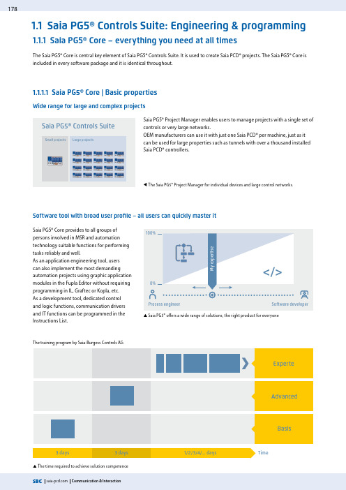
Saia PG5® Controls Suite178Wide range for large and complex projectsSaia PG5® Project Manager enables users to manage projects with a single set ofcontrols or very large networks.OEM manufacturers can use it with just one Saia PCD® per machine, just as itcan be used for large properties such as tunnels with over a thousand installedSaia PCD® controllers.Saia PG5® Core provides to all groups ofpersons involved in MSR and automationtechnology suitable functions for performingtasks reliably and well.As an application engineering tool, userscan also implement the most demandingautomation projects using graphic applicationmodules in the Fupla Editor without requiringprogramming in IL, Graftec or Kopla, etc.As a development tool, dedicated controland logic functions, communication driversand IT functions can be programmed in theInstructions List.S Saia PG5® offers a wide range of solutions, the right product for everyone1.1 Saia PG5® Controls Suite: Engineering & programming1.1.1 Saia PG5® Core – everything you need at all times1.1.1.1 Saia PG5® Core | Basic propertiesW T he Saia PG5® Project Manager for individual devices and large control networks.S The time required to achieve solution competenceSoftware tool with broad user profile – all users can quickly master itThe Saia PG5® Core is central key element of Saia PG5® Controls Suite. It is used to create Saia PCD® projects. The Saia PG5® Core isincluded in every software package and it is identical throughout.Large projectsSmall projectsProcess engineerThe training program by Saia-Burgess Controls AGPCD3.Mx6xPCD3.M3/5PCD4PCD2PCD1PCD2.MSPCD2.M4x6xPCD1.M2PCD7.DxxxVTSF19901991199219931994199519961997199819992000200120022003200420052006200720082009201020112012201320142015201620172018201920201S B C s o f t w a r e3S B C S -W e b t e c h n o l o g y4R o o m a u t o m a t i o nS Old application programs can be used with new Saia PCD® controllers and further edited with Saia PG5® Core– A tool for all platformsLicence as a "user key"Software maintenanceWe are continually advancing our software in logical and easy-to-manage innovation steps. The following diagram shows the major version changes over the past 15 years. Patches are used to manage identified errors. Version changes are not required. New functions are first tested in beta versions before the sum of all the new functions is made official in a major new version.A moderate fee is charged for major version steps with substantial additional functions. This happens every 2 to 3 years.S Milestones in software development and maintenance1S B C s o f t w a r e2C o m m u n i c a t i o n & I n t e r a c t i o n4R o o m a u t o m a t i o nSaia PG5® Core contains the following components`Project Manager (manages complex installations of networked Saia PCD® controllers including documentation)`Network Configurator (integrated network editors for the con-figuration of devices and communications networks)`Device Configurator (configuration of hardware parameters on the controller)`Symbol Editor (manages all local, global and network symbols and symbol groups. Thanks to the automatic allocation, no fixed addressing is needed)`Programming methods (integrated programming environ-ments: Fupla [function block diagram], S-Edit [instruction list IL] and Graftec [flowchart] )`Libs (standard libraries which quickly and easily enable all the core functions of the MSR/automation technology) `Web Editor (for WebSCADA functions in each controller)182Saia PG5® Project ManagerProject TreeThe layout and structure largely correspond to Windows Explorer. The "Project Tree" window allows direct access to all Saia PCD®s used in the project and their relevant settings, program files and documents. Program organ-isation by files (containing one or more program blocks) simplifies the shared use of program files in multiple Saia PCD®s.The "Program Files" folder can consist of different data types. Therefore, it is possible to save all types of pro-gramming in one folder.Messages and Error ListError and status messages are displayed in this window along with the assembly protocol. Errors in the program code are listed here after assembly, and can be located directly by clicking.Window of Saia PG5® Project ManagerNetwork ConfigurationNetwork configuration is used for the con-figuration of devices and communications networks. There are three different basic configurations:The configurations and applications are created, changed and managed in Saia PG5® Project Manager. Saia PG5® Project Manager is pivotal for all tasks with Saia PCD® controllers.The following window appears on the left edge of the screen as soon as Saia PG5® Project Manager is opened. With desktop dock-ing, there is still enough space on the right of the screen for additional windows.1. Ethernet RIO Network Configurator `Smart RIO – PCD3.T665 and PCD3.T666.2. BACnet Network Configurator `BACnet Configuration Files (*.bnt)3. S-Net Network Configurator `Profibus DP Network File (*.dp) `Profi S-IO Network File (*.sio) `LONNetwork File (*.lon)1S B C s o f t w a r e2C o m m u n i c a t i o n & I n t e r a c t i o n4R o o m a u t o m a t i o nAll parameters and modules can be viewed at a glance and printed out as system documentation in the Device ConfiguratorSymbol EditorThe Symbol Editor is the heart of Saia PG5® Core. It defines and documents all the symbols used by the program.T he various editors are connected with the Symbol Editor. New symbols used in the program code are incorporated directly by the Symbol Editor.` T he import/export function allows the reuse of pre-defined I/O lists in electrical diagrams and visualisation tools. ` S ymbols can be grouped together. All the symbols re-quired for a function form one group. This makes it easier to use functions and recognise symbols in the program code, and also gives a clearer overview in the Symbol Editor.Overview of all symbols used in the Symbol Editor184Saia PG5® Fupla (function block diagram)Fupla is the SBC proprietary function block diagram editor. It differs in many respects from other graphic programming interfaces:`One Fupla file may contain several program blocks. This means that one file can encompass an entire machine func-tion. In symbolic programming, each program block is given an individual symbol name. This prevents collisions during the build.`Fupla blocks are organised into pages. Each page can pro-duce several outputs so that entire functions can be viewed at a glance on one page.`Graphic functions (FBoxes) not only have inputs and out-puts, but also parameter windows for configuration and online modification.Saia PG5® Fupla (function block diagram)Comment:The Kopla Editor (contact plan) is an integral part of Saia PG5® Fupla Editor. Unlike conventional graphic programming environ-ments, FBoxes and contact plan elements can be combined in a single graphic.Saia PG5® S-Edit (instruction list IL)Saia PG5® S-Edit (instruction list IL)The editor for the strong instruction set of Saia PCD®. S-Edit combines an editor and online debugger in one interface. `The colour syntax function detects valid instructions and applies a colour to them. The program code is thus much easier to read and typographic errors are detected immedi-ately.`The "Bookmarks", "Goto Line", "Find and Replace" editor functions make it easier to navigate through extensive programs.`The code built can be displayed directly in the original code. The function is also used by the integrated debugger. `Complete functions can be copied from a library using drag & drop.Saia PG5® Graftec (sequential function chart)Saia PG5® Graftec (sequential function chart)Graftec (sequential function chart) is particularly suited to sequential processes. Sequential blocks are a fixed component of the PCD firmware and are processed by it efficiently.`Steps and transitions can be programmed in IL and graphi-cally in Fupla. ` T o also ensure a good overview with extensive sequential processes, division into sub-pages is possible.`In online mode, the active transition is permanently dis-played.`Option to process the code step-by-step in step mode.Programming methods in the Saia PG5® Core1851S B C s o f t w a r e3S B C S -W e b t e c h n o l o g y2C o m m u n i c a t i o n & I n t e r a c t i o n4R o o m a u t o m a t i o nStructure of the Fupla EditorThe Saia PG5® Fupla Editor is the quickest and most reliable method of implementing applications. This editor can also be easily used by those with no software programming experience. It is the right tool for optimising and modifying systems. All complex functions have been implemented by specialists in Saia PG5® S-Edit or Saia PG5® Graftec and packaged into graphic function blocks (FBoxes)."Ready and simple to use" also by service technicians and process engineers. > 95% of all applications can be implemented in the automation infrastructure through engineering using Saia PG5® Fupla alone. No line of code is written here.`Programming is facilitated with pre-programmed function blocks (FBoxes) for all standard functions`Creation of complex user programs by simply positioning and linking FBoxes without requiring extensive program-ming knowledge.`Extensive and high-performance FBox families for communi-cation and building automation tasksFeatures of the libraries`The clearly arranged tree structure simplifies FBox selection. `Parameters are conveniently entered via adjust windows in the Fupla editor, without losing the program overview`Detailed context-sensitive FBox information, clear parameter descriptions and graphic presentation in the function block diagram editor (Fupla) make user programs easy to read and understand`Online display of process values and parameter adjustment makes commissioning considerably easier and saves mainte-nance costs`Obvious differentiation between data types by using different coloursProcessusedBenefits of using the Fupla EditorSaia PG5® FuplaEach data type is identified by a colour. This makes programs easier to read.Binary data Purple Integer dataBlue Floating point dataYellow Texts (TX) and data blocks (DB)Green186Clear grouping into familiesAll FBoxes (function boxes) are grouped into families. This provides a better overview and makes it easier to find individual FBoxes.A distinction is also made between standard, application and user FBox:Standard: Shows the FBox libraries of the basic application componentsApplication: Shows the FBox libraries of the engineering application componentsUser: Only shows the FBox libraries which the user himself has createdAll: Shows all available FBox librariesF avourites: On this page the user can group together the most frequently used FBoxes (from all libraries).This means that it is no longer necessary to search for FBoxes or to switch between library tabs.FBoxes in the Saia PG5® CoreThe standard and application FBoxes are readily available for users in the Saia PG5® Core.The standard FBox libraries are basic families which offer normal logical and arithmetic operations and numerous useful systemfunctions.In addition to the standard FBoxes, the Saia PG5® Core contains additional FBoxes. These include application FBox libraries which comprise engineering families.The search function (Filter) in the Selector enables a specific FBox to be found quickly.So that Engineering can access the correct FBoxes, their function and parameters must be known. The online user manual integrat-ed into the PG5 Core is the ideal way to get a quick overview of the relevant FBoxes.Clicking on the FBox makes information such as a brief description of the FBox, an explanation of inputs and outputs, information on the parameter settings and a function description of the FBox accessible to all.HVAC online user manual1871SBCsoftware3SBCS-Webtechnology2Communication&Interaction4Roomautomation Web Editor – a powerful software toolThe production of web-based visualisation and controlinterfaces is an essential element of the engineeringeffort. Appealing, functionally designed web pages arethe public face of the system, supporting operationalefficiency and safety. A powerful tool for generating theweb pages is therefore crucial.Saia PG5® Web Editor: simple, intuitive and efficientDesigning dynamic web pages with a normal HTML editor is laborious and requires specific expertise (in-depth HTML and Javaprogramming knowledge). With the Saia PG5® Web Editor, SBC provides the user with an easy-to-use software tool for generatingweb pages to ensure that this innovative technology does not remain the preserve of a small number of specialists. The Web Editoris used to create web pages in HTML5 or in TEQ-format simply and efficiently by placing and parameterising objects. Operation ofthe editor is intuitive, and rquires no HTML or Java programming knowledge. With optimum integration into the Saia PG5® ControlsSuite and the associated direct access to all symbols, powerful macro management to generate your own reusable macros andmany other useful functions for efficient generation of web pages, the engineering costs are significantly reduced compared toother editors.The tool is designed for the automation environment. Applications include system visualisations, alarming and trending functions,or just one service page. The full integration into the Saia PG5® Core combined with Saia PCD® controllers guarantees a particularlyefficient working method.The Saia PG5® Web Editor produces appealing web visualisations with no web designer skills required.Start screen for Saia PG5® Web Editor 8The Web Editor includes a transparent and adjustable workspace for efficient operation. The workspace essentially comprises themenu/command bar, the View Editor (drawing area) and windows. With docking window technology, the user can position andshow/hide the windows as required.。
Amadeus5简单操作说明

Amadeus 5 的使用概述. 安装插入CD 并按界面提示进行。
设置在Windows的“开始”菜单里找到Amadeus 5,或点击桌面相应的图标,都可以启动AMADEUS5。
在开始菜单的界面里有以下几条信息:➢键入用户名➢Press “Tab” -按“Tab”-- 如果按“enter”键将出现一个错误信息。
➢键入用户的名称➢点击OK 键完成显示程序的主要菜单提示&建议用户名和密码默认值:姓名为“dds”,密码为“dds”注意字母的大小写“姓名”和“密码”要注意大小写。
计算机认为AFI, afi, 和 aFi 是不同的。
延时介绍如果在预制的延时时间里没有键入姓名和密码,会关闭开始窗口。
首次使用软件建议在首次使用软件时修改姓名和密码。
退出系统停止操作退出系统时,按下面步骤选择退出系统的方式:➢点击导向条最右边的标着门的图标。
➢点击界面左上角标着魔杖的图标➢点击界面右上角的“X”➢直接按功能键‘’F4’’新建数据登记项输入新的数据:➢选择需要的界面➢在工具条里点击“新建”图标,开始输入新数据➢在“名称”栏里输入新数据名称➢在“描述”栏里对输入的新数据进行说明➢填写其他信息栏➢点击工具条里的“存储”图标产生新数据,或按功能键‘’F3’’。
➢点击“关闭”图标完成输入并回到主界面,或按功能键‘’F2’’。
提示&建议Emptying fields腾空信息栏按“新建”图标,清除所有信息栏或将它们设为默认值,然后开始输入新数据。
选自我解释名称Modifying Data Entry 修改数据登记项修改一个现有的登记项:➢选择界面➢修改信息栏➢点击工具条里的“存储”图标产生新数据➢点击“关闭”图标完成输入并回到主界面Chose self-explanatory names 选自我解释名称演示版本和加密狗可以运行AMADEUS5的演示版。
演示版里包括提及到的报警、图形、电梯管理和时间管理等所有功能。
altanium matrix5 用户指南说明书
Altanium Matrix5用户指南原始说明发行:v 1.0 — 2020 年 2 月本产品手册的目的是提供有关安全操作和/或维护的信息。
Husky 保留对产品进行更改的权利,以便不断改进产品功能和/或性能。
这些更改可能导致不同和/或额外的安全措施,在进行更改时,将通过公告向客户传达这些措施。
本文包含的信息是 Husky Injection Molding Systems Limited 的专有财产。
除合同明确授予的任何权利外,未经 Husky Injection Molding Systems Limited 事先书面许可,不得对本文全部或部分内容进行进一步发布或商业使用。
尽管有上述规定,但 Husky Injection Molding Systems Limited 仍允许其客户仅出于有限内部使用的目的而复制本文。
这些资料中引用的 Husky® 产品或服务名称或徽标是 Husky Injection Molding SystemsLimited 的商标,其某些附属公司可在许可下使用它们。
所有第三方商标均为各自第三方的财产,可能受适用版权、商标或其他知识产权法和条约的保护。
每个此类第三方均明确保留对此类知识产权的所有权利。
© 2019 Husky Injection Molding Systems。
保留所有权利。
iiiii一般信息电话支持号码有关现场服务,请联系最近的 Husky 地区服务和销售办事处。
有关非紧急问题,请向 Husky 发送电子邮件,电子邮件地址为 ********************。
Husky 地区服务和销售办事处有关最近位置,请访问 www.husky.co 。
产品升级可获得升级,升级可改善输出,缩短周期时间,以及为 Husky 设备增加功能。
要查看可获得哪些升级,请访问 www.husky.co ,或者致电最近的 Husky 地区服务和销售办事处。
дивизиvalue mars 5igue波器说明书

SpecificationSNormal Operating Voltage: 15 to 32 VDC Maximum Current Draw: 5.0 mA (LED on)Average Operating Current: 375µA (group poll), 350 µA (direct poll), 600 µAmps (communication, IDC shorted)EOL Resistance:47K Ohms Max. IDC wiring resistance: 1,500 Ohms Maximum IDC Voltage: 11 Volts Maximum IDC Current: 450µAT emperature Range: 32°F to 120°F (0°C to 49°C)Humidity: 10% to 93% Non-condensingDimensions: 41⁄2˝ H x 4˝ W x 11⁄4˝ D (Mounts to a 4˝ square by 21⁄8˝ deep box.)Accessories:SMB500 Electrical BoxBefore inStallingThis information is included as a quick reference installation guide. Refer to the control panel installation manual for detailed system information. If the modules will be installed in an existing operational system, inform the opera-tor and local authority that the system will be temporarily out of service. Dis-connect power to the control panel before installing the modules.NOTICE: This manual should be left with the owner/user of this equipment.general DeScriptionThe SK-Monitor Module is intended for use in intelligent, two-wire systems, where the individual address of each module is selected using the built-in rotary switches. It provides either a Class A or Class B fault tolerant initiating device circuit (IDC) for normally open contact fire alarm and supervisory de-vices, or either normally open or normally closed security devices. The mod-ule has a panel controlled LED indicator.compatiBility requirementST o ensure proper operation, this module shall be connected to a compatible Silent Knight system control panel (list available from Silent Knight).figure 1. controlS anD inDicatorS:C1067-00mountingThe SK-Monitor mounts directly to 4-inch square electrical boxes (see Figure 2). The box must have a minimum depth of 21⁄8 inches. Surface mounted elec-trical boxes (SMB500) are available from Silent Knight.inStallation anD maintenance inStructionSSK-460-0131I56-3442-000SK-monitor modulefigure 2. moDule mounting:NOTE: For UL Listed security installations, the SK-Monitor must be mountedwithin the control panel enclosure.C1066-00WiringNOTE: All wiring must conform to applicable local codes, ordinances, and regulations. This module is intended for power limited wiring only.1. Install module wiring in accordance with the job drawings and appropri-ate wiring diagrams.2. Set the address on the module per job drawings.3.S ecure module to electrical box (supplied by installer), as shown in Figure 2.I56-3442-0007550 Meridian Circle, Maple Grove, MN 55369-4927763-493-6455; 800-328-0103 Fax: 763-493-6475figure 3. typical 2-Wire initiating circuit configuration, nfpa Style B or Security SyStemS:NOTE: For UL Listed security installations, the SK-Monitor must be mounted within the control panel enclosure.FROM PANEL OR PREVIOUS DEVICE47K EOL RESISTOR ELR-47KALL WIRING SHOWN IS SUPERVISED AND POWER LIMITEDPOWER LIMITED: 450µA MAX. @ 11 VDC MAX INSTALL CONTACT CLOSURE DEVICES PERMANUFACTURER’S INSTALLATION INSTRUCTIONS.C0918-00figure 4. typical 4-Wire fault tolerant initiating circuit configuration, nfpa Style D:FROM PANEL OR PREVIOUS DEVICEALL WIRING SHOWN IS SUPERVISED AND POWER LIMITEDINSTALL CONTACT CLOSURE DEVICES PER MANUFACTURER’S INSTALLATION INSTRUCTIONS.INTERNAL AT TERMINALS 8 & 9C0919-00SK-460-013 2 I56-3442-000 ©2009 Silent Knight。
- 1、下载文档前请自行甄别文档内容的完整性,平台不提供额外的编辑、内容补充、找答案等附加服务。
- 2、"仅部分预览"的文档,不可在线预览部分如存在完整性等问题,可反馈申请退款(可完整预览的文档不适用该条件!)。
- 3、如文档侵犯您的权益,请联系客服反馈,我们会尽快为您处理(人工客服工作时间:9:00-18:30)。
AMADEUS5
用户使用手册
2010
1软件安装
运行INSTALL.BAT,选择English,安装完成后再进行汉化,如果您要安装的是ACCESS server版进行默认安装即可,如果你要安装工作站,在安装过程中请选择Workstation(默认是Server)。
如果你要安装SQL 版,在安装过程中请选择Microsoft SQL Server(默认是Microsoft ACCESS),认证模式选择SQL Authetication,密码与您安装SQL时的相同。
安装完毕后进入登陆界面,用户名、密码均为dds,进入软件后进行汉化。
选择“Tools”-“Options”-“Language”-Chinese,其他不用修改。
软件安装完毕。
2定义软件操作人员及权限
首先定义权限,选择“参数”-“授权等级”-“新的”-填写权限的“名称”-选择权限(V读、写和删除,表示操作员可对这部分菜单进行操作;X没有进入认可,在软件中不显示该部分菜单;R只能读,不能修改,软件显示该部分菜单,但操作员没有进行操作的权限)-“保存”
权限定义完毕
之后定义使用者,选择“参数”-“使用者”-“新的”-填写“名称”-填写“密码”-选择定义好的“授权等级”-“保存”
使用者定义完毕
3定义通行等级:该功能决定“谁,何时能进入何地”
定义权限,选择“参数”-“通行等级”-“新的”-填写“名称”-选择权限(V表示允许进入的门;X表示不能进入的门)-“保存”
4定义持卡人
新增持卡人:选择“参数”-“所有持卡人”-“新的”(1)-填写“姓”(姓名)-“存储”(2)-选择“通行等级”(3)-“新建”(4)卡-填入“编码”(卡号),其他项不作修改,如不知卡号,选“来自卡”,此时在任意读卡器读卡,卡号会读上来,选“存储“-最后再选“存储”(2)
编辑持卡人:选择“参数”-“所有持卡人”-从下拉列表里找到要修改的人-选择“编辑”(6)卡-填入新“编码”(卡号),其他项不作修改,如不知卡号,选“来自卡”,此时在任意读卡器读卡,卡号会读上来,选“存储“-最后再选“存储”(2)
删除持卡人:选择“参数”-“所有持卡人”-找到要删除的人点“删除”(5)-进入“工具”-“创建卡组”-“删除”-分别点击“清除所有未分配的卡片”“清楚所有已经删除的持卡者”
完成
5记录的查询
选择工具条中的“显示记录”-在弹出的窗口中选“创建新记录”-选择要看的记录类型-进行条件的筛选-结束即可
输出报表:选择“输出”-选择“输出格式”-指定“文件名”-OK即可
6数据库的维护
当对软件设置,控制器参数,人员进行改动时建议执行“保存数据库”;
记录数据库的大小与软件的运行速度相关,建议定期将记录到处即执行“存储记录”;
恢复记录时选择否:将原有的记录追加到现有的记录里,如选是:将现有的记录替换成恢复的记录。
7更改控制器名称,读卡器名称,门磁状态名称等参数
选择“参数”-“控制器”-在“常规”里“名称”可更改控制器名称,选择“读卡器”-选。
在读卡器窗口的“常规”中更改读卡器名称。
8查看地图
选择“事件处理”-“启动报警”-选择要查看的地图;
选择“输出状态”—右键选择“常开”可将门打开,恢复选“常态”。