SCR3200系列恒功率中频电源控制板中英文说明
恒功率中频电源使用说明书

IC3A构成阻抗调节器,它与电流调节器是并列的关系,用于控制逆变桥的引前角。其作用可间接地使恒功率中频电源达到恒功率输出,或者可提高整流桥的运行功率因数。微动开关DIP-2可关掉此调节器。
IC4C构成逆变角调节器,然后由IC4D反相输出。
KGPS-7503φ-380V1200A750V750KW0.5%
KGPS-10003φ-660V920A1200V1000KW0.5%
KGPS-15003φ-660V1380A1200V1500KW0.5%
由CON2-1和CON2-2输入的中频电压信号,经IC1AD转换成方波信号,输入到IC6的30脚。由IC6的15P、16P输出的逆变触发信号,经IC7A隔离放大后,驱动逆变触发MOS晶体管Q5、Q6。IC6B构成逆变压控时钟,输入到IC6的33脚CLOK2;同时又进行频压转换后用于驱动频率表。W6微调电位器用于设定压控时钟的最高频率(即逆变它激信号的最高频率),W5微调电位器用于整定外接频率表的读数。
恒功率中频电源使用说明书
感谢您选用宏润电炉厂最新改进版的KGPS系列恒功率中频电源。为了更好地使用和维护本装置,请在使用前仔细阅读本说明书。
一. 概述
1.
电压PI调节器由IC3B组成,其输出信号由DW1及Q1进行钳位限幅。IC4B和IC5C组成电压闭环自动投入电路。由IC3D构成电流PI调节器,然后由IC4A隔离,控制触发电路的压控时钟。
中频电源使用说明书

中频电源使用说明书SHI YONG SHUO MING SHU目录一、概述二、型号说明三、安装配线四、操作运行五、参数功能解释六、常见故障及检修七、保养与维护八、品质保证一、概述感谢您选用我司的中频系列数字开关电源。
此电源是采用高频软开关技术生产制造的一种高效率交-直-交电源变换装置,不仅物美价廉,安全可靠,而且性能优越、省时省电,是取代以往任何开关电源的理想装置,具有广泛的适用性和新优势:1、体积小、重量轻。
本产品采用高频双极性PWM单相逆变技术、优质铝型材散热器,与以往串联谐振中频电源相比,体积小,重量轻、价格便宜。
2、性能稳定、质量可靠。
本产品采用单片机控制、硬件使用变频器结构,设计精巧、科学合理,电子器件均选用进口元件,各项指标均优异于可控硅逆变电源,在性能和质量上既稳定又可靠。
3、节能省电。
本公司所生产的高频电源,工作效率均在98%以上,与普通谐振电源的工作效率相比,节电率可达20%,有效地降低生产成本。
基于上述优点,高频数字电源现已快速、无可比拟的优势,广泛地使用在电镀、电解、氧化、着色、电泳、加热等多种场合、并将有取代其它类型电源的发展趋势。
我司是一家致力于电源变换的高新科技公司,其产品已应用于能源、冶金、石油、化工、建材、注塑、纺织、电镀、民用等众多场合。
二、型号说明:1、铭牌:2、型号说明:HS –MF –075三、安装配线:2.1 外型尺寸与安装尺寸(详见附录)2.2 安装现场:·室内通风良好。
·环境温度-10℃~ +40℃。
·尽量避免高温多湿,湿度小于90%,无雨水滴淋。
·无易燃、易爆、腐蚀性气体和液体。
·无电磁干扰,远离干扰源。
·海拔1000米以下,当海拔高时,应每100米减小5%定值。
2.3 配线:2.3.1控制回路端子排的排列:2.3.2主回路端子排列:R S T G P N U V W 2.3.3主回路端子说明:·电源输入:R 、S、T ;直流母线电压:P、N ·中频输出: U、W2.4.1控制回路接线:为了减小控制信号的干扰和衰减,控制信号的连线应限制在50m以内,并与动力线的间隔距离要大于30cm,连接模拟输入,输出信号时,请使用双绞屏蔽线。
中频控制板说明书
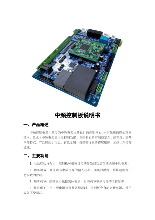
中频控制板说明书一、产品概述中频控制板是一款专为中频电源设备设计的控制核心,采用先进的微处理器技术,集成了中频电源的主要控制功能。
该控制板具有高稳定性、高精度、高效率等特点,广泛应用于冶金、有色金属、陶瓷等行业的感应熔炼、加热、焊接等领域。
二、主要功能1. 电源启动与关闭:控制板可根据设定的参数自动启动或关闭中频电源。
2. 功率调节:通过调节中频电源的输入功率,实现对温度、熔炼速度等工艺参数的控制。
3. 频率调节:控制板可根据实际需求,自动调节中频电源的工作频率。
4. 异常保护:当中频电源出现异常情况时,控制板会自动切断电源,保护设备不受损坏。
5. 数据记录与显示:控制板可实时记录中频电源的工作状态,并通过显示屏显示各项参数。
三、使用方法1. 连接电源:将220V交流电接入控制板的电源接口,确保电源线连接牢固。
2. 启动电源:按下控制板的电源开关,中频电源开始工作。
3. 调节功率与频率:根据实际需求,使用控制板上的旋钮或键盘输入相应的参数。
4. 观察状态:通过显示屏观察中频电源的工作状态,确保各项参数正常。
5. 关闭电源:工作完成后,按下控制板的关机按钮,中频电源将自动关闭。
四、注意事项1. 使用前请仔细阅读说明书,确保正确操作。
2. 控制板应安装在通风良好的环境中,避免潮湿、高温和灰尘。
3. 定期检查控制板的连接线是否牢固,如有松动应及时紧固。
4. 不要随意拆卸或改装控制板,以免造成损坏或安全事故。
5. 如发现控制板有异常情况,应立即停止使用,并及时联系专业人员进行检修。
五、维护与保养1. 定期清洁控制板的表面,保持清洁干燥。
2. 定期检查控制板的连接线是否老化或破损,如有需要应及时更换。
3. 控制板的使用寿命取决于工作环境和使用频率,如发现性能下降应及时更换。
4. 在进行维护和保养时,应遵循相关安全规范,确保操作人员的安全。
以上是中频控制板的详细说明书,包括产品概述、主要功能、使用方法、注意事项和维护与保养等方面的内容。
E系列 scr电力控制器使用说明书

第一章SCR电力控制器总述前言SCR电力控制器(SCR POWER CONTROLLER),目前在工业中已被广泛应用于各种电力设备中,诸如窑炉、热处理炉、电气高温炉、高周波机械、电镀设备、印染设备、涂装设备、射出机、押出机等等,然而因为负载的不同,使用环境的限制,而又有各种不同的控制模式及各种追加配备,如相位控制(Phase Angle Control),分配式零位控制(Distributed Zero Crossover),时间比例零位控制(Time Proportional Zero Crossover)。
基于此,本公司研制了P/E系列各种不同控制模式之电力控制器,以满足各用户的需要。
P/E系列SCR电力控制器,完全采用SCR POWER MODULE密封的IC化电路板,使整个控制器简单轻便,以提高控制器的可靠度,当要使用本控制器时,请详读本说明,以了解各种控制器的结构、功能、接线方法。
SCR电力控制器有多种不同的叫法:如晶闸管电力控制器,可控硅电力调节器,可控硅电力调功器,功率控制器等,虽然叫法不同,但所指的都是同一种产品。
本公司以SCR电力控制器来命名。
1,原理简介SCR电力控制器的基本原理是通过控制信号输入,去控制串在主回路中的SCR(晶闸管)模块,改变主回路中电压的导通与关断,由此达到调节电压或功率的目的。
控制器一般是由控制板加上主机(主回路)组成。
SCR电力控制器又可分为调压器和调功器。
采用相位控制模式的SCR电力控制器可叫做调压器,它可以方便地调节电压有效值,可用于电炉温度控制,灯光调节,异步电动机降压软启动和调压调速等,也可用做调节变压器一次侧电压,代替效率低下的调压变压器。
采用零位控制模式的SCR电力调节器可叫做调功器,也叫周波控制器。
它对交流电压的周波进行控制,通过控制负载电压的周波通断比来控制负载的功率,多用于大惯性的加热器负载。
采用这种控制,即实现了温度控制,又消除了相位控制时带来的高次谐波污染电网,不过控制精度有所降低。
SCR19系列电源控制器产品说明书
=
5%
power
change
minimum step change. Infinitely
variable time base units also
produce less power line disturbances.
Dimensions: mm (in)
Model No.
ߜ No Relay Noise—Contact Arc Noise Eliminated
ߜ Semiconductor I2T Fusing ߜ Optically Isolated Control
Signal Input
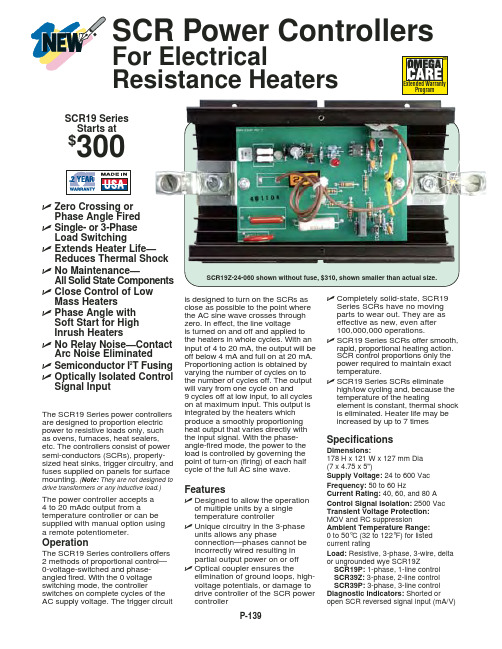
The SCR19 Series power controllers are designed to proportion electric power to resistive loads only, such as ovens, furnaces, heat sealers, etc. The controllers consist of power semi-conductors (SCRs), properlysized heat sinks, trigger circuitry, and fuses supplied on panels for surface mounting. (Note: They are not designed to
controller with infinitely variable time
base provides maximum closeness
in temperature regulation by offering
higher power resolution than fixed
常见的液晶电视机电源板、电源开启、背光开启、亮度控制英文符号

常见的液晶电视机电源板、电源开启、背光开启、亮度控制英
文符号
液晶电视机、液晶显示器、一般机器里面有几块板子的时候,都是通过插排线连接的,那么知道这些插排线引脚的定义,对我们分析液晶电视机线路,维修有很大帮助。
先看几张图片:
一般插座上标注的GND、12V、5V这些都很好理解,但是标注的电源开启信号、背光开启信号、亮度控制信号就有很多种标识了,下面我找资料总结了一下各种标注符号:
电源开关机控制:STB、PO-ON、OFF/ON、P-ON、STANDBY 等
背光开启控制:SW、EN、ENA、LCD-ON/OFF、BL-ON/OFF、BKLT-EN等
亮度调节:ADJ、DIM、BRI、PWM、IPWN、BL-DIM、BKLD-ADJ
BRIGHTNESS 等
电子元器件、基础电路视频教程。
SV-3200中控用户手册

多媒体中央控制系统(SV-3200)安装使用手册SV-3200中控系统安装使用手册2003 [09]目录一、产品简介 (4)二、设备包装说明 (5)三、主控机前面板示意图 (5)四、主控机后面板示意图 (6)五、系统主机、操作面板、电脑的连接 (6)六、应用设备连接示意图 (6)七、红外发射棒的连接 (7)八、投影机控制线连接: (7)九、电动屏幕接线图 (7)十、操作面板使用说明 (8)1、43键面板 (8)十一、多媒体控制软件的安装 (10)十二、红外控制器的使用 (11)十三、设备红外遥控器代码的学习和录入 (11)十四、主控机系统各项参数 (12)十五、常见故障排除 (14)1、通过面板“系统开”无法开机 (14)2、面板控制不灵 (14)3、有些设备红外遥控不灵 (14)4、电脑软件无法控制 (14)5、红外学习不成功或显示成功却不能遥控 (15)十六、本手册说明 (15)前言感谢您购买和使用本公司的产品,在使用本机前请细阅这本用户手册以便能正确使用并且请妥善保存这本手册万一有不了解或故障时这本手册会带给您很大的帮助。
可编程多媒体中央控制系统是最新开发的智能化产品,是通过面板控制及计算机软件控制的电教产品。
该系统的所具有的特点:控制主机是SV-3200(SVS)电教产品的经典之作,一体化的控制结构、全双向控制方式、美观的控制面板,同时支持状态反馈,一目了然。
它集成了3路电源管理、4选2路视/音频切换矩阵、4路红外遥控、红外遥控自学习、3X2VGA信号切换、全数码声音控制、可编程串行通讯等功能模块。
其强大的红外学习功能对所有红外码都能有效学习,遥控灵敏;其灵活的开关机编程功能使得使用非常灵活方便。
它有较强的接入兼容性,可通过按键控制面板进行控制,也可以通过软件控制,还可以连接AMX、快思聪等设备。
为确保设备可靠使用及人员的安全,请在安装、使用和维护时,请遵守以下事项:1、为确保操作安全,应确保电源线接地良好,务必将随机提供的三相插头插入地线有效的标准三脚电源插座,确保设备的输入电源为220V50HZ的交流电。
3200系列温控器说明书
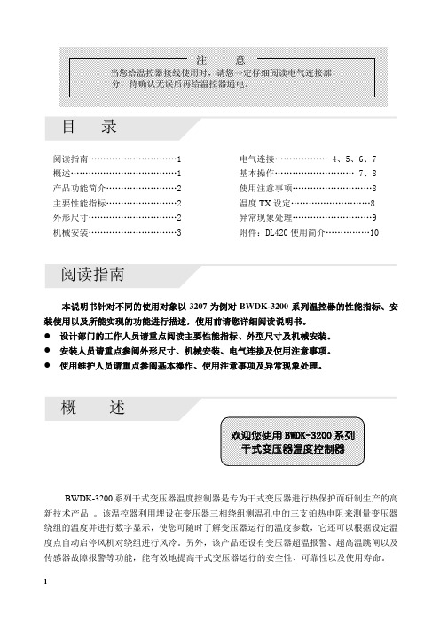
目录阅读指南…………………………1 电气连接……………… 4、5、6、7概述………………………………1 基本操作……………………… 7、8产品功能简介........................2 使用注意事项 (8)主要性能指标........................2 温度TX设定 (8)外形尺寸..............................2 异常现象处理 (9)机械安装..............................3 附件:DL420使用简介 (10)阅读指南本说明书针对不同的使用对象以3207为例对BWDK-3200系列温控器的性能指标、安装使用以及所能实现的功能进行描述,使用前请您详细阅读说明书。
●设计部门的工作人员请重点阅读主要性能指标、外型尺寸及机械安装。
●安装人员请重点参阅外形尺寸、机械安装、电气连接及使用注意事项。
●使用维护人员请重点参阅基本操作、使用注意事项及异常现象处理。
BWDK-3200系列干式变压器温度控制器是专为干式变压器进行热保护而研制生产的高新技术产品。
该温控器利用埋设在变压器三相绕组测温孔中的三支铂热电阻来测量变压器绕组的温度并进行数字显示,使您可随时了解变压器运行的温度参数,它还可以根据设定温度点自动启停风机对绕组进行风冷。
另外,该产品还设有变压器超温报警、超高温跳闸以及传感器故障报警等功能,能有效地提高干式变压器运行的安全性、可靠性以及使用寿命。
12产品功能简介主要性能指标正常工作环境温度:-10~+55℃ 控制误差:<±1℃相对湿度:5%~95% 显示方式:1位相位显示,3位半温度值显示 工作电源:AC220V ±10%,0.5A ,50Hz 外形尺寸(体积):263mm ×196mm ×85mm 测温范围:0~199.9℃ 最大功耗:10W测温精度:±0.5% 总重量:2.4kg外形尺寸前视图侧视图后视图3机械安装安装方式一:变压器本体安装安装方式二:变压器外壳安装图a 建议用安装支架结构图图b 安装后示意图图a 建议变压器外壳开孔尺寸图图b 安装示意图图c 安装后的位置图A.温控器铂电阻传感器的连接CA型铂电阻传感器电气连接图CB型铂电阻传感器电气连接图:B相B相45B .传感器的安装:安装步骤:1234传感器安装示意图C. 温控器端子排定义及接线1、3205端子排端子定义14 13 12 11 10 9 8注:1.1、2、3、4号端子空闲不用。
洛阳海特 KGPS中频电源装置 SCR系列控制板 使用说明
2)适用频率范围 400Hz-8000Hz
3)起动方式
零电压软起动
4 ) 起 动 成 功 率 :轻 载 不 小 于 1 0 0 % ,重 载 不 小 于 9 5 %
5)调整方式
电流、电压双闭环调节
6)整流触发脉冲移相范围
0-150°
7)整流触发脉冲形式及脉宽 双窄脉冲列18°
8)整流触发脉冲最大触发电流 大于800mA
我公司生产的SCR系列中频电源控制板具有以下优点: 1. 控制 板 采用 了 先进 的集 成 电路 作 为控 制系 统 的核 心 ,控 制能 力 极强 ,集
成度 高 ,整个 控 制 电路 安 装在 一 块 280*220mm 左 右的 印 刷 电路 板 上 ,与 主电路的连线只用四五十条,简单而且可靠,却具有强大的控制功能。 2. 控制板采用三相电源同步直接输入,省去了体积较大的同步变压器等, 使整机电路进一步简化,设备体积减少,安装调试简单而且维修方便, 控制系统如有故障,只要将备用板换上即可,省时省力,不影响生产。 3. 该 控 制 板 采 用 内 置 固 态 继 电 器 代 替 了 外 设 的 中 间 继 电 器 ,进 行 起 动 和 停 止的控制,不仅节省了成本与设备体积,而且使连线变得更加简单。 4. 该控制板具有完善的过流、过压、限流、限压等多路保护系统,一旦电 路出 现 故障 ,保 护 系统 能 在短 时 间内 动作,可 靠地 保 护 晶闸 管 和中 频电 容 等 贵 重 元 件 ,以 免 损 坏 ,造 成 不 必 要 的 损 失 。该 控 制 板 还 具 有 保 护 动 作 后 ,功 率 调 节 电 位 器 反 时 针 旋 到 底 时 ,保 护 系 统 自 动 复 位 ,有 效 地 防 止 了 误 操 作 且 在 大 功 率 状 态 下 电 源 系 统 快 速 启 动 ,有 大 的 冲 击 而 造 成 元 器件的损坏。 5. 该 控 制 系 统 采 用 零 电 压 软 起 动 和 慢 起 动 的 功 能 ,并 采 用 了 先 进 的 双 闭 环 调 节 系 统 ,在 实 际 使 用 中 能 100%可 靠 起 动 ,并 且 起 动 无 冲 击 。设 备 在 实 际运行中,负载变化较大的情况下,也能够稳定可靠地工作。 6. 该 控 制 系 统 调 整 点 少 ,控 制 板 安 装 好 后 ,用 户 只 需 将 过 流 、过 压 、限 流 、 限压调整好即可。 7. 该控制板控制的电源设备对各种负载的适应性强,可广泛应用于煅造、 冶炼、精密铸造、热处理、焊接、弯管等工业领域。 我公司生产的IGBT高频电源控制板除具有SCR系列中频电源控制板 类似优点外,还设有水压.温度等保护,设备频率范围可从3KHz-50K
3200系列_中文手册
31ID 调节器 使用手册
目录
1.
1.1 1.2 1.3 1.4 1.4.1 1.4.2 1.4.3 1.4.4 1.5
2.
2.1 2.2 2.3 2.4 2.5 2.6 2.7 2.8 2.9 2.10 2.11 2.12 2.13 2.14
操作等级 2.............................................................................. 16
进入等级 2..........................................................................................................16 返回到等级 1 ..................................................................................................16
变频器中英文液晶显示对照表

变频器中英文液晶显示对照表变频器中英文液晶显示对照表设定状态代码中文英文F1.00 参考输入 FREQ REFF1.01 启/停控制 CONT METHOD F1.02 输入方式 INPUT SELF1.03 键盘/计算机 K/C SETTING F1.04 模拟增益K1 GAIN K1 F1.05 模拟增益K2 GAIN K2F1.06 加速时间1 ACC TIME 1F1.07 减速时间1 DEC TIME1F1.08 加速时间2 ACC TIME2F1.09 减速时间2 DEC TIME2F1.10 加速时间3 ACC TIME3F1.11 减速时间3 DEC TIME3F1.12 加速时间4 ACC TIME4F1.13 减速时间4 DEC TIME4F1.14 转矩提升 TORQV BOOST F1.15 载波频率 CARRY FREQ F1.16 噪声自调整 YAWP TUNEF1.17 输出电压 OUTPUT VOLF1.18 滑差补偿增益 SLIP GAINF1.19 滑差补偿滤波 FILTER TIME F1.20 最大频率 MAX FREQF1.21 电机额定频率MOTO RTD FRQ F1.22 上限频率HIGH LIMITER F1.23 下限频率 LOW LIMITER F1.24 多段速度1 MULTI HZ 1 F1.25 多段速度2 MULTI HZ 2F1.26 多段速度3 MULTI HZ 3F1.27 多段速度4 MULTI HZ 4F1.28 多段速度5 MULTI HZ 5F1.29 多段速度6 MULTI HZ 6F1.30 多段速度7 MULTI HZ 7F2.00 跳跃频率1 JUMP FREQ 1 F2.01 跳跃频率2 JUMP FREQ 2 F2.02 跳跃频率3 JUMP FREQ 3 F2.03 跳跃频率范围 JUMP FREQ WF2.04 加/减速模式 ACC/DEC PTN设定状态代码中文英文F2.05 反转禁止功能 REV LOCKF2.06 运行方向设定 KEB RUN SEL F2.07 停车功能 STOP FUN F2.08 电流限幅功能 C LIMIT FUN F2.09 电流限幅水平 C LIMIT LVL F2.10 热过载继电器 ELECTRN OLF2.11 自动稳压功能 AVR FUNCTION F2.12 过电压保护 V LIMIT FUN F2.13 回升过电压 P MODE SEL F2.14 启动制动电压 ST BRK LVL F2.15 启动制动时间 ST BRK TIME F2.16 直流制动频率 DC BRK FREQ F2.17 直流制动电压 DC BRK LVLF2.18 直流制动时间DC BRK TIME F2.19 自动复位次数RESET TIMES F2.20 复位间隔时间 RES INTERVAL F2.21 故障继电器 FAULT RELAY F2.22 PM0输出选择 PWM0 SELF2.23 PM1输出选择 PWM1 SELF2.24 PM0输出倍率 PWM0 COEFF F2.25 PM1输出倍率 PWM1 COEFF F2.26 机械速度系数 SPEED COEFF F2.27 频率水平检测 FDT LEVELF2.28 频率检测范围 FAR HYSTRF2.29 参数设定方式PRT SET SEL F2.30 输入端子选择X1~X5 FUNF2.31 输出端子选择 Y1~Y3 FUNF2.32 语言选择 ENG/CHNF2.33 运行监视选择 R FUNC CODE F3.00 起始电压 START VOL F3.01 中间电压1 MIDDLE VOL1 F3.02 中间电压2 MIDDLE VOL2 F3.03 终止电压 END VOLTAGE F3.04 起始频率 START FREQ F3.05 中间频率1 MIDDLE FREQ1 F3.06 中间频率2 MIDDLE FREQ2F3.07 终止频率 END FREQF3.08 偏置频率 FREQ BIASF3.09 偏置频率1 FREQ BIAS1F3.10 偏置频率2 FREQ BIAS2 F3.11 偏置频率3 FREQ BIAS3设定状态代码中文英文F3.12 模拟电压1 ANALOG VOL1F3.13 模拟电压2 ANALOG VOL2F3.14 模拟电压3 ANALOG VOL3F3.15 程序运行模式 PATTERN SELF3.16 程序定时T1 STAGE TIME1F3.17 程序定时T2 STAGE TIME2F3.18 程序定时T3 STAGE TIME3F3.19 程序定时T4 STAGE TIME4F3.20 程序定时T5 STAGE TIME5F3.21 程序定时T6 STAGE TIME6F3.22 程序定时T7 STAGE TIME7F3.23 正反加减T1 STAGE FRAD1F3.24 正反加减T2 STAGE FRAD2F3.25 正反加减T3 STAGE FRAD3F3.26 正反加减T4 STAGE FRAD4F3.27 正反加减T5 STAGE FRAD5F3.28 正反加减T6 STAGE FRAD6F3.29 正反加减T7 STAGE FRAD7F3.30 摆频加速时间 SWAP F ACC 1 F3.31 摆频减速时间 SWAP F ACC 2 F4.00 PID模式 PID MODEF4.01 PID反馈 PID F SELF4.02 变送器模式 SENSOR MODEF4.03 反馈偏置电压 F BIAS VOLF4.04 反馈滤波时间 FEED FILTERF4.05 反馈显示系数 PID G COEFFF4.06 PID输入值 K/C PID INPT F4.07 比例P增益 P GAINF4.08 积分时间常数 PID I TIMEF4.09 微分时间常数 PID D TIMEF4.10 积分作用范围 PID I LIMITF4.11 本机地址号码 ADDRESS CODE F4.12 串行波特率 BAUD RATEF4.13 串行效验方式 PARITY MODEF4.14 保留 RESERVEF5.00 电机额定功率MOTO RTD POW F5.01 电机额定电压MOTO RTD VOL F5.02 电机额定电流 MOTO RTD CUR F5.03 电机额定转速 MOTO RTD SPD F5.04 电机连线方式 MOTO C TDTY F5.05 电机参数自测 MOTO AUTOTUN设定状态代码中文英文F5.06 定子电阻 STATOR RESISF5.07 定子电感STATOR INDUCT F5.08 空载励磁电流EXCI TATION C F5.09 负偏增益K3 GAIN K3F5.10 LP屏蔽功能 SHIELD FUNCF5.11 机器使用时间 RUNNING TIME F5.12 变频器机型 MODE F5.13 变频器额定Pe RATED PEF5.14 变频器额定Ve RATED VEF5.15 变频器额定Ie RATED IEF5.16 厂家密码 PASSWORDF5.17 XXXX XXXXF5.18 XXXX XXXXF5.19 XXXX XXXXF5.20 XXXX XXXXF5.21 XXXX XXXX运行状态代码中文英文C00 输出频率 OUTPUT FREQ C01 输入频率 INPUT FREQC02 PID输入PID INPUTC03 PID反馈PID FEED BACK C04 电流标幺值 CURRENT PER C05 电流实际值 M CURRENT C06 电压标幺值 VOLTAGE PER C07 电压实际值 M VOLTAGEC08 直流母线电压 DC VOLTAGE C09 机械速度 MOTOR SPEED C10 OL计数OL LEVELC11 运行时段 STAGEC12 程序运行时间 STAGE TIME 故障状态代码中文英文无故障/正常 00短路故障 SC过热故障 OH缺相故障 LPI C故障 EC瞬时过压 HOU稳态过压 SOUE00 瞬时欠压 HLU稳态欠压 SLU瞬时过流 HOC稳态过流 SOC过载 OL手动取消 STP自由停车 SEE电阻异常 SRE电流异常 SCEE01 故障输出频率 ERR FREQE02 故障输出电流 ERR CRUUENTE03 故障直流电压 ERR DC VOLE04 故障运行方向 ERR DIRECTE05 故障运行状态 ERR STATEE06 故障保护状态 PRET STATEE07 前一次故障 FIRST ERRE08 前二次故障 SECOND ERRE09 前三次故障 THIRD ERRSINE003 系列变频器操作一般步骤操作SINE003系列通用变频器的常规步骤:l 阅读变频器说明书;l 变频器主回路、控制回路接线;l 断开负载(若要进行电机参数自辩识,不要则跳过此步骤);l 变频器上电;l 恢复出厂值(F2.29=3);l 设定电机铭牌参数F1.21,F5.00,F5.01,F5.02,F5.03,F5.04,这些参数必须设定);l 电机参数自辩识(不要则跳过此步骤);l 断电,连接负载再上电(未断开负载,跳过此步骤); l 参数设定(与设备要求匹配。
说明书(中英文)

本充电电源的电原理方框图如下示:Block diagram of electric principle of the charging power supply is as follows:
AC 输入
EMI/软开 关
全桥 整流
平滑 滤波
平滑 滤波
平滑 滤波
DC 输出
输入过压、欠 压保护
逻辑变换主控
采样 反馈
感谢您购买本公司开发生产的电源产品! Thanks for purchasing the power supply products developed and produced by us!
请您在使用本产品前详细阅读本使用说明。 Please read the instructions carefully before using the products.
QM/KST
武汉康思坦船舶电器有限公司
Wuhan Constant Ship electric appliance Co., LTD
KST-GC-09-S-V1.0
产品说明书
Product specification
型 号:SCT 系列充电电源 MODEL: SCT Series charging power supply
制 作 商:武汉康思坦船舶电器有限公司 BUSIBESS: Wuhan Constant Ship electric appliance
Co., LTD 地 址:武汉市洪山区白沙洲大道建和工业园 1 栋 3 楼
3rd Floor, No. 1 Building,JianHe Industrial Park, Baishazhou Avenue,Hongshan District ,Wuhan 联系电话:027-88152340 TEL: 027-88152340 邮 编:430064 MAIL: 430064
中秀3200安装调试说明(新1版)

2
Esc
退出当前窗口,回到上一级菜单
3
Ctrl
切换组合键,与其它键组合使用
4
Enter
确认当前操作或进入到下一级菜单
5
y
上下菜单切换,子菜单中数值增加,或与Ctrl键组合为光标上移
6
z
上下菜单切换,子菜单中数值减少,或与Ctrl键组合为光标下移
7
w
光标左移
8
x
光标右移
4、菜单操作 控制器上点后按Menu键进入主菜单,画面如下:
4、电源端子说明
插件代号 端口号 功能说明
5V+
主控制板5V工作电源+,电流2A
5V-
主控制板5V工作电源-,电流2A
FG
主控制板接地端子
24V+ 主控制板24V工作电源+,电流1A
J5 24V- 主控制板24V工作电源-,电流1A
NC
555
主控制板对外提供24V电源+,电流<1A
551
主控制板对外提供24V电源-,电流<1A
J8
COM6 COM7 T17 T18 T14 T15 T16 COM8 COM9
J9 A+ AB+ B551
J10 CAN1H CAN1L LADH LADL CARH
J11 CARL GROH GROL 485A 485B
3/85
MF5000系统调试手册
GWH2009输入输出端口说明
接触器吸合,灯亮;接触器断开,灯灭; 接触器吸合,灯亮;接触器断开,灯灭; 接触器吸合,灯亮;接触器断开,灯灭;
5/85
MF5000系统调试手册
8、输出信号端子(J6、J7、J8)说明
C-Power3200异步控制系统用户手册(V1.00)

C-Power3200异步控制系统安装使用手册(V1.00))本手册主要对象为LED系统集成、制造、工程安装等等LED显示屏专业技术人员。
C-Power5200/4200异步控制系统用户手册 目录目录1 C-Power3200控制系统介绍 (1)1.1 系统组成 (1)1.2 ANVB2S主控制板 (1)1.3 Led控制中心软件(LedCenter) (1)2 控制卡接口和指示灯 (2)2.1 电源接口 (2)2.2 显示屏接口 (2)2.3 功能扩展接口 (3)2.4 通信接口 (4)2.4.1 网口 (4)2.4.2 串口 (4)2.5 指示灯 (5)3 设置 (6)3.1 硬件参数设置 (6)3.1.1 硬件参数设置方法和步骤 (6)3.1.2 硬件参数详细描述 (8)3.1.2.1 通信参数 (8)3.1.2.2 显示屏基本参数 (9)3.1.2.3 显示屏扫描参数 (10)3.1.2.4 其它设置 (11)3.2 软件设置 (11)4 附件 (15)4.1 C-Power3200控制卡尺寸和孔位 (15)C-Power5200/4200异步控制系统用户手册 1-系统介绍1 C-Power3200控制系统介绍1.1 系统组成C-Power 新3200系列控制系统主要由以下部分组成:A. ANVB2S 主控制板:直接控制LED 显示屏体的节目显示和管理功能,可选配ANVN网络扣板。
B. LED 控制中心软件(英文名:LedCenter ):LED 控制系统配套软件,LedCenter控制中心通过计算机的网口或串口与ANVB2S 主控制板相连。
C. 其他配套附件:连接在主控制板上,实现一些特殊功能,例如:光敏探头、温度探头、湿度探头附件等等。
1.2 ANVB2S 主控制板图1 示意图(ANVB2S VER.B)控制中心软件()LED 控制中心是专业LED 控制系统配套软件。
其主要功能有:z C-Power 系列灰度屏系列控制卡节目编辑和制作;集成控制系统设置工具LedTool 等。
中频电源使用说明书

中频电源使用说明书SHI YONG SHUO MING SHU目录一、概述二、型号说明三、安装配线四、操作运行五、参数功能解释六、常见故障及检修七、保养与维护八、品质保证一、概述感谢您选用我司的中频系列数字开关电源。
此电源是采用高频软开关技术生产制造的一种高效率交-直-交电源变换装置,不仅物美价廉,安全可靠,而且性能优越、省时省电,是取代以往任何开关电源的理想装置,具有广泛的适用性和新优势:1、体积小、重量轻。
本产品采用高频双极性PWM单相逆变技术、优质铝型材散热器,与以往串联谐振中频电源相比,体积小,重量轻、价格便宜。
2、性能稳定、质量可靠。
本产品采用单片机控制、硬件使用变频器结构,设计精巧、科学合理,电子器件均选用进口元件,各项指标均优异于可控硅逆变电源,在性能和质量上既稳定又可靠。
3、节能省电。
本公司所生产的高频电源,工作效率均在98%以上,与普通谐振电源的工作效率相比,节电率可达20%,有效地降低生产成本。
基于上述优点,高频数字电源现已快速、无可比拟的优势,广泛地使用在电镀、电解、氧化、着色、电泳、加热等多种场合、并将有取代其它类型电源的发展趋势。
我司是一家致力于电源变换的高新科技公司,其产品已应用于能源、冶金、石油、化工、建材、注塑、纺织、电镀、民用等众多场合。
二、型号说明:1、铭牌:2、型号说明:HS –MF –075三、安装配线:2.1 外型尺寸与安装尺寸(详见附录)2.2 安装现场:·室内通风良好。
·环境温度-10℃~ +40℃。
·尽量避免高温多湿,湿度小于90%,无雨水滴淋。
·无易燃、易爆、腐蚀性气体和液体。
·无电磁干扰,远离干扰源。
·海拔1000米以下,当海拔高时,应每100米减小5%定值。
2.3 配线:2.3.1控制回路端子排的排列:2.3.2主回路端子排列:R S T G P N U V W 2.3.3主回路端子说明:·电源输入:R 、S、T ;直流母线电压:P、N ·中频输出: U、W2.4.1控制回路接线:为了减小控制信号的干扰和衰减,控制信号的连线应限制在50m以内,并与动力线的间隔距离要大于30cm,连接模拟输入,输出信号时,请使用双绞屏蔽线。
SCR操作资料

国产可控硅型号中表 示了可控硅最主要参数。
四 可控硅应用 可控硅用途很多,试举三例:大电流开关、可控整流、调压,分述如下。 1 大电流开关 可控硅作为大电流开关,固态继电器是其典型 SCR 1 例子(另有教材),现另举一简例。 参看右图。当继电器接点未吸合时,SCR1、 J D1 D2 SCR2无法得到触发电流,不导通。接点吸合后, R 在交流的正半周和负半周,分别为SCR1经D2、 交流电源 SCR2经D1得到触发电流,负载通过交流电流。 SCR 2 继电器接点通过的仅数十毫安至百余毫安的 RL 电流,而流过负载的电流可高达数百,甚至数千 图 4 简易可控硅大电流开关 安,而且主回路无火花。缺点是可控硅需散热, 大电流时需强迫风冷或水冷。 2 可控整流 电解、电镀行业需低压大电流可调直流电源,因此,可控整流在这些行业得到广泛应用。 如图5所示(图中省略了触发电路),变压器初级 的两个可控硅反向并接,在触发脉冲作用下,分别 通过交流电流的正负两个半周,变压器次级的D1、 接触发电路 D2对低压交流电进行整流,从而得到低压直流电。 D1 SCR1 触发脉冲出现的时刻决定了SCR1、SCR2的导通 0 - 8.5V 角,导通得早,变压器初级得到近似完整的正弦波 380V SCR1 次级输出相对高的直流电压;导通得晚,变压器初 ~ 接触发电路 输出直流低压 级得到的是正弦波形的一部分,次级输出较低的直 D2 流电压,从而达到了调整输出直流电压的目的。 可控硅接在变压器次级时,同样达到调压的目的, 图 5 可控整流电路 只是较本例中所用可控硅耐压低,电流大。 P2
2000 . 03 . 29
学习目标 1 2 3 4 5 6 能够说明可控硅元件的工作原理和用途 能够分析电路工作原理(高级班) 能够说明SPU系列可控硅单元的的指示灯、开关、旋钮功能 能够正确接线 能够处理常见故障 正确调整PCB板微调电位器(高级班) 目 一 二 三 四 五 六 录 1 1 2 2 3 4 4
日业变频器中文说明书 SY3200C

如果上述任一检查项目不满足,请和本公司或代理商联系。
1-1-2、检查铭牌数据
铭牌数据 以型号 SY3200- G1R5T4 为例
型号规格 输入规格 输出规格 产品批号
MODEL:SY3200-G-1R5 T4 INPUT:AC 3PH 380V ±15% 50/60Hz 3.7A
OUTPUT:AC 3PH 0-380V 0-300HZ SER NO:
SHENZHEN SUNYE ELECTRIC CO.,LTD
4 --
型号说明
铭牌数据
SY3200
变频器系列
- G- 1R5 T4
G/P/ZS 系列 G:泛用型 P:风机水泵型 ZS:注塑机型 适配电动机功率(KW) 1R5=1.5KW 011=11KW 160=160KW 电压等级(额定电压) T2=200V-230V T4=380-415V T6=660-690V T11=1140V
2、安装
当心
●托底座抬起机体,移动变频器时不要抓前盖抬起。 不然的话,主体可能掉出,引起人身伤害。 ●要把变频器装在不可燃性材料上(例如金属上) 。 不遵守这一警告,可能会导致火警。 ●当该装置放在柜内时,需要安装一个风机或其他冷却设备,同时保证空气入口温度低于 45℃。 过热会引起着火或装置损坏。
附录 1:技术规范 ……………………………………………………………………………………61 附录 2:功能参数一览表……………………………………………………………………………………62 附录 3:外形尺寸 ………………………………………………………………………………………72 附录 4:各型号额定输出电流表 ………………………………………………………………………74 附录 5:定期维护及检查 ………………………………………………………………………………76 附录 6:RS-485 通讯协议 ………………………………………………………………………………77 附录 7: SY3200 系列变频器用于注塑机改造的辅助说明…………… ……… ………………80
SCR说明书
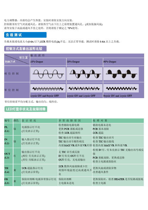
电力调整器,内部均会产生热量,安装时请依安装方向安装。
控制箱须有空气对流通风孔,请依热空气由下往上之原理装置通风孔。
(或加装抽风扇)
请勿安装于高温或通风不佳之处所,否则请低于额定之70%使用。
负载未接或电流太小(0.6A以下)SCR维持电流(lh)不足,无法正常导通,测试时请接0.6A以上之负载。
零位控制采平均分配方式,输出均匀,线性佳。
1.电压、电流讯号源输入且外部VR可调
2.接点讯号输入且外部VR可调
3.手动-自动,RY切换
4.基本输出量设定
5.基本及最高输出量设定
6.多台连接,一只外部VR设定
7.多台连接,各自外部VR设定。
- 1、下载文档前请自行甄别文档内容的完整性,平台不提供额外的编辑、内容补充、找答案等附加服务。
- 2、"仅部分预览"的文档,不可在线预览部分如存在完整性等问题,可反馈申请退款(可完整预览的文档不适用该条件!)。
- 3、如文档侵犯您的权益,请联系客服反馈,我们会尽快为您处理(人工客服工作时间:9:00-18:30)。
SCR3200系列恒功率中频电源控制板中英文说明SCR3200系列中频电源控制板是最新推出的结合787和785电路高度集成化和恒功率控制的优点而生产的最新一代产品,控制板上带整流和逆变脉冲压器。
SCR3200Series intermediate frequency power supply control panelis the newest one.And it unite the excellence of high integration and permanent power control of787&785circuit.The control panel has commutate and inverter pulse.1.控制电路原理The elements of control circuit整个控制电路除末级电路部分外,做成一块印刷电路板结构,从功能上分为整流触发部分、调节器部分、逆变部分、启动演示部分。
详细电路见《SCR3200中频电源控制板电路原理图》。
Whole control circuit(except the last stage circuit part),can make into a piece of PCB construction.It can classify by the function:commutate spring part,adjustor part,inverter part,start-up operate part.Please see the detail circuit as<Elements drawing of SCR3200>.1.1控制板接线说明:The elucidation of connection控制板采用两组15-17V交流电源,分别接于18VAC接线端子上。
A、B、C分别为A相同步,B相同步,C相同步接线,分别直接接于三相工频电上。
The control panel has2groups AC power supply of15-17V.Each of them is connect with the18VAC terminal separate.The meaning of A、B、C:A phase synchronous,B phase synchronous,B phase synchronous connection.27、GND为过流,过压保护的继电器输出端,可设计成声、光及其它方式的报警系统。
当设备主电路发生过压、过流后,整流桥被拉到逆变区的同时,过流、过压继电器动作,点亮面板上的指示灯,在此同时板子上过压、过流工作指示灯变亮。
27、GND is the fan-out of the over current,over voltageprotection relay,can design the alarm system of voice,light and other methods.When the main electric circuit in equipments takes place to over current&over voltage,commutate bridge will bepulled to the inverter area.Over current,over voltage relay will has the action.The indicator light of the control panel will light. And at the same time,the over current&over voltage indicatorlight on the control panel will light.X21、G6,X11、G4,X31、G2为整流桥共阳极组SCR6、SCR4、SCR2三只可控硅触发脉冲的输出端,分别与相应的可控硅的控制极和阴极相接。
X21,G6,X11,G4,X31,G2are the fan-out of the commutate bridge anode groupsSCR6,SCR4,SCR 2.Each of them is connect with the control pole and cathode.G5、1,G3、1,G1、1分别为整流桥共阴极组SCR5、SCR3、SCR1三只可控硅触发脉冲输出端,分别与相应的可控硅的控制极和阴极相接。
G5、1,G3、1,G1、1are the fan-out of the commutate bridge anode groupsSCR5、SCR3、SCR1.Each of them is connect with the control pole and cathode.33、34、35为逆变启动和停止控制输入端,其外接线路如下图2所示:(图中指示灯为发光二极管)33、34、35is the input of the inverter start-up&stop control.See the outside connection as Drawing2.(The indicator light is LED.)(图2)(Drawing2)K1、K2、K3为三相工频交流互感器输入端,通过进线端的500/5A的互感器,再通过5/0.1A的电流互感器二次转换后,星形接于三个接线端子上。
作为过流检测和电流闭环调节的输入信号。
K1,K2,K3are the input of the AC three phase transformer, after the double transform of passing into enter terminal of500/5A transformer&passing5/0.1A current transformer,they will connect with3terminal and like the star shape.As the input signal of over current check¤t close loop adjust.054、055为中频反馈电压输入端,通过1000/15V的中频变压器转变成合适的电压信号输入,作为过压检测和电压闭环调节的输入信号。
054、055are the input of intermediate frequency feed back voltage. After passing1000/15V intermediate frequency transformer,will be transformed to the suitable voltage signal.As the input signal of over voltage check&voltage close loop adjust.073、074、075为功率给定调节电位器输入端,075端接于功率调节电位器的右端点,074接于中间接点,073接于左端点,使功率调节的方向为顺时针功率增大,逆时针功率减小。
073,074and075are the input of the power regulator,075is connect with the right end of the power adjuster,074is connect with the middle one,and the073is connect with the left one.So that the direction of the power regulate will be clockwise power augment,counter-clockwise power minish.G7、7,G8、8,G9、9,G10、10,G11、11,G12、12,G13、13,G14、14为逆变可控硅触发脉冲输出端,分别接于相应可控硅的控制极和阴极上,其中G7、G8、G9、G10为逆变桥的一组对角上的可控硅的控制极输入端,G11、G12、G13、G14为另一组对角的可控硅的控制极输入端。
G7、7,G8、8,G9、9,G10、10,G11、11,G12、12,G13、13,G14、14are the output of the inverter control silicon spring pulse.Each of them is connect with the control pole and cathode.182(-)、183(+)为外接频率表负极与正极的输出接线端。
182(-)、183(+)are output terminal of the frequency table.1.2调整电位器说明:The elucidation of regulator将控制板安装于柜子上,使逆变变压器向下方,按此位置固定的各电位器功能如下:上端三个电位器W7、W8、W9为A、B、C三相同步信号调节电位器,用户一般不需调整。
电位器W6为移相嵌位电压调节电位器,调节此电位器可改变移相电压的起始电位,应使其满足:当功率调节电位器反时针旋到底时,整流主回路应无输出,但触发脉冲应有输出。
最右端的电位器W5为频率表的校正电位器,旋动此电位器,频率表指示可发生变化。
左下方四个电位器从左到右依次为W4限压、W3过压和W2过流、W1限流调整电位器,该电位器为多圈精密电位器,顺时针旋转为整定值减小,逆时针旋转为整定值增大。
The control panel is installed in the cabinet,making the inverter transformer to get down.See the function as follows:The top adjustW7、W8、W9areA、B、C3phase synchronous regulator, don’t need to regulate.W6is the move-phase inbuilt voltage regulator,it can change the start station of move-phase voltage ifregulating W6.But should make its contented:When the power regulates revolve by counter-clockwise,commutate main loop must has no output,but the spring pulse has the loop.The most right machineW5is the proofread one of the frequency table.If we revolve it,the frequency table induction may change.Lower left four machine isW4limited voltage,W3over voltage andW2over current,W1limited current regulator.The setting value will minish if clockwise revolve,and the setting value will augment if counter-clockwise revolve.1.3调节器工作原理Operate elements of regulator调节器部分共设有四个调节器:中频电压调节器、电流调节器、阻抗调节器、逆变角调节器。
